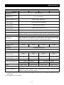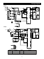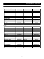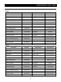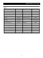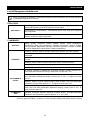
1
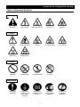
Muffle Furnace Model FP 100/300/310/410 Instruction Manual - Fourth Edition - z Thank you for purchasing " Muffle Furnaces, FP Series" of Yamato Scientific Co., Ltd. z To use this unit properly, read this "Instruction Manual" thoroughly before using this unit. Keep this instruction manual around this unit for referring at anytime. WARNING!: Carefully read and thoroughly understand the important warning items described in this manual before using this unit. Yamato Scientific Co. LTD., This paper has been printed on recycled paper. Contents Cautions in Using with Safety................................................................ 1 • • • Before Using this unit ............................................................................. 4 • Requirements for Installation......................................................................................... 4 Description and Function of Each Part ................................................. 7 • • Explanation.................................................................................................................... 1 Table of Illustrated Symbols .......................................................................................... 2 Fundamental Matters of “WARNING!” and “CAUTION!” ............................................... 3 Main Unit ....................................................................................................................... 7 Control Panel................................................................................................................. 8 Operation Method ................................................................................... 9 • • • • • • • • • • • • • • Preparation.................................................................................................................... 9 Selecting operation mode............................................................................................ 12 Fixed Temperature Operation...................................................................................... 13 Auto Start Operation.................................................................................................... 15 Auto Stop Operation .................................................................................................... 18 Program Operation...................................................................................................... 21 Operating instructions for program menu.................................................................... 24 Create New Program................................................................................................... 26 Edit Program ............................................................................................................... 27 Delete Program ........................................................................................................... 34 Function menu............................................................................................................. 35 Calibration Offset Function.......................................................................................... 45 Independent overheating prevention device ............................................................... 46 Temperature Rise/Fall (Reference Data)..................................................................... 47 Handling Precautions ........................................................................... 48 Maintenance Method............................................................................. 50 • Long storage and disposal................................................................... 51 • Daily Inspection and Maintenance .............................................................................. 50 When not using this unit for long term / When disposing ............................................ 51 In the Event of Failure… ....................................................................... 52 • • • Error Display................................................................................................................ 52 Function of safety devices........................................................................................... 53 Troubleshooting........................................................................................................... 54 After Service and Warranty .................................................................. 55 Specification .......................................................................................... 56 Wiring Diagram...................................................................................... 57 Replacement Parts Table...................................................................... 59 Reference............................................................................................... 62 • List of Dangerous Substances .................................................................................... 62 Cautions in Using with Safety Explanation MEANING OF ILLUSTRATED SYMBOLS Illustrated Symbols Various symbols are used in this safety manual in order to use the unit without danger of injury and damage of the unit. A list of problems caused by ignoring the warnings and improper handling is divided as shown below.Be sure that you understand the warnings and cautions in this manual before operating the unit. warning is ignored, there is the danger of a problem that WARNING! Ifmaythecause a serious accident or even fatality. CAUTION! If the caution is ignored, there is the danger of a problem that may cause injury/damage to property or the unit itself. Meaning of Symbols This symbol indicates items that urge the warning (including the caution). A detailed warning message is shown adjacent to the symbol. This symbol indicates items that are strictly prohibited. A detailed message is shown adjacent to the symbol with specific actions not to perform. This symbol indicates items that should be always performed. A detailed message with instructions is shown adjacent to the symbol. 1 Cautions in Using with Safety Table of Illustrated Symbols Warning Warning, generally Warning, high voltage Warning, high temperature Warning, drive train Warning, explosive Caution, generally Caution, electrical shock Caution, scald Caution, no road heating Caution, not to drench Caution, water only Caution, deadly poison Prohibit, inflammable Prohibit, to disassemble Prohibit, to touch Compulsion, connect to the grounding terminal Compulsion, install on a flat surface Compulsion, disconnect the power plug Caution Prohibit Prohibit, generally Compulsion Compulsion, generally 2 Compulsion, periodical inspection Cautions in Using with Safety Fundamental Matters of “WARNING!” and “CAUTION!” WARNING! Do not use this unit in an area where there is flammable or explosive gas Never use this unit in an area where there is flammable or explosive gas. This unit is not explosion-proof. An arc may be generated when the power switch is turned on or off, and fire/explosion may result. (Refer to page62 “List of Dangerous Substances”.) Always ground this unit Always ground this unit on the power equipment side in order to avoid electrical shock due to a power surge. If a problem occurs If smoke or strange odor should come out of this unit for some reason, turn off the power key right away, and then turn off the circuit breaker and the main power. Immediately contact a service technician for inspection. If this procedure is not followed, fire or electrical shock may result. Never perform repair work yourself, since it is dangerous and not recommended. Do not use the power cord if it is bundled or tangled Do not use the power cord if it is bundled or tangled. fire may be caused. If it is used in this manner, it can overheat and Do not process, bend, wring, or stretch the power cord forcibly Do not process, bend, wring, or stretch the power cord forcibly. Fire or electrical shock may result. Substances that can not be used Never use explosive substances, flammable substances and substances that include explosive or flammable ingredients in this unit. Explosion or fire may occur. Do not disassemble or modify this unit Do not disassemble or modify this unit. Fire or electrical shock or failure may be caused. Do not touch high-temperature parts The inside of the body or the door may become hot during and after an operation. It may cause burns. CAUTION! During a thunder storm During a thunderstorm, turn off the power key immediately, then turn off the circuit breaker and the main power. If this procedure is not followed, fire or electrical shock may be caused. 3 Before Using this unit Requirements for Installation WARNING! 1. Always ground this unit • Connect the power plug to a receptacle with grounding connectors. • Do not forget to ground this unit, to protect you and the unit from electrical shock in case of power surge. Choose a receptacle with grounding connectors as often as possible. • Do not connect the grounding wire to a gas pipe, or by means of a lightning rod or telephone line. A fire or electrical shock will occur. • Though FP300 model is the 100V single phase model, this model has the large electric capacity as 26A. Be sure to prepare the power switchboard with the specific grand earth or specific receptacle. • FP310/410 model is the 200V single phase mode. Be sure to connect this model to the specific power switchboard or receptacle for 200V. 2. Choose a proper place for installation • Do not install this unit in a place where: Rough or dirty surface. Flammable gas or corrosive gas is generated. Ambient temperature exceeds 35°C. Ambient temperature fluctuates violently. There is direct sunlight. There is excessive humidity and dust. There is a constant vibration. • Install this unit on a stable place with the space as shown right. This unit should be installed horizontally by using adjusters on the four corners. More than 30cm More than 30cm (also the reverse side) 52cm ♦ ♦ ♦ ♦ ♦ ♦ ♦ More than 1m Front side 4 Before Using this unit Requirements for Installation 3. Do not use this unit in an area where there is flammable or explosive gas • Never use this unit in an area where there is flammable or explosive gas. This unit is not explosion-proof. An arc may be generated when the power switch is turned ON or OFF, and fire/explosion may result. (Refer to page 62 “List of Dangerous Substances”.) 4. Do not modify • Modification of this unit is strictly prohibited. This could cause a failure. 5. Installation on horizontal surface • Set this unit to the flattest place. Not setting this unit with its legs contacted to the setting place surface evenly could cause the vibration or noise, or cause the unexpectible trouble or malfunction. 5 Before Using this unit Requirements for Installation CAUTION! 6. Choose a correct power distribution board or receptacle • Choose a correct power distribution board or receptacle that meets the unit’s rated electric capacity. Electric capacity: FP100: FP300: FP310: FP410: AC100 V, 13A AC100 V, 26A AC200 V (Single phase), 13A AC200V (Single phase), 17.5A NOTE) There could be the case that the unit does not run even after turning ON the power. Inspect whether the voltage of the main power is lowered than the specified value, or whether other device(s) uses the same power line of this unit. If the phenomena might be found, change the power line of this unit to the other power line. Power cord/terminal treatment Model Specification for power cord (Nominal cross-sectional area of conductor) Terminal treatment on power source FP100 3 cores, 2.0 ㎜ 2 Attachment plug FP300 3 cores, 5.5 ㎜ FP310 3 cores, 3.5 ㎜ 2 FP410 3 cores, 3.5 ㎜ 2 2 Round pressure terminal φ5mm 7. Before/after installing • It may cause injure to a person if this unit falls down or moves by the earthquake and the impact. etc.. To prevent, take measures that the unit cannot fall down, and not install to busy place. • Touching the unit may cause a burn during and after the operation. To prevent, take measures that putting up a notice of operating, making an enclosure etc.. 8. Handling of power code • Do not entangle the power cord. This will cause overheating and possibly a fire. • Do not bend or twist the power cord, or apply excessive tension to it. This may cause a fire and electrical shock. • Do not lay the power cord under a desk or chair, and do not allow it to be pinched in order to prevent it from being damaged and to avoid a fire or electrical shock. • Keep the power cord away from any heating equipment such as a room heater. The cord's insulation may melt and cause a fire or electrical shock. • If the power cord becomes damaged (wiring exposed, breakage, etc.), immediately turn off the power at the rear of this unit and shut off the main supply power. Then contact your nearest dealer for replacement of the power cord. Leaving it may cause a fire or electrical shock. • Connect the power plug to the outlet which is supplied appropriate power and voltage. 6 Description and Function of Each Part Main Unit Mounting area for exhaust device unit Front view Door furnace material Production plate Furnace casing Power cord Independent overheating prevention device l Control panel Earth leakage breaker Power cord (FP100) プ Cooling fan Rear view 7 Description and Function of Each Part Control Panel 6 9 ERROR 10 DOOR ℃ STAND BY END HEATER FIXED TEMP AUTO-START AUTO-STOP PROGRAM 8 11 12 13 FAN 7 14 15 16 5 17 18 MODE PROGRAM MENU POWER 1 2 3 4 ① Mode Key Starts/releases the function menu. ② Program Key Starts/releases the program menu. ③ Menu Key Starts/releases the operation menu. ④ Power Key Turns ON/OFF the power. ⑤ Jog Dial Selects menu item and edit parameters. ⑥ Main Indicator Indicates in-furnace temperature and error number. ⑦ Sub Indicator Indicates various conditions of device with characters. ⑧ ℃ Lamp Lights on while in-furnace temperature is indicated on the main indicator. ⑨ Error Lamp Blinks when any trouble occurs. ⑩ Door Lamp Lights on while the door is open (not provided on this unit). ⑪ Standby Lamp Lights on while the device is in standby condition. in startup wait state. ⑫ End Lamp Blinks at autostop or end of the program operation. ⑬ Heater Lamp Lights on while the heater is active. ⑭ Fan Lamp Lights on while the fan is active. ⑮ Fixed Temp Lamp Lights on during the fixed temperature operation. selecting operation mode. ⑯ Auto Start Lamp Lights on during the auto start operation. operation mode. Blinks when selecting ⑰ Auto Stop Lamp Lights on during the auto stop operation. operation mode. Blinks when selecting ⑱ Program Lamp Lights on during the program operation. operation mode. Blinks when selecting 8 Blinks while it is Blinks when Operation Method Preparation Connect power plug rightly The FP series has two specifications; for 100V and 200V depending on the electric capacity used. Make sure that a proper power terminal/power plug is plugged into an adequate distribution board/socket depending on the electric capacity. Refer to Page 6, “Choose a correct power distribution board or receptacle” for the electric capacity. Set temperature of independent overheating prevention device Set temperature of independent overheating prevention device. Use the projections on the right side of respective digits on the dial digital switch to set the temperature. The device of FP series works in ten times of the set value. For example, it works at the temperature of 1010℃ if the dial is set to “101”, and 1110℃ if set to “111”. 1 0 0 OVERHEAT PREVENTION • In case there is a small difference between the set values of temperature for independent overheating prevention device and that of controller, the independent overheating prevention device may be activated when the temperature reaches to the set value of controller. Set the temperature of independent overheating prevention device so it be at least 100℃ or more higher than that of controller. (When the setting temperature is lower, there is a case that overshoot occurs because this unit is high temperature type furnace. This independent overheating prevention device should be used for protect the unit.) • The default value of the independent overheating prevention device at factory shipment is 1200℃. Set samples rightly Do not load too much samples. Leave a certain space in the furnace. 9 Operation Method Preparation Turn on earth leakage breaker Turn on the earth leakage breaker at the right side of device. ON The main indicator indicates “- - - -“, and after five seconds the sub indicator indicates the current date and time, e.g. “2000-09-17 12:01”,the fun rotates and the fan lamp lights on. ℃ STAND BY END HEATER 2000-09-17 12:01 FAN FIXED TEMP AUTO-START AUTO-STOP PROGRAM NOTE) The clock on device is not set at the factory shipment. Set the date and time referring to the instruction shown on Page 42 “Put clock right”. Press power key FIXED TEMP AUTO START 2000-09-17 12:00 AUTO STOP PROGRAM NU PROGRAM MODE POWER Pressing the power key turns on the power with pip sound. 10 Operation Method Preparation (Continued) ℃ STANDBY END HEATER FIXED TEMP Standing by 2000-09-17 12:01 AUTO START AUTO STOP PROGRAM. FAN The main indicator indicates the in-furnace temperature and the ℃ lamp lights on. The sub indicator displays “standing by” and the standby lamp lights on. called the “standby state”. Pressing the power key again turns off the power. Setting with jog dial Jog dial is used to select the operation mode or to set temperature and clock. Turn jog dial Turning to clockwise: plus Turning to counterclockwise: minus Press jog dial Pressing the jog dial determines the setting and shows the next input window. 11 This state is Operation Method Selecting operation mode The following four operation modes are used. No. Operation mode Function Page 1 Fixed Temperature Operation The device controls the constant temperature. 13 2 Auto Start Operation The device starts operation at the specified time. 15 3 Auto Stop Operation The device stops operation at the specified time. 18 4 Program Operation The device starts programmed operation at the specified time. 21 Operation Selecting Method NOTE) Make sure that the power is on. Press the menu key. MENU The sub indicator indicates operation mode selection window. STANDBY END HEAT FAN FIXED TEMP Fixed temp OP. AUTO START OP.mode choice AUTO STOP PROGRAM The operation mode on the sub indicator blinks and the corresponding lamp blinks. The indication can be changed in the order of “Fixed temperature operation”→”Auto start” →”Auto stop”→”program operation” by turning the jog dial to the right. The corresponding lamp also blinks. Press the menu key again to cancel the selection. The operation mode can be selected from the table below. No. Operation mode Mode Lamp (blink) 1 Fixed Temperature Operation Fixed Temp Lamp 2 Auto Start Operation Auto Start Lamp 3 Auto Stop Operation Auto Stop Lamp 4 Program Operation Program Lamp 12 Sub Indication (The hatching area is blinking.) Fixed temp OP. OP. mode choice Auto-start OP. OP. mode choice Auto-stop OP. OP. mode choice Program OP. OP. mode choice Operation Method Fixed Temperature Operation Select operation mode Press the menu key. Turn the jog dial to indicate “Fixed temp OP.” on the sub indicator and then press the dial. ℃ FIXED TEMP Fixed temp OP. OP. mode choice AUTO START AUTO STOP PROGRAM Set temperature The screen displays the window to set temperature after the fixed temperature operation is determined. The sub indicator indicates “Setup Temp”. The numerical characters that indicate temperature blinks. Indicate the desired temperature. ℃ FIXED TEMP Setup Temp 0℃ Fixed temp OP. AUTO START AUTO STOP PROGRAM Start operation Pressing the jog dial determines the set temperature and starts the operation. ℃ FIXE D TEMP Setup Temp1150℃ Fixed temp OP. AUTO START AUTO STOP PROGRAM The heater lamp lights on and the blinking “Fixed temp” lamp lights on. 13 Operation Method Fixed Temperature Operation Observe temperature during operation The main indicator indicates the in-furnace temperature. STANDBY FIXED TEMP END Setup Temp 1150℃↑ AUTO START HEATER FAN 2000-09-17 13:25 AUTO STOP PROGRAM The current state of temperature control is shown with the indications below at the right end of sub indicator. ↑ : rising ↓ : falling → : stable (within ±2.5) Stop operation Press the power key to stop the operation. POWER 14 Operation Method Auto Start Operation Select operation mode Press the menu key. Turn the jog dial to display “Auto-start OP.” on the sub indicator, then press the dial. ℃ FIXED TEMP Auto-start OP. OP.mode choice AUTO START AUTO STOP PROGRAM Set temperature The screen displays the window to set temperature after the auto start is determined. The sub indicator indicates “Setup Temp”. The numerical characters that indicate temperature blinks. Indicate the desired temperature. ℃ FIXED TEMP Setup Temp 0℃ Auto-start OP. AUTO START AUTO STOP PROGRAM Press the jog dial to determine the set temperature. ℃ FIXED TEMP Setup Temp 1000℃ Auto-start OP. AUTO START AUTO STOP PROGRAM 15 Operation Method Auto Start Operation Set time The screen displays the window to set wait time to operate (period) or start time (the hour) after the set temperature is determined. When timer mode is set to ”Time”: wait time can be input. When timer mode is set to “Clock”: start time can be input. NOTE) The default setting is “Time”. Refer to Page 37 “Select timer mode”. Wait Time Wait time input window Auto-start OP. Start Time Start time input window 13:00 Auto-start OP. For the input of startup wait time, the indication varies as shown below depending on the time range to be indicated. Time Range Indication 0minute to 59minutes 0min to 59min 1hour to 99hours59minutes 1h00m to 99h59m 100hours to 999hours 100hr to 999hr Turn the jog dial to set the desired time. ℃ FIXED TEMP Wait Time 0min Auto-start OP. AUTO START AUTO STOP PROGRAM 30min Press the jog dial to determine the time set above. ℃ FIXED TEMP Wait Time 30min Auto-start OP. AUTO START AUTO STOP PROGRAM 16 Operation Method Auto Start Operation After the wait time or start time is determined, the blinking auto start lamp lights on and the standby lamp blinks instead in startup wait state on auto start mode. The sub indicator shows the set temperature and remaining time. STANDB Y FIXED TEMP END Setup Temp 1000℃ AUTO START HEATER FAN start,rear 10min AUTO STOP PROGRAM Start operation The device starts fixed operation when the remaining time shows “0”. The standby lamp lights off when the operation is started. The sub indicator shows the same indication as in the fixed temperature operation. STANDBY FIXED TEMP END Setup Temp 1000℃↑ AUTO START HEATER FAN 2000-09-17 12:10 AUTO STOP PROGRAM Stop operation Press the power key to stop the operation. POWER 17 Operation Method Auto Stop Operation Select operation mode Press the menu key. Turn the jog dial to indicate the “Auto-stop OP.” on the sub indicator, then press the dial. ℃ FIXED TEMP Auto-stop OP. OP. mode choice AUTO START AYTO STOP PROGRAM Set temperature The screen displays the window to set temperature after the auto stop is determined. The sub indicator indicates “Setup Temp” and the numerical characters that indicate temperature blinks. ℃ FIXED TEMP Setup Temp 0℃ Auto-stop OP. AUTO START AUTO STOP PROGRAM Press the jog dial to determine the set temperature. ℃ FIXED TEMP Setup Temp 1000℃ Auto-stop OP. AUTO START AUTO STOP PROGRAM 18 Operation Method Auto Stop Operation Set time The screen displays the window to set operation time or operation stop hour after the set temperature is determined. When timer mode is set to ”Time”: operation time can be input. When timer mode is set to “Clock”: operation stop hour be input. NOTE) The default setting is “Time”. Refer to Page 37 “Select timer mode”. Stop time Operation time input window Auto-stop OP. Stop time Operation stop hour input window 13:00 Auto-stop OP. For the input of operation time, the indication varies as shown below depending on the time range to be indicated. Time Range Indication 0minute to 59minutes 0min to 59min 1hour to 99hours59minutes 1h00m to 99h59m 100hours to 999hours 100hr to 999hr Turn the jog dial to set the desired time. ℃ FIXED TEMP OP. time 0min Auto-stop OP. AUTO START AUTO STOP PROGRAM 30min Press the jog dial to determine the time set above. ℃ FIXED TEMP OP. time 30min Auto-stop OP. AUTO START AUTO STOP PROGRAM 19 Operation Method Auto Stop Operation Select "Wait Function" The screen changes to the window to select “Wait Function” after the time/hour is set. Turning on the function temporarily stops the countdown of timer if the in-furnace temperature is lower than set temperature by 3℃ or more, or higher by 6℃ or more. The function is available only when the timer mode is set to “Time”. “Clock”, go to the next step. Turn the jog dial to select “ON” or “OFF” and then press it to determine. Wait When it is set to OFF Auto-stop OP. Start operation The auto stop operation starts after the wait function is determined. Blinking auto stop lamp lights on and the sub indicator shows the set temperature and remaining time before operation stop. STANDBY END HEATER FIXED TEMP Setup Temp 1000℃↑ AUTO START Stop,after 30min AUTO STOP PROGRAM FAN If the wait function is set, the sub indicator indicates “Waiting” with blinking if the in-furnace temperature is lower than set temperature by 3℃ or more, or higher by 6℃ or more. Setup Temp 100℃↑ Waiting 30min Stop operation The device stops operation when the remaining time shows “0”. The end lamp blinks when the operation is stopped. The sub indicator shows the operation end time. STANDBY END HEATER FIXED TEMP OP. stop time 2000-09-17 13:00 AUTO STOP PROGRAM FAN Cancel operation AUTO START Press the power key to cancel the operation. 20 Operation Method Program Operation Register the programs with the program menu before starting the program operation. Page 26 “Create New Program” for the registration of programs. Refer to the Select program mode Press the menu key. Turn the jog dial to indicate “Program OP.” on the sub indicator and then press the dial. ℃ FIXED TEMP Program OP. OP. mode choice AUTO START AUTO STOP PROGRAM If no program is set to the device, the buzzer sounds and the sub indicator indicates a message. In this case, register a program with “Create New Program” (refer to the Page 26) and try registration again. A program isn’t Registered Select program mode number Select the program number with the jog dial and then press it to determine. ℃ FIXED TEMP Program P01 Program OP. AUTO START AUTO STOP PROGRAM 21 Operation Method Program Operation Wait time / start time for operation The screen changes to the window to edit wait time (period)/start time (the hour) after the program is determined. When timer mode is set to ”Time”: wait time can be edited. When timer mode is set to “Clock”: start time can be edited. NOTE) The default setting is “Time”. Refer to Page 37 “Select timer mode”. Set the desired time by turning the jog dial. Wait Time Wait time input window 30min Program OP. Start Time Start time input window 13:00 Program OP. Startup wait / startup The device is in the startup wait state of program operation mode after the wait time/ start time is determined. In this situation the blinking program lamp changes to lighting and the standby lamp blinks instead. The sub indicator shows the program number and remaining time to startup. STAND BY END HEATER FIXED TEMP Program P01 Start,rear 30min AUTO START AUTO STOP PROGRAM FAN The device starts operation when the remaining time shows “0”. The standby lamp lights off when the operation is started. The sub indicator shows the segment number currently being executed and the set temperature. STANDBY END HEATER FIXED TEMP Setup Temp 1000℃↑ Segment P01-01 AUTO START AUTO STOP PROGRAM FAN During the ramp operation, the segment number and remaining time are indicated alternately. Setup Temp Segment number currently being executed 100℃↑ Segment P01-01 ↓↑ Setup Temp Remaining time of ramp time Ramp after 22 100℃↑ 30min Operation Method Program Operation Display during soak operation During the soak operation, the segment number and the remaining time of soak time are indicated alternately. In the case the device is in the waiting state, a message “Waiting” is indicated with blinking. Setup Temp Segment number currently being executed 100℃↑ Segment P01-01 ↓↑ Setup Temp Remaining time of soak operation Soak after 30min Setup Temp Waiting state 100℃↑ 100℃↑ Waiting 30min When a segment in repeating section is executed, the segment number and the remaining repeating time are indicated alternately. Setup Temp Remaining repeating time 100℃↑ Rep. rest 10 Complete operation The end lamp blinks when the operation is completed. operation end time. STANDBY END HEATER The sub indicator shows the FIXED TEMP OP.stop time 2000-09-17 15:00 AUTO START AUTO STOP PROGRAM FAN Stop operation Press the power key to release the waiting state or cancel the program operation. POWER 23 Operation Method Operating instructions for program menu The program menu has the three functions listed below. No. Name Function Page 1 Prepare Program Create a new program and resister it. 26 2 Edit Program Edits or checks the registered program. 27 3 Delete Program Deletes the registered program. 34 Select function of program menu Make sure that the power is turned on. Press the program key. PROGRAM The program menu is activated and the screen changes to the function selecting window. STANDBY END HEATER FAN ME FIXED TEMP Prepare Program Entry 0 rest 16 AUTO START AUTO STOP PROGRAM The sub indicator indicates the number of programs already registered and the remaining number of segments. Also the function name currently selected is indicated with blinking. Prepare Program Prepare Program Entry 0 rest 16 rest 16 rest 16 Edit Program Edit Program Entry 0 Delete Program Delete Program Entry 24 0 Operation Method Operating instructions for program menu Turn the jog dial to select the desired program menu. Press the dial to determine menu. The screen changes to the menu input window. Cancel operation Press the program key to cancel the program menu selected. PROGRAM 25 Operation Method Create New Program Select the “Prepare Program” menu Make sure that the remaining number of segment is not ‘0’. If not, delete one of the registered programs before creating a new program. Select the “Prepare Program” on the function selecting window in the program menu and then press the jog dial. ℃ FIXE D TEMP Prepare Program Entry 0 rest 16 AUTO START AUTO STOP゚ PROGRAM Select program number The screen changes to the program number selecting window. The sub indicator indicates “Prepare” and the number in the screen, which shows the program number, blinks. Turn the jog dial to select the desired program number from P01 to P99. NOTE) The program numbers already registered is not indicated here. Prepare Program number selecting window Entry P01 0 rest 16 Press the jog dial to determine the number selected above. The screen changes to the “Edit segment” window after the program number is determined. Go to Page 28 “Edit segment” to edit the segment. 26 Operation Method Edit Program Select “Edit Program” menu Make sure that any program(s) is (are) registered. ℃ FIXED TEMP Edit Program Entry 3 rest 10 AUTO START AUTO STOP PROGRAM Select the “Edit Program” on the function selecting window in the program menu and then press the jog dial. Select program number The screen changes to the program number selection window. The sub indicator indicates “Editing” and the number in the screen, which shows the program number, blinks. Turn the jog dial to select the desired program number to be edited. The segment number the selected program uses and remaining numbers of segment are indicated at the bottom of sub indicator. Editing Program number selecting window Use P01 5 rest 10 Press the jog dial to determine the number selected above. The screen changes to the “Edit segment” window after the program number is determined. Go to Page 28 “Edit segment” to edit the segment. 27 Operation Method Edit Program Edit segment One segment has ten kinds of set item. (*:Optional function) No. Name Setting range 1 Ramp time Step, 1 minute to 999 hours, end 2 Set temperature Within the range of set temperature for the device 3 Soak time 0 minute to 999 hours, hold 4 Wait mode OFF, ON 5 Repeat starting segment None, registered segment number 1 to 16 6 Repeat time 1 to 999, infinite The conception of a segment is shown in the figure below. The “Initial Temperature” means the in-furnace temperature when executing segment No. 1 just after the program operation is started, and also means the set temperature of segment executed last in the case other than mentioned above. Temp Setup temp Start temp Time Ramp time Soak time The conception of a repeat is shown in the figure below. interval is not counted as a repeating time. segment No.1 segment No.2 segment No.3 no repeat instruction no repeat instruction no repeat instruction 5 repeating of interval 28 The first execution of the repeat segment No.4 start repeat segment: 2 repeat time: 5 segment No.5 no repeat instruction Operation Method Edit Program Select set item The screen changes to the item selecting window after the program number is determined in the “Prepare Program” or “Edit Program”. Ramp time Ramp time P01-01 Setup temp Set temperature Soak time Wait mode Repeat start segment Repeat count Segment addition Program end P01-01 Soak time ► 30min rest 10 ► 100℃ rest 10 ► 30min P01-01 rest Wait ► OFF P01-01 rest Rep. start 10 10 ► S01 P01-01 rest 10 Rep.count ► 9999 P01-01 rest 10 rest 10 rest 10 Append seg. P01-01 Program End P01-01 NOTE) The program number and segment number under edition, and remaining number of segment are displayed at the bottom of sub indicator. Turning the jog dial shows the details for all segments registered. The two items, “Segment Addition” and “Program End” are shown after the detail for the last segment number is displayed. 29 Operation Method Edit Program Some set items are not indicated depending on the condition as shown in the list below, which means that the items are invalid in that condition. Item Ramp Time Indication Always indicated. Set Temperature Not indicated when the ramp time is in “End”. Soak Time Not indicated when the ramp time is in “End”. Wait Mode Not indicated when the ramp time is in “End” or soak time is in “Hold”. Repeat Starting Segment Not indicated when the ramp time is in “End” or soak time is in “Hold”. Not indicated when it is between the repeat intervals specified with the other segments. Repeat Time Not indicated when the repeat starting segment is not indicated or in “None”. Segment Addition Not indicated when the ramp time is in “End” or soak time is in “Hold”. NOTE) The content of program under operation is impossible to be changed. The ”►” (cursor) does not appear on the item selecting window. Only checking the program is available during operation. 30 Operation Method Edit Program Edit segment The segment is edited to the program number determined in Page 27 “Select program number”. ℃ FIXED TEMP Ramp time >STEP P01-01 rest 10 AUTO START AUTO STOP PROGRAM Select the set item and press the jog dial. value starts to blink. Item selecting window The blinking ”►” (cursor) disappears and the set Ramp time ► STEP P01-01 rest 10 ↓ Edit window Ramp time STEP P01-01 rest 10 ↓ Turn the jog dial to indicate the desired set item then press it to determine the value and go back to the item selecting. Determine input Ramp time 12h34m P01-01 rest 10 ↓ Edit window Ramp time P01-01 ► 12h34m rest 10 Cancel setting Press the program key to cancel the setting. The input value is cancelled and the screen goes back to the item selecting window. PROGRAM Item selecting window Ramp time P01-01 31 ► STEP rest 10 Operation Method Edit Program Add segment Select the “Append seg” on the item selecting window and then press the jog dial. ℃ FIXED TEMP Append seg. P01-01 rest 10 AUTO START AUTO STOP PROGRAM NOTE) The ”Append seg” is not indicated in the following conditions; the ramp time for the last segment number is in “end”, the soak time is in “hold”, the repeat time is in “limitless”, the key lock mode is in “on”, or the program under edition is being executed. One segment number is added and one remaining number of segment decreases. The screen goes back to the item selecting and the ramp time corresponding to the added segment number is indicated. Segment addition Append Seg. P01-01 rest 10 ↓ Ramp time Edit window P01-02 ► STEP rest The initial settings of newly added segment are listed below. when creating new program are the same as them. 9 The settings of first segment Item Ramp Time Initial value step Note Set Temperature 0℃ Soak Time hold Wait Function OFF Not available because the soak time is in “hold”. Repeat Starting Segment none Not available because the soak time is in “hold”. Repeat Time infinite Not available because the repeat starting segment is not available. 32 Operation Method Edit Program End program edition Select the “Program End” on the items selecting window and then press the jog dial. ℃ FIXED TEMP Program End P01-01 rest 10 AUTO START AUTO STOP PROGRAM NOTE) Pressing the program key on the item selecting window is also possible. 33 Operation Method Delete Program NOTE) ・Make sure that any program(s) is (are) registered. ・Deleting the program under operation is impossible. Select “Delete Program” Select the “Delete Program” on the function selecting window in the program menu and then press the jog dial. ℃ FIXED TEMP Delete Program Entry 3 rest 10 AUTO START AUTO STOP PROGRAM Select program number The screen changes to the program number selecting window. desired program number to be deleted, then press it. program number selecting window Delete Use Turn the jog dial to select the P01 5 rest 10 Check the number and select “Yes” The screen changes to the window to check the program number. Make sure that the correct program number to be deleted is indicated and then press “Yes”. Delete it ? No Delete P01 ↓ Delete it ? Yes Delete P01 NOTE) Press the “No” or program key to cancel the deletion. 34 Operation Method Function menu The function menu has the seven functions listed below. (*:Optional function) No. Name Function 1 Timer Mode Sets the timer mode 37 2 Key Lock Mode Sets the key lock mode. 38 3 Buzzer Mode Sets the buzzer mode. 39 4 Calibration Offset Sets the calibration offset temperature. 40 5 Total Operating Hours Indicates the total operating hours. 41 6 Date/Time Sets the date and time. 42 7 Communication Lock out Sets the communication lock out mode. Mode (*) Select item from function menu Make sure that the power is on. Press the mode key. MODE PROGR The function menu is activated and the item selection window appears. STANDBY END FIXED TEMP Timer mode >time AUTO START AUTO STOP HEATER FAN Page PROGRAM Turning the jog dial indicates the mode. 35 44 Operation Method Function menu Select function Turn the jog dial to select the item indicated on the sub indicator. Timer mode Key lock mode Buzzer mode Timer mode ►time Key lock mode ►OFF Buzzer mode ►ON Calibrate ►±0℃ Calibration offset Total operating hours Date/Time Communication lock out mode Acc. time 49999hr Date ►2000-12-31 Time 23:59 Comm. Lockout Press the jog dial to select the function with the mode indicated. Cancel function setting ►OFF Press the mode key again to cancel the item selection. MODE 36 PROGR Operation Method Function menu Select timer mode Indicate the “Timer mode” on the item selection window in function menu and them press the jog dial. ℃ FIXED TEMP Timer mode >time AUTO START AUTO STOP PROGRAM Select “Time” / “Clock” The “►” (cursor) disappears and the current mode blinks. Turn the jog dial to indicate “time” or “Clock”. Timer mode time ↓ Timer mode Clock Determine mode Press the jog dial. ℃ FIXED TEMP Timer mode>Clock AUTO START AUTO STOP PROGRAM The timer mode is determined and the screen goes back to the item selection window in function menu. 37 Operation Method Function menu Select key lock mode Indicate the “KeyLock mode” on the item selection window in function menu and them press the jog dial. ℃ FIXED TEMP Keylock mode >OFF AUTO START AUTO STOP PROGRAM Select “ON” / “OFF” The “►” (cursor) disappears and the current mode blinks. Turn the jog dial to indicate “ON” or “OFF”. Keylock mode ON ↓ Keylock mode OFF Determine mode Press the jog dial. ℃ FIXED TEMP Keylock mode >ON AUTO START AUTO STOP PROGRAM The keylock mode is determined and the screen goes back to the item selection window in function menu. 38 Operation Method Function menu Select buzzer mode Indicate the “Buzzer mode” on the item selection window in function menu and them press the jog dial. ℃ FIXED TEMP Buzzer mode >ON AUTO START AUTO STOP PROGRAM Select “ON” / “OFF” The “►” (cursor) disappears and the current mode blinks. Turn the jog dial to indicate “ON” or “OFF”. Buzzer mode ON ↓ Buzzer mode OFF Determine mode Press the jog dial. ℃ FIXED TEMP Buzzer mode >OFF AUTO START AUTO STOP PROGRAM The buzzer mode is determined and the screen goes back to the item selection window in function menu. 39 Operation Method Function menu Select calibration offset mode Indicate the “Calibrate” on the item selection window in function menu and them press the jog dial. ℃ FIXED TEMP Calibrate > ± 0℃ AUTO START AUTO STOP PROGRAM Input offset temperature The “►” (cursor) disappears and the current offset temperature blinks. Turn the jog dial to indicate desired temperature. Calibrate ±0℃ ↓ Calibrate +5℃ Determine mode Press the jog dial. ℃ FIXED TEMP Calibrate >+5℃ AUTO START AUTO STOP PROGRAM The calibration offset temperature is determined and the screen goes back to the item selection window in function menu. 40 Operation Method Function menu Select “Acc. Time” NOTE) The “Acc. Time” is a function to check the total operating hour of device. changed. The content cannot be Turn the jog dial on the item selection window to indicate the “Acc. Time”. ℃ FIXED TEMP Acc. time 100hr AUTO START AUTO STOP PROGRAM The total operating hour from the factory shipment to the current time is indicated. Acc. time 100hr NOTE) The total operating hour means the total lapsed time when the power of device is not off. Standby state, startup wait state, and operation end state are included in it. Press the mode key to cancel the function menu when the check is completed. MODE 41 PROGR Operation Method Function menu Put clock right NOTE) The time indicated on the clock is not correct at factory shipment. Before operating this unit, put the clock right. NOTE) The setting of clock cannot be changed at the startup wait state on auto start mode and under operation state on program mode. Press the “Power key” to stop the operation and reset the clock. Turn the jog dial on the item selection window in function menu to indicate the “Date” and “Time”. ℃ FIXED TEMP Date >1999-09-22 Time 17:30 AUTO START AUTO STOP PROGRAM The window indicates the current date and time. Date ►2000-09-22 Time 17:30 Turning the jog dial moves the “►” (cursor) on the window in the order of “Year”, “Month”, “Date”, “Hour” and “Minute”. Date ►2000-09-22 Time 17:30 Date ↓ 2000►09-22 Time 17:30 Date ↓ 2000-09►22 Time 17:30 ↓ Date 2000-09-22 Time ►17:30 ↓ Date 2000-09-22 Time 17►30 42 Operation Method Function menu (continued) Select the desired item and press the jog dial. The “►” (cursor) disappears and the current set value blinks. the value. Date 2000-09-22 Time 17:30 Turn the jog dial to change ↓ Date 2001-09-22 Time 17:30 Press the jog dial. ℃ FIXED TEMP Date 2001-09-22 Time 17:30 AUTO START AUTO STOP PROGRAM The setting is determined and the window goes back to the item selection window in function menu. 43 Operation Method Function menu Select communication lockout mode Indicate the “Comm. Lockout” on the item selection window in function menu and them press the jog dial. ℃ FIXED TEMP Comm. Lockout ON AUTO START AUTO STOP PROGRAM Select “ON” / “OFF” The “►” (cursor) disappears and the current mode blinks. Turn the jog dial to indicate “ON” or “OFF”. Comm. Lockout ON ↓ Comm. Lockout OFF Determine mode Press the jog dial. ℃ FIXED TEMP Comm. Lockout ON AUTO START AUTO STOP PROGRAM The communication lockout mode is determined and the screen goes back to the item selection window in function menu. 44 Operation Method Calibration Offset Function Description In the controller, the relationship between the temperature T detected by the sensor and the display temperature of the operation panel D is expressed by the equation of the line which DS passes the two points (T0, D0) and (TS, DS) shown in Fig.1. Here, T0 is the sensor detecting temperature when the chamber central temperature becomes the zero adjusting temperature y=ax+b D0 (normally room temperature is adopted) D0 at the time of no load, TS is the sensor detecting temperature when the chamber central temperature becomes the span adjustment temperature (normally T0 TS working maximum temperature is adopted) DS at the time of no Sensor detection temperature load in the same way. Fig. 1 As it is clear from the facts above, conforming of the chamber central temperature and the display temperature is guaranteed only when there is no load and at two points shown above. In other words, it is possible for a temperature measured at a point in the chamber does not conform to the display temperature of the operation panel at a voluntary temperature without load. This is the function to move the line which passes above two points to the Y axis direction in parallel (increase or decrease y intercept of the line). The parallel movement amount including a sign is defined as the calibration offset. This function can conform the display temperature of the operation panel to the measurement temperature of a voluntary point in the chamber at a voluntary temperature. Display temperature (Controlled temperature) Display temperature (Controlled temperature) Parallel movement DSV △DCAL DPV Ti TV Sensor detection temperature In Fig.2, DSV is a display temperature of the operation panel under the condition that the temperature in the chamber is constant for a set temperature. It is natural to say that this value is equal to the target set temperature. DPV is a measurement temperature of a voluntary point in the chamber under this condition. The difference between DPV and DSV including the sign is defined as the calibration offset. Therefore offset is shown as below. △DCAL=DPV-DSV Equation 1 Fig.2 In Fig. 2, ΔDCAL becomes the negative value since the target set temperature DSV is larger than the actually measured temperature DPV. In order to conform the display temperature to the actually measured temperature, let the controller to recognize that the temperature in the chamber differs from the target set temperature by ΔDCAL. NOTE) The setting tolerance of calibration offset is ±58℃. The offset value at factory shipment is 0℃. <Example> The fixed temperature operation with a target set temperature of 1000℃ is started. After plenty time has passed from the time the indication on operation panel has reached to 1000℃, the temperature of a certain point in the chamber is measured with a thermometer. The result is 970℃. The indication on the panel is to be equal to the measured temperature (970℃) with the calibration offset function. In this case the calibration offset △Db is expressed with (“measured temperature”― “indicated temperature”)by Equation 1. Therefore, △Db:970℃―1000℃=-30℃ 45 Operation Method Independent overheating prevention device There are two safety devices in this unit: the auto-overheating preventive function of the controller (automatic recovery) and the independent overheating prevention device (manual recovery). Circuits and sensors that are independent from the controller configure them. These safety devices for the temperature overheating prevention protect the instrument in a fail-safe method. Setting the Temperature Range and Function Setting Temperature Range: 10 to 1990℃ Three integer digital switch. Turn the dial of each column and set the desired value. The first integer as the left can only be from 0 to 3 for the hundred columns. Input Method: The device of FP series works in ten times of the set value. For example, it works at the temperature of 1010℃ if the dial is set to “101” ,and 1110℃ if set to “111”. Function: Heater output is cut off when the measured temperature gets higher than the set temperature of the independent overheating prevention device. The function is active when the earth leakage breaker is ON. When the independent overheating prevention device is activated, Er.07 blinks on the main indicator with the ERROR lamp blinks. Activation/Setting Method Usually, set the temperature 100℃ higher than the set temperature of the controller. In the case of the program operation, set it at least 100℃ higher than the maximum set value of the temperature pattern of the program. When the independent overheating prevention device is activated improperly by the next reasons, changing the setting of the device lower than the internal temperature, or by continuing operation when the setting of the device is too low, turn off the earth leakage breaker to reset the main unit and perform the setting again. If it is activated by another reason, refer to the Page 53 “Function of safety devices”. CAUTION! Precautions Only 0 to 3 can be set for the column of hundreds of the digital switch by the stop mechanism; however, if forced to change it to a value higher than 3, it will damage the unit. (Actually, The first integer as the left is a value of thousand.) Set temperature can change by touching the dial when cleaning. Always confirm that the set temperature is correct after cleaning or before operation. 46 Operation Method Temperature Rise/Fall (Reference Data) The following graph shows the data for temperature rise/fall of respective device types. The data shown is only reference because these values vary depending on the quantity of sample or an ambient temperature. Use the data for temperature rise/fall when creating programs. in-furnace temp. (℃) Temperature rising characteristics in FP series 1400 FP100 FP310 1200 FP410 1000 FP300 800 600 400 200 0 0 20 40 60 80 100 120 lapsed time (min.) Temperature falling characteristics in FP series in-furnace temp. (℃) 1000 500 FP300/310/410 FP100 0 0 2 4 6 lapsed time (hour) 47 8 10 Handling Precautions WARNING! If a problem occurs If smoke or strange odor should come out of this unit for some reason, turn off the power key right away, and then turn off the circuit breaker and the main power. Immediately contact a service technician for inspection. If this procedure is not followed, fire or electrical shock may result. Never perform repair work yourself, since it is dangerous and not recommended. Substances that cannot be used Never use explosive substances, flammable substances and substances that include explosive or flammable ingredients in this unit. Explosion or fire may occur. (Refer to page62 ”List of Dangerous Substances”) CAUTION! Do not step on this unit Do not step on this unit. It will cause injury if this unit fall down or break. Do not put anything on this unit Do not put anything on this unit. It will cause injury if fall. Prevention of a burn After an operation, the oven unit and the inside of door, samples have a high temperature for a while. For prevent a burn, be careful that do not touch to the parts in the above when handling samples. During a thunder storm During a thunderstorm, turn off the power key immediately, then turn off the circuit breaker and the main power. If this procedure is not followed, fire or electrical shock may be caused. About the amount of samples If the excessive amount of sample is set, it could be impossible to control the temperature normally. To keep the temperature control accuracy, do not use this unit in overload. Return after power failure When power is supplied after a power failure, the device automatically starts operation again with the same state as just before the power failure. It is danger that the device starts unattached operation after a power failure. We recommend for you to turn off the switch of this unit if a power failure occurs during operation. In-furnace temperature This unit uses a cooling fan to prevent an over temperature of its outer surface during operation when the earth leakage breaker is turned ON. Do not turn OFF the interrupter, or do not disconnect the power supply plug directly when the in-furnace temperature is 600℃ or more after operation, except in the case of emergency. Provide ventilation at the first operation This unit exhausts smoke and smell due to burning of organic matters in the furnace when it is used for the first time. This is not abnormal, but ventilating inside the room should be done. 48 Handling Precautions Furnace may be cracked Though the furnace may be cracked when it is used with high temperature, this does not affect the use or performance of this unit. Open/close door in high temperature affects the device Do not open/close the door as possible at the in-furnace temperature of 500℃ or more, which affects the lives of sensor, oven and heater. Quickly open/close it after operation if necessary. Do not leave door open for a long time at high temperature Leaving the door open for long time at high temperature may cause a radiation heat, which could result in breakdown on the operation panel or controller. Fine powder may fly This unit uses an iron chrome heater. Fine powder from its protective film (oxide film) is possible to be flown during operation. Protect the sample with a cover if needed. Make protective film on heater The heater used on this unit forms a protective film on its surface under high temperature. Make the film by operating this unit for ten hours at the temperature of 1050℃ when using it under the temperature of 700℃ or less. Heater corrosion The heater used on this unit can be corroded with halogen elements such as chlorine, fluorinate or alkali metals such as sodium or potassium. Do not contact these materials to the heater. Sensor deterioration The sensor on this unit (R thermocouple) is very sensitive. Do not contact it to samples when loading or unloading them. Do not touch the sensor with bare hands, which may cause the degradation. Sensor corrosion The sensor used on this unit can be corroded at high temperature with reducing substances such as alkali metal, metal steam, metal oxide, carbon monoxide, carbon, phosphorus, selenium or arsenicum or other reducing ambiences. Do not use these materials. When using N2 gas… Under the Atmosphere of N2 gas, high temperature nitrides the surface of heater, which prevents the formation of protective film on it. Upper limit temperature for use is, therefore, lower than that under atmospheric air. Use the temperature within the range of 100 to 900℃ when operating this unit under N2 gas. Notes for the independent overheating prevention device In case there is a small difference between the set values of temperature for the independent overheating prevention device and that of controller, the overheating prevention device may be activated with displaying Er.07 when the temperature reaches to the set value of controller. Set the temperature of overheating prevention device so it be at least 100℃ or more higher than that of controller. (When the setting temperature is lower, there is a case that overshoot occurs because this unit is high temperature type furnace. This overheating prevention device should be used for protect the unit.)· The default value of the overheating prevention device at factory shipment is 1200℃. Exhaust device unit Connect the ground lead to the exhaust device unit with the main body chassis when it installed. 49 Maintenance Method Daily Inspection and Maintenance WARNING! • • • Disconnect the power cable from the power source when doing an inspection or maintenance unless needed. Perform the daily inspection and maintenance after returning the temperature of this unit to the normal one. Do not disassemble this unit. CAUTION! • • Use a well-drained soft cloth to wipe dirt on this unit. Do not use benzene, thinner or cleanser for wiping. Do not scrub this unit. Deformation, deterioration or color change may result in. Keep the cooling fan clean. Being covered with dust lowers cooling performance. Monthly maintenance • Check the earth leakage breaker function. 1. Connect the power cord. 2. Turn the breaker on. 3. Push the red test switch by a ballpoint pen etc. 4. If there is no problem, the earth leakage breaker will be turned off. • Check the movement of overheating prevention device. Perform the fixed temperature operation of device with certain preset temperature. Then set the operation temperature of overheating prevention device to the value approximately 5℃ lower than the preset temperature of device. In normal condition, the overheating prevention device shuts off the heating circuit in a few seconds, at the same time the alarm lamp lights on and the Er07 is indicated accompanied with a warning buzzer. Be sure to check the movement of earth leakage breaker malfunction and overheating prevention device mentioned above before a long-term continuous operation or unmanned night operation. For any questions, contact the dealer who you purchased this unit from, or the nearest sales division in our company. 50 Long storage and disposal When not using this unit for long term / When disposing CAUTION! When not using this unit for long term… • Turn off the power and disconnect the power cord. WARNING! When disposing… • Keep out of reach of children. • Remove the door and driving parts. • Treat as large trash. Environmental protection should be considered We request you to disassemble this unit as possible and recycle the reusable parts considering to the environmental protection. The feature components of this unit and materials used are listed below. Component Name Main body Body Furnace and Door Plates Electrical Parts Switch, Relays Operation panel Board Heater Power code Wiring Seals Sensor (R thermocouple) Material Steel, Melamine, Epoxy composite resin coating, Stainless steel, SUS304 Ceramic fiber Polyethylene (PET) resin film Resin, Copper, and other composites Alkyl benzene sulfide (ABS) Glass fiber and other composites Iron chrome wire Synthetic rubber coating, Copper, Nickel Glass fiber, Flame resistance plastic, Copper, Nickel Resin material Platinum element 51 In the Event of Failure… Error Display When an error occurs, the buzzer sounds and the ERROR lamp blinks. The main indicator indicates the error number and the sub indicator indicates the detail of error and its corrective actions. Error No. Error Name Er00 Communication error Er.01 Temperature sensor error Er.02 TRIAC short-circuit Er.03 Heater disconnection Er.07 Independent overheating protection device is activated. Er.08 Timer element error Er.10 Main relay error Er.14 RAM error Er.15 EEP ROM error Main indicator Sub indicator Communication Er Ex a connection Sensor Error Calls a service SSR Error Calls a service Heat Error Calls a service Overheat Error Calls a service Controller Er Calls a service Main relay Er Calls a service Controller Er Calls a service Controller Er Calls a service 52 In the Event of Failure… Function of safety devices Safety device Over current earth leakage breaker Function Action Indication Possible cause / corrective action None Check the cause by contacting to our service division. Prevents over current and electric leakage. Power source is cut off. All indications lights off. Prevents overtemperature of device surface Heater circuit is cut off. Warning buzzer Combined with Contact to our service heater cutoff division. detector Independent overheating prevention device Prevents overtemperature Heater circuit is cut off. Warning buzzer ERROR lamp lights on. Er.07 is indicated. Overheating prevention device trouble. Contact to our service division. Sensor abnormality detector Prevents overtemperature due to sensor abnormality Heater circuit is cut off. Warning buzzer ERROR lamp lights on. Er.01 is indicated. Sensor disconnection. Contact to our service division. Gives a warning against temperature uncontrollability Heater circuit is cut off. Warning buzzer ERROR lamp lights on. Er.03 is indicated. Heater or thermal fuse disconnection. Contact to our service division. Prevents overtemperature due to heater uncontrollability Heater circuit is cut off. Warning buzzer ERROR lamp lights on. Er.02 is indicated. Triac short circuit. Contact to our service division. Gives a warning against incapability Heater circuit is cut off. Warning buzzer ERROR lamp lights on. Er.10 is indicated. Main relay trouble. Contact to our service division. Checks electronic circuit Heater circuit is cut off. Warning buzzer ERROR lamp lights on. Er.08 or Er.14 is indicated. Contact to our service division. Prevents overtemperature Heater circuit is cut off. (in-furnace temperature: rising) None High fever of sample. Contact to our service division. None Activate during operation to prevent discontinuance due to wrong operation. Refer to the Page 38 to set/release the function. Thermal fuse Heater disconnection detector Triac short circuit detector Main relay defect detector POST function (*) Automatic overheating prevention Key lock Prevents wrong operation Memory backup circuit Stores memory in case of power failure Input impossible in key lock state except the mode key None *: The POST (Power On Self Test) function checks the microprocessor, memory, peripheral LSI and peripheral circuit on the controller every time the power is turned on. It checks the existence of fatal error on the controller before operation. 53 In the Event of Failure… Troubleshooting Problem The sub indicator does not indicate current date and time when the electric leakage breaker is turned on. Possible Cause Power is not supplied. Bad condition of the earth leakage breaker Bad condition of the controller The cooling fan does not move when the electric leakage Bad condition of the cooling fan breaker is turned on. The operation panel indicates none when the power key is pressed. Temperature does not rise. Problem in power source Bad condition of the controller Heater circuit is interrupted by self-diagnosis function (Error code is indicated) Heater deterioration Variable ambient temperature Instable indication of temperature Noisy Too much samples loaded Bad condition of the controller Bad condition of the sensor Cooling fan deterioration Solution Check the connection and turn on electricity. Replace the part (*) Replace the part (*) Connect to the appropriate power source. Replace the part (*) Refer to the Page 53 “Function of safety devices”. Replace the part (*) Change the installation location. Reduce the quantity of sample. Replace the part (*) Replace the part (*) *: Please contact to the shop of your purchase or nearest branch office of Yamato Science for the troubleshooting of items with the “*” mark. When an error occurs... • • In case these error code mentioned above is displayed, recode the error code and shut off the power immediately. In case “ Er14” is displayed, once turn off a circuit breaker. Then, after more than 30seconds, turn on the breaker again. In case “Er14”is still displayed even after the breaker is turned on, then contact us. When power failure occurs… • • When power is supplied after a power failure, the device automatically starts operation again with the same state as just before the power failure. It is danger that the device starts unattached operation after a power failure. We recommend for you to turn off the switch of device if a power failure occurs during operation. In the case if the error other than listed above occurred, turn off the power switch and primary power source immediately. Contact the shop of your purchase or nearest Yamato Scientific Service Office. 54 After Service and Warranty In Case of Request for Repair If the failure occurs, stop the operation, turn OFF the power switch, and unplug the power plug. Please contact the sales agency that this unit was purchased, or the Yamato Scientific's sales office. < Check following items before contact > ◆ ◆ ◆ ◆ Model Name of Product See the production plate attached to this unit. Production Number Purchase Date About Trouble (in detail as possible) Minimum Retention Period of Performance Parts for Repair The minimum retention period of performance parts for repair of this unit is 7 years after discontinuance of this unit. The "performance part for repair" is the part that is required to maintain this unit. 55 Specification FP100 FP300 Operating temperature range (*1) FP310 100 to 1150℃ Temperature adjustment accuracy (*1) ±1.5℃ (@1150℃) Time required to reach highest temperature (*1) Approx. 80min. (@1150℃) Temperature control system PID control by micro computer Temperature / time setting system Digital setting by jog dial Temperature display system Digital display by green LED Other indications Fluorescent character display of function Functions for Operation FP410 Fixed temperature operation, Auto start operation, Auto stop operation, Program operation (max. of 16 segments, repeat operation, Ramp operation, etc.) Additional function Timer, Clock, Total operating hours counter (max. of 49999h), Calibration offset Safety device Earth leakage breaker, Thermal fuse, Independent overheating prevention device, Key lock function, Self-diagnostic functions (Sensor error, Memory error, Heater disconnection, Triac short circuit, Automatic overheating prevention) Sensor R thermocouple (W sensor) Heater Pyromax Nominal capacity of heater 1.1KW 2.4KW 2.4KW Cooling fan Condenser motor 14W Exhaust opening Internal diameter φ18 Furnace casing 3.25KW Single piece vacuum ceramic fiber Internal dimensions (W×D×H mm) Approx. 100×150×100 Approx. 200×250×150 Approx. 200×250×150 Approx. 300×250×150 External dimensions (*2) (W×D×H mm) Approx. 346×405×516 Approx. 446×505×566 Approx. 446×505×566 Approx. 506×505×626 Approx. 1.5L Approx. 7.5L Approx. 7.5L Approx. 11.3L Internal capacity Power supply(50/60Hz) Weight 100V AC single phase 200V AC single phase 13A 26A 13A 17.5A Approx. 24Kg Approx. 42Kg Approx. 42Kg Approx. 48Kg Attached accessories Instruction manual, Warranty, Thermal fuse Optional accessories Exhaust device unit, Sample tray, N2 gas leading device, External alarm, Temperature output terminal, Outer communication adapter, Time-up output terminal, Cooling fan automatic stopper *1: The value under the condition of the ambient temperature of 23℃±5℃, the humidity of 65%±20%, and without load. *2: The projection is not included. 56 Wiring Diagram FP100 FP300 Control panel ELB AC100V P2 P1 1 1 1 2 3 4 5 Tr X2 2 3 CR 4 SSR1 T1 T2 SSR2 J1 2 OH 3 1 2 X1 1 3 4 1 2 3 4 1 J2 6 1 2 1 5 6 J7 X1 X2 30 1 1 2 1 1 Fluorescent Display J1 PIO7 J2 12 11 12 J8 7 8 4 30 J22 1 2 3 4 5 6 J3 J4 J21 2 12 Jog dial J5 1 2 3 1 J19 3 Overheating prevention temp. setting digital switch Main relay TH FM 1 J1 2 3 T1 T2 1 20 CN J4 2 2 H F 3 4 5 1 J1 1 J3 2 3 4 1 2 3 4 J10 12 Heater structure 1 2 3 4 H3 1 2 J15 3 J5 4 H1 H2 Symbol Part name PLANAR Symbol Part name ELB Earth leakage breaker P1 FM Fan motor X1 Relay CN Connector Tr Transformer Fuse OH Independent overheating prevention device F 57 Terminal block FI Wiring Diagram FP310 FP410 Control panel ELB AC200V P2 P1 1 1 Tr X2 2 T1 T2 3 CR T1 T2 4 SSR1 J1 SSR2 1 20 OH 3 CN 1 2 J1 1 2 3 4 J2 X1 1 2 3 1 J1 2 3 Overheating prevention temp. setting digital switch X1 Main relay TH FM X2 1 1 5 6 J7 30 30 1 1 2 1 1 Fluorescent Display J1 PIO7 J2 J22 12 11 1 2 3 4 5 6 J3 J4 J21 2 12 1 2 3 1 J19 12 J8 7 8 4 1 2 3 4 J10 1 J3 2 3 4 12 Heater structure Symbol 3 4 J5 Jog dial 5 6 1 2 1 J4 2 3 4 2 H F 1 2 3 4 5 H1 H3 H2 H4 Part name 1 2 3 4 1 2 J5 J15 3 4 PLANAR Symbol Part name ELB Earth leakage breaker P1 FM Fan motor X1 Relay CN Connector Tr Transformer Fuse OH Independent overheating prevention device F 58 Terminal block FI Replacement Parts Table Common Use Parts Part Name Code No. Specification Manufacturer Control board (HITEC IV CRII) 1240000120 Yamato Scientific Display circuit board (PIO7) 1240000084 Yamato Scientific Tough card 1130000007 0-8370-307-000-800 CT sensor 2170010002 CTL-6-S-4-H Relay(X1) 2050000013 AHN36006 Matsushita Thermal fuse LT00031819 25A 250V E8A50184C EMERSON Independent overheating prevention device 1240000100 IV-LE type Fuji Denki Degi-switch 2010100002 For IV-LE Fuji Denki W sensor 1016007002 R-thermocouple Fan guard 4370010003 A-30-F Fiber for heater (6 pieces) FP21S41451 Japan Autonics Yamato Scientific Yamato Scientific Minebea Yamato Scientific FP100 Part Name Code No. Specification Manufacturer SSR LT00028423 SSR-01 Yamato Scientific Power code LT00008924 T2-3c Yamato Scientific Earth leakage breaker LT00029774 NV-L22GR 15A Transformer 2180000040 IVCR2 100V Yamato Scientific Fan motor 2150000010 UF12A10BTH FULLTECH Heater (A) LT00032208 Hachikou Syoji Heater (B) (2 pieces) LT00032209 Hachikou Syoji Door furnace material FP10030120 FP100 type Nichiasu Furnace material FP21S22010 FP100 type Nichiasu Furnace port material FP21S40311 FP100 type Nichiasu Furnace front plate FP21S32040 FP100 type Kurata Taika Fiber for ceiling FP22S40220 Yamato Scientific Fiber for the side (2 pieces) FP21S40261 Yamato Scientific Fiber for the bottom LT00017249 Yamato Scientific Fiber for the rear LT00008757 Yamato Scientific Terminal block LT00031663 TFD250ABC-6P 59 Mitsubishi Terminal Replacement Parts Table FP300 Part Name Code No. Specification Manufacturer SSR1 LT00028427 SSR-01A Yamato Scientific SSR2 LT00028425 SSR-01B Yamato Scientific Power code 2130010010 T3-3e Yamato Scientific Earth leakage breaker LT00029777 NV-L22GR 30A Mitsubishi Relay(X2) LT00005140 AHE1274 Matsushita Transformer 2180000040 IVCR2 100V Yamato Scientific Fan motor 2150000010 UF12A10BTH FULLTECH Heater (A) LT00032206 Hachikou Syoji Heater (B) (2 pieces) LT00032207 Hachikou Syoji Door furnace material FP30030100 FP300 type Nichiasu Furnace material FP31S20080 FP300 type Nichiasu Furnace port material FP31S40171 FP300 type Nichiasu Furnace front plate FP31S30170 FP300 type Kurata Taika Fiber for ceiling FP32S40110 Yamato Scientific Fiber for the side (2 pieces) FP32S40120 Yamato Scientific Fiber for the bottom LT00017253 Yamato Scientific Fiber for the rear LT00008758 Yamato Scientific Terminal block LT00031661 TFD250ABC-4P Terminal FP310 Part Name Code No. Specification Manufacturer SSR LT00028423 SSR-01 Yamato Scientific Power code 2130010010 T3-3d Yamato Scientific Earth leakage breaker Lt00039774 NV-L22GR 15A Transformer 2180000042 IVCR2 200V Fan motor 2150040007 4715PS-20T-b30-100 Heater (A) LT00032206 Hachikou Syoji Heater (B) (2 pieces) LT00032207 Hachikou Syoji Door furnace material FP30030100 FP300 type Nichiasu Furnace material FP31S20080 FP300 type Nichiasu Furnace port material FP31S40171 FP300 type Nichiasu Furnace front plate FP31S30170 FP300 type Kurata Taika Fiber for ceiling FP32S40110 Yamato Scientific Fiber for the side (2 pieces) FP32S40120 Yamato Scientific Fiber for the bottom LT00017257 Yamato Scientific Fiber for the rear LT00008759 Yamato Scientific Terminal block LT00031663 TFD250ABC-6P 60 Mitsubishi Yamato Scientific Minebea Terminal Replacement Parts Table FP410 Part Name Code No. Specification Manufacturer SSR1 LT00028427 SSR-01A Yamato Scientific SSR2 LT00028425 SSR-01B Yamato Scientific Power code 2130010010 T3-3d Yamato Scientific Earth leakage breaker LT00029777 NV-L22GR 30A Mitsubishi Relay(X2) LT00005140 AHE1274 Matsushita Transformer 2180000042 IVCR2 200V Fan motor 2150040007 4715PS-20T-b30-100 Heater (C) LT00032203 Hachikou Syoji Heater (D) LT00032204 Hachikou Syoji Heater (E) (2 pieces) LT00032205 Hachikou Syoji Door furnace material FP41030110 FP400 type Nichiasu Furnace material FP41S20090 FP400 type Nichiasu Furnace port material FP41S30171 FP400 type Nichiasu Furnace front plate FP41S30160 FP400 type Kurata Taika Fiber for ceiling FP42S40150 Yamato Scientific Fiber for the side (2 pieces) FP32S40120 Yamato Scientific Fiber for the bottom LT00017257 Yamato Scientific Fiber for the rear LT00008759 Yamato Scientific Terminal block LT00031661 TFD250ABC-4P 61 Yamato Scientific Minebea Terminal Reference List of Dangerous Substances Never use explosive substances, flammable substances and substances that include explosive or flammable ingredients in this unit. EXPLOSIVE Ethylene glycol dinitrate (nitro glycol), Glycerin trinitrate (nitroglycerine), Cellulose nitrate (nitrocellulose), and other explosive nitrate esters EXPLOSIVE: Trinitrobenzene, Trinitrotoluene, Trinitrophenol (picric acid), and other explosive nitro compounds Acetyl hidroperoxide (peracetic acid), Methyl ethyl ketone peroxide, Benzyl peroxide, and other organic peroxides FLAMMABLE IGNITING: Lithium (metal), Potassium (metal), Sodium (metal), Yellow phosphorus, Phosphorus sulfide, Red phosphorus, Celluloid compounds, Calcium carbide, Lime phosphate, Magnesium (powder), Aluminum (powder), Powder of metals other than magnesium and aluminum, Sodium hydrosulfite Potassium chlorate, Sodium chlorate, Ammonium chlorate, and other chlorate Potassium perchlorate, Sodium perchlorate, Ammonium perchlorate, and other perchlorate OXIDIZING: Potassium peroxide, Sodium peroxide, Barium peroxide, and other inorganic peroxide Potassium nitrate, Sodium nitrate, Ammonium nitrate, and other nitrate Sodium chlorite and other chlorites Calcium hypochlorite and other hypochlorites Ethyl ether, Gasoline, Acetaldehyde, Propylene chloride, Carbon disulfide, and other flammable substances having a flash point of lower than -30℃ INFLAMMABLE LIQUID: Normal hexane, ethylene oxide, acetone, benzene, methyl ethyl ketone, and other flammable substances having a flash point of -30℃ or higher but lower than 0℃ Methanol, Ethanol, Xylene, Pentyl acetate (amyl acetate), and other flammable substances having a flash point of 0℃ or higher but lower than 30℃ Kerosene, Light oil (gas oil), Oil of turpentine, Isopentyl alcohol (isoamyl alcohol), Acetic acid, and other flammable substances having a flash point of 30℃ or higher but lower than 65℃ FLAMMABLE GAS: Hydrogen, Acetylene, Ethylene, Methane, Propane, Butane, and other flammable substances which assume a gaseous state at 15℃ and 1 atm (Source: Appendix Table 1 of Article 6 of the Industrial Safety and Health Order in Japan) 62 Responsibility Please follow the instructions in this document when using this unit. Yamato Scientific has no responsibility for the accidents or breakdown of device if it is used with a failure to comply. Never conduct what this document forbids. Unexpected accidents or breakdown may result in. Note ◆ The contents of this document may be changed in future without notice. ◆ Any books with missing pages or disorderly binding may be replaced. Instruction Manual for Muffle Furnace Model FP100/300/310/410 Fourth Edition Oct. 7, 2009 Revised Feb. 24, 2012 Yamato Scientific Co., Ltd. 2-1-6 Nihonnbashi Honcho, Chuo-ku, Tokyo, 103-8432, Japan Customer Support Center (toll-free) 0120-405525 http://www.yamato-net.co.jp 63