1
OPERATING AND
SERVICE MANUAL
Relay Accessories
Agilent Models 59510A, 59511A
Agilent Part No. 5957-6382
Serial Numbers:
Agilent Model 59510A, Serials US29080101 and Above
Agilent Model 59511A, Serials US29060101 and Above
* This manual also applies to instruments with the older serial number format described on page 7.
Microfiche Part No. 5957-6383
Printed in USA: April, 1988
SAFETY SUMMARY
The following general safety precautions must be observed during all phases of operation, service, and repair of this
instrument. Failure to comply with these precautions or with specific warnings elsewhere in this manual violates safety
standards of design, manufacture, and intended use of the instrument. Agilent Technologies Company assumes no liability
for the customer’s failure to comply with these requirements.
BEFORE APPLYING POWER.
Verify that the product is set to match the available line voltage and the correct fuse is installed.
GROUND THE INSTRUMENT.
This product is a Safety Class 1 instrument (provided with a protective earth terminal). To minimize shock hazard, the instrument chassis
and cabinet must be connected to an electrical ground. The instrument must be connected to the ac power supply mains through a threeconductor power cable, with the third wire firmly connected to an electrical ground (safety ground) at the power outlet. For instruments
designed to be hard-wired to the ac power lines (supply mains), connect the protective earth terminal to a protective conductor before any
other connection is made. Any interruption of the protective (grounding) conductor or disconnection of the protective earth terminal will
cause a potential shock hazard that could result in personal injury. If the instrument is to be energized via an external autotransformer for
voltage reduction, be certain that the autotransformer common terminal is connected to the neutral (earthed pole) of the ac power lines
(supply mains).
FUSES.
Only fuses with the required rated current, voltage, and specified type (normal blow, time delay, etc.) should be used. Do not use repaired
fuses or short circuited fuseholders. To do so could cause a shock or fire hazard.
DO NOT OPERATE IN AN EXPLOSIVE ATMOSPHERE.
Do not operate the instrument in the presence of flammable gases or fumes.
KEEP AWAY FROM LIVE CIRCUITS.
Operating personnel must not remove instrument covers. Component replacement and internal adjustments must be made by qualified
service personnel. Do not replace components with power cable connected. Under certain conditions, dangerous voltages may exist even
with the power cable removed. To avoid injuries, always disconnect power, discharge circuits and remove external voltage sources before
touching components.
DO NOT SERVICE OR ADJUST ALONE.
Do not attempt internal service or adjustment unless another person, capable of rendering first aid and resuscitation, is present.
DO NOT EXCEED INPUT RATINGS.
This instrument may be equipped with a line filter to reduce electromagnetic interference and must be connected to a properly grounded
receptacle to minimize electric shock hazard. Operation at line voltages or frequencies in excess of those stated on the data plate may
cause leakage currents in excess of 5.0 mA peak.
SAFETY SYMBOLS.
Instruction manual symbol: the product will be marked with this symbol when it is necessary for the user to refer to the
instruction manual (refer to Table of Contents) .
Indicates hazardous voltages.
Indicate earth (ground) terminal.
The WARNING sign denotes a hazard. It calls attention to a procedure, practice, or the like, which, if not correctly
performed or adhered to, could result in personal injury. Do not proceed beyond a WARNING sign until the
indicated conditions are fully understood and met.
The CAUTION sign denotes a hazard. It calls attention to an operating procedure, or the like, which, if not correctly
performed or adhered to, could result in damage to or destruction of part or all of the product. Do not proceed
beyond a CAUTION sign until the indicated conditions are fully understood and met.
DO NOT SUBSTITUTE PARTS OR MODIFY INSTRUMENT.
Because of the danger of introducing additional hazards, do not install substitute parts or perform any unauthorized modification to the
instrument. Return the instrument to an Agilent Technologies Sales and Service Office for service and repair to ensure that safety features
are maintained.
Instruments which appear damaged or defective should be made inoperative and secured against unintended operation until they can be
repaired by qualified service personnel.
2
Table of Contents
General Information............................................................................................................................................................... 5
Introduction .......................................................................................................................................................................... 5
Description (Figure 1-1) ....................................................................................................................................................... 5
Specifications........................................................................................................................................................................ 7
Safety Considerations ........................................................................................................................................................... 7
Instrument and Manual Identification................................................................................................................................... 7
Options ................................................................................................................................................................................. 7
Installation............................................................................................................................................................................. 10
Introduction ........................................................................................................................................................................ 10
Initial Inspection ................................................................................................................................................................. 10
Mounting ............................................................................................................................................................................ 10
Surface Mounting ........................................................................................................................................................... 10
Option 850 Mounting ..................................................................................................................................................... 11
Input Power Requirements.................................................................................................................................................. 12
Power Cord ......................................................................................................................................................................... 13
Connections and Operating Information............................................................................................................................ 15
Introduction ........................................................................................................................................................................ 15
Agilent 595lXA Front Panel ............................................................................................................................................... 15
DC Power Connections....................................................................................................................................................... 17
Sense Lead Connections ..................................................................................................................................................... 18
Remote Sensing .............................................................................................................................................................. 18
Local Sensing (Figure 3-3) ............................................................................................................................................. 19
Agilent 603XA Configuration ............................................................................................................................................ 19
Switch Settings ............................................................................................................................................................... 20
CONFIG Switches ...................................................................................................................................................... 20
RLY LINK or INH/ FLT Switch ................................................................................................................................ 22
Agilent 603XA/5951XA Serial Data Connection........................................................................................................... 22
Agilent 603XA/5951XA Configuration Wake-Up State ................................................................................................ 22
Remote Inhibit (INH) and Fault (FLT) Lines ................................................................................................................. 23
INH Input Line ........................................................................................................................................................... 24
FLT Output Line......................................................................................................................................................... 24
Using INH and FLT with Multiple Agilent 603XA/5951XA’s................................................................................... 24
Agilent 603XA Status PoII ............................................................................................................................................. 24
Agilent 603XA/5951XA Turn-On Sequence.................................................................................................................. 25
General Purpose Configuration........................................................................................................................................... 26
Switch Settings ............................................................................................................................................................... 27
Agilent 603X LINK or LOGIC CONTROL Switch ................................................................................................... 27
Listen Enable Switch .................................................................................................................................................. 27
TTL Input Connections................................................................................................................................................... 27
LISTEN ENABLE Input. ........................................................................................................................................... 28
OPEN/CLOSE Signal ................................................................................................................................................. 28
NORM/REVInput (Applies only to Agilent Model 59511A). .................................................................................... 28
Remote Inhibit (INH) and Fault (FLT) Lines ................................................................................................................. 28
3
Agilent 603XA Programming Commands .......................................................................................................................... 31
Introduction ........................................................................................................................................................................ 31
Changed Command............................................................................................................................................................. 32
Output On/Off................................................................................................................................................................. 32
Added Commands............................................................................................................................................................... 34
DC On/Off ...................................................................................................................... ................................................ 34
Relay On/Off .................................................................................................................................................................. 35
Polarity Normal/Reverse (Model 59511A only)............................................................................................................. 35
Maintenance .......................................................................................................................................................................... 37
Introduction ........................................................................................................................................................................ 37
Circuit Operation ................................................................................................................................................................ 37
Main Circuit Board ......................................................................................................................................................... 37
Control Circuits .......................................................................................................................................................... 37
Bias Supply................................................................................................................................................................. 38
Power-on Circuit......................................................................................................................................................... 38
Relays ......................................................................................................................... .................................................... 39
Verification......................................................................................................................................................................... 40
Relay Control Verification (TTL Mode) ........................................................................................................................ 40
DC Power Relay Verification ......................................................................................................................................... 41
Removal and Replacement Procedures............................................................................................................................... 42
Cover .......................................................................................................................... .................................................... 42
Assembly Removal......................................................................................................................................................... 43
Main Circuit Board Removal.......................................................................................................................................... 43
Troubleshooting Procedures ............................................................................................................................................... 43
Test Setup ..................................................................................................................... .................................................. 43
Bias Supply and Power-On Circuit................................................................................................................................. 44
Microprocessor U101 ..................................................................................................................................................... 44
Relay Circuits ................................................................................................................................................................. 45
Agilent Model 59510A. .............................................................................................................................................. 45
Agilent Model 59511A. .............................................................................................................................................. 45
FLT and INH Circuits..................................................................................................................................................... 46
Parts List..................................................................................................................... ........................................................ 47
Agilent Sales and Support offices ........................................................................................................................................56
4
1
General Information
Introduction
This manual contains instructions for installing, operating and troubleshooting the Agilent Model 59510A and 59511A
Relay Accessories. Each of these models is designed for use with the Agilent 6030A, 6032A, 6033A, and 6038A models in
the Agilent 603XA series of system power supplies. The Agilent 59510A and Agilent 59511A Relay Accessories can be
used with Agilent 603XA supplies that have the following serial numbers:
Agilent Model
6030A
6031A**
6032A
6033A
6038A
Serial Numbers *
2811A-00815 and above
2817A-00983 and above
2818A-03121 and above
2817A-03452 and above
2817A-05426 and above
* Models with lower serial numbers can be modified to operate with the Agilent 595XA Relay Accessory. Consult Agilent
regarding a retrofit kit for these models.
**When the Agilent 5951XA Relay Accessory is to be used with the Agilent 6031A System DC Power Supply, care must be
taken to set the Agilent 6031A’s current limit to 60 A or less. The Agilent 6031A power supply is capable of delivering
an output current in excess of Agilent 5951XA’s rating of 60 A, which could cause damage to the Relay Accessory.
Wherever applicable, the instructions given in this manual refer to pertinent information provided in the Operating and
Service Manual for the appropriate Agilent 603XA power supply as follows:
Agilent Model
6030A
6031A
6032A
6033A
6038A
Manual Agilent P/N
06030-90003
06031-90003
06032-90005
06033-90010
06038-90003
The Relay Link Supplement, Appendix F (Agilent Part No. 5957-6388) to the above manuals, describes circuit changes to
the Agilent 603X supplies which allow use of the supplies with the Agilent 59510A/59511A. The Agilent 59510A/59511A
Relay Accessory has a logic control input (TTL levels) that allows it to be used with power supplies or devices other than
the supplies specified above. Instructions for using the logic control input in a general purpose configuration are given in
Section 3 of this manual.
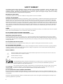
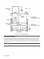
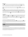
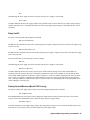
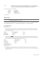
Description (Figure 1-1)
The Agilent 59510A and 59511A Relay Accessories are intended for use in power supply applications where either or both
load isolation (connect/disconnect) and polarity reversal are required.
The Agilent 59510A Relay Accessory provides for load connect/disconnect for both the power output and sense leads of the
power supply. The Agilent 59511A Relay Accessory provides for polarity reversal as well as for load connect/disconnect
for both power output and sense leads. In addition, each model includes a fault (FLT) output line and a remote inhibit (INH)
input line. The FLT output line provides a fault reporting capability that is independent of the GPIB service request (SRQ)
General Information
5
function. The INH input line provides a way to remotely disconnect (also independent of GPIB computer control) the power
supply output.
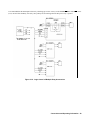
Figure 1-lA shows the Agilent 59510A/59511A Relay Accessory configured with an Agilent 603XA power supply. A GPIB
interface in the Agilent 603XA power supply recognizes relay commands from the computer and provides serial data to the
Agilent 59510A/59511A via a special connection labeled RLY LINK. The Agilent 5951XA converts the serial data into
relay control signals.
The computer can control the connect/disconnect and polarity reversal (Agilent 59511A only) functions via the Agilent
603XA supply’s serial data link to the Agilent 59510A/59511A. The closing and opening of the relays in the Agilent
59510A/59511A can be coordinated with the enabling and disabling of the power supply output to allow switching the
relays when the power supply output is disabled in order to prolong relay life. The microprocessor within the Agilent
59510A/59511A Relay Accessory properly sequences the power and sense relays to minimize overshoots at the power
supply output.
Figure 1-lB shows the Agilent 59510A/59511A Relay Accessory configured in a general purpose application. This
configuration allows the Agilent 59510A/59511A to be used with power supplies or devices other than Agilent 603XA
power supplies. Logic control inputs are provided that allow TTL logic levels to control the connect/disconnect and polarity
reversal (Agilent 59511A) functions. The logic control inputs have pull-up resistors which allow them to accept signals from
relays or open-collector devices.
The Agilent 59510A/59511A Relay Accessory is designed to fit in a rack height of 5¼ inches and is approximately 7¼
inches wide and 8 inches deep. All necessary connections are made at the front panel.
Figure 1-1. Agilent 59510A/59511A Configurations
6
General Information
Specifications
Table 1-1 lists the specifications for the Agilent 59510A/59511A Relay Accessories. The 603XA power supply
specifications are listed in the applicable manual (see page 1).
Safety Considerations
This product is a Safety Class 1 instrument, which means that it is provided with a protective earth terminal. The instrument
and this manual should be reviewed for safety markings and instructions before operation. Refer to the Safety Summary
page at the beginning of this manual for a summary of general safety information. Safety information for specific procedures
is located at appropriate places in the manual.
The Agilent 5951XA Relay Accessory contains mercury displacement relays. Because mercury is a hazardous material,
defective relays must be disposed of properly (refer to page 38).
Agilent Technologies power supplies are designed to comply will the following regulatory standards: IEC 348, VDE 0411,
CSA 556B, VDE 0871/6.78 level B (FTZ 1046/84), UL1244.
Instrument and Manual Identification
Agilent Technologies instruments are identified by a 10-digit serial number. The first two letters indicate the country of
manufacture. The next four digits are a code that identify either the date of manufacture or of a significant design change.
The last four digits are a sequential number assigned to each instrument.
Older serial number formats used with these instruments had a two-part serial number, i.e. 2701A-00101. This manual also
applies to instruments with these older serial number formats.
If the serial number prefix on your Relay Accessory differs from that shown on the title page of this manual, a yellow
Manual Change sheet that is supplied with the manual defines the differences between your unit and the unit described in
this manual. The yellow change sheet may also contain information for correcting errors in the manual.
Options
850: One rack mount kit.
910: One extra operating and service manual shipped with each Relay Accessory.
W30: 2 year additional Return-to-Agilent Service.
General Information
7
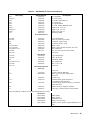
Table 1-1. Agilent Model 59510A and 59511A Specifications
Operating Range: (Both Models)
Agilent Model PARD (mVp-p max).
6032A
20
6033A
20
6038A
20
Inductive Load: 10mH maximum
Note that switching of inductive loads places stresses on the
Agilent 5951XA power relay contacts which can
significantly degrade relay life. It is advisable to switch
these loads under low or zero output conditions, e.g. with
the power supply output disabled. In general, switching any
load under zero output conditions maximizes relay life.
For applications with > 10 mH inductance, consult
Agilent Technologies for applicability and safety.
Using the Agilent 5951XA relays to interrupt high
currents through highly inductive loads will cause
high levels of energy to discharge across the relay
contacts. The resulting rise in temperature and
pressure may cause a breach in the hermeticity of
the seals in the mercury-filled cylinders of the
power relays. Since mercury is a toxic substance,
this is a potentially hazardous condition.
Care should be taken in all applications not to
exceed the operating range specifications in order
to avoid compromising the reliability or the
physical integrity of the mercury-displacement
relays in the Agilent 5951XA.
FOR THESE REASONS, THE AGILENT
5951XA SHOULD NOT BE USED WITH THE
AGILENT 603XA HIGH INDUCTANCE
OPTIONS J01, J02. AND J07.
AC Input: A line select switch on the front panel permits
either 100/120Vac or 220/240Vac operation ( - 13%, +
6% 48-63 Hz).
8
General Information
Isolation:
A IN/B IN to A OUT/B OUT: 200Vdc max.
A IN/B IN/A OUT/B OUT to Ground: ± 500Vdc max.
Agilent 603X LINK to Ground: ± 42Vdc max.
*LOGIC CONTROL/INH to Ground: ± 240Vdc max.
*FLT to Ground: ± 240Vdc max.
FLT to LOGIC CONTROL/INH ±42Vdc max.
The Agilent 603X LINK, LOGIC CONTROL, and
INH signals on the control connector J101 are
referenced to the same common. This means that if
the Agilent 5951XA relay accessory is being used in
the Agilent 603XA configuration (see page 16), these
signals on the control connector J101 must be
restricted to ± 42Vdc from ground, in accordance
with the restrictions of the Agilent 603XA FLT/INH
port float voltage specification (refer to appropriate
Agilent 603XA Operating and Service Manual). The
FLT signal on J101 has its own common which may
float ± 42Vdc from the other; signal common on J101
and up to ± 240Vdc from ground. The LOGIC
CONTROL, INH, and FLT signals may be floated up
to ± 240Vdc from ground ONLY if they are not
driven by or driving signals of the FLT/INH port of
an Agilent Technologies instrument AND the Agilent
603X LINK signals are left disconnected.
As a general rule, if a connection is made from any
point on control connector J101 to any point or the
FLT/INH port of an Agilent Technologies instrument,
all signals on J101 must be restricted to no greaser
than ± 42Vdc from ground.
Settling Time (TTL Control):
Connect: 440 mS
Disconnect: 160 mS
Polarity Reversal: 600 mS
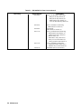
Table 1-1. Agilent Model 59510A and 59511A Specifications (continued)
Maximum Input power: 60VA
PARD: The Agilent 5951XA Relay Accessory incorporates
a filter which, when used with certain models of the
Agilent 603XA power supply family, yields improved
output noise performance at the AOUT/BOUT
terminals of the Agilent 5951XA.
Control Signals Timing:
INH input signal hold time:
1.5 ms minimum
LOGIC CONTROL inputs (TTL levels) hold time:
1.5 ms minimum
INH to FLT propagation: 1.5 ms maximum
Temperature:
Operating: 0 to +55 degrees Celsius
Storage: -40 to +75 degrees Celsius
DC Voltage Drop (at 60A): DC voltage drop of 0.5V
maximum between A IN and A OUT and 0.5V
maximum between B IN and B OUT.
Dimensions: (Both Models)
Width
7.35 in.
186.8 mm
Height
5.14 in.
130.6 mm
Weight (lbs):
59510A
Net Weight:
5
Shipping Weight: 8
Shipping Weight
9
with Option 850:
Depth
7.82 in.
198.6 mm
59511A
8
11
12
Mounting Orientation: ± 10° from vertical
General Information
9
2
Installation
Introduction
This section contains instructions for inspecting and mounting the Relay Accessory, and connecting it to ac power.
Initial Inspection
This accessory was thoroughly inspected and tested before it left the factory. As soon as you receive it, remove it from its
packing case and check to make sure that it has not been damaged in shipment. Check that there are no broken connectors,
etc., and that the unit is free from dents and scratches.
If any damage is found, you should file a claim with the carrier immediately and notify the Agilent Technologies Sales and
Service office nearest you. Keep the original packing materials for the carrier’s inspection or in the event the unit has to be
returned to Agilent Technologies. Warranty information is printed on the inside cover of this manual. Your Agilent
Technologies Sales and Service office will furnish the address of the nearest service office to which the unit can be shipped.
Mounting
The Relay Accessory units utilize mercury displacement relays. Consequently, the units must be
vertically mounted (or oriented) to ensure proper operation and avoid damage to equipment (See Table
1-1 Specifications).
The Relay Accessory unit is convection cooled and can operate without loss of performance within the temperature range of
0 to 55 degrees C. If the unit is to be used on a bench or any flat surface, attach the four adhesive backed rubber feet to the
bottom of the Agilent 5951XA unit. The feet are shipped in a plastic bag along with two quick disconnect plugs and spare
fuses.
The unit can also be mounted in a standard 19 inch rack panel or enclosure. It can be rack mounted in either of two ways:
1.
Drilling two holes in the mounting surface and using screws to engage the threaded inserts in the bottom of the Agilent
5951XA.
2.
Using the Option 850 Rack Mounting Kit.
Ventilation holes are located on both sides of the Agilent 5951XA as well as in the back. Make sure that
the back and at least one side is left unobstructed. Failure to do so could cause overheating and damage.
10 Installation
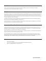
Surface Mounting
The Agilent 5951XA can be mounted against surfaces by means of machine screws. There are two threaded inserts on the
bottom of the Agilent 5951XA (see Figure 2-1). The user must drill two holes in the surface against which the Agilent
5951XA is to be mounted and pass M4 screws (10 mm long) through these holes to engage the threaded inserts within the
Agilent 5951XA. Remember to keep the Agilent 5951XA oriented vertically (see Mounting Orientation in Table 1-1) for
proper operation.
Figure 2-1. Threaded Insert Locations for Surface Mounting
Option 850 Mounting
Rack mount kit Option 850 can be used to mount a single Agilent 5951XA unit on the left or right side of the rack as shown
in Figure 2-2. Two units can be mounted side by side in the rack using two Option 850 kits.
The Agilent 5951XA unit rests on the Option 850 rack as shown in Figure 2-2. Two threaded inserts, located on the bottom
of the Agilent 5951XA, line up with holes in the rack. Use two flat head M4 screws (10 mm long) to secure the unit in the
rack.
Installation 11
Figure 2-2. Option 850 Rack Mounting
Input Power Requirements
You can operate the unit from a nominal 100V, 120V, 220V, or 240V single phase power source at 48 to 63Hz. You can
check the line voltage setting of the unit by examining the LINE SELECT switch S101 setting (see Figure 2-3). You can
change the unit to accept 100, 120, 220, or 240Vac by setting S101 to the 100/120V or 220/240V position. The same rating
fuse (0.5A) is used for a 110,120, 220, or 240Vac input. The fuse, designated F1, is located inside the unit near the LINE
SELECT switch.
Note
12 Installation
The Agilent 5951XA has no on/off switch. To turn the unit on/off, you must connect/disconnect the power
cord.
Figure 2-3. Relay Accessory Front Panel
Power Cord
The unit is shipped from the factory with a power cord that has a plug appropriate for your location. Figure 2-4 shows the
standard configuration of plugs used by Agilent Technologies. Below each drawing is the Agilent part number for the
replacement power cord equipped with a plug of that configuration. If a different power cord is required, contact the nearest
Agilent Technologies Sales and Service office.
Installation 13
Figure 2-4. Available Power Cords
For your protection, the National Electrical Manufacturer’s Association (NEMA) recommends that the unit’s panel and
cabinet be grounded. This unit is equipped with a three-conductor power cord; the third conductor being ground. The unit is
grounded only when the power cord is plugged into the appropriate receptacle. Do not operate this unit without an adequate
cabinet ground connection.
SHOCK HAZARD Connect the power cord to a grounded receptacle before you connect any external
floating voltages to the Relay Accessory.
The offset pin on the standard three-prong power cord connector is the ground connection. If a two-contact
receptacle is encountered, it must be replaced with a properly grounded three-contact receptacle in
accordance with the National Electrical Code, local codes and ordinances. The work should be done by a
qualified electrician.
14 Installation
3
Connections and Operating Information
Introduction
HAZARDOUS MATERIAL The DC power relay(s) in the Agilent 5951XA have a maximum current
rating of 60 amps. The relays contain mercury which is sealed in a steel tube. The tubes may rupture if the
current rating is exceeded. Do not connect the Agilent 5951XA to a power supply capable of delivering more than 60 amps.
This section explains how to make connections and set switches in order to operate the Agilent 5951XA Relay Accessory in
an Agilent 603XA configuration and in a general purpose configuration. The following main discussions are provided:
•
•
•
•
•
Agilent 5951XA Front Panel
DC Power Connections
Sense Lead Connections
Agilent 603XA Configuration
General Purpose Configuration
Agilent 595lXA Front Panel
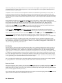
Figure 3-1 illustrates the front panel of the Agilent 5951XA where connections and switch selections are made.
Figure 3-1. Agilent 59510A/59511A Front Panel Connections
Connections and Operating Information 15
DC POWER Connections --
A barrier block (TB1) with four screw-down type terminals connects the input and output
dc power wires. The A IN and B IN terminals are used to connect the Relay Accessory to
the power supply’s + and output terminals, respectively. The A OUT and B OUT
terminals are used to connect the Relay Accessory to the load. See page 3.
SENSE Connections --
A four pin connector J201 (quick disconnect mating plug P201 supplied) connects the
input and output sense leads. The A IN and B IN pins (1 and 2) are used to connect the
Relay Accessory to the power supply’s + S and - S terminals, respectively. The A OUT
and B OUT pins (3 and 4) are used to connect the Relay Accessory to the load’s + and sense leads, respectively. See pages 14 and 15.
Control Connections --
A ten pin connector J101 (quick disconnect mating plug P101 supplied) is provided for
making the following connections:
Agilent 603X LINK(pins 1-2): These two pins provide the serial data link with the
Agilent 603XA supply to control the Relay Accessory (see page 18).
common (pin 3): provides the common connection for the serial data link or the logic
control input.
LOGIC CONTROL (pins 4-6): These three pins are used for connecting TTL compatible
signals to control the Relay Accessory when it is used in a general purpose configuration
(see page 22).
FLT (pins 7 and 8): These two pins are used to connect the fault output line. See page 19
(Agilent 603X configuration) or page 24 (general purpose configuration). Pin 7 is the FLT
output signal, pin 8 is its common.
INH (pins 9 and 10): These two pins are used to connect the inhibit input line. See page
19 (Agilent 603X configuration) or page 23 (general purpose configuration). Pin 9 is the
INH input signal; pin 10 is its common.
CONFIG Switches --
Four switches (S102-1 to 4), each of which can be set to ’’1" or ’’0", make the following
Listen Enable On/Off (S102-1): This switch is meaningful only in the LOGIC CONTROL
mode. With S102-1 set to "0", the Relay Accessory will always respond to the LOGIC
CONTROL lines. With S102-1 set to ’’1’’, the Relay Accessory will only respond to the
LOGIC CONTROL lines when the LISTEN ENABLE input U101-6) is a TTL low level.
S102-1 is factory set to ’’0’’.
Agilent 603X LINK or LOGIC CONTROL (S102-2): This switch selects either Agilent
603X LINK (serial data) or LOGIC CONTROL (TTL levels) as the controlling input. The
"1" position selects the Agilent 603X LINK and the "0" position selects LOGIC
CONTROL. S102-2 is factory set to ’’1’’.
16 Connections and Operating Information
Addresses A1 and A0 (S102-3 and 4): These switches are meaningful only in the Agilent
603X LINK mode to select the address of the Relay Accessory. S102-3 and S102-4 are
both factory set to "0’’. The Agilent 603X power supplies currently will only communicate
with a Relay Accessory at address "0’’. Addresses 1-3 are provided for possible future use.
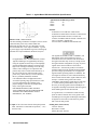
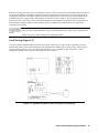
Figure 3-2. DC Power and Sense Lead Connections Remote Sensing
SHOCK HAZARD Turn off input ac power at the power supply and disconnect the Relay Accessory’s line
cord before changing any connections. Make certain that all wires are properly connected, screws are
tightened, and connectors securely installed before reapplying power.
DC Power Connections
The dc power connections between the power supply and the Relay Accessory and between the load and the Relay
Accessory are shown in Figure 3-2. The power supply’s output terminals are connected to the Relay Accessory’s DC
POWER input terminals and the load leads are connected to the Relay Accessory’s DC POWER output terminals as follows:
Relay Accessory
DC POWER Terminal
A IN
B IN
A OUT
B OUT
Connects To
Power Supply +
Power Supply Load +
Load -
The dc power wires are connected to the screw-down terminals on the DC POWER barrier block TB1 as specified above.
Each wire is inserted into the appropriate terminal and the corresponding screw is tightened until the wire is securely
fastened (see Figure 3-1).
Connections and Operating Information 17
To satisfy safety requirements, the wires that connect the power supply output voltage to the Relay Accessory and to the
load should at least be heavy enough not to overheat while carrying the power supply output current that would flow if the
load were shorted. Stranded AWG # 6 copper wire is rated for 50 amps at 105 degrees C conductor temperature. (The
maximum allowable conductor temperature is based on +60 degrees C ambient temperature plus 45 degrees C temperature
rise because of continuous dc current). This is based on use of a twisted pair to connect the load to the power supply output.
Refer to Section III in the applicable Agilent 603XA Operating and Service Manual (see introduction) to help you select the
proper wire size.
Sense Lead Connections
Note
A plastic safety cover for SENSE connector J201 is provided. When the quick disconnect plug P201 is
installed in J201, the plastic safety cover need not be used.
SHOCK HAZARD The safety cover should be installed over J201 to prevent accidentally touching J201
pins when P201 is not installed. Harmful voltages may be present at these pins when power is applied.
Remote Sensing
The sense lead connections shown in Figure 3-2 are for remote sensing. Remote sensing allows the power supply to
automatically increase the output voltage and compensate for the voltage drop in the DC POWER leads. Thus, remote
sensing will help to provide the best possible regulation at the load. This is especially useful for CV operation with loads
that vary and have significant load-lead resistance. For remote sensing, make sure that the straps between the supply’s + and
+ S terminals and between the - and - S terminals are disconnected. The power supply’s sense terminals are then connected
to the Relay Accessory’s input SENSE connector pins and the load sense leads are connected to the Relay Accessory’s
output. SENSE connector pins as follows:
Relay Accessory
SENSE Connector
A IN (J201-1)
B IN (J201-2)
A OUT (J201-3)
B OUT (J201-4)
Connects To
Power Supply + S
Power Supply - S
Load + Sense
Load - Sense
The sense wires are connected to the pins of the SENSE connector mating plug P201 as specified above. Each wire is
inserted into the appropriate pin and the corresponding screw is tightened until the wire is securely fastened (see Figure 3-l).
The plug is then installed in the SENSE connector (J201).
Note
When the Agilent 5951XA Relay Accessory is in the power off state, the SENSE A IN and SENSE B IN
terminals are not connected to any points internally. This means that if there is no other path between the
power supply’s + S/ - S Sense terminals and its + /- output terminals, respectively, the supply’s output may
overshoot. All Agilent Technologies power supplies with the remote sense feature have internal resistors
which provide a moderately high impedance path between the output and sense terminals, and therefore
will not overshoot under these conditions. If the power supply being used is not an Agilent supply and
does not have these internal sense resistors, it is recommended that a resistor of approximately 1 KΩ be
connected between the supply’s + and + S terminals and between the - and - S terminals.
Incorrect wiring of the sense leads or failure to remove the power supply’s own sense straps when using
remote sensing may cause internal protection fuses F201 and F202 to blow requiring fuse replacement
(see Section 5). To avoid nuisance blowing, check all connections before applying power. Also, test
the sensing setup with a low value of power supply output voltage before applying full output voltage.
18 Connections and Operating Information
Because the sensing leads carry only a few milliamperes, the wires used for sensing can be much lighter than the load leads.
The sense leads should be a shielded, twisted pair to minimize noise pickup of external noise. Any noise picked up on the
sensing leads will appear at the supply’s output, and CV load regulation may be adversely affected. The shield should be
grounded at the power supply end only, and should not be used as one of the conductors. The sensing leads should be
connected as close to the load as possible. The shield around these leads should also be grounded at one end only. Refer to
Section III in the applicable Agilent 603XA Operating and Service Manual (see introduction) for more information
concerning remote sensing.
Inadvertent shorting of sense terminals may cause internal (inside Agilent 5951XA) local sense
protection resistors R205 and R206 to open, necessitating replacement. Again, verify connections and
test the
sensing setup at a low output voltage before applying full output.
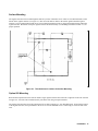
Local Sensing (Figure 3-3)
You can use the DC POWER connect/disconnect and reversing (Agilent 59511A only) features of the Relay Accessory
without using remote sensing connections between the Agilent 5951XA and the load. For local sensing, connect jumpers
between the power supply’s + and + S terminals and between the - and - S terminals as shown in Figure 3-3. In this
configuration, SENSE connector J201 on the Agilent 5951XA is not used.
Figure 3-3. DC Power and Sense Lead Connections, Local Sensing
Connections and Operating Information 19
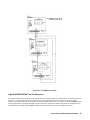
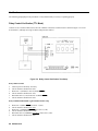
Agilent 603XA Configuration
Before you program the Agilent 603XA/5951XA configuration, complete the general steps outlined below. Each step is
described in greater detail in the referenced paragraph(s). Figure 3-4 illustrates the connections and switch settings required
for the Agilent 603XA/5951XA configuration.
1.
Connect the DC POWER and SENSE leads (pages 3-13 through 3-15).
2.
Ensure that the CONFIG switches on the Agilent 5951XA are selecting Agilent 603X LINK and address 0 (page 16).
3.
Ensure that the RLY LINK/ INH FLT switch on the Agilent 603XA is selecting RLY LINK (page 3-18).
4.
Make the serial data connection between the Agilent 603XA and the Agilent 5951XA (page 3-18).
5.
If desired, you can connect the INH and FLT lines. The remote inhibit (INH) and fault (FLT) lines are described in
detail on pages 19 and 20.
6.
Apply AC power to the Agilent 5951XA and the Agilent 603XA (page 21).
7.
Verify the wiring and switch settings by checking the configuration with a low power supply output voltage before
applying full output voltage.
Note
A switch inside the Agilent 603XA is factory set so that, at power on, the Agilent 603XA/5951XA
configuration ’’wakes-up’’ with the power supply output enabled and disconnected (relay opened) from the
load. See page 18.
Switch Settings
In order to program the Agilent 603XA/5951XA configuration, switches on the Agilent 603XA and the Agilent 5951XA
must be set to the positions shown in Figure 3-4. A small screw driver or ball point pen will be helpful in setting the
switches.
CONFIG Switches
These switches (S102-1 to S102-4) are located on the rear panel of the Agilent 5951XA as shown in Figure 3-1. In order to
program the Agilent 603XA/5951XA configuration, switches S102-3 and S102-4 must select address 0, and switch S102-2
must be set to the Agilent 603X LINK position (’’1").
The address (S102-3, S102-4) must be set to 0 in order for the Agilent 603XA to communicate with the Agilent 5951XA
(addresses 1-3 are provided for possible future use). If S102-2 is not set to the Agilent 603X LINK position, the Agilent
603XA power supply will generate "error 9’’ when it receives a relay command (e.g. RELAY ON) and it will not attempt to
send serial data to the Agilent 5951XA. Also, if the Agilent 603XA expects to send data to the Relay Accessory but does
not receive any response to its communications over the serial data cable, it will also generate "error 9". The switches
S102-2 to S102-4 are read by the Agilent 5951XA only at power-on. Switch S102-1 is only active in the Logic Control
(TTL) mode. For safety considerations, it is recommended that the Agilent 5951XA be unplugged before any of the S102
switches are manipulated.
20 Connections and Operating Information
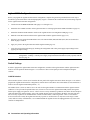
Figure 3-4. Agilent 603X Configuration
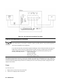
Figure 3-5. Relay Link Connector and Selector Switch on Agilent 603XA Rear Panel
Connections and Operating Information 21
RLY LINK or INH/ FLT Switch
This switch (A8Sl-l), is one of 7 DIP switches located below the GPIB connector on the rear of the Agilent 603XA supply
as shown in Figure 3-5. In order to program the Agilent 603XA/5951XA configuration, switch A8Sl-l must be set to the
RLY LINK position (see Fig. 3-4). With A8Sl-1 set to RLY LINK, connector A8J8 (RLY LINK or INH/FLT) functions as
a serial data link for relay control instead of as a connector for the remote inhibit (INH) input line and the fault (FLT) output
line. If switch A8Sl-l is not set to the RLY LINK position, the Agilent 603XA will generate error 9 when it receives a relay
command (e.g. RELAY ON) and will not attempt to communicate with the Agilent 5951X Relay Accessory via the serial
data cable. The functions performed by the remaining DIP switches A8SI-2 through A8Sl-7 are described in the Agilent
603XA Operating and Service Manual (see page 1).
Agilent 603XA/5951XA Serial Data Connection
The serial data connection is made between connector A8J8 on the rear of the Agilent 603XA supply and the Agilent 603X
LINK connector pins (J101-1 to 3) on the front of the Agilent 5951XA using a shielded cable as shown in Figure 3-6.
The serial data output (A8J8-1) from the Agilent 603XA is connected to the input (J101-1) of the Agilent 5951XA. The
serial data readback (Jl01-2) from the Agilent 5951XA is connected to the input (A8J8-3) of the Agilent 603XA. Note that
pin A8J8-2 is left unconnected. The common connection is made between A8J8-4 and J101-3. The cable shield should only
be grounded (connected to common) at the power supply end (A8J8-4) as shown in Figure 3-6.
A 4-pin quick disconnect mating plug for A8J8 is supplied with the Agilent 603XA supply and a 10-pin quick disconnect
mating plug (P101) for J101 is supplied with the Agilent 5951XA. Each cable wire is inserted into the appropriate mating
plug pins (see Figures 3-5 and 3-6) and the corresponding screw is tightened until the wire is securely fastened.
Figure 3-6. Serial Data Link Cable Connection
Agilent 603XA/5951XA Configuration Wake-Up State
A switch (inside the Agilent 603XA supply) is factory set so that at power-on, the Agilent 603XA/5951XA configuration
’’wakes-up" with the power supply output enabled and disconnected (relay open) from the load. The switch (A7S1) is
located on the power supply’s interface board and can be set to the alternate position in which the Agilent 603X/5951XA
configuration "wakes-up" with the power supply output enabled but connected (relay closed) to the load. Refer to Figure 7-7
and paragraph 5-77 in the Agilent 603XA Operating and Service Manual if you want to gain access to the power supply
interface board A7 in order to change the setting of switch A7S1.
22 Connections and Operating Information
SHOCK HAZARD Changing the setting of switch A7S1-D requires the removal of protective covers. To
avoid the possibility of personal injury, remove the power supply from operation before opening the
cabinet. Turn off ac power and disconnect the line cord, GPIB plug, load, remote sense leads, and INH/FLT
connector before removing protective covers. Refer to the Maintenance section of the appropriate Agilent
603XA Operating and Service Manual for procedures for accessing the A7 PSI Board of the power supply.
Observe all precautions in this section to avoid personal injury or damage to equipment.
As shown in Figure 3-7, A7S1 is comprised of eight separate switches. Switch A7S1-D determines the "wake-up’’ state of
the Relay Accessory. With A7S1-D set to "0", the "wakeup’’ state is relay open. With A7S1-D set to ’’1", the wakeup state is
relay closed. The remaining A7S1 switches are described in the Agilent 603X manual. Note that if you do change switch
A7S1-D, make sure that you do not disturb any of the other A7S1 switch settings. Switches A7S1-E to H are set at the
factory for each particular model and must not be changed.
Figure 3-7. Switch A7S1 (Located inside the Agilent 603X Supply)
Remote Inhibit (INH) and Fault (FLT) Lines
The remote inhibit ( INH ) input (J101-9 and 10) and the fault ( FLT ) output J101-7 and 8) on the Relay Accessory (see
Figure 3-1) are used in place of the INH input and FLT output on the Agilent 603XA power supply in an Agilent
603XA/5951XA configuration. The FLT line provides the user with a means of knowing the status of any unmasked fault
register bit, independently of the service request (SRQ) function available through the GPIB. The INH line controls the
remote inhibit (RI) bit in the power supply’s fault register and provides a way to disconnect the power supply output from
the load. The fault registers are described in detail in the applicable Agilent 603XA Operating and Service Manual (see
page 1). Both INH and FLT are negative true, i.e., they are active when they are low levels. Pins 8 and 10 are the
commons for the FLT and INH signals, respectively. Both FLT and INH may be floated relative to ground and to each
other. Refer to Table 1-1 for details.
Connections and Operating Information 23
INH Input Line
When INH is Low, the Relay Accessory will execute the equivalent of a RELAY OFF command which opens the DC
power relay (normal or reverse) disconnecting the load from the Agilent 603XA output. Also, with INH Low, the Relay
Accessory is in the local sense state, that is, the Agilent 603XA’s + S and - S sense terminals are connected to the Agilent
603XA’s + and - output terminals via the LOCAL SENSE relay contacts inside the Relay Accessory.
The Relay Accessory will not respond to the RELAY ON or OUT ON commands while the INH line is held Low. When
INH goes High, the Relay Accessory will not return to the state previous to the INH Low condition but will remain in the
off state.
While INH is Low, the Relay Accessory will respond to the routine status poll request (see page 20) from the Agilent
603XA by setting a bit in its status response to indicate that a remote inhibit condition exists. The Agilent 603XA will
disable its output upon detection of this condition. The Agilent 603XA output can be enabled again by means of the Agilent
603XA standard command RST (see Section III in the Agilent 603XA Operating and Service Manual). The RST command
should be issued only after the Relay Accessory is no longer remote inhibited (after INH goes High). If RST is issued when
the Relay Accessory is remote inhibited ( INH is Low), the Agilent 603XA and the Agilent 5951XA will remain inhibited.
FLT Output Line
The FLT output line of the Relay Accessory is turned on (Low level) when any unmasked bit in the Agilent 603XA’s fault
register is set. For example, FLT is turned on if the INH input line is turned on and the remote inhibit (RI) bit in the fault
register is unmasked. The RI bit is unmasked using the UNMASK RI command as described in Section III of the Agilent
603XA Operating and Service Manual. If RI was the only fault bit set, the FLT line will go High (off) upon reading the
Agilent 603XA fault register (FAULT?). The other power supply conditions that can turn on the FLT line are discussed in
the Agilent 603XA manual.
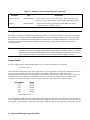
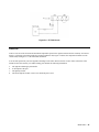
Using INH and FLT with Multiple Agilent 603XA/5951XA’s
Figure 3-8 illustrates three Agilent 5951XA’s (A,B, and C) in which the FLT output of one is connected to the INH input of
the next. Also, the RI bit must be unmasked in each of the Agilent 603XA supplies. A fault condition in any one supply will
cause all of the power supply outputs to be disconnected from their respective loads without computer involvement or any
external circuitry.
SHOCK HAZARD Float voltage restrictions for the INH and FLT signals must be observed to avoid risk
of personal injury or damage to equipment. Refer to the Isolation Specification listed in Table 1-1.
Agilent 603XA Status PoII
The Agilent 603XA queries the status of the Relay Accessory at regular intervals. The state of the RI (remote inhibit) mask
is encoded within the status query. When it receives the status query, the Relay Accessory will be updated according to the
information encoded within the status query. The Relay Accessory will then respond by echoing the status query command
back to the Agilent 603XA with the INH input line state encoded within this echo. The Agilent 603XA may then disable its
output depending upon the remote inhibit information received.
24 Connections and Operating Information
Figure 3-8. FLT/INH Connections
Agilent 603XA/5951XA Turn-On Sequence
The Agilent 603XA queries the status of the Agilent 5951XA at regular intervals as described above. If communications are
broken (e.g., serial data link cable is disconnected) between the Agilent 603XA and the Agilent 5951XA, the Agilent
5951XA will assume a safe state (relay opened), the Agilent 603XA will generate ’’error code 9’’, and the ERROR indicator
on the Agilent 603XA front panel will light. The Agilent 5951XA will resume normal operation when communications are
re-established. The Agilent 603XA ERROR indicator will remain on until the error query (ERR?) is received.
Connections and Operating Information 25
It is recommended that you apply AC power to the Agilent 5951XA first and then turn on the Agilent 603XA power supply.
If the Agilent 603XA is turned on before the 5051XA, "error 9" will be generated. Normal communication between the
Agilent 603X and the Agilent 5951XA will be established after the Agilent 5951XA is turned on. The "error 9" generated
by the Agilent 603X is cleared by sending the error query ’’ERR?". If both the Agilent 603XA and the Agilent 5951XA are
powered up simultaneously, e.g. via the same rack power switch, no error will be generated.
General Purpose Configuration
Figure 3-9 illustrates a general purpose configuration that consists of a power supply, a TTL level control device, the Relay
Accessory, and the load. In order to control the Relay Accessory in this configuration, follow the general steps outlined
below. Each step is described in greater detail in the referenced paragraph(s).
Figure 3-9. General Purpose Configuration
26 Connections and Operating Information
1.
Connect the DC POWER and SENSE leads (pages 13 through 15 ).
2.
Ensure that the CONFIG switches (S102) on the Agilent 5951XA are selecting LOGIC CONTROL (TTL input) and
the desired LISTEN ENABLE position (see page 23).
3.
Make the LOGIC CONTROL (TTL levels) connections (see page 23).
4.
If desired, you can connect the INH and FLT lines (see page 24).
5.
Apply AC power to the Agilent 5951XA unit, the power supply, and the TTL control device.
6.
Verify the wiring and switch settings by checking the configuration with a low power supply output voltage before
applying full output voltage.
Note
At power on, the Relay Accessory ’’wakes-up’’ with its DC power and remote sense relays open, the local
sense relay closed, and with the normal polarity mode in effect. After power is on, the Relay Accessory
goes to the state specified by the LOGIC CONTROL (TTL levels) inputs. If no inputs are connected, the
Agilent 5951XA will remain with the ’’wake-up" conditions in effect.
Switch Settings
In order to control the general purpose configuration, set the CONFIG switches (S102) on the Agilent 5951XA as follows:
Agilent 603X LINK or LOGIC CONTROL Switch
Set switch S102-2 to the LOGIC CONTROL position as shown in Figure 3-9. In this position, the Agilent 5951XA will
respond to the ITL inputs (see pages 23 and 24) and ignore any commands sent via the Agilent 603XA LINK input.
Listen Enable Switch
With S102-1 set to the "0’’ position, the Relay Accessory will continuously respond to signals on the LOGIC CONTROL
input lines. With S102-1 set to "1", the LISTEN ENABLE input (J101-6) determines when the Relay Accessory will
respond to signals on the LOGIC CONTROL lines (see LISTEN ENABLE input).
TTL Input Connections
The TTL control inputs are connected to the LOGIC CONTROL pins J101-3 through J101-6 as shown in Figure 3-9. The
TTL input signals are: OPEN/ CLOSE (J101-4), NORMAL/REVERSE (J101-5), and LISTEN ENABLE (J101-6). The TTL
common connection is made to J101-3.
The LOGIC CONTROL, INH, and FLT signals must be restricted to no greater than ± 42Vdc from ground
unless specific requirements are fulfilled. Refer to the Isolation Specifications in Table 1-1 for details.
Failure to observe these requirements may result in damage to equip1nent and/or personal injury.
Connections and Operating Information 27
LISTEN ENABLE Input.
This input determines if the microprocessor in the Relay Accessory will respond to changes on the TTL input lines. If
LISTEN ENABLE is false (High level), the Relay Accessory will remain in its current state regardless of the state of the
OPEN/ CLOSE and NORM/ REV inputs. When LISTEN ENABLE is held true (Low level), the Relay Accessory will
respond to these inputs.
Switch S102-1 on the rear of the Agilent 5951XA allows the LISTEN ENABLE input to be held Low (true) or to float High
(false). The Relay Accessory is shipped from the factory with S102-1 set to "0" so that LISTEN ENABLE is held Low.
If you want the Relay Accessory to continuously ’’listen’’ for commands on the TTL input lines, leave S102
-1 set to the ’’0"
position. If you want to use the LISTEN ENABLE input to select when the Relay Accessory will "listen" to the TTL input
lines, set S102-1 to "1". With S102-1 set to ’’1" the Relay Accessory will listen only when LISTEN ENABLE (Jl01-6) is true
(Low). This line can be used to control any one of a number of Relay Accessories. Figure 3-10 illustrates the connections
required to control three units. The TTL control device selects the unit by setting the applicable LISTEN ENABLE line (
LE1 , LE2 , or LE3 ) Low.
OPEN/CLOSE Signal
As long as the OPEN/ CLOSE input is held Low, the DC power and remote sense relays will be closed. Releasing the line
(floats High) will open these relays and return the Relay Accessory to the local sense state. (This is assuming that
LISTEN ENABLE is low. If LISTEN ENABLE is high, the Agilent 5951XA will not respond to changes on the
OPEN/CLOSE input, but will remain in its original state.)
NORM/REV Input (Applies only to Agilent Model 59511A).
If the normal polarity power relay K1 and remote sense normal relay K202 are closed, a Low level at this input causes the
relays to go through the open state before they end up in the reverse polarity state (reverse polarity power relay K2 and
remote sense reverse relay K203 both closed). Remember that the NORM/ REV input is level sensitive and must be held
Low in order to keep Relay Accessory in the reverse polarity state. Releasing the line will return the Relay Accessory to the
normal polarity state. (This is assuming LISTEN ENABLE is low. If LISTEN ENABLE is high, the Agilent 59511A will not
respond to changes on the NORM/ REV input, but will remain in its original state.)
Note
Agilent 662X series of GPIB Multiple Output DC Power Supplies equipped with Option 750 provide four
open collector outputs which can provide Low true TTL compatible levels to control the Agilent 5951XA.
Up to four Agilent 59510A’s can be controlled by connecting to the OPEN/ CLOSE input on each Agilent
59510A. Up to two Agilent 59511A’s can be controlled by connecting to the OPEN/ CLOSE and
NORM/ REV inputs on each Agilent 59511A. Refer to the Operating Instructions for the 662XA Option
750 (APPENDIX E, Agilent Part No. 5957-6372).
Remote Inhibit (INH) and Fault (FLT) Lines
In the LOGIC CONTROL (TTL input) mode, a Low level INH signal will always disconnect the power supply output from
the load and cause the FLT line to go true (Low). FLT will go false (High) when INH goes false (High).
A Low level on the INH line will also override the OPEN/ CLOSE line. When the INH line is released (High), the Relay
Accessory will again respond to the OPEN/ CLOSE input provided that the LISTEN ENABLE line is true.! Consequently, it
28 Connections and Operating Information
is recommended that the INH input be driven by a latching type circuit. Activity on the NORM/ REV line while INH is true
(Low) will not affect the Relay Accessory since polarity has no meaning when the DC power relay is opened.
Figure 3-10. Logic Control of Multiple Relay Accessories
Connections and Operating Information 29
4
Agilent 603XA Programming Commands
Introduction
This section describes the commands that have been changed or added to the Agilent 603XA standard commands to permit
programming the Agilent 5951XA/603XA configuration from a GPIB controller. The programming syntax for all of the
commands is described in Section III of the Agilent 603XA Operating and Service Manual (see page 1).
Note
The current Agilent 603XA Option 700 CIIL (control interface intermediate language) programming
capability does not include relay (Agilent 59510A/59511A) control. Control of the Agilent
59510A/5951lA is presently available only in the standard programming language as described in this
section.
The commands are received by the Agilent 5951XA from the Agilent 603XA via the serial data link described in
603XA/5951XA serial data connection. Table 4-1 lists and briefly describes each of the changed and added commands.
Each command is described in greater detail in subsequent paragraphs.
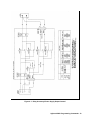
Figure 4-1 illustrates how the power supply’s output and sense leads are connected or disconnected from the load and how
polarity reversal is accomplished. A tabulation is included on Figure 4-1 that specifies how the Agilent 603XA LINK
commands and the LOGIC CONTROL inputs control the DC POWER and SENSE relays in the Relay Accessory.
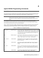
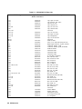
Table 4-1. Additional and Changed Commands
Command
OUT < on/off >
Type
Standard (changed)
Description
Programs both the power supply output and the relay. For on/off = 1 or ON,
the power supply output is disabled, the relay is closed, and then the output
is enabled. For on/off = 0 or OFF, the output is disabled and then the relay
is opened. Having the output off (disabled) when the relay changes state
extends the life of the relay.
OUT?
Standard (changed)
Queries the power supply output setting independent of the actual power
supply output state or the state of the relay. The response is either OUT 1
(setting = output enabled) or OUT 0 (settling = output disabled).
POL < norm/rev >
Standard (added)
Instructs the Relay Accessory (Agilent 59511A only) to provide either
normal polarity (norm/rev = NORM or 1) or reverse polarity (norm/rev =
REV or 0) at the load.
POL?
Standard (added)
Queries the relay polarity setting (Agilent 59511A only). The response is
either POL 0 (setting = polarity reversed) or POL 1 (setting = polarity
normal).
DC < on/off >
Standard (added)
On/off = 0 or OFF turns off the power supply output (disables the power
mesh). On/off = 1 or ON turns on the power supply output (enables the
power mesh). The DC <on/off> command does not affect the state of the
relay.
DC?
Standard (added)
Queries the power supply output setting. The response is either DC 0
(setting = output disabled) or DC 1 (setting = output enabled).
Agilent 603XA Programming Commands 31
Table 4-1. Additional and Changed Commands (continued)
Command
Type
Description
RELAY < on/off >
Standard (added)
Opens (on/off = OFF or 0) or closes (on/off = ON or 1) the relay. The
RELAY <on/off> does not affect (turn on/off) the power supply output.
RELAY?
Standard (added)
Queries the relay setting. The response is either RELAY 0 (setting =
opened) or RELAY I (setting = closed).
Changed Command
The actions performed by the Output on/off command (see Table 3-7 in the Agilent 603X Operating and Service Manual)
have changed. The Output on/off and the added commands (e.g., Relay on/off) described later can be used to control the
Relay Accessory provided that the RLY LINK-INH/FLT switch A8S1-1 is in the RLY LINK position. Using the output
command is the preferred method because it disables the power supply’s output while the relays are switched, thus
prolonging relay life.
Note
When the RLY LINK-INH/FLT switch A8S1-1 on the Agilent 603X power supply is in the INH/FLT
position, the functions of the Output command and the other standard commands are same as described in
Table 3-7 of the Agilent 603X Operating and Service Manual. The added commands (DC on/off, Relay
on/off, and Polarity norm/rev) will generate error 9 if sent with A8S1 in the INH/FLT position.
Output On/Off
The power supply output is enabled/disabled and the relay closed/opened using the OUT command:
OUT ON or OUT 1
This command first disables the power supply output, delays to permit the output to downprogram sufficiently, then closes
the power relay, and finally, after a delay to guarantee relay settling, enables the power supply output. The
downprogramming delay depends upon the model as specified below. The OUT ON (or OUT 1) command also places the
Agilent 603XA/5951XA configuration in the remote sense state. In the remote sense state, the power supply’s sense
terminals are connected to the load’s sense leads via the remote sense relay contacts in the Agilent 5951XA.
Agilent Model
6030
6031
6032
6033
6038
Delay
600 mS
500 mS
400 mS
200 mS
400 mS
OUT OFF or OUT 0
This command first disables the power supply output and then opens the relay after the specified delay. The OUT OFF (or
OUT 0) command also places the Agilent 603XA/5951XA configuration in the local sense state. In the local sense state, the
power supply’s sense terminals are connected to the supply’s output terminals via local sense relay contacts in the 5951XA.
32 Agilent 603XA Programming Commands
Figure 4-1. Relay Accessory/Power Supply Output Control
Agilent 603XA Programming Commands 33
Note
The delays between disabling the output of the power supply and the closure or opening of the relay
contacts do not guarantee that the current is zero during relay closure or opening. The delays were chosen
to provide reasonable reduction in output before relay contact activity in order to prolong relay life. In
applications where it is necessary to guarantee zero output conditions, e.g. when using highly inductive
loads, it is advisable to use the DC On/Off and RELAY On/Off commands with a suitable WAIT between
them. In general, to extend relay life, it is advisable to switch the relays under low or zero output
conditions.
The state of the Output on/off setting may be read by sending:
OUT?
and addressing the power supply to talk. The response from the power supply is in the format:
OUT 0 or OUT1
in which 0 indicates the power supply output setting is disabled; and 1 indicates that the supply output setting is enabled.
Note that the actual output state may not be reflected. For example, if the setting is output enabled, but an overvoltage
condition has caused the output to be disabled, an OUT? query will return OUT 1.
Added Commands
Relay on/off, DC on/off, and Polarity on/off commands have been added to the Agilent 603XA standard programming
commands in order to control the Agilent 5951XA/603XA configuration. The DC on/off and Relay on/off commands allow
independent control of the power supply output and the relays. An Output command, issued after a Relay and/or DC
command(s), will supersede these command(s) and restore both the power supply output and the relays to the same state
(e.g. power supply output enabled and relay closed).
At power-on, the default states are power supply output enabled (DC ON) and relay opened (RELAY OFF). These default
states can be reconfigured on Agilent 603XA supplies by changing one of the A7S1 identification switches on the power
supply interface board (see 603XA/5951XA configuration wake-up state). The alternate power-on default setting is power
supply output enabled (DC ON) and the relay closed (RELAY ON).
The power-on default state for the Polarity on/off command is normal polarity (POL NORM). The POL command only
applies to Agilent Model 59511A. If it is used to program an Agilent 603XA/59510A configuration, programming error 9
will be generated by the Agilent 603XA supply when it attempts to execute the POL command.
DC On/Off
The power supply output is enabled/disabled without affecting the state of the Relay Accessory using the DC command:
DC ON or DC 1
The DC ON command enables the power supply output.
DC OFF or DC 0
The DC OFF command disables the power supply output. When disabled the output is approximately zero volts.
The state of the DC on/off setting may be read by sending:
34 Agilent 603XA Programming Commands
DC?
and addressing the power supply to talk. The response from the power supply is in the format:
DC 0 or DC 1
in which 0 indicates that the power supply output setting is disabled, and 1 indicates that the power supply output setting is
enabled. Note that the DC ? command returns the state of the power supply output setting as controlled by the DC or OUT
commands.
Relay On/Off
The relay is closed/opened using the RELAY command:
RELAY ON or RELAY 1
The RELAY ON command closes the relay connecting the power supply’s output to the load. It also places the supply in the
remote sense state.
RELAY OFF or RELAY 0
The RELAY OFF command opens the relay disconnecting the power supply’s output from the load. It also places the supply
in the local sense state.
The state of the Relay on/off setting may be read by sending:
RELAY?
and addressing the power supply to talk. The response from the power supply is in the format:
RELAY 0 or RELAY 1
in which 0 indicates that the relay setting is opened, and 1 indicates that the setting is closed. Note that the RELAY?
command returns the setting of the relay as controlled by the RELAY and/or OUT commands. A relay opened due to the
remote inhibit (INH) signal will not affect the response to RELAY?. A low level inhibit (INH) signal will always cause the
relay to open. For example, if a RELAY ON command has been sent to close the relay and then an INH signal opens the
relay, a subsequent RELAY? command will result in a response of RELAY 1 indicating that the relay is programmed to be
closed, although it is actually open.
Polarity Normal/Reverse (Model 59511A only)
The polarity of the power supply output voltage at the load is changed using the POL command:
POL NORM or POL 1
POL NORM disables the power supply output, changes the output polarity setting to normal (opens the reverse polarity
relays and closes the normal polarity relays), and then enables the power supply output.
POL REV or POL 0
POL REV disables the power supply output, changes the output polarity setting to reverse (opens the normal polarity relays
and closes the reverse polarity relays), and then enables the power supply output.
Agilent 603XA Programming Commands 35
Note
If the polarity is already that which is called for by the POL command, there will be no change in the
power supply output or the state of the relay.
The power-on default is normal polarity. If the 603XA power supply’s output is enabled and one of the relays (normal or
reverse) is closed when the 603XA receives a POL command to reverse polarity, the 603XA will do the following:
1.
2.
3.
Disable its output.
Wait for the output to decay (the delay is model dependent, see page 28).
Open the relay.
The above sequence places the 603XA/59511A configuration in the OUT OFF state (power supply output off and relays
opened). Immediately after the relays have settled in the opened state, the sequence is reversed until the resultant state is
OUT ON, with the output enabled and the relay for the opposite polarity closed.
The state of the POL (normal/reverse) setting may be read by sending:
POL?
and addressing the power supply to talk. The response from the power supply is in the format:
POL 0 or POL 1
in which 0 indicates that the polarity setting is reversed, and 1 indicates that the polarity setting is normal.
36 Agilent 603XA Programming Commands
5
Maintenance
Introduction
This section provides verification, circuit operation, and troubleshooting information for the Agilent Model 59511A and
59510A Relay Accessories. Before you attempt to troubleshoot the Relay Accessory, ensure that the fault is with the Agilent
5951XA itself and not with the GPIB controller, Agilent 603XA supply, or power line. The verification tests that follow in
relay control verification (TTL mode) enable this to be determined without having to remove the covers from the Relay
Accessory.
It is recommended that you read the circuit descriptions in circuit operation paragraphs as well as the operating information
and programming instructions in Sections 3 and 4 before you troubleshoot the unit.
This section also contains a replaceable parts list, functional schematic, and a component location diagram.
Circuit Operation
The Agilent 59510A and 59511A Relay Accessories can be used in power supply applications where either or both load
connect/disconnect and polarity reversal are required. The Agilent 59510A provides for load connect/disconnect for both
the power output and the sense leads of the supply. The Agilent 59511A provides for polarity reversal as well as for load
connect/disconnect for both power output and sense leads.
Figure 5-7 at the back of this manual is a functional schematic diagram that illustrates the circuits contained on the main
circuit board, the relay board, and on the chassis of the Agilent 59510A/59511A Relay Accessory.
Main Circuit Board
The main circuit board contains the circuits which control the sense and power relays. A power-on circuit and bias supply
which provide power to operate the control circuits and the relays are also located on the main circuit board.
Control Circuits
Microcomputer chip U101 is the primary component. It includes a microprocessor unit (MPU), ROM, and RAM. These
internal circuits process all relay commands that are received via the serial data input or the general purpose TTL input.
Ceramic resonator Y101 provides a 4 MHz clock signal for the microprocessor. The jumper across J103 -5 and J103-6
identifies the unit as Agilent Model 59510A. No jumper connected identifies the unit as Agilent Model 59510A.
When CONFIG switch S102-2 is set to "1’’, it selects the Agilent 603X LINK (serial data) input and allows the
microprocessor to respond to serial data from the Agilent 603X and ignore the TTL input.
Comparator U103D is used as a level sense amplifier for the serial data which represents commands from the GPIB
controller. Microprocessor U101 converts the serial data into signals to open or close the DC power and sense relays via
high current driver circuits U104 and U105. Quad driver U104 controls the normal output polarity (drivers A and B),
remote sense reverse (driver C), and local sense (driver D) relays. Quad driver U105 controls the reverse output polarity
(drivers A and B) and remote sense normal (driver C) relays. Driver D of U105 is used for the FLT output line. The normal
Maintenance
37
and reverse polarity DC power relays each have two drivers because of their higher current requirements. Optical isolator
U108 transfers the FLT signal to connector pins J101-7 and 8. The microprocessor’s FLT output and INH input lines are
described in Section 3 of this manual.
Comparator U103C is used as a level sense amplifier to readback serial data which represents Relay Accessory status. As
described in 603XA status poll, the Agilent 603XA queries the status of the Relay Accessory at regular intervals. If the
microprocessor does not receive any communication within this interval, it will reset and the Agilent 5951XA will assume a
safe state (relay open). Counter U109 divides the microprocessor clock to a rate used by the serial communications circuitry
inside U101.
With CONFIG switch S102-2 set to the LOGIC CONTROL (TTL levels) input ("0" position), the microprocessor will
respond to the TTL inputs, OPEN/ CLOSE and NORM/ REV (Agilent 59511A only), and ignore any commands received on
the serial data input. Each TTL input line has a pull-up resistor to make the default input a logic High causing the
microprocessor to open the DC power and remote sense relays and close the local sense relay. The microprocessor
translates the OPEN/ CLOSE and NORM/ REV TTL inputs into signals that open/close the DC power and remote sense
relays as described in LISTEN ENABLE input and OPEN/CLOSE signal paragraphs.
A third TTL input, LISTEN ENABLE , determines (in the logic control mode) if the microprocessor will respond to
OPEN/ CLOSE and NORM/ REV inputs. If LISTEN ENABLE is false (high level), the microprocessor will keep the relays
in their current state regardless of the state of the OPEN/ CLOSE and NORM/ REV inputs. When LISTEN ENABLE is held
true (low level), the microprocessor will respond to the other TTL inputs. CONFIG switch S102-1 allows the
LISTEN ENABLE input to be held Low (logic true) or float high (logic false). S102-1 is factory set to "0’’ (low, logic true).
Switches S102-3 and S102-4 are address switches which are meaningful only in the Agilent 603X LINK mode (when
S102-2 is set to "1"). Switches S102-3 and S102-4 are factory set to "00’’ because at present, Agilent 603XA supplies will
only communicate with a Relay Accessory at address 0. Addresses 1-3 (selectable by changing S102-3 and S102-4 to "01",
"10", or "11") are provided for possible future use.
Bias Supply.
The bias supply is comprised of full-wave bridge rectifier diodes U106, a switching regulated power supply (Q101-Q103
and U102), and a three-pin regulator IC Q104. The ac input power is applied to U106 via line fuse F1, line voltage select
switch S101, and transformer T101. Transformer T101 provides 36Vac nominal across U106. The switching regulated
supply generates +11.5Vdc for the current drivers (U104,U105), comparators (U103), and the relays (K1, K2, K201 -K203).
A feedback loop containing comparator U102A and driver transistors Q101, Q102 control the conduction of Q103 to keep
the 11.5Vdc bias output constant. The 11.5Vdc output is fedback to U102A where it is compared with a reference voltage.
If the output goes below 11.5V, Q103’s duty cycle is increased to increase the output. Conversely, if the output rises above
11.5V, Q103’s duty cycle is decreased which in turn decreases the output.
The 11.5V output is also applied to three-pin voltage regulator Q104 and to the power-on (PON) circuit. Voltage regulator
IC Q104 generates the + 5V bias which is used by various control circuits on the main circuit board.
Power-on Circuit.
The power-on circuit (U103A, U103B, U107) generates the PON signal when power is initially turned on. The PON signal
is held low for approximately 100 ms at power on to initialize microprocessor U101 and counter U109 and to initially
inhibit the relay driver circuits (U104, U105). This prevents any erroneous relay control signals from being generated when
power is initially applied to the Relay Accessory.
Also, if the line voltage drops after the unit has been turned-on, the power-on circuit will again generate the PON Low level
signal to initialize the microprocessor and inhibit the relay drivers.
38 Maintenance
Relays
As shown in Figure 5-5, the sense relays K201-203 (mercury-wetted) are located on the relay board and the DC power
output relays K1, K2 (mercury displacement) are mounted vertically in the chassis.
Agilent Model 59511A contains five relays: K1 (DC power normal polarity), K2 (DC power reverse polarity), K201 (local
sense), K202 (remote sense normal polarity), and K203 (remote sense reverse polarity). The relays are controlled by
microprocessor U101 via relay drivers U104 and U105 as shown in Figure 5-6. A summary of the commands that control
relay operation is given in Table 4-1.
Normal DC output polarity (NORM) relay K1 connects/disconnects the + and - power supply output terminals to the load
and the remote sense normal polarity (RSN) relay K202 connects/disconnects the + and - sense leads from the load to the +
S and - S terminals on the power supply. When reverse polarity is programmed, relays K2 and K203 are operated to reverse
the polarity of the connections/ disconnections described above. Microprocessor U101 sequences the closing/opening of the
relays to minimize overshoots at the power supply output. Resistors R301-306 and capacitors C301-3306, mounted on the
filter board, provide noise filtering and ESD (electrostatic discharge) protection at the DC POWER terminals.
Note that local sense (LS) relay K201 is closed when the other relays are opened. Fuses F201 and F202 in the remote sense
lines prevent excessive current from flowing through the sense path in the event of relay failure or miswiring of sense leads.
Resistors R205 and R206 provide excess current protection for the local sense relay. Resistors R201-204, 211-224 and
capacitors C201-204 provide ESD protection at the sense terminals.
Agilent Model 59510A is identical to Agilent Model 59511A except that it does not contain relays K2 and K203. Thus, the
reverse polarity functions described above do not apply to Agilent 59510A. If a command that controls polarity is sent to
the Agilent 59510A, a programming error will be generated by the Agilent 603XA when it attempts to execute the
commands. Figure 5-1 shows the relay timing sequence. This timing sequence insures that the sense signal path remains
unbroken when the power relay is switched.
Figure 5-1. Relay Timing
Maintenance
39
Verification
The following paragraphs provide procedures to verify that the Relay Accessory is operating properly.
Relay Control Verification (TTL Mode)
Connect 5Vdc, a 100 ohm l/2W resistor, and a dc voltmeter to the Sense connector J201 as shown in Figure 5-2. Set all
S102 switches (1 through 4) to logic 0 (down) and proceed as follows:
Figure 5-2. Relay Control Verification Test Setup
Relay OPEN/CLOSE
a.
b.
c.
d.
e.
f.
Turn-on power to the Relay Accessory.
The dc voltmeter should read 0 volts.
Short J101-3 (common) to J101-4 (OPEN/ CLOSE ).
The dc voltmeter should read 5 volts.
Disconnect J101-3 (com) from J101-4 (OPEN/ CLOSE ).
The dc voltmeter should read 0 volts.
Relay NORMAL/REVERSE (Agilent Model 59511A Only)
a.
b.
c.
d.
e.
f.
Short J101-4 (OPEN/ CLOSE ) TO J101-3 (com).
The dc voltmeter should read 5 volts.
Short J101-5 (NORMAL/ REVERSE ) TO J101-3 (com).
The dc voltmeter should read - 5 volts.
Disconnect J101-5 (NORMAL/ REVERSE ) from J101-3 (com).
The dc voltmeter should read 5 volts.
40 Maintenance
Relay LISTEN ENABLE
a.
b.
Set S102-1 to logic 1 (up).
Short J101-6 ( LISTEN ENABLE ) to J101-3 (com).
c.
d.
e.
f.
g.
h.
i.
j.
k.
The dc voltmeter should read 0 volts.
Short J101-4 (OPEN/CLOSE) to J101-3 (com).
The dc voltmeter should read 5 volts.
Disconnect J101-6 ( LISTEN ENABLE ) from J101-3 (com. )
The dc voltmeter should read 5 volts.
Disconnect J101-4 (OPEN/CLOSE) from J101-3 (com).
The dc voltmeter should read 5 volts.
Momentarily short J101-6 ( LISTEN ENABLE ) to J101-3 (com . )
The dc voltmeter should read 0 volts.
Relay Agilent 603XA LINK/LOGIC CONTROL
a.
b.
c.
d.
e.
f.
g.
h.
i.
Set S102-2 to the Agilent 603XA LINK position (logic 1, up).
Turn off power to the Relay Accessory for 10 seconds.
The dc voltmeter should read 0 volts.
Short J101-4 (OPEN/ CLOSE )to J101-3 (com).
The dc voltmeter should read 0 volts.
Set S102-2 to the LOGIC CONTROL position (logic 0, down).
The dc voltmeter should read 0 volts.
Turn off power to the Relay Accessory for 10 seconds.
The dc voltmeter should read 5 volts.
DC Power Relay Verification
Connect 5Vdc, a 100 ohm ½ W resistor, and a dc voltmeter to the DC Power terminal block TB1 as shown in Figure 5-3.
Set all S102 switches (1 through 4) to logic 0 (down) and proceed as follows:
Output Normal Relay
a.
b.
c.
d.
e.
f.
Turn on power to the Relay Accessory.
The dc voltmeter should read 0 volts.
Short J101-3 (com) to J101-4 (OPEN/ CLOSE ).
The dc voltmeter should read 5 volts.
Disconnect J101-3 (com) from J101-4 (OPEN/ CLOSE ).
The dc voltmeter should read 0 volts.
Output Reverse Polarity Relay (Agilent Model 59511A only)
a.
b.
c.
d.
e.
f.
Short J1014 (OPEN/ CLOSE ) to J101-3 (com).
The dc voltmeter should read 5 volts.
Short J101-5 (NORMAL/ REVERSE ) TO J101-3 (com).
The dc voltmeter should read - 5 volts.
Disconnect J101-5 (NORMAL/ REVERSE ) from J101-3(com).
The dc voltmeter should read 5 volts.
Maintenance
41
Figure 5-3. DC Power Relay Verification Test Setup
Removal and Replacement Procedures
HAZARDOUS MATERIAL Relays K1 (Agilent 59510A and Agilent 5951lA) and K2 (Agilent 59511A
only) contain mercury. The mercury is sealed in a stainless steel tube. Defective relays must be disposed in
accordance
with your local hazardous waste regulations.
If you wish, the relays may be returned to Agilent Technologies. If the seal has been broken, the relays and
liquid mercury must be placed in a leakproof plastic bag. Place the bag in a fiberboard box and return to
Agilent Technologies by surface transportation only. If the seal is not broken, the plastic bag is not
necessary. Please ship relays to:
Agilent Technologies
150 Green Pond Rd
Rockaway, N.J. 07866
Attn: Product Support Group
The following paragraphs describe how to remove the assemblies and components within the Relay Accessory. Figure 5-5
illustrates the location of the circuit boards and chassis mounted components. Figure 5-5 illustrates the component locations
on each circuit board. Replacement procedures are essentially the reverse of the removal procedures. Unplug the line cord
and proceed as follows:
Cover
To remove the cover:
a.
b.
Remove the two cover screws, one on each side
Lift the cover straight up and off of the unit.
42 Maintenance
Note
When replacing the cover, put it back on the same way that you removed it in order for the cover screw
holes to line up with the chassis screw holes.
Assembly Removal
To disassemble the unit:
a.
b.
c.
d.
e.
f.
g.
Remove the plastic safety cover and quick disconnect plugs from the front panel connectors.
Disconnect the ribbon cable from J202 on the Sense Relays Board.
Remove two screws securing the DC POWER terminal block (TB1) to the front panel.
Remove two screws securing the 3-sided upper chassis to the front panel. The screws are located on the left and right
side top corner.
Remove two screws securing the upper chassis to the lower chassis. The screws are located at the bottom on the rear of
the unit.
Push TB1 through the opening in the Front Panel and separate the upper chassis from the front panel and lower chassis
which houses the main circuit board. The upper chassis contains the sense relays board, TB1, filter board, and the dc
power relay (s).
You can remove individual assemblies (circuit boards) and components (e.g. power relay) from the upper chassis by
disconnecting the applicable wires and attaching hardware.
Main Circuit Board Removal
To remove the main circuit board:
a.
b.
c.
Remove the two screws and nuts that secure the ac input connector/line filter to the front panel.
Remove the two screws that secure the main circuit board to the chassis.
Remove the main circuit board.
Troubleshooting Procedures
The troubleshooting procedures provided in the following paragraphs should be performed in the sequence given in order to
isolate the defective circuit and/or component. Refer to Figures 5-4 through 5-7 and proceed as described below.
SHOCK HAZARD The troubleshooting procedures given below are performed with power applied and
the protective cover removed. Such procedures should be performed only by service-trained personnel who
are aware of the hazards (for example, fire and electrical shock).
Test Setup
To gain access to the circuit boards and components inside the unit:
a.
b.
c.
d.
Remove the cover and disassemble the unit as described in Cover and Assembly Removal paragraphs.
Place the disassembled unit on a flat surface so that the component side of the main circuit board is accessible. Place
the upper chassis so that you can reconnect the ribbon cable.
Reconnect the ribbon cable between J202 on the sense relays board and J102 on the main circuit board.
Reconnect the line cord and turn on power by plugging the line cord into the ac line.
Maintenance
43
Bias Supply and Power-On Circuit
a.
b.
Check the ac line fuse F1.
Check the bias voltages at the test points shown on Figure 5-6:
Test Point
TP1 (pos) to TP2 (com)
TP3 (pos) to TP2 (com)
TP4 (pos) to TP2 (com)
Measurement
+5Vdc ± 0.25Vdc
+11.8Vdc ± 0.5Vdc
+55Vdc ±10Vdc
If the bias voltages are incorrect, check the waveforms at test points TP5, TP6, and TP7 (see Figure 5 -6) to isolate the faulty
components.
*t = approx. 1.4ms with sense relays board disconnected
t = approx. 0.8ms with sense relays board connected
t = approx. 0.12ms with power relay energized
c.
Check the power-on ( PON ) signal. The PON signal is false (high) during normal operation. Check for PON false
(high) at U101-6, U109-11, U104-14, and U105-14. If PON is true (low), check U103 and U107, see Figure 5-7.
Microprocessor U101
a. Check if the microprocessor passes the power-on self-test by measuring, the signal at U101-19:
Measured Signal
Low level
250Hz
500Hz
1KHz
44 Maintenance
Meaning
Microprocessor U101 passed self test
RAM failure; replace U101
ROM failure; replace U101
Timer failure; replace U101
2KHz
ID failure; Make sure that the J103 ID connector configuration is correct. For Agilent Model
59510A, all J103 pins should be open. For Agilent Model 59511A, pins 5 and 6 should be shorted
(see Figure 5-7). If J103 configuration is correct and the signal is 2 kHz, replace U101.
b. Check the microprocessor clock signals at:
Test Point
U101-2, 3
U101-40
U101-10
Clock Signal
4MHz sine wave
1MHz square wave
125KHz square wave
c. Turn off power.
Relay Circuits
Note
Check sense protect resistors R205 and R206 and sense protect fuses F201 and F202 before
troubleshooting individual sense relay circuits.
The following procedures troubleshoot the relay control circuits and the relays (Figure 5-7). To troubleshoot these circuits,
set the CONFIG switches S102-2 to ’’0" (LOGIC CONTROL) and S102-1 to ’’0’’ (LISTEN ENABLE).
Agilent Model 59510A.
Proceed as follows:
a.
Turn on power and check that relay K201 is energized (contacts closed) and relays K1 and K202 are deenergized
(contacts opened). If the relays are not in the state specified, check if the correct levels are present at the applicable
driver output pins as follows:
Relay
K1 (opened)
K202 (opened)
K201 (closed)
b.
Driver Output Pin
U104-1 and 3
U105-6
U104-8
Level
11.5V
11.5V
0V
Connect the OPEN/ CLOSE input (J101-4) to common (J101-3) and check that relays K1 and K202 are energized
(contacts closed) and relay K201 is deenergized (contacts opened). If the relays are not in the state specified, check if
the correct levels are present at the applicable driver pins are as follows:
Relay
K1 (closed)
K202 (closed)
K201 (opened)
Driver Output Pin
U104-1 and 3
U105-6
U104-8
Level
0V
0V
11.5V
Agilent Model 59511A.
Proceed as follows:
a.
Turn on power and check that relay K201 is energized (contacts closed) and relays K1, K2, K202, and K203 are
deenergized (contacts opened). If the relays are not as specified, check if the correct levels are present at the applicable
driver pins as follows:
Maintenance
45
Relay
K1 (opened)
K2 (opened)
K202 (opened)
K203 (opened)
K201 (closed)
b.
Level
11.5V
11.5V
11.5V
11.5V
0V
Connect the OPEN/ CLOSE input (Jl01-4) to common (Jl01-3) and check that relays K1 and K202 are energized
(contacts closed) and relays K2, K201, and K203 are deenergized (opened). If the relays are not as specified, check if
the correct levels are present at the applicable driver pins as follows:
Relay
K1 (closed)
K2 (opened)
K202 (closed)
K203 (opened)
K201 (opened)
c.
Driver Output Pin
U104-1 and 3
U105-1 and 3
U105-6
U104-6
U104-8
Driver Output Pin
U104-1 and 3
U105-1 and 3
U105-6
U104-6
U104-8
Level
0V
11.5V
0V
11.5V
11.5V
With the OPEN/ CLOSE input J101-4 still connected to J101-3, also connect the NORM/ REV input (J101-5) to
common (J101-3). Check that relays K2 and K203 are energized (contacts closed) and relays K1, K201, and K202 are
deenergized (contacts opened). If the relays are not as specified, check if the correct levels are present at the applicable
driver pins as follows:
Relay
K1 (opened)
K2 (closed)
K202 (opened)
K203 (closed)
K201 (opened)
Driver Output Pin
U104-1 and 3
U105-1 and 3
U105-6
U104-6
U104-8
Level
11.5V
0V
11.5V
0V
11.5V
FLT and INH Circuits
To troubleshoot these circuits, leave the LOGIC CONTROL mode in effect (S102-2 set to "0") and proceed as follows:
a.
Connect a LED (Agilent/PN 1990-0486 or equivalent), a 3K resistor (Agilent/PN 0686-3025 or equivalent), and an
external 5Vdc supply (Agilent/PN 6214C or equivalent) to the FLT output pins (J101-7 and 8) as shown in Figure 5-4.
b.
Set the INH input true by connecting the INH input (Jl01-9) to common (J101-10). In the LOGIC CONTROL mode,
when the INH input goes true (low), the FLT output goes true (Low).
c.
Check that the LED is on. If it is on, go to step d. If it is not on, check the level at U105-8. If it is 0 V (approx.), U108
is probably defective. If it is 4V (approx.), U105 is probably defective.
d.
Set the INH input false by disconnecting the jumper between J101-9 and J101-10.
e.
Check that the LED is out. If it is not out, check the level at U105-8. If the level is 4V (approx.), U108 is probably
defective. If it is 0V (approx.), U105 is probably defective.
46 Maintenance
Figure 5-4. FLT/INH Circuit
Parts List
Table 5-1 lists all of the electrical and mechanical replaceable parts for the Agilent 59510A and 55511A Relay Accessories.
Figure 5-5 shows the circuit board and relay locations within the unit, Figure 5-6 shows the component locations on each
circuit board, and Figure 5-7 is the functional schemation.
You can order parts from your local Agilent Technologies sales office. Refer to the list of sales offices at the back of the
manual for the office nearest you. When ordering parts include the following information:
a.
b.
c.
d.
The Agilent Technologies part number.
A description of the part.
The quantity needed.
The model Agilent 59510A or 59511A in which the part is used.
Maintenance
47
Table 5-1. 59510A/59511A Parts List
Ref. Desig.
C101
C102
C103
C104
C105,109
C106
C107, 108
C110-112
C113,114
C115,116
C117
CR101
CR102
F1
J101
J102
J103
L101
Q101
Q102
Q103
Q104
R101
R102
R103
R104
R105
R106,110,127,128
R107
R108
R109
R111
R112,117,129,131-134
R113
R114,115
R116,135
R118
R119
R120
R121-124
R125,126
R130
S101
S102
T101
U101
U102
48 Maintenance
Agilent Part No.
Main Circuit Board
0160-4788
0160-4833
0180-0376
0180-2980
0180-0291
0180-3853
0160-4835
0160-4787
0160-4281
0180-0405
1901-1087
2110-0803
0360-2348
1251-8542
1251-8736
9140-1186
1853-0510
1854-0575
1854-0920
1826-0122
0683-1235
0747-0835
0698-0085
0698-3382
0699-0070
0757-0442
0757-0400
0757-0280
0757-0726
0698-3260
0757-0401
1810-0316
0757-0472
0812-0010
1810-0337
0683-1215
0698-3149
0757-0449
0698-6286
3101-2609
3101-2264
9100-4704
5080-2127
1826-0412
Description
Cap, 18pF 5% 100V
Cap, 0.022µF 10% 100 V
Cap, 0.47µF 35V
Cap, 1000µF 35V
Cap, 1µF 10% 35V
Cap, 1000µF 100V
Not Used
Cap, 1µF 10% 50V
Cap, 22pF 5% 100V
Cap, 2200pF 20%
Cap, 1.8µF 10% 20V
Not Used
Diode rectifier
Fuse, 0.5 A, 250V time delay(ac line)
Right angle connector, 10 pins (control)
Connector, header, 7 pins
Connector, header, 6 pins (model ID)
Inductor 680µH
Transistor, PNP
Transistor, NPN
Transistor, NPN
IC Volt Reg UA7805UC
Res, 12K 5% 1/4W
Res, 6.81K 1% 1/2W
Res, 2.61K 1%
Res, 5.49K 1%
Res, 3.16M 1%
Res, 10K 1% 1/8W
Res, 90.9 1% 1/8W
Res, 1K 1% 1/8W
Res, 511 1% 1/8W
Res, 464K 1%
Res, 100 1% 1/8W
Resistor network (8 X 10K)
Res, 200K 1%
Res, 3K 5% 3W
Resistor network (8 X 4.7K)
Res, 120 5% 1/4W
Res, 255K 1%
Res, 20K 1% 1/8W
Res, 100M 10%
Not Used
Switch, DPDT
Switch, rocker (4)
Transformer, power
IC, microprocessor unit
IC, comparator
Table 5-1. 59510A/59511A Parts List (continued)
Ref. Desig.
U103
U104,105
U106
U107
U108
U109
VR101
VR102-107
VR108
Y101
C201-204
F201,202
J201
J202
K201, 202,203*
K211, 222,233*
R201-204,211-214
R205,206
R207-210
C301-304
C305-306
J301
R301-304,311-314
R305,306
R307-310
Agilent Part No.
1826-0138
1820-4185
1906-0006
1826-1343
1990-0543
1820-3205
1902-3180
1902-0950
1902-0556
0410-1627
Sense Relays Board
0160-7026
2110-0665
0360-2312
1251-8542
0490-1656
0490-1670
0698-6286
0811-3811
Filter Board
0160-7026
0160-4259
1252-2618
0698-6286
0698-8812
Description
IC, comparator
IC, relay drivers
IC, diodes, FW bridge rect.
IC, voltage reg
IC, optical isolator
IC, clock counter MM74HC193N
Diode zener 11.8V 2%
Diode zener 4.7V 5%
Diode zener 20V 5%
Resonator 4MHz
Cap, 2200pF 200V
Fuse, lA (remote sense leads)
Connector, 4 pins (sense)
Connector, header, 7 pins
Relay, sense
Relay, sense (alternate for K201, 202, 203)
Res, 100M 10%
Res, 100 10% 1W (local sense leads)
Not Used
Cap, 2200pF 200V
Cap, .22µF 10%
Connector, header
Res, 100M 10%
Res, 1 1% 1/8 W
Not Used
Chassis/Miscellaneous
Electrical
J1
J2
K1,2 *
P1
P2
P101
9135-0124
59510-60001
8120-4383
0360-2345
P201
1252-1488
TB1
W1
0360-1663
8120-4277
Relays K2 and K203 (or K233) are supplied with Model 59511A only.
Mechanical
59510 00001
59510 00002
59510 00003
59510-20001
59511-00001
Not Used
Ac line connector RFI filter
Relay, power mercury displacement
Not Used
Ac line cord
Terminal block (quick disconnect),
10 terminals, mates with J101
Terminal block (quick disconnect), 4 terminals,
mates with J201,
Barrier block (dc output), 4 terminals
Cable assy, connects between J102 and J202
Main chassis
Relay chassis
Instrument cover
Safety cover (ref J201)
Bus bar (ref K1 and K2), Agilent Model 59511A
only
Maintenance
49
Table 5-1. 59510A/59511A Parts List (continued)
Ref. Desig.
Agilent Part No.
0515-0896
0515-0911
0535-0031
0515-1114
0515-1374
2110-0714
50 Maintenance
Description
Screw, flat head M4 X 10mm long
Relay K1 to relay chassis (2)
Relay K2 to relay chassis (2)*
Main board to relay chassis (2)
Cover to main and relay chassis (2)
Screw, mach M3 X 10mm long
Main chassis to ac filter (2)
Hex nut M3
Main chassis to ac filter (2)
Screw, pan head, M4 X 10mm long
Main board to main chassis (2)
Main board to relay chassis (2)
Bus bar wires (2) *
Main chas to relay chas rear (2)
Safety cover to main chassis (2)
Safety ground to main chassis (1)
Screw, mach M4 X 30mm long
Terminal blk TB1 to filter bd (1)
TBl/filter assy to main chassis (2)
Fuseholder (Ref F1 on main bd.)
Figure 5-5. 59510A/59511A Assembly Locations
Maintenance
51
Figure 5-6. Agilent Model 59510A/59511A Relay Accessory, Circuit Board Component Location Diagram
52 Maintenance
Agilent Sales and Support Offices
For more information, call your local Agilent sales office listed in your telephone directory or an Agilent regional office
listed below for location of your nearest sales/support office.
United States of America:
Agilent Technologies Company
Test and Measurement Organization
5301 Stevens Creek Blvd
Bldg 51L-5C
Santa Clara, CA 95052-8059
(800) 452 4844
Asia Pacific:
Agilent Technologies Asia Pacific Ltd.
17-21/F Shell Tower, Time Square
1 Matheson Street, Causeway Bay,
Hong Kong
(852) 2599 7070
Australia/New Zealand:
Agilent Technologies Australia Ltd.
31-41 Joseph Street
Blackburn, Victoria 3130
Australia
131 347 ext. 2902
Canada:
Agilent Technologies Canada Ltd.
5150 Spectrum Way
Mississauga, Ontario L4W 5Gl
(905) 206 4725
Europe:
Agilent Technologies
European Marketing Center
P.O. Box 999
1180 AZ Amstelveen
The Netherlands
Japan:
Yokogawa Agilent Technologies Ltd.
Measurement Assistance Center
9-1, Takakura-Cho, Hachioji-Shi,
Tokyo, 192, Japan
(81) 426 48 3860
Latin America:
Agilent Technologies
Latin American Region Headquarters
5200 Blue Lagoon Drive
9th Floor
Miami, Florida 33126
U.S.A.
(305) 267 4245/4220
Manual Updates
The following updates have been made to this manual since the print revision indicated on the title page.
3/01/00
All references to HP have been changed to Agilent.
All references to HP-IB have been changed to GPIB.