1
®
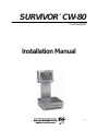
SURVIVOR CW-80
Checkweigher
Installation Manual
32291
Contents
1. Introduction ............................................................................................................. 1-1
About the Manual ............................................................................................................ 1-1
Overview .......................................................................................................................... 1-1
Features .......................................................................................................................... 1-2
Learning the Keypad and LED Displays ........................................................................... 1-3
Keypad Functions and Related Displays ..................................................................... 1-4
Front Panel Annunciator Lights ................................................................................... 1-6
2. Installation ............................................................................................................... 2-1
Unpacking and Assembly ................................................................................................ 2-1
Leveling ........................................................................................................................... 2-2
Making Power Connections ............................................................................................. 2-2
Load Cell Wiring .............................................................................................................. 2-2
Wiring Standard Serial Communications Ports ................................................................. 2-3
Using Optional RS-485 Network Communications ........................................................... 2-4
Wiring the Optional Digital Outputs .................................................................................. 2-6
Optional Battery Backup Operation .................................................................................. 2-7
Board Diagrams ............................................................................................................... 2-8
Power-Up Sequence........................................................................................................ 2-9
3. Configuration ........................................................................................................... 3-1
Before You Begin ............................................................................................................. 3-1
Moving Around in the Menus ........................................................................................... 3-2
SETUP Menu chart .......................................................................................................... 3-4
Menu Descriptions ........................................................................................................... 3-6
4. Calibration ............................................................................................................... 4-1
Overview .......................................................................................................................... 4-1
Calibration Procedure ...................................................................................................... 4-1
5. Operating Modes ..................................................................................................... 5-1
Before You Begin ............................................................................................................. 5-1
Overview of Operating Modes .......................................................................................... 5-2
TARGET Mode ................................................................................................................. 5-3
OU PTT Mode ................................................................................................................. 5-3
Technical training seminars are available through Rice Lake Weighing Systems.
Course descriptions and dates can be viewed at www.rlws.com or obtained by
calling 715-234-9171 and asking for the training department.
© 2004 Rice Lake Weighing Systems. All rights reserved. Printed in the United States of America.
Specifications subject to change without notice.
Version 1.3, January 2004
OU SET Mode ................................................................................................................. 5-4
PTT/SET Mode ................................................................................................................ 5-4
Displaying and Setting Over and Under Tolerance Values ................................................. 5-5
Alternate Method for Changing Over or Under Values ................................................. 5-7
Setting Tare Values........................................................................................................... 5-8
To Display the Current Tare Value ................................................................................ 5-8
Using ID Storage Registers ............................................................................................ 5-12
Keyed ID Selection .................................................................................................. 5-12
Zeroing the Scale ........................................................................................................... 5-14
Test Mode ...................................................................................................................... 5-14
6. Using the EDP Port ................................................................................................... 6-1
Overview .......................................................................................................................... 6-1
Simple Commands (No Response) .................................................................................. 6-2
Inquiry Commands (Requesting Status/Data) ................................................................... 6-5
ID Reference Commands ............................................................................................... 6-15
Commands to Read and Write to IDs............................................................................. 6-20
7. Advanced Features .................................................................................................. 7-1
Bar Graph ........................................................................................................................ 7-1
Red Segments (2) ....................................................................................................... 7-1
Green Segment (1) ..................................................................................................... 7-2
Amber Segments (2) ................................................................................................... 7-2
Setting Bar Graph Segments ...................................................................................... 7-2
Print Formats ................................................................................................................... 7-3
8. Maintenance and Troubleshooting .......................................................................... 8-1
Display Error Codes ......................................................................................................... 8-1
Troubleshooting Table ...................................................................................................... 8-2
Main Board/Display Replacement .................................................................................... 8-3
Removal ..................................................................................................................... 8-3
Installation .................................................................................................................. 8-4
Load Cell Replacement .................................................................................................... 8-5
9. Appendix .................................................................................................................. 9-1
Specifications .................................................................................................................. 9-1
Assembly Drawings ......................................................................................................... 9-4
Replacement Parts List .................................................................................................... 9-6
Indicator and Column Assemblies .................................................................................... 9-6
10" x 10" Base Assembly ........................................................................................... 9-8
12" x 12" Base Assembly ........................................................................................... 9-8
18" x 18", 18" x 24", 24" x 24" Base Assemblies ...................................................... 9-10
ASCII Character Chart ................................................................................................... 9-12
Software Revision History .............................................................................................. 9-13
CW-80 Limited Warranty ................................................................................................ 9-14
ii
1.
Introduction
About the Manual
In this section:
This manual is intended for use by qualified service technicians only. It is
organized to efficiently provide information for installing and setting up the
CW-80 Checkweigher for operation.
■ About the Manual
■ Overview
The Introduction section gives an overview of the CW-80 and its standard
and optional features, explaining the keypad and LED functions.
■ Features
■ Learning the keypad
and LED Displays
Assembly and installation help are found in Section 2.
Section 3 explains how to move through the menus and make selections
while in the Configuration mode. A set up menu page is followed by
detailed descriptions of each set up parameter.
! Warning
Calibration is covered in Section 4.
Some procedures described in this
manual require work inside the
indicator enclosure. These
procedures are to be performed by
qualified field service personnel
only.
Section 5 details the various operational features. The CW-80 offers a
choice of four different operating modes, including an all-new “target”
mode. Read this section and consult with the end-user before configuring the
operating mode of the CW-80.
Sections 6 and 7 cover advanced features like remote operation from an
external keyboard and specialized print formats.
Maintenance, troubleshooting, and replacement parts information appears in
sections 8 and 9.
! Caution
This unit uses double pole/neutral
fusing which could create an
electric shock hazard. Refer
servicing to qualified field service
personnel.
When installation is complete, this manual should be retained by the
installing scale technician. A separate Supervisor’s Operating Guide and
CW-80 Operator’s Card are provided with the unit. They are designed to be
left on-location to assist the scale operator.
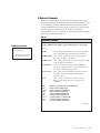
Overview
– –
The CW-80 Checkweigher is a high-speed digital weight indicator and scale
base programmed to compare weight readings with predetermined tolerance
limits defining an ACCEPT band.
+ +
ACCEPT
Red
Green
– – –
–
Amber
+ +
+
✔
Note:
Application specialists at
Rice Lake Weighing Systems are
available to help with unique
situations not covered in this
manual.
+
If the current weight reading is within the acceptable range, the green
“ACCEPT” LED lights. If the current weight reading is less than the
acceptable range, one or more of the red “UNDER” arrowheads light. If the
current weight reading is greater than the acceptable range, one or more of
the amber “OVER” arrowheads light.
In addition to illuminating the appropriate LED’s, the CW-80 can signal the
current Over/Under/Accept status as setpoints by using TTL compatible
digital outputs. A serial port can be used to send out check-weight results to
an external controller or data collector.
300 Over/Under/Tare/Units register sets can be linked to ID’s for easy recall
of stored values. These registers can be modified by serial commands from a
computer, or by using the keys on the front panel.
Introduction
1-1
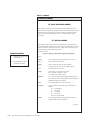
Features
The CW-80 offers a variety of standard and optional features that are shown
below in Table 1-1 and 1-2.
Table 1-1. Standard Features
All standard models include…
• Choice of operating voltage and battery backup:
• 115 VAC operation
• 230 VAC operation
• 115 VAC operation with 6 VDC battery backup
• 230 VAC operation with 6 VDC battery backup
• Large .8-inch, 7-segment, 6-digit LED display
• 8-key membrane touch-panel (keypad) with keys for Over, Under, Tare,
Zero, Units, Print, Target, and ID
• Annunciator lights for unit selection
• High-intensity LED indicators for Over, Under, and Accept
• Display units in decimal lb, kg, oz, lb and oz, grams
• Stainless steel load cell for capacities of up to 60 lb
• Aluminum load cell for capacities of 100 lb and over
• Front panel calibration with internal memory to store calibration constants
• Storage for up to 300 tare and tolerance ID settings
Note:
Some setup parameters may
relate to optional features that
may not be installed on your
CW-80. Changing the parameters for an uninstalled option
has no effect.
• Automatic zero-tracking
• Bidirectional RS-232 or simplex 20 mA current loop communications
• NEMA 4X/IP66 indicator enclosure
Table 1-2. Optional Features
Optional features include...
Electronics:
• 6 VDC replacement battery pack
Note:
Application specialists at
Rice Lake Weighing Systems are
available to help with unique
situations not covered in this
manual.
Outputs:
• 3 TTL active low outputs
• 3 normally-open relays
• 3 normally-closed relay outputs
Software:
• RS-485 communications, 2-wire, half-duplex format
Hardware:
• 24-inch indicator column
• 30-inch indicator column
• 10-inch x 10-inch cutting board
• 12-inch x 12-inch cutting board
• Combination desk/wall mount bracket
• 304 stainless steel clamshell load cell protection for capacities of 100 lb
and over
1-2
CW-80 Checkweigher Installation/Service Manual
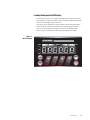
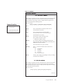
Learning the Keypad and LED Displays
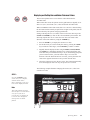
The front panel consists of a 6-digit LED alphanumeric display, individual
status indicators, annunciator LED’s, and a membrane touch-panel (keypad)
encased in a watertight stainless steel case.
Take some time to familiarize yourself with the CW-80 front panel shown
below and the key functions described on the following pages. Table 1-3
provides you with detailed descriptions of all keys and related displays.
Table 1-4 provides information about front panel annunciator LEDs.
Figure 1-1.
CW-80 front panel
CW-80
ACCEPT
UNDER
OVER
kg
NET Net
g
ZERO
MOTION
lb
NEG
oz
TARGET
OVER
UNDER
UNITS
ZERO
UNITS
T
PRINT
TA R E
ID
Introduction
1-3
Keypad Functions and Related Displays
Table 1-3 describes CW-80 front panel keys and related display
functions.
Table 1-3. Front Panel Keys
ZERO key
The ZERO key sets the current Gross weight to Zero, provided the
amount of weight to be removed or added is within the specified Zero
Range and scale is not in motion. The Zero Band can be either 100% or
2% of full scale capacity. This key has secondary functions when using
ID storage and when setting TARE/OVER/UNDER values.
ZERO
UNITS key
The UNITS key switches the weight display to an alternate unit. The
alternate unit is defined in the Setup menu, and could be kg, g, lb, oz, or
lb and oz. Conversions of the weight reading, the Tare value, the Over
value and the Under value occur when the unit of measure is changed
with the UNITS key. This key has secondary functions when using ID
storage and when setting TARE/OVER/UNDER values.
UNITS
UNITS
PRINT key
When enabled, the PRINT key sends “on-demand” serial information
out the serial port provided the conditions for standstill are met. The
Print Out parameter defines the format for printed information. This key
has secondary functions when using ID storage and when setting TARE/
OVER/UNDER values.
PRINT
TARE key
T
TA R E
The TARE key performs one of several predetermined Tare functions
dependent on the mode of operation selected. Setup options include the
following list below. (See TARE description in section 3 for more
information). This key has secondary functions when using ID storage
and when setting TARE/OVER/UNDER values.
In SET Mode
Allows direct tare value entry via front keypad, incrementing or
decrementing as directed until the desired Tare value is displayed. The
last Tare value displayed is stored after 3 seconds of inactivity.
In PTT (push to tare) Mode
Acquires Tare value by pressing TARE key. Positive gross weight on
platter at the time TARE key is pressed is acquired. The display shifts to
the Net mode, NET LED is illuminated, and a NET weight of 0 in the
current unit of measure is displayed. Pressing the TARE key at Gross
Zero removes the tare from the system in this mode.
DIS (disabled)
Disables the Tare function. The NET weight display mode is disabled.
Entry of Tare values is not permitted. Weighing is by gross weight only.
1-4
CW-80 Checkweigher Installation/Service Manual
Table 1-3. (continued)
OVER key/UP ARROW key
OVER
Note:
See the Over bar graph LEDs on
the front panel (Figure 1-1).
OVER key
The OVER key allows the display of the current “Over tolerance” value,
or allows setting the Over tolerance” value. See “Displaying/Setting
Over/Under/Tare Values”. As a secondary function, the OVER key also
acts as an Up Arrow key while in the Configuration mode.
UP ARROW key
When in the SET mode, or when selecting an ID number, pressing this
key establishes an upward direction for modifying the value. When in
the Configuration mode, the Up Arrow key moves “up” one level in the
Configuration menu tree, locking in the value displayed.
UNDER key/DOWN ARROW key
UNDER key
The UNDER key allows the display of the current “Under tolerance”
value, or allows setting the current “Under tolerance” value. As a
secondary function, the UNDER key will also act as an Down Arrow
key while in the Configuration mode.
UNDER
Note:
See the Under bar graph LEDs
on the front panel (Figure 1-1).
DOWN ARROW key
When in the SET mode, or when selecting an ID number, pressing this
key establishes a downward direction for modifying the value. When in
the Configuration mode, the Down Arrow key moves “down” one level
in the Configuration menu tree, allowing you to view a current parameter setting.
TARGET key
When the CW-80 is set up in Target mode, the TARGET key is used to
acquire a weight value from the platter, and assign it as the desired
“Target” value. The CW-80 then computes the Under and Over values
based on predetermined tolerance settings defined during configuration.
TARGET
Note:
See the Accept bar graph LED
on the front panel (Figure 1-1).
LEFT ARROW key
As a secondary function, the TARGET key also acts as a Left Arrow
key when navigating through the Configuration menu tree. When used in
the Configuration mode, the TARGET key moves “to the left” one
position within the Configuration menu tree, allowing you to view other
parameter choices on the same level.
ID key
ID
The ID key is used to select a particular Over/Under/Tare/Units register
set to be retrieved, altered, saved, used, etc.
RIGHT ARROW key
As a secondary function, the ID key also acts as Right Arrow key when
navigating through the Configuration menu tree. When used in the
Configuration mode, the ID key moves “to the right” one position within
the Configuration menu tree, allowing you to view other parameter
choices on the same level.
Introduction
1-5
Front Panel Annunciator Lights
Table 1-4 describes the functions of the front panel annunciator LEDs.
Table 1-4. Front Annunciator LEDs
NET, ZERO, MOTION, NEG
NET Net
NET LED
When illuminated, this LED indicates that the displayed weight is the
NET Weight, or that the CW-80 is in the NET weight display mode, and
that a Tare value is being applied to the current Gross weight reading.
ZERO
MOTION
ZERO (Center of Zero) LED
When illuminated, while in the Gross weight display mode, this LED
indicates that the current displayed weight reading is within +/- 0.25
display division (dd) of the acquired Zero, or is within the Center of
Zero Band. When in the Net weight display mode, it indicates that the
current Net weight reading is within +/- 0.25 dd of the Center of Net
Zero. A display division (dd) is the resolution of the displayed weight
value, or the smallest incremental increase or decrease that can be
displayed or printed.
NEG
MOTION LED
When illuminated, this LED indicates that the scale’s weight reading is
unsettled, or unstable. For the MOTION LED to remain in the OFF
state, scale motion must not have occurred within the last second. A
scale is “In Motion” when the current weight reading varies from the
previous weight reading by more than the value of the Motion Band
(STABLE).
NEG (Minus) LED
When illuminated, this LED indicates that the six displayed digits
represent a negative value when UNITS is set to “lb/oz” mode. It allows
the full 6-digit display to be used for weight display, eliminating the
need to display the minus sign. Normally, a minus sign is displayed on
the 6-digit display.
kg, g, lb, oz
kg
g
lb
oz
lb LED
When illuminated, this LED indicates the unit of measure is pounds (lb).
This setting affects the serial data output unit of measure.
kg LED
When illuminated, this LED indicates the unit of measure is “kilograms”
(kg). This setting affects the serial data output unit of measure.
oz LED
When illuminated, this LED indicates the unit of measure is “ounces”
(oz). This setting affects the serial data output unit of measure.
g LED
When illuminated, this LED indicates the unit of measure is “grams” (g).
This setting affects the serial data output unit of measure.
lb/oz LED
When both the “lb” and “oz” LEDs are illuminated, these LEDs indicate
that the unit of measure is pounds and ounces (lb oz). This setting affects
the serial data output unit of measure as well as the display.
1-6
CW-80 Checkweigher Installation/Service Manual
Table 1-4. (continued)
Bar Graph LEDs: Red, Green, and Amber
UNDER
OVER
ACCEPT
1
2
3
Red Segments (2 of these)
Indicates an underweight condition. When lit, the red segment(s)
indicates that the container weighs less than the lowest acceptable value.
There are three levels of Under weight readings. The leftmost red
segment is used to indicate that the container weight is far below the
acceptable weight band (greatly under); the rightmost red segment is
used to indicate that the container weight is almost in the acceptable
weight band, but still under (slightly under). Illuminating both red
segments indicates “middle ground”, or moderately under.
Bar Graph Segment Key
1 .. Red Segments
2 .. Green Segment
3 .. Amber Segments
––
++
ACCEPT
–––
+++
–
The Bar Graph LEDs provide you with a fast way of determining if a
container is too heavy (Over), too light (Under), or is within an acceptable weight range (ACCEPT). It consists of 5 LEDs (or segments):
+
✔
Bar Graph LED Key
- - - .... greatly under when this one is lit
- - ...... moderately under when both are lit
- ........ slightly under when this one is lit
......... (target) acceptable weight when lit
✔
+ ....... slightly over when this one is lit
+ + ..... moderately over when both are lit
+ + + .. greatly over when this one is lit
Green Segment (1 of these)
Indicates an Accept value. When lit, the green segment light indicates
that the container weight is within the actual acceptable band of weight
limits.
Amber Segments (2 of these)
Indicates an overweight value. When lit, the amber segment(s) indicate
that the container weight is more than the highest acceptable weight
value. There are three levels of Over weight readings. The leftmost
amber segment is used to indicate that the container weight is almost in
the acceptable weight band, but still over (slightly over ); the rightmost
amber segment is used to indicate that the container weight is far above
the acceptable weight band (greatly over). Illuminating both amber
segments indicates a “middle ground”, or moderately over.
See Section 7, Advanced Features, for more information about the Bar
Graph feature.
Introduction
1-7
2.
Installation
Unpacking and Assembly
In this section:
■ Unpacking and Assembly
■ Leveling
■ Making Power Connections
■ Load Cell Wiring
■ Wiring Standard Serial Port
■ Optional RS-485 Network
Communications
1. When opening the shipping carton, notice that the indicator head and
support column or stand are shipped detached from the scale platform.
2. Remove all assemblies from the shipping carton. Notice that the head and
scale platform are joined by a load cell cable. This cable is correctly
wired to the load cell terminal in the indicator head. Do not to pull with
excessive force on the connections at either end of this cable.
3. If mounting the head onto a column, remove the platter from the scale
platform and set aside.
■ Wiring Optional Digital
Outputs
4. Invert the platform so you have access to the column mounting bolts on
the rear and bottom of the platform. Remove the four bolts.
■ Optional Backup Battery
Operation
5. Position the column over the platform mounting holes. Install the four
bolts and tighten them snugly. Install the two feet provided in the hardware kit onto the column.
■ Board Diagrams
6. Turn the CW-80 Checkweigher upright and replace the platter on the
platform.
■ Power-Up Sequence
7. Attach the head to the column with the two bolts provided in the hardware
kit.
! Caution
Do not pick up the scale by the
“spider” assembly which
supports the platter. Lifting by
the spider may damage the load
cell. Lift the scale from under
the base to move it.
If mounting the indicator head to the table/wall stand, simply attach the
head with the two bolts provided in the hardware kit.
! Caution
If rear panel is removed, align
rear panel gasket holes
carefully to prevent driving a
screw through the gasket and
causing a leak. Tighten screws
to 15 in/lbs in alternating
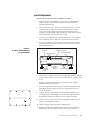
pattern shown below.
9
2
8
4
6
5
Back-panel screw tightening sequence.
Torque screws to final value of 15 in/lbs.
7
3
1
10
Figure 2-1 Mounting column to scale platform
Installation
2-1
Leveling
Select a location for the CW-80 that is reasonably level and free of unnecessary vibrations and air currents.
Adjust the four corner feet on the base until the bubble level on the inside
frame of the unit reads level. When level, the base should not rock and all
four feet should have solid contact with the support surface. If using a
column with your scale, adjust the two column feet until they make solid
contact with the support surface.
Making Power Connections
Static electricity may cause loss
of stored information if the
Checkweigher chassis is not
properly grounded.
The power source used for AC models of the CW-80 must be properly
grounded to an acceptable earth ground. When the indicator head is remotely mounted, the platform must be separately grounded from the chassis
ground screw located on the bottom of the platform. Connect this screw with
18 gauge wire to the same earth ground system as the AC power source.
Failure to ground the base may cause static buildup and incorrect weights.
Note: Because the CW-80 has no power on/off switch, the supply cord
serves as the power disconnect. The power outlet used must be located close
enough to the CW-80 so the operator can easily unplug the unit from power.
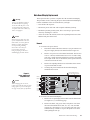
Load Cell Wiring
On all units, the load cell has been wired to the indicator’s CPU load cell
terminal at the factory. On units supplied with a column, extra load cell
cable is coiled inside the indicator head.
If a base and indicator head for remote mounting have been ordered, coil the
extra load cell cable inside the head after installation is complete.
+
D4
R13
D6
R14
R5
D5
F2
R4
R12
Note:
DC
F2
Figure 2-2
Load Cell
Terminal
C4 C5
U1
JU6
R16
R15
JU7
VR1
F3
R7
2-2
U5
C12
C3
JU5
+
C8
AC-1
C13
U3
D3
JU15
+
F5
+
+
3
JU11
AC-2
C2
R2
C10
D1
D2
C9
JU10
R10 R11
1
C1
2
JU9
R8 R9
R1
F4
GND-3
C11
U4
JU12
JU4
-
J2
R3
CR1
T1
F6
JU13
S/N
P/N
-EX
A
-SE
-SI
REV
+SI
+SE
+EX
B
SHI
T+
GND
RxD
TxD
B
A
C
-EX
-SE
-SI
+SI
+SE
+EX
SHI
-EX
-SI
+SI
+SE
+EX
SHI
Remove both
jumpers if using
6-wire load cells
with sense lines.
-SE
+EXC
-EXC
+SIG
-SIG
+SENSE
-SENSE
SHLD
U2
JU8
Aluminum load cells in scales
with capacities from 100-1000 lb
use the following wiring code:
Green
Black
Red
White
Blue
Brown
bare
C7
C6
JU14
R6
F1
J3
Stainless steel load cells in scales
with capacities from 6-60 lbs use
the following wiring code:
Green +EXC
Black
-EXC
Red
-SIG
White
+SIG
Yellow SHLD
CW-80 Checkweigher Installation/Service Manual
You can access all
terminal blocks on the
CPU Board and Power
Board by removing the
rear cover of the indicator
case. The cover is held on
by 10 screws.
D
If using 6-wire load cell
cabling, remove the two
jumpers above the load
cell terminal strip.
Wiring Standard Serial Communications Ports
Serial communications for the CW-80 is provided through a serial
communications terminal block located on the CPU board next to the
load cell terminal block. (See Figure 2-3).
Note:
The four cord grips on the bottom
of the indicator head should be
used for the cables listed below.
Refer to Figure 2-3.
B — Load Cell Cable
This terminal block provides a port for both EDP (Electronic Data
Processing) devices and printers or remote displays. You must configure
this port for your specific application (see Section 3, Configuration, for
more information). The CW-80 communicates with bidirectional RS232C and/or output-only 20 mA Current Loop interfaces. For network
applications with up to 32 devices, 2-wire, half duplex RS-485 is
available as an option.
C — Serial Communications Cable
See Table 2-1 for serial terminal block wiring configurations.
A — Backup Battery Cable
D — AC Power Cable
Table 2-1.
Serial Communications Port
Pin
EDP
(RS-232)
Bidirectional
EDP
(20 mA)
Out Only
Network
(RS-485)*
Half Duplex Bidirectional
—
GND
RXD
TXD
—
—
T+
GND
—
—
—
—
—
GND
—
—
485B
485A
T+
GND
RXD
TXD
B
A
* Optional feature: See Section 7, Advanced Features, for more information.
+
D4
D5
R14
R13
D6
R12
F2
R4
DC
F2
Figure 2-3.
Serial communication
terminal
C4 C5
R5
U1
JU6
R16
R15
JU7
VR1
F3
R7
C6
C7
U2
U5
C12
JU14
R6
F1
J3
JU8
C3
JU5
+
AC-1
D3
JU15
+
C10
AC-2
C2
R2
R10 R11
D1
C13
U3
JU10
F5
+
+
3
JU11
1
C1
D2
C9
2
C8
R1
F4
JU9
R8 R9
GND-3
C11
U4
JU12
JU4
-
J2
R3
CR1
T1
F6
JU13
S/N
P/N
-EX
A
-SE
-SI
REV
+SI
+SE
+EX
B
SHI
T+
GND
RxD
C
TxD
B
A
D
Rev.
GND
RxD
TxD
B
A
T+
GND
RxD
TxD
B
A
T+
Installation
2-3
The following communications parameters (Table 2-2) apply to both the
RS-232 and 20mA Current Loop interfaces.
Table 2-2.
Serial communications parameters
• Continuous or Demand outputs
• 150, 300, 600, 1200, 2400, 4800, 9600, or 19200 baud rate
• 7 data bits (with parity) or 8 data bits (no parity); 1 start bit and 1 stop
bit
• None, odd, or even parity
• Line termination: <CR LF> or <CR>
• End of line delay up to 2.0 seconds in 200 mS increments
Using Optional RS-485 Network Communications
Note:
RS-485 must be purchased at time of
order and factory installed. No field
installation of this option is available.
You can configure multiple CW-80 Checkweigher to operate on a
2-wire RS-485 network serial communications line. The expanded
serial communication option allows network applications.
To enable RS-485 communications, you must connect two communication wires to terminals A and B on the serial communications terminal.
A ground wire is also required. See Figure 2-3 and Table 2-1 on the
previous page for more information on expanded serial communications.
Consider the following guidelines for an RS-485 interface.
Table 2-3.
RS-485 hardware
• Every piece of equipment must have a unique address.
• Every piece of equipment must remain quiet while waiting for a
command.
• All interface wiring and RS-485 transceivers must be correctly installed
as 2-wire implementations.
• The ground terminals of all equipment in the network must be connected
to minimize common mode voltage differences.
Table 2-4.
RS-485 software
• The controller software must be compatible with the CW-80’s protocol.
Some equipment may have its own, proprietary RS-485 protocol.
• All equipment in the RS-485 network must follow the rules of half
duplex communications: “Be quiet unless spoken to” and “Never echo
back what you are receiving.”
• The controller must turn on its transmitter, send the commands, wait for
the transmission, and finally, turn off its transmitter to listen.
• The controller software must be able to handle the echo from its own
transmission, since the transmit and receive lines are shared.
2-4
CW-80 Checkweigher Installation/Service Manual
You enable the optional RS-485 software protocol for the CW-80 by
assigning an address to the EDP port in the Serial menu. The address
assigned must be a 2-digit integer between 00 and 99.
Since the RS-485 protocol requires that each device has a unique
address, all remote commands sent to a checkweigher must be initiated
as shown below:
<SOH> <ADDRESS> <COMMAND> <CR>
ASCII 01
decimal
character
EDP serial command
2-digit address (00-99) of the
receiving CW-80
ASCII carriage return character
Optionally, a <CR> <LF> may be
sent
If the address of the incoming command matches the port address of a
CW-80 listening on the RS-485 network, that CW-80 responds.
For demand outputs, the protocol is as shown below:
<STX> <RESPONSE> <CR>
ASCII 02
decimal
Response
commands from
CW-80
ASCII 13 decimal
character, or
<CR> <LF>
13
10
For example, suppose you wish to send a remote command from an
ASCII terminal to call up the current target value of ID# 005 of a
particular CW-80 on the RS-485 network. After checking the appropriate command reference table, you determine that XTG is the correct
command to use. Assume the CW-80’s address is 65.
After consulting an ASCII chart, you determine that the keyboard
equivalent for the SOH character (02) is CONTROL-A, and the CR
character is ENTER. Therefore, from the terminal you press:
<CONTROL-A>,6,5,X,T,G,0,0,5,ENTER.
The CW-80 responds with:
<STX>G005
2.50KG<EOL>
If the CW-80 is configured for continuous outputs, the protocol will be
dependent upon the print format selected. See Section 7-3 through 7-6
for more information on selecting print formats.
Installation
2-5
Wiring the Optional Digital Outputs
TTL Output Options
Wire selected digital outputs for Over, Accept, and Under to connector J2
on the power supply board (Figure 2-4). There is capacity for up to 3 TTL
outputs. Table 2-5 provides J2 pin numbers and corresponding digital
connections.
NOTE:
Unless one of the Output
Options (B–G) has been
ordered, no terminal block (J2)
or other relay components are
included on the CW-80 board
for wiring digital outputs.
Each output is an open-collector circuit, capable of sinking 250 mA when
“on” and withstanding +40 VDC when “off.” All logic levels are activelow. The circuits include +5 V pull-up resistors to drive TTL or 5 V
CMOS logic without additional hardware.
Wiring for optional relays uses
the same J2 terminal block as
the TTL digital output option.
Additionally, if a relay option
has been ordered (Options C, D,
F, of G) selected wire traces
have been cut at the factory to
enable relay use.
Relay Output Options
If equipment is to be driven that requires more than 5 V TTL levels,
optional plug-in relays are available for relays sockets on the CW-80
power supply board. These on-board relays are necessarily small—rated
for a maximum 0.5 Amp, 100 VDC. Maximum power draw is 10 Watts.
Note that because each relay
has its own separate set of dry
contacts, it is possible to have
both AC and DC relays on the
same terminal block.
If equipment is to be driven requiring higher current draw, use the externally-mounted Opto 22 4-channel relay rack (PN 15973) with plug-in relay
modules. These relays are rated up to 3 Amps and are available in a variety
of AC or DC voltages in both normally-open and normally-closed models.
To operate equipment larger than 3-Amp draw, larger isolation relays may
be externally-mounted and used in series with the on-board relays.
Table 2-5.
J2 – digital output connections
Figure 2-4.
Digital output connector J2 on
power supply board
J2 Pin
Signal
NO Relay
NC Relay
1
2
Ground for Over
Over
Closes for Over
Opens for Over
3
4
Ground for Accept
Accept
Closes for Accept
Opens for Accept
5
6
Ground for Under
Under
Closes for Under
Opens for Under
7
8
Not used
Not used
➤
Nomex insulative strip over
AC voltage selection jumpers
Battery Battery +
J3
Gnd
Over
2
Gnd
3
Accept
4
Gnd
Under
5
not used
not used
7
8
1
J2
2-6
CW-80 Checkweigher Installation/Service Manual
Optional Relay
Sockets
SPITZNAGEL
6
AC-1
AC-2
GND
J1
Optional Battery Backup Operation
! Warning
The optional DC battery is a
lead/acid model which gives off
flammable gases when charging.
A vent hole in the bottom of the
battery case allows these gases
to escape. Do not obstruct the
vent hole.
NOTE: The CW-80 is not UL
listed for operation with the
battery backup power supply.
A DC battery backup power supply is available on special order for factorymounting in the checkweigher column. If AC power fails, this battery
provides backup power until AC power resumes. The battery is for emergency use only, and is not designed to be the main power source used each
day.
Whenever AC power to the checkweigher is ON, the battery receives a lowamperage charge to maintain its capacity. If completely discharged, the
battery can be recharged in 36 hours by this method. For rapid charging in
8-12 hours, a separate AC recharging unit is available. Quick connectors
allow easy disconnection of the indicator power cable and connecting the
battery charger in its place. See Figure 2-5.
Figure 2-5.
Backup battery and
separate charger
6
-VDC 1
+VDC 2
5
4
3
2
1
Figure 2-5 Key
1 .... Battery Case and Mounting Plate
2 .... 6 V Battery
3. ... Battery Quick Connector
4 .... Power Cable and Charger Quick Connectors
5 .... Power Cable to Indicator (blue -, brown +)
6 .... 115 VAC to 6 VDC Battery Charger
Installation
2-7
Board Diagrams
Nomex insulative strip over
AC voltage selection jumpers
➤
Figure 2-6.
Power supply board
(component side)
Battery Battery +
J3
Gnd
Over
2
Gnd
3
Accept
4
Gnd
Under
5
not used
not used
7
8
1
Optional Relay
Sockets
AC-1
SPITZNAGEL
6
AC-2
GND
J2
J1
6
Figure 2-7.
CPU board
(component side)
-EX
-SE -SI
+SI
2
+SE +EX SHI
T+ GND RxD TxD
7
3
Figure 2-7 Key
1 .... Ribbon Cable to Keypad
2 .... Load Cell Terminal
3. ... Serial Communication Terminal
4 .... Configuration (Setup) Push Switch
5 .... Ribbon Cable to Power Supply Board
6 .... Ribbon Cable to Display Board
CW-80 Checkweigher Installation/Service Manual
A
4
5
1
2-8
B
Power-Up Sequence
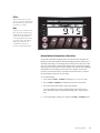
When the CW-80 is powered-up, the following displays appear in sequence:
1. DISPLAY TEST — All LED’s and number segments light.
2. SOFTWARE VERSION — Software revision number is displayed.
3. INITIALIZATION — “Init” is displayed.
NOTE:
After powering up the indicator,
allow the unit to warm up at
least 10 minutes before using in
a legal-for-trade application.
4. 0.0 — Scale zeros weight allowable in Auto Zero Range setting (if calibrated and
in weighing mode),
or
NO CAL — “No calibration” message appears (if scale is not calibrated),
or
SETUP — “Setup” message appears (if scale is in Setup mode).
Installation
2-9
3.
Configuration
Before You Begin
In this section:
■ Before You Begin
■ Moving Around the Menus
■ Setup Menu Chart
■ Setup Menu Descriptions
■ Serial Menu Chart
■ Serial Menu Descriptions
■ Calibration Menu Chart
■ Calibration Menu
Descriptions
The CW-80 Checkweigher has a push-switch on its main board to switch
between the Configuration mode and Normal Operating mode. The switch is
accessible through a hole in the rear panel normally closed off by a drilledhead fillister screw and water-tight washer (Fig. 3-1, #1). Removing the
screw lets you operate the switch without opening the case.
To set up and calibrate the CW-80, you must be in the Configuration mode.
Remove the fillister screw and washer (#1) over the set-up switch. To enter
the Configuration mode, insert a small diameter object like a screwdriver or
pen through the access hole until it touches the setup switch. Gently press
the switch until the word “SETUP” is displayed on the front panel.
Once configuration and calibration are completed, press the switch again to
return to Normal Operating mode. Access to the switch can be denied by
threading a wire through fillister screws (1) and (2) shown in Fig. 3-1 below,
then connecting the ends of the wire into a loop with an official regulatory
seal.
Figure 3-1.
Set-up switch
behind rear panel
1
2
Established digital outputs
may still be activated when
changing parameters or
calibrating. De-energize any
external equipment controlled by the indicator’s
digital outputs while such
changes are being made.
Figure 3-1 Key
1 .. Fillister screw over set-up switch
2 .. Fillister screw for sealing case
Configuration
3-1
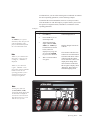
Navigational keys
Moving Around in the Menus
After setting the mode switch to the Configuration mode, you have access to
three menu choices that allow you to setup and calibrate the CW-80. The
Configuration menus are: SETUP, SERIAL, and CALIB. A fourth menu
item, TEST, is used only for factory diagnostic purposes.
OVER
UP Arrow Key:
Moves up to previous level.
UNDER
DOWN Arrow Key:
Moves down to next level.
TARGET
LEFT Arrow Key:
Moves left on same level.
A fifth key, ZERO is used to lock in numerical entries.
RIGHT Arrow Key:
Moves right on same level.
Once the menu item to be modified is selected , you use the UNDER key to
“drop down” to the next level to view all the possible parameter settings for
that menu item. Use the TARGET or ID keys to scroll through all possible
selections for that menu level.
ID
ZERO
ZERO Key:
Locks in numeric values.
To set up the CW-80, you navigate through the configuration menus with
four front-panel keys that become directional keys while in the Configuration mode. Navigational keys are shown at left.
For example, if you select Z BAND (Zero Band) at this level, use the
UNDER key to move down one level to view all the possible parameters. If
you wish to select 2 PC (2%) as the parameter, use the TARGET or ID keys
to scroll to 2 PC. When 2 PC is displayed, use the OVER key to lock in 2
PC as the Zero Band setting See Figure 3-2 below.
Figure 3-2.
Example: Setting Zero Band to 2%
TEST
SETUP
STABLE
Z BAND
2 PC
NOTE: When exploring the menu, be
careful not to accidentally change
parameter settings. Remember, the
CW-80 locks in whatever is displayed
when you move up a level; make sure
the desired setting is on the display
before you press OVER key to exit.
3-2
SERIAL
CALIB
Z TRAC
100 PC
Always scroll back up to the first level SETUP menu when you have made
changes in parameter settings. If you return to Normal Operating mode
before scrolling completely up to SETUP, changes may be ignored.
Because the CW-80 automatically acquires Zero upon leaving Configuration
mode, be certain the platter is clear when switching to Normal Operating
mode.
See Figures 3-4 through 3-6 for the structure of the SETUP, SERIAL, and
CALIB (Calibration) menus.
CW-80 Checkweigher Installation/Service Manual
Figure 3-3.
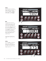
Entering numeric values
CW-80
Note:
Numeric Entry of Values: Some menu
items require a numeric entry. In such a
case, you enter numeric values using the
navigational keys as shown at right.
ACCEPT
UNDER
OVER
kg
NET Net
ZERO
g
MOTION
lb
NEG
oz
TARGET
OVER
When a numeric value is displayed, one
of the digits will be blinking. That digit is
active and can be changed. Press the
OVER or UNDER keys to make the
blinking active digit larger or smaller.
UNDER
UNITS
ZERO
UNITS
T
PRINT
TA R E
ID
CW-80
ACCEPT
UNDER
OVER
kg
NET Net
To change which digit is blinking, press
the TARGET or ID keys.
ZERO
g
MOTION
lb
NEG
oz
TARGET
OVER
UNDER
UNITS
ZERO
UNITS
T
PRINT
TA R E
ID
CW-80
ACCEPT
UNDER
When you have changed the numerical
display to the desired value, press the
ZERO key to lock in that value.
OVER
kg
NET Net
ZERO
g
MOTION
lb
NEG
oz
TARGET
OVER
UNDER
UNITS
ZERO
UNITS
T
PRINT
TA R E
ID
Configuration
3-3
SETUP Menu chart
The following figure provides a graphic representation of the CW-80 Checkweigher Setup menu structure. In the
actual menu structure, the settings you can choose under each parameter are arranged horizontally. To save page space,
menu choices are sometimes shown arranged vertically, with the factory default indicated by a check mark.
Figure 3-4.
Setup menu
XXXXXXX
OFF
2 PC √
OFF √
0.5 dd
FS + 0 dd √
0.5 dd
100 PC
0.5 dd
1.0 dd
FS + 1 dd
1.0 dd√
1.0 dd
2.0 dd
FS + 9 dd
2.0 dd
2.0 dd
3.0 dd√
FS + 2 PC
3.0 dd
3.0 dd
10 dd
5.0 dd
10.0 dd
ON √
ON √
ON √
ON √
ON √
ON √
ON √
ON √
OFF
OFF
OFF
OFF
OFF
OFF
OFF
OFF
Hidden if
ALT 1 is OFF
number
Press ID or Press ZERO
TARGET key key to enter
to select unit.
number
The active
red unit light
indicates the
choice.
kg √
g
lb √
oz
3-4
Default may
be kg or lb,
depending on
shipping
destination
√
888888 √
88888.8
Press ID or
TARGET key
to select unit
8888.88
OFF √
888.888
lb/oz
88.8888
oz
8.88888
lb
Scale’s capacity is
displayed. Place
decimal point
where needed
g
CW-80 Checkweigher Installation/Service Manual
kg
Hidden if
ALT 2 is OFF
Load factor
(LF) is in terms
of % of default
unit grads
Press TARE
key to view
the alternate
resolution load
factor for the
selected unit
√
.040 S√
1√
.120 S
2
.240 S
4
.480 S
8
.720 S
16
1 dd
1.000 S
32
2 dd
1.480 S
64
5 dd√
2.000 S
128
10 dd
√
√
OFF√
2.480 S
20 dd
3.000 S
50 dd
1
2
4
8
16
32
same setting choices as Ptt.SEt
number
(grads)
number
number
(grads)
number
(grads)
number
(grads)
number
(grads)
number
(grads)
number
(grads)
number
(grads)
number
(grads)
number
(grads)
Configuration
3-5
Menu Descriptions
Tables 3-1 through 3-3 provide complete information about each of the main menu options. Each table describes all
parameters associated with that particular menu option, the choices available for each parameter, and a general
description of each parameter and related choices. The system defaults are indicated by a check mark (√).
Table 3-1.
SETUP menu
Menu Item…
Parameter…
Description…
UNITS
DEFALT
ALT-1
Units. Sets up the CW-80 start up or default unit of measure (DEFALT), as well as any
possible alternate units of measure (ALT 1, ALT2, and ALT3).
(ALT2)*
Note that units selection is not indicated by letters on the numeric display, but by the
illuminated Units LED’s to the right of the numeric display. Press ID key or TARGET key
to select the unit.
(ALT3)*
From the DEFALT parameter, you can set up the default unit of measure. Alternate units of
measure can be set up from the parameters ALT1, ALT2, and ALT3. The default unit of
measure establishes the start up, or primary unit and determines the unit by which the scale
will be calibrated. The possible choices are lb, oz, g, and kg. Units selection is indicated by
the illuminated Units LED’s to the right of the numeric display.
When alternate units of measure are desired, you can use the UNITS key to set the weight
display unit under ALT 1, ALT 2, or ALT 3. Note that ALT2 will be hidden unless ALT1 is
active. Likewise, ALT3 will be hidden unless ALT2 is active. Each of the alternate units can
be set up to be any of the possible units: lb/oz, oz, lb, g, and kg.
DEFALT
SEL UN
GRADS
CNT BY
DEC PT
Default. Sets the default unit of measure. DEFALT establishes the primary unit of measure
for the CW-80; it also determines the unit by which the scale will be calibrated.
In addition to the units of measure, you can set the scale graduations, decimal point settings,
and Count By display resolution from the DEFALT menu item.
For the default unit of measure, the possible selections are oz, lb, g, and kg. The lb/oz unit is
not allowed as a start up default unit, as the CW-80 will not calibrate with lb/oz as the
default.
ALT-X
SEL UN
ALT-X. Allows you to set up any of the alternate units of measure. Note that ALT2 is
hidden unless ALT1 is active (not set to OFF), and ALT3 is hidden unless ALT2 is active.
To configure an alternate unit of measure, select the unit from the following list of
parameter options: kg, g, lb, oz, lb/oz, and OFF. The default is OFF.
LF (Load Factor)
Next, select the desired load factor (LF). A load factor is a ratio of the number of
graduations that an ALT-X unit has in relation to the DEFALT unit of measure.
Note:
If alternate units are set up, do not
change any parameters for the
DEFALT unit which would affect
calibration (graduations, count by
display divisions, or decimal point
position). Calibration will be lost and
any settings established for ALT 1,
ALT 2, or ALT 3 units will be lost.
For example, if the CW-80 is configured so that the DEFALT unit of measure will use
2000 grads, then a load factor of (LF 0.90) will result in an alternate unit using 90% of
that number of grads (0.90 x 2000 grads = 1800 grads). Similarly, a LF 1.10 will utilize
2200 grads (1.10 x 2000 grads).
Note: The display shows the standard resolution load factor (LF) for the unit selected.
You can press the TARE key to view an alternate resolution load factor for the unit
selected. Select either the standard or alternate resolution load factor. Choosing a load
factor ≤ 1.00 will result in the same or fewer graduations for the ALT-X unit of measure,
maintaining Legal-For-Trade compatibility.
* These alternate unit selections are visible only if the prior alternate unit has been activated (is not set to OFF).
3-6
CW-80 Checkweigher Installation/Service Manual
(continued)
Table 3-1. (continued)
SETUP menu (continued)
Menu Item…
Parameter…
Description…
SEL UN
OFF √
lb/oz
oz
lb
g
kg
Select Units. Select from the given list of units for DEFALT, ALT1, ALT2, or ALT3.
The SEL UN parameter can be set to oz, lb, g, and kg for the DEFALT unit, while the
SEL UN parameter can be set to OFF, lb/oz, oz, lb, g, and kg for any of the ALT-X
units.
GRADS
number
Note: Units selection is not indicated by letters on the numeric display, but by the
illuminated Units LED’s to the right of the numeric display. Press the ID or TARGET
key to select the desired unit’s red LED.
Displayed Graduations. Specifies the number of full scale graduations for the DEFALT
unit only. Press the ZERO key to enter the desired number.
The graduations are selectable from 1 to 50,000 using the navigational keys. The
default is 3000 graduations. See page 3-3 for the procedure for altering and entering
numeric values into the CW-80.
CNT BY
DEC PT
STABLE
Z BAND
DIV 1 √ DIV 100
DIV 2 DIV 200
DIV 5 DIV 500
DIV 10
DIV 20
DIV 50
Count By Resolution. Selects the count-by resolution (display divisions), and works in
conjunction with the DEC PT parameter.
888888 √
88888.8
8888.88
888.888
88.8888
8.88888
Decimal Point Position. Allows you to place the decimal point position. The CW-80
combines the settings of GRADS and CNT BY to display the default scale capacity
with no decimal point.
OFF
0.5 dd
1.0 dd √
2.0 dd
3.0 dd
5.0 dd
10.0 dd
Stable. Sets the level at which scale motion is detected by comparing the present
display update with the previous update. If motion is detected, the MOTION LED is
turned ON.
2 PC √
100 PC
Zero Band. Selects the range of weight which may be “zeroed” off the scale. This is
done by either pressing the ZERO key or by using automatic Zero Tracking
(Z TRAC). See the Z TRAC menu for a description of the automatic Zero Tracking
function.
Note that choosing a selection with “dummy zeros” (10, 20, 50, 100, 200, or 500) will
result in a condition where the decimal point selection in the DEC PT menu item will
not appear. Instead, a “nO dP” message will be displayed.
Use the Left Arrow or Right Arrow keys to place the decimal point where needed. This
allows you to immediately see the current scale capacity without leaving the Setup
mode to find out how the CW-80 was configured.
A setting of OFF indicates that the motion band is infinitely wide. Therefore, the
MOTION LED will not turn ON. All serial port output indicates “Not in-Motion”
status when transmitted. In addition, print modes, zeroing, and taring that require a
stable scale before transmission will always have this condition satisfied.
Z BAND selections are either ±2% of full scale or 100% of full scale. The reference
point at which the Zero Range is centered is the Start Up Zero acquired at power-up.
(continued)
Configuration
3-7
Table 3-1. (continued)
SETUP menu
Menu Item…
Parameter…
Description…
Z TRAC
OFF √
0.5 dd
1.0 dd
2.0 dd
3.0 dd
Zero Track. Sets the condition for the CW-80 to perform automatic adjustments of the
Acquired Zero. When the condition is satisfied, the adjustments are made simultaneously. The following conditions must be met for Zero Tracking to occur.
• Standstill for more than 1 second
• Current gross weight within Z TRAC grads of center of zero
If satisfied, the CW-80 makes the current weight reading the new Acquired Zero.
The parameter choices indicate how many displayed graduations may be “Zeroed”
OFF the scale. Selecting OFF disables Zero Tracking.
Maintenance of Gross Zero is allowable only up to the limits set by Z BAND (See Z
BAND definition).
THRESH
OFF
0.5 dd
1.0 dd
2.0 dd
3.0 dd √
10.0 dd
Zero Threshold. Allows you to select a threshold or reset point where automatic
printing functions reset themselves to be retriggered. In some cases, it is not practical
to have the CW-80 return to 0 to reset its auto print functions. See PFUNCT for more
information concerning the auto-print modes supported by the CW-80.
O LOAD
FS + 0 dd √
FS + 1 dd
FS + 9 dd
FS + 2 PC
Overload. Indicates where Gross Overload/Underload Blanking of the CW-80 display
should occur due to a scale overload condition. The default settings is Full Scale (FS +
0 dd).
PSHBUT
ID
TARGET
TARE
PRINT
UNITS
ZERO √
UNDER
OVER
Pushbutton. Allows disabling any key’s primary function during normal operating
mode. Secondary function of keys are not affected. Any key can be enabled or disabled
within this menu (either ON or OFF). The default for each individual key is ON.
UPDATE
.040 S √
.120 S
.240 S
.480 S
.720 S
FILTER
1√
2
3
4
8
16
The THRSH parameter is also used to give you a band greater than 0 (where the
UNDER LEDs are OFF and the UNDER digital outputs remain inactive). Retriggering
does not occur until an equivalent weight in excess of the THRESH value is placed on
the CW-80 platter.
The default setting (ZERO) enables all keys.
1.000 S
1.480 S
2.000 S
2.480 S
3.000 S
32
64
128
Display Update Rate. Sets the time desired for updating the display (in seconds). Even
though the A/D acquires new weight information at a faster rate, it may be desirable to
update the display at a slower and more stable rate.
Digital Filter. Sets the amount of mathematical averaging to be applied to the incoming
weight reading. The more vibration in the area, the higher the filtering should be set. A
setting of 1 indicates no filtering, while a setting of 128 indicates the most filtering.
(continued)
3-8
CW-80 Checkweigher Installation/Service Manual
Table 3-1. (continued)
SETUP menu
Menu Item…
DISPLAY
SLEEP
Parameter…
ON√
OFF
ID STR
Display. Defines whether the numeric display will be on, or merely the bar graph. The
default is ON. To disable the numeric display, select OFF.
DELAY LEVEL
OFF√
1
2
4
8
16
32
Description…
1 dd
2 dd
5 dd√
10 dd
20 dd
50 dd
ON √
OFF
R-ONLY
Sleep Mode. Defines when and if the CW-80 should change to a low power state to
conserve power.
DELAY is the number of minutes the CW-80 will remain at full power without seeing
any activity.
The LEVEL parameter sets the amount of weight change the CW-80 must read before
powering back up to full power.
NOTE: Sleep mode must be set to OFF for any legal-for-trade application.
ID Storage. Defines whether multiple nonvolatile Over/Under/Tare/Units storage
registers sets are available, or whether a single set of Over/Under/Tare/Units registers
are used. Choices are ON, OFF, and R-ONLY (read only).
• ON enables multiple Over/Under/Tare/Units storage of ID numbers from 001 to 299
• OFF disables this storage.
• R-ONLY (read only) enables multiple Over/Under/Tare/Units storage, but protects
them from accidental overwrite.
TARE
OFF √
SET
PTT
Tare Function. Allows or disallows keyed or push-button tares. Tares can be entered
either by keypad entry (SET), or by push-button acquisition from weight on the
platter (PTT).
• OFF disables the Tare function. No entry of Tare values is permitted.
• SET enables Tare value entry with front keypad “Up” and “Down” arrow keys,
incrementing or decrementing the number until desired Tare value is displayed.
After a 3-second timeout with no key presses, the Tare value on the display is
stored.
• PTT enables Tare value acquisition by pressing front panel TARE key. Weight on
platter at time of TARE key press is put into the current Tare register.
OPERAT
TARGET√
OU.PTT
OU.SET
PTT.SET
Operate. Allows choosing one of four different operating modes that determines how
the CW-80 will establish the ACCEPT band in Normal Operating mode. The ACCEPT
band falls between the settings for the first Under light (UN 1) and the first Over light
(OV 1). The four modes below are explained in more detail on the following page:
• TARGET: Target mode (installer sets OV 1 and UN 1 band width in Set Up mode)
• OU.PTT: Over/Under Push to Tolerance mode (operator’s keypresses command the
CW-80 to acquire UN 1 and OV 1 from actual weights on platter)
• OU.SET: Over/Under Set mode (operator keys in digital UN 1 and OV 1 values)
• PTT.SET: Push to Tolerance and Over/Under Set mode (combination of PTT and
SET. Values acquired from platter can be modified digitally)
(continued)
Configuration
3-9
Table 3-1. (continued)
SETUP menu
Menu Item…
Parameter…
Description…
UN 1
UN 1-2
UN 2
OV 1
OV 1-2
OV 2
Target mode. Pressing the TARGET key allows the CW-80 to acquire the current weight on
the platter as a Target value. The Target Value is an “ideal weight” or reference value around
which the over (OV 1) and under (UN 1) tolerance values are automatically adjusted during
operation. All weights between UN 1 and OV 1 will be in the ACCEPT range. All UN and
OV values are set in grads (dd) and function as follows:
OPERAT
TARGET
UN 1:
Lower limit of ACCEPT band. Number of grads from Target value until ACCEPT
goes off and first (innermost) Under light comes on.
UN 1-2: Number of grads from UN 1 until both Under lights come on.
UN 2:
Number of grads from UN 1-2 until last (outermost) Under lights comes on.
OV 1
Upper limit of ACCEPT band. Number of grads from Target value until ACCEPT
goes off and first (innermost) Over light comes on.
OV 1-2: Number of grads from UN 1 until both Over lights come on.
OV 2:
Number of grads from UN 1-2 until last (outermost) Under lights comes on.
Target Value
UN 1-2
OV 1-2
ACCEPT
UN 2
UN 1
OV 1
OV 2
OU.SET
UN 1-2
UN 2
OV 1-2
OV 2
Over/Under Set mode. Allows operator to set the ACCEPT band by digitally entering the
Over 1 and Under 1 values. Once the current Over 1 or Under 1 value is displayed, the
operator uses the “Up” and “Down” keys to increment or decrement the displayed value.
Once a 3-second keypad inactivity interval has passed, the CW-80 locks in the current
displayed value as the Over 1 or Under 1 value. Rather than wait for the 3-second timeout,
you can also press TARGET or ID to store the value. The word “STORED” appears on the
display for 1 second. This mode disables the TARGET key.
OU.PTT
UN 1-2
UN 2
OV 1-2
OV 2
Over/Under Push to Tolerance mode. Pressing the OVER or UNDER key instructs the CW80 to acquire the current weight reading as the Over 1 value or Under 1 value. It displays the
word “STORED” and stores the acquired weight reading in the appropriate Over or Under
value register. This mode disables the TARGET key.
UN 1-2
UN 2
OV 1-2
OV 2
Push to Tolerance and Over/Under Set mode. This mode combines features of the OU.Ptt
mode and the OU.SET mode. Over 1 and Under 1 values are first acquired from weight on
the platter, as in the OU.Ptt mode. the operator may then view those values by pressing the
OVER or UNDER keys. Then, by direct keypad manipulation of the keys beneath the
displayed digits, he may adjust the displayed Over/Under value, as in the OU.SET mode.
Once a 3-second keypad inactivity interval has passed, the CW-80 locks in the current
displayed value as the Over 1 or Under 1 value. Rather than wait for the 3-second timeout,
you can also press TARGET or ID to store the value. The word “STORED” appears on the
display for 1 second. This mode disables the TARGET key.
PTT.SET
3-10
CW-80 Checkweigher Installation/Service Manual
Figure 3-5.
Serial menu
XXXXXXX
9600 √
8 NONE √
CR LF √
19200
7 EVEN
CR
150
7 ODD
0 SEC √
.2 SEC
OFF √
number
RS 232
Set address
number with
directional
navigator
keys, then
enter number
with ZERO
key.
.4 SEC
RS 485
300
.6 SEC
600
.8 SEC
1200
1.0 SEC
2400
1.2 SEC
If RS-485
option has
been
purchased
and installed
by factory
4800
1.4 SEC
1.6 SEC
1.8 SEC
2.0 SEC
√
√
ON √
ON
OFF √
OFF
OFF √
ON
Configuration
3-11
Table 3-2.
SERIAL menu
Menu Item…
Parameter…
Description…
BAUD
150
300
600
2400
4800
9600√
Baud Rate. Selects the transmission speed for the serial port.
1200
19200
BITS
8 NONE √
7 EVEN
7 ODD
Bits and Parity. Selects the number of data bits and parity for the serial port.
PORT
OFF √
RS-232
RS-485
Port for EDP Communications. Selects either RS-232 or RS-485 serial communications
protocol. RS-485 appears only if it has been purchased and factory-installed..
EOL
CR √
CR LF
End of Line Characters. Selects how a line of data transmitted through the serial port ends.
It does not indicate which EOL termination to expect with incoming transmissions.
EOL DLY
0 SEC √
.2 SEC
.4 SEC
.6 SEC
.8 SEC
1.0 SEC
1.2 SEC
1.4 SEC
1.6 SEC
1.8 SEC
2.0 SEC
End-of-Line Delay. Sets the delay period (in seconds) from when a formatted line is
terminated to the beginning of the next serial output. This allows the CW-80 to communicate with peripheral equipment with little or no receive buffers.
ADDR
number
Address. Sets the address of the CW-80 for bidirectional serial communications within a
network. Set the address number with the navigational keys, and then enter the number
with the ZERO key. When a nonzero address is assigned, the CW-80 interprets and
executes serial commands intended solely for it. When the address is not 0 but the serial
command is intended for CW-80 00 (broadcast), all CW-80s interpret and execute the
serial commands, but they do not acknowledge receipt of the serial command. The default
setting for ADDR is 00, but 00 should never be selected as the checkweigher’s address.
(continued)
3-12
CW-80 Checkweigher Installation/Service Manual
Table 3-2. (continued)
SERIAL menu
Menu Item…
Parameter…
PFUNCT
TOD √
LOD
CONT
AP1
AP2
AP3
AP4
Description…
• TOD
Transmit on Demand. Transmits weigh data when PRINT key is pressed. Printout
only occurs if scale is not in motion or out of range (Overrange or Underrange
condition). If either of these conditions is not met, the print request is ignored.
• LOD:
Configures the CW-80 to remember (LATCH) to Transmit on Demand any weight
data (once the PRINT key is pressed and the two criteria are met). The scale must not
be in motion (at standstill) and must be within the scale’s weighing range (NOT Over/
Under range). If either of these two criteria is not met, then the PRINT request is
stored until the criteria is met; the printout will occur at that time.
• CONT: Configures the CW-80 to automatically transmit current weight data with each A/D
update, (25 Hz) at 9600 baud rate or higher. The transmission rate is lower for lower
baud rates. You specify the printing from the PRTOUT parameter. For the
PRTOUT=CCC, the format is slightly modified by adding motion status when
PMODE=CONT versus PMODE=TOD, LOD, etc.
• AP1:
Configures the CW-80 to perform automatic transmission of serial data each time the
scale settles out of motion at a value that is within the scale’s weighing range. This
transmission happens only one time per weighment. When the scale reading goes into
motion again, data output is again enabled and transmission occurs when the scale
comes to a standstill again.
• AP2:
Configures the CW-80 to perform automatic transmission of serial data each time the
scale settles out of motion on its transition from Start Up Zero. When an object is
placed on the scale platform and the weight display stabilizes, an Auto Print occurs.
The data output is then disabled until the object is removed from the scale platform,
the scale returns to Start Up Zero, and the weight display settles after another object is
placed on the scale platform (transmission occurs upon settling of weight transactions
in the direction away from Start Up Zero). This differs from AP1 in that while in AP1
mode, the scale did not have to return to Start Up Zero in order to enable data output
(it simply had to go into motion and stabilize again).
• AP3:
Similar to AP2, except that the data enable Zero point is the current system Acquired
Zero rather than the Start Up Zero.
• AP4
Configures the CW-80 to perform automatic transmission of serial data of the last
stable weight reading before the scale starts back down to Acquired Zero. Once an
object is placed on the scale platform, and the weight display stabilizes, the CW-80
begins recording stable readings until the object is removed from the scale platform.
The last stable weight reading is the desired transaction weight, (an Auto Print will
occur, reflecting the last stable weight reading). The data output is then disabled until
the weight reading drops back to Acquired Zero and returns to a nonzero stable weight
reading. Note that this differs from AP1 through AP3 in that AP4 records the last
nonzero stable reading rather than the first nonzero stable reading.
(continued)
Configuration
3-13
Table 3-2. (continued)
SERIAL menu
Menu Item…
Parameter…
Description…
PR OUT
TOL √
SSF
CCC
LFT
Printout. Selects the type of print data format to be used when transmitting through the serial
port. The four possible selections are listed below. See Section 7 for more detail on print
formats.
TOL:
SSF:
CCC:
LFT:
tolerance format
simple short format
Consolidated Controls format
legal-for-trade format
The default is TOL.
REPLY
ON √
OFF
Reply. Determines whether the CW-80 will respond with an acknowledgment when issued a
EDP port command (other than one intended for CW-80, 00 broadcast). The selections are
either ON or OFF, with ON being the default selection. This setting does not affect requests
for status, weight data, tolerance values, etc. The Acknowledgment is defined as the
following ASCII character sequence:
[ “*” ][ EOL ]
where
[ “*” ] is ASCII 2A Hex
[ EOL ] is the End of Line termination as set in the EOL menu item.
BUFFER
ON
OFF √
Buffer. Determines whether the CW-80 will power up buffering all printout transactions.
OFF is the default setting. When set to ON, all transactions are buffered until a serial port
command requests the transaction buffer be transmitted. When set to OFF, all transactions
are sent when available. However, serial port commands may be used to temporarily
override this function. The initial setting is remembered as “the Power Up default”.
HANDSH
OFF √
ON
Handshake. Selects the XON/XOFF software handshaking method of serial communications
whereby data is transmitted only when the device (such as a printer) is ready to receive.
3-14
CW-80 Checkweigher Installation/Service Manual
Figure 3-6.
Calibrate menu
XXXXXXX
ZERO
Clear scale
and press
ZERO.
“Z CAL”
DISPLAYS
for 10 secs
during zero
calibration.
After zero
calibration,
“CAL SP”
is
displayed,
followed
by the full
scale
capacity
value.
Do not
disturb
platter while
“Z CAL” is
being
displayed.
number
SPAN
At capacity
value line,
enter test
weight
value.
Press
ZERO to
display
“SPAN”.
Place test
weight on
scale.
Press
ZERO
again to
activate
span
calibration.
“S CAL”
will
display for
10 secs.
When
complete,
display
reverts
back to
“CALIB”.
Do not
disturb
platter while
“S CAL” is
being
displayed.
Table 3-3.
CALIB menu
Menu Item…
ZERO
Parameter…
Use for zero calibration.
Description…
Clear scale and press ENTER key to display “Z CAL” to activate zero calibration. The
display lasts for 10 seconds while Checkweigher makes a reading of the deadload or
ZERO signal from the load cell.
After zero calibration, “CAL SP” is displayed briefly, followed by display of the full
scale capacity value.
number
Use to enter test value.
If you plan to use a test weight equal to the capacity value displayed, press ENTER.
The display prompt “SPAN” appears. If you plan to use a less-than-capacity test
weight, enter that test weight value and press ZERO to display “SPAN”. You may
change the test weight value by using the navigational keys for numeric entry of the
desired test weight.
SPAN
Use for span calibration.
While “SPAN” is displayed, place test weight on scale and press ZERO key to activate
span calibration. The working display “S CAL” lasts for 10 seconds. When complete,
the display reverts back to “CALIB”.
Configuration
3-15
4.
Calibration
Overview
In this section:
The CW-80 Checkweigher is calibrated from the CALIB menu and stores
the results in nonvolatile memory on the CPU board. Calibration is done
through the CALIB setup menu shown below, which includes screen
displays seen during the process.
■ Overview
■ Calibration Procedure
Calibration Procedure
1
SETUP
SERIAL
1 Push setup switch to enter Configuration mode. Scroll right to CALIB.
Scroll down to ZERO.
ZERO
ZERO
2 Clear platter and press ZERO key to
calibrate zero. Z CAL is displayed for
10 seconds while working. When
done, CAL SP is displayed for 1
second, then display shifts to full
scale (capacity) weight value.
3 If calibrating with test weight equal to
full scale capacity, press ZERO key.
SPAN is displayed.
CALIB
TEST
ZERO
2
Z CAL
CAL SP
Capacity
weight
value
3
UNDER
OVER
ZERO
If calibrating with test weight less
than full scale capacity, adjust number
to your test weight value, then press
ZERO key. SPAN is displayed.
4 Place test weight on platter and press
ZERO key. S CAL is displayed for
10 seconds while working. When
done, CALIB is displayed. Remove
test weights.
SPAN
4
S CAL
Note:
Because the CW-80 automatically
acquires Zero upon leaving Configuration
mode, be certain the platter is clear when
switching to Normal Operating mode.
5 With test weights removed, push
setup switch to return to Normal
Weighing mode. Display briefly
shows INIT, then shift to Normal
Weighing Mode.
CALIB
5
INIT
Calibration
4-1
5.
Operating Modes
In this section:
Before You Begin
■ Overview of Operating
Modes
The CW-80 has four separate operating modes to accommodate different
applications. The major difference between these four operating modes is
the manner in which Under/Accept/Over tolerance values are established,
and the manner in which they can be changed once set.
■ TARGET Mode
TARGET
(Target)—Allows the installer to pre-set all tolerance values
while in the Configuration mode. In Normal Weighing mode,
the operator then simply places a sample weight on the scale
and presses the TARGET key to acquire the target weight.
The lower and upper limits of the Accept band automatically
shift in relation to the target weight, based on previous settings
of all tolerance values entered at SETUP.
OU PTT
(Over/Under Push To Tolerance)—Prohibits the operator from
digitally entering values with the keypad. Requires the
operator to place actual weights on the scale then press keypad
buttons that instruct the CW-80 to acquire lower and upper
Accept band tolerance values from the actual weights on the
scale.
OU SET
(Over/Under Set)—Allows the operator to digitally set the
Accept band tolerance values using keypad buttons while in
Normal Weighing mode.
PTT/SET
(Push To Tolerance and Set)—Combination mode that allows
the operator to have the CW-80 acquire Accept band tolerances from actual weights on the scale, but then gives the
operator an opportunity to digitally modify those values
directly afterward.
■ Before You Begin
■ OU PTT Mode
■ OU SET Mode
■ PTT/SET Mode
■ Setting Over and Under
Tolerance Values
■ Setting Tare Values
■ Using ID Storage
Registers
■ Zeroing Scale
■ Test Mode
If your application requires using one of the four modes which allows the
operator to modify the Accept band tolerances, and you don’t want the
operator to have this power, the installer can disable the OVER and UNDER
keys in the Configuration mode. As these are the keys used to alter tolerances, disabling them has the effect of shutting the operator out from
altering settings made by the installer.
With any of these four operating modes, the installer also can choose
between two methods for establishing tare values: (1) He can choose a
selection that requires the operator to acquire tare values only from actual
weights placed on the scale (TARE — PTT), or (2) He can choose to allow
the operator to enter tare values digitally (TARE — SET). See description
for TARE menu item in Table 3-1.
Even though the ACCEPT band tolerance limits can be set and/or changed
by the operator in certain modes, please note that the settings controlling the
outer LED arrowheads on the Under/Accept/Over display bar can only be
set or changed by the installer in Configuration mode.
Operating Modes
5-1
Overview of Operating Modes
The following pages use graphics to summarize how each operating mode
functions. This page provides a key (using the two figures below) for
reading those graphics on the following pages. Note that all graphics assume
you are using a scale with 30 lb capacity, set up for 3,000 grads (20 x .01), a
Count By of 1, and 2 decimal places.
An OVER or UNDER button icon with numbers
below indicates Un 1 or Ov 1 weight values
digitally entered using the keypad .
UNDER
All settings above the UNDER/
ACCEPT/OVER display bar are
made by the operator in normal
weighing mode, and are in the
default unit of weight.
OVER
Un 1
ACCEPT
UNDER
GREATLY
SLIGHTLY
Un 2
All settings below the UNDER/
ACCEPT/OVER display bar are
made by the installer in
Configuration mode, and are in
graduations.
Ov 1
OVER
SLIGHTLY
Un 1-2
MODERATELY
Ov 1-2
GREATLY
Ov 2
NOTE:
Grad settings are successively
cumulative to Ov 1 and Un 1
settings. For instance, the LED
light furthest left (Un 2) comes
on when the cumulative grad
settings for Un 1 and Un 1-2
have been surpassed.
A scale and container icon indicates the operator has set
Ov 1 or Un 1 by placing an actual weight on the scale,
then pushing either the OVER or UNDER button.
UNDER
OVER
Un 1
ACCEPT
UNDER
GREATLY
SLIGHTLY
Un 2
5-2
CW-80 Checkweigher Installation/Service Manual
Ov 1
Un 1-2
OVER
SLIGHTLY
MODERATELY
Ov 1-2
Ov 2
GREATLY
In TARGET mode, all tolerances (Un 1,
Un 1-2, Un 2, Ov 1, Ov 1-2, Ov 2) are
pre-set by the installer. The operator
places a sample weight of the product on
the scale and presses the TARGET key.
This target weight is acquired by the CW80. In this example, the lower ACCEPT
point (Un 1) is set for 20 grads below, and
the upper ACCEPT point (Ov 1) is set for
20 grads above this acquired target
weight. All other tolerance values
controlling the Under/Accept/Over LED
display lights are pre-set by the installer
as follows:
Un 1-2 = 100 dd
Ov 1-2 = 100 dd
Un 2 = 200 dd
Ov 2 = 200 dd
NOTE: The operator can temporarily
override the established settings for the
lower (Un 1) and upper (Ov 1) limits of
the ACCEPT band by pressing the
UNDER key to display the Un 1 weight
setting, then digitally altering the value
with keypad buttons. The Ov 1 weight
setting can be altered in a similar manner
with the OVER key. These altered Un 1
and Ov 1 values remain active until either
the TARGET key is pressed again, or the
CW-80 is powered down.
In OVER/UNDER PUSH TO TOLERANCE
mode, the operator sets the ACCEPT band
by placing an unacceptably-low weight
on the scale and pressing UNDER to set
Un 1. He then places an unacceptablyhigh weight on the scale and presses
OVER to set Ov 1. Any weights between
those limits will fall into the ACCEPT
band.
TARGET Mode
Checkweigher-Acquired Weight Value by Pressing TARGET Key
TARGET
ACCEPT
UNDER
GREATLY
SLIGHTLY
Un 2
Un 1-2
OVER
SLIGHTLY
Un 1
Ov 1
MODERATELY
Ov 1-2
GREATLY
Ov 2
Installer-Configured Graduation (dd) Values
OU PTT Mode
Checkweigher-Acquired Weight Values by Pressing OVER or UNDER keys
UNDER
OVER
All other tolerance values (Un 1-2, Un 2,
Ov 1-2, Ov 2) controlling the Under/
Accept/Over LED display lights are preset by the installer at SETUP time.
Un 1
Ov 1
ACCEPT
UNDER
GREATLY
SLIGHTLY
Un 2
Un 1-2
OVER
SLIGHTLY
MODERATELY
Ov 1-2
GREATLY
Ov 2
Installer-Configured Graduation (dd) Values
Operating Modes
5-3
In OVER UNDER SET mode, the lower
(Un 1) and upper (Ov 1) limits of the
ACCEPT band are entered digitally
through the keyboard by the operator.
The operator presses the UNDER key,
then enters the Un 1 value. He then
presses the OVER key and enters the Ov 1
value. Weights falling between these limits
will be in the ACCEPT range.
OU SET Mode
Operator Numeric Entry Required
UNDER
OVER
All other tolerance values (Un 1-2, Un 2,
Ov 1-2, Ov 2) controlling the Under/
Accept/Over LED display lights are preset by the installer at SETUP time.
Un 1
Ov 1
ACCEPT
UNDER
GREATLY
SLIGHTLY
Un 2
OVER
SLIGHTLY
Un 1-2
MODERATELY
Ov 1-2
GREATLY
Ov 2
Installer-Configured Graduation (dd) Values
PUSH TO TOLERANCE/SET mode
combines both methods (acquired and
digitally set) for establishing the ACCEPT
band. The Un 1 value is first acquired as
in PTT mode on previous page. This
acquired value can then be altered by
pressing UNDER again and digitally
modifying the value. Ov 1 operates in a
similar fashion.
PTT/SET Mode
Checkweigher-Acquired or Operator-Entered Weight Values
UNDER
OVER
All other tolerance values (Un 1-2, Un 2,
Ov 1-2, Ov 2) controlling the Under/
Accept/Over LED display lights are preset by the installer at SETUP time.
Un 1
Ov 1
ACCEPT
UNDER
GREATLY
SLIGHTLY
Un 2
Un 1-2
OVER
SLIGHTLY
MODERATELY
Ov 1-2
Ov 2
Installer-Configured Graduation (dd) Values
5-4
CW-80 Checkweigher Installation/Service Manual
GREATLY
Displaying and Setting Over and Under Tolerance Values
OVER
UNDER
This section explains how to set or alter the values that define the
ACCEPT band.
When in OU SET mode, the operator uses keypad buttons to digitally set or
alter Over (Ov 1) and Under (Un 1) values around the ACCEPT band.
When in TARGET or PTT/SET mode, these Ov 1 and Un 1 values defining
the ACCEPT band are initially acquired from weights on the platter, but can
then be altered by the operator using keypad buttons.
Setting or altering the Over (or Under) value involves four main steps. The
OVER and UNDER keys must not have been disabled by the installer. The
following explains how to set or alter the Over value. The Under value
functions in the same manner by using the UNDER key.
1.
Press the OVER key to display the current Over value.
2.
Set the direction you wish to modify the value by pressing the OVER
key to make the value larger, or the UNDER key to make it smaller.
3.
Digitally alter the displayed value using the ZERO, UNITS, PRINT
and TARE keys. Remember that these keys will alter the display only
in the direction you established in Step 2. If you accidentally go beyond
your new desired value, you must return to Step 2 to reverse the
direction. Once the direction has been reversed, you may then alter the
value in the opposite direction toward your new desired value.
4.
Allow the CW-80 store away the new value. The CW-80 automatically
stores the displayed value if no keys are pressed for 3 seconds.
The following example illustrates changing the Under (Un 1) value from
9.80 lbs to 9.75 lbs.
STEP 1:
Press the UNDER key. The
Under value (Un 1) displays,
and both Under LED’s
flash—indicating you are now
in an Under Display/Set mode
CW-80
ACCEPT
UNDER
OVER
kg
NET Net
g
ZERO
Note:
This Under Display/Set mode
timesout after 3 seconds without
a key press. If any key is
pressed, the 3-second interval
resets. The Over Display/Set
mode operates in similar
fashion.
MOTION
lb
NEG
oz
TARGET
OVER
UNDER
UNITS
ZERO
UNITS
T
PRINT
TA R E
ID
Operating Modes
5-5
STEP 2:
Establish the direction (smaller or
larger) in which you want to alter the
displayed value by pressing the
appropriate OVER or UNDER key.
In this example, we will make the
value smaller, so press UNDER.
CW-80
ACCEPT
UNDER
OVER
kg
NET Net
g
ZERO
MOTION
lb
NEG
oz
TARGET
OVER
UNITS
UNDER
ZERO
UNITS
T
PRINT
TA R E
ID
Note:
Now that the direction has been
established, the keys shown at right
change the indicated digits in that
direction while in the Display/Set
mode. In this example, each press of
a key (except the TARE key) reduces
the value of the digit above it by 1.
The least-significant digit (controlled
by the TARE key) is reduced by 5,
which is the size of the display
division (Count By setting). When a
digit is reduced below zero, that
value borrows from the nextsignificant digit.
CW-80
ACCEPT
UNDER
OVER
kg
NET Net
ZERO
g
MOTION
lb
NEG
oz
TARGET
OVER
If a time-out occurs before your
setting is done, repeat steps 1 & 2
again.
UNDER
UNITS
ZERO
UNITS
T
PRINT
TA R E
ID
STEP 3:
Press the TARE key beneath the 0
digit to reduce that digit by 5 (1
display division). Notice that when
the 0 digit is reduced by five, the
effect carries over to the next digit
(9.80 becomes 9.75).
CW-80
ACCEPT
UNDER
kg
NET Net
g
ZERO
MOTION
lb
NEG
oz
TARGET
OVER
UNDER
5-6
OVER
CW-80 Checkweigher Installation/Service Manual
UNITS
ZERO
UNITS
T
PRINT
TA R E
ID
STEP 4:
Allow the CW-80 to store the
new 9.75 value. The CW-80 does
this automatically if no keys are
pressed for 3 seconds.
Note:
If any key is pressed other than
those previously mentioned, the
CW-80 aborts the display of the
Under value and retains the
currently displayed value as the
new Under value. The CW-80
display goes blank for 1/2
second and returns to the
previous weight display mode.
CW-80
ACCEPT
UNDER
OVER
kg
NET Net
g
ZERO
MOTION
lb
NEG
oz
TARGET
OVER
UNDER
UNITS
ZERO
UNITS
T
PRINT
TA R E
ID
Alternate Method for Changing Over or Under Values
An alternate method for changing values is useful when the amount to be
changed is small. This method, called Auto Rolling, puts the display into a
constantly increasing (or decreasing) mode which you can easily stop when
your new desired value is reached. The display rolls at a speed of 2 display
divisions per second for the first three seconds. If no stop has been signalled
within that time, the rolling speed increases to 10 display divisions per
second. If your desired value is exceeded, the direction can be reversed to
roll the displayed value back to your target.
To use Auto Rolling:
1.
Press either OVER or UNDER to display the Ov-1 or UN-1 value.
2.
Press OVER or UNDER to establish the direction of movement.
3.
Press that same button again to begin Auto Rolling.
To reverse direction, press the opposite button as pressed in step 2.
Press that button again to begin Auto Rolling in the opposite direction.
4.
To stop the display rolling, press either the OVER or UNDER button.
Operating Modes
5-7
Setting Tare Values
The CW-80 allows two methods for establishing tares. The most common
method involves placing the actual tare weight on the scale, then pressing
TARE to allow the scale to acquire that value. If this is the method of
choice, the TARE menu must be set to PTT (Push To Tare) in Configuration mode.
The second method allows tares to be entered digitally by using keyboard
buttons. With this method, the tare value is entered using a keypad procedure similar to the one for setting Over or Under values. If this is the method
of choice, the TARE menu must be set to SET in Configuration mode.
To Display the Current Tare Value
If TARE is set to the SET parameter, then pressing the TARE key will
instruct the CW-80 to display the current Tare value and to flash all
Over and Under LEDs indicating the Tare Display/Set mode. The Units
LED corresponding to the current unit of measure will also be lit, but
not flashing. This Tare Display/Set mode lasts for 3 seconds unless a
key is pressed, which resets the 3-second time interval.
Note:
If the setup menu item TARE is
set to the PTT parameter,
pressing the TARE key will not
display the tare value, but will
acquire a new Tare value from
the current weight on the scale
platter. See the TARE description in Section 3, Configuration,
for more information.
The CW-80 response is dependent on which key is pressed:
CW-80
ACCEPT
UNDER
Press TARE to display the tare
value. All Over and Under lights
come on.
OVER
kg
NET Net
g
ZERO
MOTION
lb
NEG
oz
T
TARGET
OVER
UNITS
TA R E
UNDER
ZERO
UNITS
T
PRINT
TA R E
ID
The OVER or UNDER keys
Press OVER or UNDER to set
the direction of adjustment.
OVER
5-8
UNDER
CW-80 Checkweigher Installation/Service Manual
Pressing either of these keys while the Tare value is displayed will
establish the direction of adjustment. You must set the direction of
adjustment with the OVER or UNDER keys before trying to modify
the displayed tare value. Pressing this key again will activate an
Auto Rolling sequence in the adjustment direction. Pressing either
the OVER or UNDER key again will stop Auto Rolling, and
pressing the opposite key will reverse the Auto Rolling direction.
Note:
Digit Adjustment Keys
If you don’t prefer the Auto
Rolling method of adjusting tare
values, you may use the Digit
Adjustment method.
Pressing any of the keys (ZERO, UNITS, PRINT, TARE) beneath
the display digits while the Tare value is displayed will increment or
decrement the digit above the key by 1 each time the key is pressed.
Any Other Key
If any other key is pressed other than those previously mentioned,
the CW-80 will abort the display.
CW-80
ACCEPT
UNDER
OVER
kg
NET Net
g
ZERO
MOTION
lb
NEG
oz
TARGET
OVER
UNDER
In this example, the CW-80 has
the tare value displayed in Tare
Display/Set mode.
The OVER key has already been
pressed to establish the
adjustment direction as
increasing.
Pressing the UNITS key once as
shown at right increments the
digit “1” to “2”.
UNITS
ZERO
UNITS
T
PRINT
TA R E
ID
CW-80
ACCEPT
UNDER
OVER
kg
NET Net
ZERO
g
MOTION
lb
NEG
oz
TARGET
OVER
UNDER
UNITS
ZERO
UNITS
T
PRINT
TA R E
ID
Operating Modes
5-9
3-Second Timeout to Store Tare Value
If no key is pressed for 3 seconds, the tare value on the display is
stored into memory, and the word “STORED” appears on the
display for 1/2 second. Note that this stored value overwrites any
value which might currently be in memory. The display then returns
to Normal Weighing mode.
If a timeout occurs before your final desired tare value was displayed, you can get back into the Tare Display/Set mode by
repeating the process of: 1) Tare display, 2) Set adjustment direction, 3) Adjust value, and 4) Timeout to overwrite existing tare and
store new tare in memory.
The following example illustrates setting a tare value of 1.60 lbs.
CW-80
ACCEPT
UNDER
OVER
kg
NET Net
STEP 1:
Press TARE to display the current
tare value. This places the CW-80 in
Tare Display/Set mode.
g
ZERO
MOTION
lb
NEG
oz
TARGET
OVER
UNDER
UNITS
ZERO
UNITS
T
PRINT
TA R E
ID
CW-80
STEP 2:
Set the direction (smaller or larger)
in which you want to alter the
displayed value by pressing the
appropriate OVER or UNDER key.
In this example, we will make the
value larger, so press OVER.
ACCEPT
UNDER
kg
NET Net
g
ZERO
MOTION
lb
NEG
oz
TARGET
OVER
UNDER
5-10
OVER
CW-80 Checkweigher Installation/Service Manual
UNITS
ZERO
UNITS
T
PRINT
TA R E
ID
CW-80
ACCEPT
UNDER
STEP 3:
Press the PRINT key 6 times to
increment the digit above the key
from 0 to 6.
OVER
kg
NET Net
g
ZERO
MOTION
lb
NEG
oz
Note:
TARGET
OVER
If a digit is incremented beyond 9,
the effect will carry over to the next
column.
UNDER
UNITS
ZERO
UNITS
T
PRINT
TA R E
ID
CW-80
ACCEPT
UNDER
STEP 4:
Press the UNITS key once to
increment the digit above the key
from 0 to 1.
OVER
kg
NET Net
g
ZERO
MOTION
lb
NEG
oz
TARGET
OVER
UNDER
UNITS
ZERO
UNITS
T
PRINT
TA R E
ID
CW-80
ACCEPT
UNDER
STEP 5:
Allow 3 seconds for the unit to
timeout and store 1.60 as the new
tare value. After displaying the
“STORED” message, the CW-80
automatically shifts back into Normal
Weighing mode.
OVER
kg
NET Net
g
ZERO
MOTION
lb
NEG
oz
TARGET
OVER
UNDER
UNITS
ZERO
UNITS
T
PRINT
TA R E
ID
Operating Modes
5-11
Using ID Storage Registers
When the Configuration menu item ID STR is set to either ON or R ONLY,
the multiple ID storage feature is activated. Any of 299 available ID
registers can be selected. Each ID number must have four distinct categories
of information:
•
•
•
•
Note:
ID’s can have any of the
predetermined valid units of
measure associated with them.
Over tolerance value (Ov 1)
Under tolerance value (Un 1)
Tare value
Unit of measure
For any given ID, the unit of measure field determines the units for all of the
other fields, Over, Under, and Tare. Examples of the structure of the ID
storage table are shown in Table 5-1. ID register sets can be entered using
either the keypad or the serial port.
Table 5-1.
ID Storage Table Structure
ID # Over Tol Value Under Tol Value Tare Value Unit of Measure
1
12.65
12.50
0.50
lb
2
15.65
15.00
0.75
lb
3
10.10
10.00
0.25
kg
4
xx.xx
yy.yy
0.zz
oz
Keyed ID Selection
Note:
You may also establish or store registers
manually.
To use the manual method:
1. Set or acquire Accept band tolerances.
2. Set or acquire tare value.
In order to select and work with a set of Over/Under/Tare/Units
registers, you can key in the ID number associated with the desired
information stored in the table. To accomplish this, you press the ID
Key followed by any of several navigational keys until the desired ID
number appears on the display. The special ID selection navigational
keys that you may use are shown in Table 5-2.
Table 5-2.
3. Press ID key.
4. Use navigational keys to display the
ID number desired.
5. Press ID key to store the current Over/
Under/Tare/Units settings in the ID
register. “STORED” will appear on
the display.
5-12
ID Select Navigational Keys
Key Function
Set Direction Upwards
Set Direction Downwards
Keypad Position
OVER
UNDER
Adjust ID by 1
TARE
Adjust ID by 10
PRINT
Adjust ID by 100
UNITS
Set ID to 0
ZERO
CW-80 Checkweigher Installation/Service Manual
To illustrate how you can select an ID register set and make its contents
the current operating parameters, see the following example.
Assume that the current ID number selected is 34, and you want to
select ID number 50. The following key sequence allows you to select
the register set assigned to ID 50, and make its contents the current
operating parameters.
Example 1:
Note:
The ZERO key is a special
shortcut key that, when pressed
while an ID number is displayed, will immediately make
the current ID number ID 0.
Step
Operator Action
Table Structure
1
Press ID key.
CW-80 displays ID 34.
2
Press OVER key to set
directionupwards.
3
Adjust the numerical
digits with the UNITS,
PRINT, or TARE keys
beneath them (as shown
below) until 50 is
displayed. If you go too
far, press the UNDER
key to reverse direction.
Note:
Whenever you establish a new
ID register, or write over an
existing one, “STORED” is
displayed.
4
Display changes from ID 34
to ID 50.
The CW-80 recalls the Over/
Under/Tare/Unit information
associated with ID 50. These
values become the current
Over/Under/Tare values. The
display units change to the
unit of measure recalled for
ID 50 register. Display shows
“RECALL” then returns to
Normal Weighing mode.
Wait 3 seconds without
a keypress.
Whenever you read an ID
register, “RECALL” is displayed. The contents of that ID
number become the new
operating parameters (Over/
Under/Tare/Units) for all
subsequent weighments.
CW-80
Note:
Pressing any of the keys
(UNITS, PRINT, TARE)
beneath the display digits while
the ID number is displayed
increments or decrements the
digit above the key by 1 each
time the key is pressed.
ACCEPT
UNDER
OVER
kg
NET Net
g
ZERO
MOTION
lb
NEG
oz
TARGET
OVER
UNDER
UNITS
ZERO
UNITS
T
PRINT
TA R E
ID
Operating Modes
5-13
Zeroing the Scale
Upon power up, or upon exiting the Setup menu, the CW-80 will automatically zero off weight on the platter up to the amount established in the Zero
Band setting. To prevent unwanted zero shifts, be certain platter is empty
when powering up the indicator and when exiting the Setup mode.
ZERO
In weighing mode, the CW-80 will also zero off any gross weight on the
scale and display zero when the ZERO key is pressed. The amount of weight
the CW-80 will zero off in this manner is limited by the zero band (ZbANd)
setting in the Setup menu. Choices are 2% of full scale (2PC) or 100% of
full scale (100PC).
Test Mode
XXXXXXX
number
The Test mode is a first-level menu item used only for diagnostic purposes
by the factory. It is accessible only when in Setup, and displays a number of
display divisions which has a resolution 10 times higher (0.1dd) than
normal weighing mode.
For example:
In weighing mode, a fully-loaded 15 kg capacity scale (GRADS = 3000,
CNT BY = 5) would show 15.000 kg with a minimum display division of
0.005 kg.
In Test mode, the same fully-loaded scale would show 3000 with a minimum display division of 0.1.
5-14
CW-80 Checkweigher Installation/Service Manual
6.
Using the EDP Port
In this section:
■ Overview
■ Simple Commands
(No Response)
■ Inquiry Commands
(Requesting Status/
Data)
■ ID Reference
Commands
■ Commands to Read and
Write to IDs
Note:
Commands intended for CW-80
Checkweigher address 0 are
broadcast commands. All
CW-80s are to interpret and act
upon a particular command. No
REPLY acknowledge character
string is to be transmitted to
indicate receipt of a command,
since serial port bus contention
will likely occur.
Overview
The EDP (electronic data processing) port allows you to transfer important
weigh-process data to printers or computers.
The CW-80 Checkweigher uses either bidirectional RS-232 or simplex
(output only) 20 mA current loop communications as its standard communications interface. All
characters are standard
ASCII characters.
Optionally, an RS-485
communications package
is available to provide
networking capability of
up to 32 devices (i.e., CW80s, printers, and computers). Each can be individually addressed.
RS-485
By using special commands from either a
terminal keyboard or a specially-designed computer program, you can
manipulate Over/Under/Tare and Units values, call up current settings for
Tare/Tolerance sets, and perform reporting functions. Also, you can use
special commands to transmit weight data directly from the EDP port on
demand.
When you send a command via the EDP port, the command must be in a
specific format. Generally, you type the command on the remote keyboard
and press ENTER or RETURN to send it (in the formats shown, [ ], etc.).
This section describes four different command categories for implementing
CW-80 EDP (or serial) communications:
•
Simple Commands (No Response)
•
Inquiry Commands (Response)
•
ID Reference Commands
•
Read and Write Commands
With each command category in this chapter is a description of the related
format.
Using the EDP Port
6-1
Simple Commands (No Response)
Note:
After the CW-80 receives a
simple command, it responds
with the character sequence
[“*”] [EOL], which means
“OK”. This response verifies
that the command was received.
However, this response does not
indicate that a requested action
was completed. For example,
the indicator will respond with
[“*”] [EOL] even if it disallows
a ZERO function.
Command Format Key:
[]
represents a separate field
of information.
“ ” represents literals which
will appear as shown.
Simple Commands instruct the CW-80 to perform various functions. When
you enter this type of EDP command, the CW-80 will not respond with data,
but rather with an acknowledgement sequence (“*[CR]”).
All available simple commands, response formats, and related syntax
parameters are described in Table 6-1.
Table 6-1.
SIMPLE COMMANDS (NO RESPONSE—ACKNOWLEDGE ONLY)
Command Format:
[SOH][ADDR HIGH][ADDR LOW][COMMAND][CR]
Where:
[SOH]
is a single ASCII character (01 Hex) “Start of Header” that
is a preamble to all bidirectional serial commands.
[ADDR HIGH] is a single ASCII character for the most significant digit of
the two digit Checkweigher Address.
[ADDR LOW]
is a single ASCII character for the least significant digit of
the two digit Checkweigher Address.
[COMMAND]
is a command represented by one or more characters that
instructs the CW-80 to perform a certain function. The list of
available commands is detailed below.
[CR]
is a single ASCII character (1D Hex) “Carriage Return”
used to signify the end of a complete serial command.
“Z”
“B”
“U”
“D”
“Y”
“H”
“CT”
“CTG”
“CO”
“CU”
“Z”
(ZERO COMMAND)
(BUFFER ENABLE COMMAND)
(BUFFER DISABLE COMMAND)
(DATA BUFFER XMIT / NO CLEAR COMMAND)
(DATA BUFFER XMIT AND CLEAR COMMAND)
(CLEAR BUFFER COMMAND)
(CLEAR TARE COMMAND)
(CLEAR TARGET COMMAND)
(CLEAR OVER COMMAND)
(CLEAR UNDER COMMAND)
(ZERO COMMAND)
Requests that the CW-80 perform a Push-Button Zero
function, if able. It must meet the criteria for Zero Band and
Motion status to work. This is active when in the Gross or
Net Weight display mode. The CW-80 acknowledges upon
receipt of command with the Acknowledgment Character
sequence, [“*”] [EOL], if enabled.
continued...
6-2
CW-80 Checkweigher Installation/Service Manual
Table 6-1. (continued)
SIMPLE COMMANDS
“B”
Requests that the CW-80 enable the transaction buffer.
Once enabled, all data normally transmitted upon PRINT
Key activation or Auto Print functions will be buffered.
Data can then be made available from the buffer via serial
command. This command will most often be used in multidrop applications. The CW-80 acknowledges when
successful with the Acknowledgement Character sequence,
[“*”][EOL], if enabled. This does not affect CW-80 “Power
up” buffer status as defined in the Configuration Menus.
Note:
The buffer is able to store in
excess of 500 transactions in
any of the Prt Out formats. A
“BUFFER” error message will
appear on the display for one
second once the buffer has been
filled to 90% of capacity. A
“FULL” error message will
appear on the display for one
second once the buffer has been
filled completely, and the next
transaction will cause a loss of
data. Data is discarded in a
first-in first-out fashion.
(BUFFER ENABLE COMMAND)
“U”
(BUFFER DISABLE COMMAND)
Requests that the CW-80 disable the transaction buffer.
Once disabled, all data normally transmitted upon PRINT
Key activation or Auto Print functions will be sent out the
serial port. The CW-80 acknowledges when successful with
the Acknowledgement Character sequence, [“*”][EOL] if
enabled. This does not affect CW-80 “Power up” buffer
status as defined in the Configuration Menus, however.
“D”
(DATA BUFFER XMIT / NO CLEAR COMMAND)
Requests that the CW-80 transmit the contents of the
transaction buffer. It, however, leaves the data in the
transmit buffer intact, until cleared by either a “Y” or “H”
command. No acknowledgement is made if transactions are
in the buffer. Only the transactions are transmitted. If the
transaction buffer is empty, the CW-80 acknowledges the
command with a [“*”][EOL] Acknowledgement Character
sequence, if enabled.
“Y”
(DATA BUFFER XMIT AND CLEAR COMMAND)
Requests that the CW-80 transmit the contents of the
transaction buffer, and to clear the transaction buffer. No
acknowledgement is made if transactions are in the buffer.
Only the transactions are transmitted. If the transaction
buffer is empty, the CW-80 acknowledges the command
with a [“*”][EOL] Acknowledgement Character sequence,
if enabled. Only complete transactions are transmitted.
“H”
(CLEAR BUFFER COMMAND)
Requests that the CW-80 clears the contents of its transaction buffer without transmitting the contents of the buffer.
The CW-80 acknowledges when successful with the
Acknowledgement Character sequence, [“*”][EOL], if
enabled.
continued...
Using the EDP Port
6-3
Table 6-1. (continued)
SIMPLE COMMANDS
“CT”
(CLEAR TARE COMMAND)
This sequence requests the CW-80 to clear the current Tare value.
The CW-80 acknowledges when successful with the
Acknowledgement Character sequence, [“*”][EOL], if enabled.
Note that the contents of the Tare register of the current ID are
unaffected by this command.
“CTG”
(CLEAR TARGET COMMAND)
This sequence requests the CW-80 to clear the current Target
value. The CW-80 acknowledges when successful with the
Acknowledgement Character sequence, [“*”][EOL], if enabled.
Note that the contents of the Target value of the current ID are
unaffected by this command.
“CO”
(CLEAR OVER COMMAND)
This sequence requests the CW-80 to clear the current Over value.
The CW-80 acknowledges when successful with the
Acknowledgement Character sequence, [“*”][EOL], if enabled.
Note that the contents of the Over value of the current ID are
unaffected by this command.
“CU”
(CLEAR UNDER COMMAND)
This sequence requests the CW-80 to clear the current Under
value. The CW-80 acknowledges when successful with the
Acknowledgement Character sequence, [“*”][EOL], if enabled.
Note that the contents of the Under value of the current ID are
unaffected by this command.
6-4
CW-80 Checkweigher Installation/Service Manual
Inquiry Commands (Requesting Status/Data)
Inquiry Commands instruct the selected CW-80 to transmit weight data or
the status of various current parameter values. When you enter this type of
EDP command, the CW-80 will respond.
All available inquiry commands, response formats, and related syntax
parameters are described in Table 6-2.
Table 6-2.
INQUIRY COMMANDS (REQUESTING STATUS)
“XS”
“RT”
“XTG”
“XO”
“XU”
“XT”
“X”
“XW”
“XC”
“XTA”
“XTGA”
“XOA”
“XUA”
(XMIT STATUS COMMAND)
(RECALL TARE COMMAND
(XMIT TARGET COMMAND)
(XMIT OVER COMMAND)
(XMIT UNDER COMMAND)
(XMIT TARE COMMAND)
(XMIT DATA COMMAND)
(XMIT WEIGHT DATA COMMAND)
(XMIT CURRENT TOLERANCE STATUS)
(XMIT ALL TARES COMMAND)
(XMIT ALL TARGETS COMMAND)
(XMIT ALL OVERS COMMAND)
(XMIT ALL UNDERS COMMAND)
“XS” (XMIT STATUS COMMAND)
The “XS” command requests the CW-80 to transmit the current status.
CW-80 Response Format:
[STX][G/N][T][L/K/O/Z/G][M/S][O][O/A/U][EOL]
Command Format Key:
[]
represents a separate field
of information.
“ ” represents literals which
will appear as shown.
Where:
[STX]
is the one-ASCII character (02 Hex) for Start of Text.
[G/N]
is the one-character indication of current weight display
mode, G for Gross Weight, N for Net Weight.
[T]
is the one-character indication of whether the scale is at or
above a 1% of full scale threshold. A “T” for greater than or
equal to 1% of full scale, and a space for less than 1% of full
scale will be inserted at this position in the status response.
[L/K/O/Z/G]
is the one-character indication of the current displayed unit
of measure:
K
for kilograms
G
for grams
L
for pounds
O
for ounces
Z
for pounds and ounces
continued...
Using the EDP Port
6-5
Table 6-2. (continued)
INQUIRY COMMANDS (REQUESTING STATUS)
[M/S]
is one-character of status information:
M
for Motion, or scale is not in standstill
S
for in range, stable reading
[O]
is one-character of overload status information:
O
for scale overloaded.
[SP]
for scale in range.
[O/A/U]
is the one-character indication of OVER/ACCEPT/UNDER
status for weight greater than or equal to the Over value:
O
for weight above or equal to the Over value.
A
for weight within the Accept range.
U
for weight below or equal to the Under value.
[EOL]
is either [CR] or [CR][LF], depending on serial port setting
for End of Line Termination.
“RT” (RECALL TARE COMMAND)
This sequence requests the CW-80 to transmit the current ID register number.
The valid values are 0 – 299. There are 299 individual OVER/UNDER/TARE/
UNITS register sets that can be randomly accessed.
Response Format:
Command Format Key:
[]
represents a separate field
of information.
“ ” represents literals which
will appear as shown.
[STX][“T:”][nnn][EOL]
Where:
[STX]
is the one-ASCII character (02 Hex) for Start of Text.
[“T:”]
is ASCII literal text for 54h, 3Ah.
[nnn]
is the three-ASCII character for the ID number.
Example: [nnn] would be “025” for the 25th ID register.
[EOL]
is either [CR] or [CR][LF], depending on serial port setting
for End of Line Termination.
“XTG” (XMIT TARGET COMMAND)
This sequence requests the CW-80 to transmit the current target value associated with the current ID number.
Response Format:
[STX][“G”][nnn][“:”][POL][DATA][SP][UNITS][EOL]
or
[STX][“G”][nn][“:”][POL][LBDATA][SP][lb][SP][OZDATA][oz][EOL]
Where:
[STX]
is the one-ASCII character (02 Hex) for Start of Text.
[“G”]
is ASCII literal text (47 Hex).
continued...
6-6
CW-80 Checkweigher Installation/Service Manual
Table 6-2. (continued)
INQUIRY COMMANDS (REQUESTING STATUS)
[nnn]
is the three-ASCII character for the ID number.
Example: [nnn] would be “025” for the 25th ID register.
[“:”]
is ASCII literal text (3A Hex).
[POL]
is the polarity or sign of the Target value
space (20 Hex) for positive values.
“-” (2D Hex) for negative values.
[DATA]
is a seven-character field with (including) decimal
point for Target value data. Data is right justified,
with leading zeros padded left with spaces (20 Hex).
[LBDATA]
is a one–three character field (dependent on scale
capacity) with (including) decimal point for Target
value data when used in lb and oz mode. Data is
right justified, with leading zeros padded left with
spaces (20 Hex).
[OZDATA]
is a two–five character field (dependent on scale
capacity) with (including) decimal point for Target
value data when used in lb and oz mode. Data is
right justified, with leading zeros padded left with
spaces (20 Hex).
[SP]
is the ASCII character for space (20 Hex).
[UNITS]
is the one–two character indication of the current unit of
measure:
kg
for kilograms
g
for grams
lb
for pounds
oz
for ounces
lb/oz use special format (See [LBDATA] and
[OZDATA] above).
[EOL]
is either [CR] or [CR][LF], depending on serial port setting
for End of Line Termination.
“XO” (XMIT OVER COMMAND)
Command Format Key:
[]
represents a separate field
of information.
This sequence requests the CW-80 to transmit the current Over value associated
with the current ID number.
Response Format:
[STX][“O”][nnn][“:”][POL][DATA][SP][UNITS][EOL]
“ ” represents literals which
will appear as shown.
continued...
Using the EDP Port
6-7
Table 6-2. (continued)
INQUIRY COMMANDS (REQUESTING STATUS)
Where:
[STX]
is the one ASCII character (02 Hex) for Start of Text.
[“O”]
is ASCII literal text (4F Hex).
[nnn]
is three ASCII character for the ID number.
Example: [nnn] would be “025” for the 25th ID register.
[“:”]
is ASCII literal text (3A Hex).
[POL]
is the polarity or sign of the Over value.
space (20 Hex) for positive values.
“-” (2D Hex) for negative values.
[DATA]
is a seven-character field with (including) decimal
point for Over value data. Data is right justified,
with leading zeros padded left with spaces (20 HEX).
[SP]
is the ASCII character for space (20 Hex).
[UNITS]
is the one–two character indication of the current unit of
measure.
kg
for kilograms
g
for grams
lb
for pounds
oz
for ounces
lb/oz use special format. See XTG command for full
details.
[EOL]
is either [CR] or [CR][LF], depending on serial port setting
for End of Line Termination.
“XU” (XMIT UNDER COMMAND)
This sequence requests the CW-80 to transmit the current Under value
associated with the current ID number.
Response Format:
Command Format Key:
[]
represents a separate field
of information.
“ ” represents literals which
will appear as shown.
[STX][“U”][nnn][“:”][POL][DATA][SP][UNITS][EOL]
Where:
[STX]
is the one-ASCII character (02 Hex) for Start of Text.
[“U”]
is ASCII literal text (55 Hex).
[nnn]
is the three-ASCII character for the ID number.
Example: [nnn] would be “025” for the 25th ID register.
continued...
.
6-8
CW-80 Checkweigher Installation/Service Manual
Table 6-2. (continued)
INQUIRY COMMANDS (REQUESTING STATUS)
[“:”]
is ASCII literal text (3A Hex).
[POL]
is the polarity or sign of the Under value:
space (20 Hex) for positive values.
“-” (2D Hex) for negative values.
[DATA]
is a seven-character field with (including) decimal
point for Under value data. Data is right justified,
with leading zeros padded left with spaces (20 Hex).
[UNITS]
is the one–two character indication of the current unit of
measure:
kg
for kilograms
g
for grams
lb
for pounds
oz
for ounces
lb/oz use special format. See XTG command for full
details.
[EOL]
is either [CR] or [CR][LF], depending on serial port setting
for End of Line Termination.
“XT” (XMIT TARE COMMAND)
This sequence requests the CW-80 to transmit the current Tare value associated
with the current ID number.
Response Format:
Command Format Key:
[]
represents a separate field
of information.
“ ” represents literals which
will appear as shown.
[STX][“T”][nnn][“:”][POL][DATA][SP][UNITS][EOL]
Where:
[STX]
is the one-ASCII character (02 Hex) for Start of Text.
[“T”]
is ASCII literal text (54 Hex).
[nnn]
is the three-ASCII character for the ID number.
Example: [nnn] would be “025” for the 25th ID register.
[“:”]
is ASCII literal text (3A Hex).
[POL]
is the polarity or sign of the Tare value:
space (20 Hex) for positive values.
“-” (2D Hex) for negative values.
[DATA]
is a seven-character field with (including) decimal
point for Tare value data. Data is right justified,
with leading zeros padded left with spaces (20 Hex).
[SP]
is the ASCII character for space (20 Hex).
[UNITS]
is the one–two character indication of the current unit of
measure:
kg
for kilograms
g
for grams
lb
for pounds
oz
for ounces
lb/oz use special format. See XTG command for full
details.
continued...
Using the EDP Port
6-9
Table 6-2. (continued)
INQUIRY COMMANDS (REQUESTING STATUS)
[EOL]
is either [CR] or [CR][LF], depending on serial port setting
for End of Line Termination.
“X” (XMIT DATA COMMAND)
Requests that the CW-80 perform a simple XMIT out the serial port in the
selected Prt Out format. No acknowledgement takes place, but the transmission
is made, if possible.
“XW” (XMIT WEIGHT DATA COMMAND)
This sequence requests the CW-80 to transmit the current displayed weight
reading only in the following format.
Command Format Key:
[]
represents a separate field
of information.
“ ” represents literals which
will appear as shown.
Response Format:
[STX][POL][DATA][SP][UNITS][EOL]
Where:
[STX]
is the one-ASCII character (02 Hex) for Start of Text.
[POL]
is the polarity or sign of the current displayed weight:
space (20 Hex) for positive values.
“-” (2D Hex) for negative values.
[DATA]
is a seven-character field with (including) decimal point for
current displayed weight reading. Data is right justified,
with leading zeros padded left with spaces (20 Hex).
[SP]
is the ASCII “SPACE” character (20 Hex).
[UNITS]
is the one–two character indication of the current unit of
measure:
kg
for kilograms
g
for grams
lb
for pounds
oz
for ounces
lb/oz use special format. See XTG command for full
details.
[EOL]
is either [CR] or [CR][LF], depending on serial port setting
for End of Line Termination.
continued..
6-10
CW-80 Checkweigher Installation/Service Manual
Table 6-2. (continued)
INQUIRY COMMANDS (REQUESTING STATUS)
“XC” (XMIT CURRENT TOLERANCE STATUS)
This sequence requests the CW-80 to transmit the current tolerance annunciator
activated in the following format.
Response Format:
[STX][SP][O/A/U][EOL]
Where:
[STX]
is the one-ASCII character (02 Hex) for Start of Text.
[SP]
is the ASCII “SPACE” character (20 Hex).
[O/A/U]
is a four-character field indicating current Tolerance
annunciator activation status:
“OVER” for OVER Tolerance annunciator activated
“UNDR” for UNDER Tolerance annunciator activated
“ACPT” for ACCEPT Tolerance annunciator activated
[EOL]
is either [CR] or [CR][LF], depending on serial port setting
for End of Line Termination.
“XTA” (XMIT ALL TARES COMMAND)
This sequence requests the CW-80 to transmit a list of all stored Tare values by
ID number. Only the valid Tare values will be transmitted.
Response Format:
Command Format Key:
[]
[STX][“T”][001][“:”][POL][DATA][UNITS][EOL]
[STX][“T”][002][“:”][POL][DATA][UNITS][EOL]
.
.
.
represents a separate field
of information.
“ ” represents literals which
will appear as shown.
[STX][“T”][nnn][“:”][POL][DATA][SP][UNITS][EOL]
Where:
[STX]
is the one-ASCII character (02 Hex) for Start of Text.
[“T”]
is ASCII literal text (54 Hex).
[nnn]
is the three-ASCII character for the ID number.
Example: [nnn] would be “025” for the 25th ID register.
continued..
Using the EDP Port
6-11
Table 6-2. (continued)
INQUIRY COMMANDS (REQUESTING STATUS)
[“:”]
is ASCII literal text (3A Hex)
[POL]
is the polarity or sign of the Tare value:
space (20 Hex) for positive values.
“-” (2D Hex) for negative values.
[DATA]
is a seven-character field with (including) decimal point for
Tare value data. Data is right justified, with leading zeros
padded left with spaces (20 Hex).
[SP]
is the ASCII character for space (20 Hex).
[UNITS]
is the one–two character indication of the current unit of
measure:
kg
for kilograms
g
for grams
lb
for pounds
oz
for ounces
lb/oz use special format. See XTG command for full
details.
[EOL]
is either [CR] or [CR][LF], depending on serial port setting
for End of Line Termination.
“XTGA” (XMIT ALL TARGETS COMMAND)
This sequence requests the CW-80 to transmit a list of all stored Target values
by ID number. Only valid Targets will be transmitted.
Response Format:
Command Format Key:
[]
[STX][“G”][001][“:”][POL][DATA][UNITS][EOL]
represents a separate field
of information.
[STX][“G”][002][“:”][POL][DATA][UNITS][EOL]
.
.
“ ” represents literals which
will appear as shown.
.
[STX][“G”][nnn][“:”][POL][DATA][SP][UNITS][EOL]
Where:
[STX]
is the one-ASCII character (02 Hex) for Start of Text.
[“G”]
is ASCII literal text (47 Hex).
[nnn]
is the three-ASCII character for the ID number.
Examplr: [nnn] would be “025” for the 25th ID register.
continued..
6-12
CW-80 Checkweigher Installation/Service Manual
Table 6-2. (continued)
INQUIRY COMMANDS (REQUESTING STATUS)
[“:”]
is ASCII literal text (3A Hex)
[POL]
is the polarity or sign of the Target value:
space (20 Hex) for positive values.
“-” (2D Hex) for negative values.
[DATA]
is a seven-character field with (including) decimal point for
Target value data. Data is right justified, with leading zeros
padded left with spaces (20 Hex).
[SP]
is the ASCII character for space (20 Hex).
[UNITS]
is the one–two character indication of the current unit of
measure:
kg
for kilograms
g
for grams
lb
for pounds
oz
for ounces
lb/oz use special format. See XTG command for full
details.
[EOL]
is either [CR] or [CR][LF], depending on serial port setting
for End of Line Termination.
“XOA” (XMIT ALL OVERS COMMAND)
This sequence requests the CW-80 to transmit a list of all stored Over values by
ID number. Only valid over values will be transmitted.
Response Format:
Command Format Key:
[]
[STX][“O”][001][“:”][POL][DATA][UNITS][EOL]
[STX][“O”][002][“:”][POL][DATA][UNITS][EOL]
represents a separate field
of information.
.
.
“ ” represents literals which
will appear as shown.
.
[STX][“O”][nnn][“:”][POL][DATA][SP][UNITS][EOL]
Where:
[STX]
is the one-ASCII character (02 Hex) for Start of Text.
[“O”]
is ASCII literal text (4F Hex).
[nnn]
is the thre-ASCII character for the ID number.
Example: [nnn] would be “025” for the 25th ID register.
[“:”]
is ASCII literal text (3A Hex).
[POL]
is the polarity or sign of the Over value:
space (20 Hex) for positive values.
“-” (2D Hex) for negative values.
[DATA]
is a seven-character field with (including) decimal point for
Over value data. Data is right justified, with leading zeros
padded left with spaces (20 Hex).
continued..
Using the EDP Port
6-13
Table 6-2. (continued)
INQUIRY COMMANDS (REQUESTING STATUS)
[SP]
is the ASCII character for space (20 Hex).
[UNITS]
is the one–two character indication of the current unit of
measure:
kg
for kilograms
g
for grams
lb
for pounds
oz
for ounces
lb/oz use special format. See XTG command for full
details.
[EOL]
is either [CR] or [CR][LF], depending on serial port setting
for End of Line Termination.
“XUA” (XMIT ALL UNDERS COMMAND)
This sequence requests the CW-80 to transmit a list of all stored Under values
by ID number. Only valid Under values will be transmitted.
Response Format:
Command Format Key:
[]
[STX][“U”][001][“:”][POL][DATA][UNITS] [EOL]
represents a separate field
of information.
[STX][“U”][002][“:”][POL][DATA][UNITS][EOL]
.
.
“ ” represents literals which
will appear as shown.
.
[STX][“U”][nnn][“:”][POL][DATA][SP][UNITS][EOL]
Where:
6-14
[STX]
is the one-ASCII character (02 Hex) for Start of Text.
[“U”]
is ASCII literal text (55 Hex).
[nnn]
is the three-ASCII character for the ID number.
Example: [nnn] would be “025” for the 25th ID register.
[“:”]
is ASCII literal text (3A Hex).
[POL]
is the polarity or sign of the Under value:
space (20 Hex) for positive values.
“-” (2D Hex) for negative values.
[DATA]
is a seven-character field with (including) decimal point for
Under value data. Data is right justified, with leading zeros
padded left with spaces (20 Hex).
[SP]
is the ASCII character for space (20 Hex).
[UNITS]
is the one–two character indication of the current unit of
measure:
kg
for kilograms
g
for grams
lb
for pounds
oz
for ounces
lb/oz use special format. See XTG command for full
details.
[EOL]
is either [CR] or [CR][LF], depending on serial port setting
for End of Line Termination.
CW-80 Checkweigher Installation/Service Manual
ID Reference Commands
ID Reference Commands instruct the CW-80 to transmit various values
associated with a particular ID number specified in the location field. Upon
receipt of this type of EDP command, the CW-80 will respond with the
requested information in a specific format. In some cases, it may respond
with the sequence [“*”][EOL] when the operation is completed.
All available ID reference commands, response formats, and related syntax
parameters are described in Table 6-3.
Table 6-3.
ID REFERENCE COMMANDS
Format:
Command Format Key:
[SOH][ ADDR HIGH][ ADDR LOW][COMMAND][LOCATION][CR]
[]
Where:
represents a separate field
of information.
“ ” represents literals which
will appear as shown.
[SOH]
This is a single ASCII character (01 Hex) “Start of Header”
that is a preamble to all bidirectional serial commands.
[ADDR HIGH]
This is a single ASCII character for the most significant
digit of the two-digit CW-80 Address.
[ADDR LOW]
This is a single ASCII character for the least significant digit
of the two-digit CW-80 Address.
[COMMAND]
This is a two character sequence for the command that
instructs the CW-80 to perform a certain function. The list
of available commands is detailed below.
[LOCATION]
This is a three-character field that specifies the location or
ID number of the Over/Under/Tare/Units data to be
inspected or altered.
[CR]
This is a single ASCII character (1D Hex) “Carriage
Return” used to signify the end of a complete serial
command.
“RT”
“XT”
“XTG”
“XO”
“XU”
“CT”
“CTG”
“CO”
“CU”
(RECALL TARE REGISTER COMMAND)
(XMIT TARE COMMAND)
(XMIT TARGET COMMAND)
(XMIT OVER COMMAND)
(XMIT UNDER COMMAND)
(CLEAR TARE COMMAND)
(CLEAR TARGET COMMAND)
(CLEAR OVER COMMAND)
(CLEAR UNDER COMMAND)
continued...
Using the EDP Port
6-15
Table 6-3. (continued)
ID REFERENCE COMMANDS
“RT” (RECALL TARE REGISTER COMMAND)
This sequence requests the CW-80 to Recall the Over/Under/Tare/Units
values associated with the ID number located in the Location character field,
and make these new values the current operating Over/Under/Tare/Units
values. The CW-80 acknowledges with a “*” (ASCII 2A Hex), when
successful.
“XT” (XMIT TARE COMMAND)
This sequence requests the CW-80 to Transmit the tare value associated
with the ID number located in the Location character field. It does not make
this Tare value the current tare value. It is simply used for inspection. The
CW-80 responds with the following format:
Response Format:
Command Format Key:
[]
represents a separate field
of information.
“ ” represents literals which
will appear as shown.
[STX][“T”][nnn][“:”][POL][DATA][SP][UNITS][EOL]
Where:
[STX]
is the 1-ASCII character (02 Hex) for Start of Text.
[“T”]
is ASCII literal text (54 Hex).
[nnn]
is the 3-ASCII character for the ID number.
ex.[nnn] would be “025” for the 25th ID register.
[“:”]
is ASCII literal text (3A Hex).
[POL]
is the polarity or sign of the Tare value:
space (20 Hex) for positive values.
“-” (2D Hex) for negative values.
[DATA]
is a 7-character field with (including) decimal point for
Tare value data. Data is right justified, with leading zeros
padded left with spaces (20 Hex).
[SP]
is the ASCII character for space (20 Hex).
[UNITS]
is the 1–2 character indication of the current unit of
measure:
kg
for kilograms
g
for grams
lb
for pounds
oz
for ounces
lb/oz use special format
[EOL]
is either [CR] or [CR][LF], depending on serial port
setting for End of Line Termination.
continued...
6-16
CW-80 Checkweigher Installation/Service Manual
Table 6-3. (continued)
ID REFERENCE COMMANDS
“XTG” (XMIT TARGET COMMAND)
This sequence requests the CW-80 to Transmit the Target value associated with
the ID number located in the Location character field. It does not make this
Target value the current Target value. It is simply used for inspection. The
CW-80 responds with the following format:
Response Format:
Command Format Key:
[]
represents a separate field
of information.
“ ” represents literals which
will appear as shown.
[STX][“G”][nnn][“:”][POL][DATA][SP][UNITS][EOL]
Where:
[STX]
is the 1 ASCII character (02 Hex) for Start of Text.
[“G”]
is ASCII literal text (47 Hex).
[nnn]
is the 3-ASCII character for the ID number.
ex.[nnn] would be “025” for the 25th ID register.
[“:”]
is ASCII literal text (3A Hex).
[POL]
is the polarity or sign of the Target value:
space (20 Hex) for positive values.
“-” (2D Hex) for negative values.
[DATA]
is a 7-character field with (including) decimal point for
Target value data. Data is right justified, with leading zeros
padded left with spaces (20 Hex).
[SP]
is the ASCII character for space (20 Hex).
[UNITS]
is the 1 – 2 character indication of the current unit of
measure:
kg
for kilograms
g
for grams
lb
for pounds
oz
for ounces
lb/oz use special format
[EOL]
is either [CR] or [CR][LF], depending on serial port setting
for End of Line Termination.
“XO” (XMIT OVER COMMAND)
This sequence requests the CW-80 to Transmit the Over value associated with
the ID number located in the Location character field. It does not make this
Over value the current Over value. It is simply used for inspection. The CW-80
responds with the following format:
Response Format:
[STX][“O”][nnn][“:”][POL][DATA][SP][UNITS][EOL]
continued...
Using the EDP Port
6-17
Table 6-3. (continued)
ID REFERENCE COMMANDS
Where:
[STX]
is the 1-ASCII character (02 Hex) for Start of Text.
[“O”]
is ASCII literal text (4F Hex).
[nnn]
is the 3-ASCII character for the ID number.ex.[nnn] would
be “025” for the 25th ID register.
[“:”]
is ASCII literal text (3A Hex).
[POL]
is the polarity or sign of the Over value:
space (20 Hex) for positive values.
“-” (2D Hex) for negative values.
[DATA]
is a 7-character field with (including) decimal point for Over
value data. Data is right justified, with leading zeros padded
left with spaces (20 Hex).
[SP]
is the ASCII character for space (20 Hex).
[UNITS]
is the 1–2 character indication of the current unit of
measure:
kg
for kilograms
g
for grams
lb
for pounds
oz
for ounces
lb/oz use special format
[EOL]
is either [CR] or [CR][LF], depending on serial port setting
for End of Line Termination.
“XU” (XMIT UNDER COMMAND)
This sequence requests the CW-80 to Transmit the Under value associated with
the ID number located in the Location character field. It does not make this
Under value the current Under value. It is This sequence requests the CW-80 to
Transmit the Under value associated with the ID number simply used for
inspection. The CW-80 responds with the following format:
Response Format:
Command Format Key:
[]
represents a separate field
of information.
“ ” represents literals which
will appear as shown.
[STX][“U”][nnn][“:”][POL][DATA][SP][UNITS][EOL]
Where:
[STX]
is the 1 ASCII character (02 Hex) for Start of Text.
[“U”]
is ASCII literal text (55 Hex).
[nnn]
is 3-ASCII character for the ID number. ex. [nnn] would be “025”
for the 25th ID register.
[“:”]
is ASCII literal text (3A Hex).
[POL]
is the polarity or sign of the Under value:
space (20 Hex) for positive values.
“-” (2D Hex) for negative values.
[DATA]
is a 7-character field with (including) decimal point for Under
value data. Data is right justified, with leading zeros padded left
with spaces (20 Hex).
continued...
6-18
CW-80 Checkweigher Installation/Service Manual
Table 6-3. (continued)
ID REFERENCE COMMANDS
“RT”
“XT”
“XTG”
“XO”
(RECALL TARE REGISTER COMMAND)
(XMIT TARE COMMAND)
(XMIT TARGET COMMAND)
(XMIT OVER COMMAND)
[SP]
is the ASCII character for space (20 Hex).
[UNITS]
is the 1–2 character indication of the current unit of
measure:
kg
for kilograms
g
for grams
lb
for pounds
oz
for ounces
lb/oz use special format
[EOL]
is either [CR] or [CR][LF], depending on serial port setting
for End of Line Termination.
“CT” (CLEAR TARE COMMAND)
This sequence requests the CW-80 to Clear the Tare value associated with the
ID specified in the Location character field. The CW-80 acknowledges when
successful with the Acknowledgement Character sequence [“*”][EOL] if
enabled.
“CTG” (CLEAR TARGET COMMAND)
This sequence requests the CW-80 to Clear the Target value associated with the
ID specified in the Location character field. The CW-80 acknowledges when
successful with the Acknowledgement Character sequence [“*”][EOL] if
enabled.
“CO” (CLEAR OVER COMMAND)
This sequence requests the CW-80 to Clear the Over value associated with the
ID specified in the Location character field. The CW-80 acknowledges when
successful with the Acknowledgement Character sequence [“*”][EOL] if
enabled.
“CU” (CLEAR UNDER COMMAND)
This sequence requests the CW-80 to Clear the Under value associated with the
ID specified in the Location character field. The CW-80 acknowledges when
successful with the Acknowledgement Character sequence [“*”][EOL] if
enabled.
Using the EDP Port
6-19
Commands to Read and Write to IDs
One way the CW-80 is very different from the CW40 is in the area of ID
Serial commands. The !I command is used to transmit a Tare/Tolerance set
to a checkweigher, and have it store the contents in the desired ID# location.
The ?I command is used to request that a checkweigher transmit the contents
of a particular ID Register set from the serial port back to the host controller.
All available read and write commands, response formats, and related syntax
parameters are described in table 6-4.
Table 6-4.
READ AND WRITE COMMANDS
TO WRITE TO AN ID REGISTER SET:
Response Format:
Command Format Key:
[]
represents a separate field
of information.
“ ” represents literals which
will appear as shown.
[SOH][Addr][“!I”][ID#][“,”][Under Data][,][Over Data][,][Tare
Data][,][Unit][CR]
Where:
[SOH]
This is a single ASCII character (01 Hex) “Start of Header”
that is a preamble to all bidirectional serial commands.
[Addr]
This is a two character ASCII sequence 00-99 for the
address of the Checkweigher that reads and reacts to the
next command.
[“!I”]
This is a two character sequence that instructs the
checkweigher to store the associated Tare/Tolerance data in
the designated ID#.
[“,”]
This is the ASCII Character 2C Hex.
[ID#]
This is a 3 character field that specifies the record number or
location of the ID where the OVER/UNDER/TARE/UNITS
data is to be stored.
[Under Data]
This is a 7 character field including a decimal point that
represents the Under Value to be associated with this ID.
The field must be in the same format as the displayed format
for the Unit of measure associated with the ID record. All 7
characters must be sent and spaces may be substituted for
leading zeros.
[Over Data]
This is a 7 character field including a decimal point that
represents the Over Value to be associated with this ID. The
field must be in the same format as the displayed format for
the Unit of measure associated with the ID record. All 7
characters must be sent and spaces may be substituted for
leading zeros.
[Tare Data]
This is a 7 character field including decimal point that
represents the Tare Value to be associated with this ID. The
field must be in the same format as the displayed format for
the Unit of measure associated with the ID record. All 7
characters must be sent and spaces may be substituted for
leading zeros.
continued...
6-20
CW-80 Checkweigher Installation/Service Manual
Table 6-4. (continued)
READ AND WRITE COMMANDS
[UNITS]
This is a single character field indicating the units of measure to be associated with all OVER/UNDER/TARE/
UNITS values for the given ID number.
[CR]
L
for pounds
K
for kilograms
G
for grams
O
for ounces
Z
for pounds and ounces
This is a single ASCII character (1D Hex) “Carriage
Return” used to signify the end of a complete serial
command..
Note:
The !I sequence requests that the checkweigher “STORE” the attached DATA
to the desired ID record associated with the ID specified in the ID# field. An
ID# must always be specified. Note: The entry of Tare/Tolerance parameters
into IDs other than 000 do not immediately change the Checkweigher’s
operational parmeters. A subsequent RT command must be sent in order to
make the newly entered parameters the current checkweigher parameters. The
entry of Tare/Tolerance parameters into ID#000 immediately changes the
Checkweigher’s current operational parmeters, but ID#000 is not overwritten.
It still contains the Default settings. A subsequent RT command to ID#000
would reset the Tare/Tolerance/Units settings back to the default parameters.
The Checkweigher acknowledges with a [“*”][EOL] (ASCII 2A Hex), when
successful, and a [“?”][EOL] (ASCII 3F Hex) if unsuccesful.
Example:
To enter the the following Tare/Tolerance values (Tare value=1.3 kg, Over
value= 20.05 kg, Under value of 20.00 kg) into the register set of ID#45 of a
Checkweigher with an Address of 36, which has been previously configured to
have a 30kg x .01 kg capacity, send the following:
[SOH]36!I045,0020.00,0020.05,0001.30,K[CR]
TO READ THE CONTENTS OF AN ID REGISTER SET:
Response Format:
[SOH][Addr][“?I”][ID#][CR]
Where:
[SOH]
This is a single ASCII character (01 Hex) “Start of Header”
that is a preamble to all bidirectional serial commands.
continued...
Using the EDP Port
6-21
Table 6-4. (Continued)
READ AND WRITE COMMANDS
[Addr]
This is a two-character ASCII sequence 00-99 for the
address of the Checkweigher that reads and reacts to the next
command.
[“?I”]
This is a two-character sequence for the command that
instructs the checkweigher to store the associated Tare/
Tolerance data in the designated ID# .
[ID#]
This is a three-character field that specifies the record
number or location of the ID where the OVER/UNDER/
TARE/UNITS data is to be stored.
[CR]
This is a single ASCII character (1D Hex) “Carriage Return”
used to signify the end of a complete serial command.
The Checkweigher’s response to the ?I command is dependent on several
things, but if the ID Register set addressed with the ?I command, then the
Checkweigher will respond with the following format:
Response Format:
Command Format Key:
[]
represents a separate field
of information.
“ ” represents literals which
will appear as shown.
[STX][ID#][“,”][Under Data][“,”][Over Data][“,”][Tare
Data][“,”][Unit][EOL]
Where:
[STX]
This is a single ASCII character (02 Hex) “Start of Text”
that is a preamble to all bidirectional serial command
responses
[ID#]
This is a three-character field that specifies the record
number or location of the ID where the OVER/UNDER/
TARE/UNITS data is to be stored.
[“,”]
This is the ASCII Character 2C Hex.
[Under Data]
This is an eight-character field including sign and decimal
point that represents the Under Value associated with this
ID. The field is in the same format as the displayed format
for the Unit of measure associated with the ID record. All 8
characters are sent and spaces are substituted for leading
zeros . A positive sign is transmitted as a space.
[Over Data]
This is an eight-character field including sign and decimal
point that represents the Over Value associated with this ID.
The field is in the same format as the displayed format for
the Unit of measure associated with the ID record. All
eight-characters are sent and spaces are substituted for
leading zeros. A positive sign is transmitted as a space.
[Tare Data]
This is an eight-character field including sign and decimal
point that represents the Tare Value associated with this ID.
The field is in the same format as the displayed format for
the Unit of measure associated with the ID record. All
eight-characters are sent and spaces are substituted for
leading zeros. A positive sign is transmitted as a space.
continued...
6-22
CW-80 Checkweigher Installation/Service Manual
Table 6-4. (continued)
READ AND WRITE COMMANDS
[ UNITS ]
This is a single character field indicating the units of
measure to be associated with all OVER/UNDER/TARE/
UNITS values for the given ID number.
[EOL]
L
for pounds
K
for kilograms
G
for grams
O
for ounces
Z
for pounds and ounces
This is a ASCII End of Line character sequence “CR” or
“CR/LF” as determined in the Serial Menu at Setup.
Note:
The ?I sequence requests that the checkweigher “READ” the contents of the
desired ID record associated with the ID specified in the ID# field, and transmit
the content of the record out the serial port. The Checkweigher responds with
the appropriate data if available otherwise it will send back the “Empty”
response to indicate that the ID has not been previously stored.
.
THE “EMPTY” RESPONSE IS IN THE FOLLOWING FORMAT:
Response Format:
Command Format Key:
[]
represents a separate field
of information.
[STX][ID#][:][sp][“empty”][EOL]
Where:
[STX]
This is a single ASCII character (02 Hex) “Start of Text”
that is a preamble to all bidirectional serial command
responses.
[ID#]
This is a 3 character field that specifies the record number or
location of the ID where the OVER/UNDER/TARE/UNITS
data is to be stored.
[“:”]
This is the ASCII Character 3A Hex.
[sp]
This is the ASCII Character 20 Hex.
[“empty”]
This is an the ASCII literal string, excluding the “” marks.
[EOL]
This is a ASCII End of Line character sequence “CR” or
“CR/LF” as determined in the Serial Menu at Setup.
“ ” represents literals which
will appear as shown.
Example:
To request the Tare/Tolerance values from the register set of ID#16 of a
Checkweigher with an Address of 85, which has been previously configured to
have a 30kg x .01 kg capacity, send the following:
[SOH]85?I016[CR]
Using the EDP Port
6-23
7.
Advanced Features
Bar Graph
In this section:
■ Bar Graph
■ Print Formats
The Bar Graph is a programmable 5-segment, 7-range LED that gives you a
quick visual method of determining if a container is too heavy (Over), too
light (Under), or in a correct range (ACCEPT). The functions of the 5 LEDs
(or segments) are described in the following paragraphs.
Red Segments (2)
The red segments (Figure 7-1) indicates an Under weight value. Any
illuminated red segment(s) indicate that the container weighs less than
the lowest acceptable value. There are three levels of Under weight
readings. The outer red segment lit indicates that the weight is greatly
below the acceptable weight band (see Figure 7-2). Both red segments
lit indicates moderately under. The inner red segment lit indicates that
the container weight is slightly under.
UNDER
OVER
ACCEPT
Figure 7-1.
Bar graph segments
1
2
3
Figure 7-1 Key
1 .. Red Segments — under
2 .. Green Segment — accept
3 .. Amber Segments — over
Figure 7-2.
Interpreting bar graph LED ranges
––
++
ACCEPT
–––
+++
–
+
✔
Figure 7-2 Key
--- ... greatly under when outer arrow is lit
-- .... moderately under when both are lit
- ...... slightly under when inner arrow is lit
✔
....... (target) acceptable weight when lit
+ ..... slightly over when inner arrow is lit
++ .. moderately over when both are lit
+++ greatly over when outer arrow is lit
Advanced Features
7-1
Green Segment (1)
The green segment (Figure 7-1) indicates an Accept value. When
illuminated, the green segment light indicates that the container weight
is within the actual acceptable band of weight limits (Figure 7-2).
Amber Segments (2)
The amber segment (Figure 7-1) indicates an Over weight value. When
illuminated, the amber segment(s) indicate that the container weight is
more than the highest acceptable weight value. There are 3 levels of
Over weight readings. The leftmost amber segment is used to indicate
that the container weight is slightly over the acceptable weight band
(Figure 7-2); the rightmost amber segment is used to indicate that the
container weight is greatly above the acceptable weight band. Illuminating both amber segments indicates moderately overweight.
Setting Bar Graph Segments
Setting Weight Bar Graph Values: Ov 1, Un 1
The ACCEPT band tolerances are set using weight values. Depending
on the operating mode chosen, these values can be set by the installer in
the Configuration mode, or can be set by the operator in Normal
Weighing mode. When the weight on the scale just exceeds the
ACCEPT band by 1 display division, the first amber segment lights.
This level is set as Ov 1, or slightly over. When the weight on the scale
is under the ACCEPT band by 1 display division, the first red segment
lights. This level is set as UN 1, or slightly under. See Section 5,
Operating Modes, for information on setting Ov 1 and UN 1 values.
Setting Graduation Bar Graph Values: Ov 1-2, Ov 2, Un 1-2, Un 2
The other bar graph settings can be set only in the Configuration mode,
and are set using graduation (dd) values.
Moderately under (both red segments) is set as UN 1-2.
Greatly under (leftmost red segment) is set as UN 2.
Moderately over (both amber segments) is set as Ov 1-2.
Greatly over (rightmost amber segment) is set as Ov 2.
Calculating Tolerance Values in Graduations
To find the graduation value for a desired tolerance (where tolerance is
a weight value), use the following formula:
Tolerance ÷ dd = graduation
Example: CW-80 with 6 lb x .002 display divisions in TARGET mode
Assume the desired tolerance for the product will be .01 lb
To find .01 lb expressed in graduations, divide .01 lb by .002 lb/grad
.01 lb ÷ .002 lb/grad = 5 graduations
7-2
CW-80 Checkweigher Installation/Service Manual
Therefore, to set the CW-80 so that Un 1, Un1-2, and Un 2 light at .01
intervals, parameters should be set to 5.
Because these values are cumulative, the first red segment (Un 1) will
light at .01 lb under target, both red segments (Un 1-2) at .02 lb, and the
leftmost red segment (Un 2) at .03 lb.
Print Formats
When the PRINT key is pressed or when an Auto-Print occurs, the printout
parameter (PR OUT) allows you to select a specific print format. There are
four possible print formats available: TOL, SSF, CCC, and LFT.
You can also use the EDP port to send a print command in a selected format.
Each command is represented by a specific serial format. Tables 7-1 through
7-4 describe the syntax and related parameters for each of the possible print
formats. Sample printouts are shown in the left margin by each table.
Table 7-1.
TOL Sample Print Outs
TOL (tolerance) output format
Units = kg, g, lb, oz (see following page for lb and oz units print format)
TOL Gross Accept (lb):
5.230 LB GRA
Print Format:
<STX>[POL][DATA]<SP>[KG/G/LB/OZ]<SP>[GR/NT][O/U][ST]<EOL>
Where:
TOL Net Over (lb):
5.885 LB NTO
<STX>
is the ASCII “START OF TEXT” character (02 Hex).
[POL]
is the polarity indicator, 1 single character:
ASCII 20 Hex (space) if a positive weight reading
ASCII 2D Hex (minus sign) if negative weight
[DATA]
is a 7-character field with (including) decimal point for
weight data. Data is right justified, with leading zeros
padded left with spaces (20 Hex).
<SP>
is the ASCII “SPACE” character (20 Hex).
[KG/G/LB/OZ]
is the 1 – 2 character indication of the current unit of
measure:
KG for kilograms
G
for grams
LB for pounds
OZ for ounces
[GR/NT]
is the 2-character indication of current weighing mode:
GR for gross weights
NT for net weights
is the 1-character indication of Over/Accept/Under status:
O if Over LED is illuminated.
A if Accept LED is illuminated.
U if Under LED is illuminated.
continued
[O/A/U]
Advanced Features
7-3
Table 7-1. (continued)
TOL (tolerance) output format
[ST]
is a 1-character field for CW-80 status transmitted during
continuous (PFUNCT=CONT) transmit mode only:
M
for Motion status, scale is not at standstill.
R
for Overload, out of range indication.
<sp> ASCII (20 Hex) for Standstill, in range
reading.
<EOL>
is either <CR> or <CR><LF>, depending on serial port
setting for End of Line Termination.
TOL Sample Print Outs
Units = lb and oz
TOL Gross Accept (lb and oz):
5 LB 2.10 OZ GRA
TOL Net Over (lb and oz):
5 LB 4.18 OZ NTO
7-4
Print Format:
<STX>[POL][DATALB]<SP>[LB]<SP>[DATAOZ]<SP>[OZ]<SP>
[GR/NT][O/A/U][ST]<EOL>
Where:
<STX>
is the ASCII “START OF TEXT” character (02 Hex).
[POL]
is the polarity indicator, 1 single character:
ASCII 20H (space) if positive weight reading
ASCII 2DH (minus sign) if negative weight reading
[DATALB]
1- to 3-character field (dependent on scale capacity) for
pound weight in lb and oz mode. Leading 0’s to be transmitted as spaces (20 Hex).
[DATAOZ]
2- to 5-character field (dependent on scale capacity)
including decimal point for ounce weight in lb and oz
weighing mode. Data is right justified, with leading zeros
padded with spaces.
<SP>
is the ASCII “SPACE” character (20 Hex).
[GR/NT]
is the 2-character indication of current weighing mode:
GR for gross weights
NT for net weights
[O/A/U]
is the 1-character indication of Over/Accept/Under status:
O if Over LED is illuminated.
A if Accept LED is illuminated.
U if Under LED is illuminated.
[ST]
is a 1-character field for CW-80 status transmitted during
continuous (PFUNCT=CONT) transmit mode only:
M
for Motion status, scale is not at standstill
R
for Overload, out of range indication
<sp> ASCII (20 Hex) for Standstill, in range reading
<EOL>
is either <CR> or <CR><LF>, depending on serial port
setting for End of Line Termination
CW-80 Checkweigher Installation/Service Manual
Table 7-2.
SSF Sample Print Outs
SSF Gross Accept:
1.690LA
SSF (short standard format) output format
Short Standard Format (not for lb and oz units of measure)
Print Format:
[POL][DATA][L/K/O/G][O/A/U]<EOL>
SSF Net Accept:
1.490LA
Where:
[POL]
is the 1-character polarity indicator
ASCII 20H (space) if positive weight reading.
ASCII 2DH (minus sign) if negative weight reading.
SSF Gross Over:
[DATA]
is a 7-character field with (including) decimal point for
weight data. Data is right justified, with leading zeros
padded left with spaces (20 Hex).
[L/K/O/G]
is the 1-character indication of the current unit of
measure:
K
for kilograms
G
for grams
L
for pounds
O
for ounces
[O/A/U]
is the 1-character indication of Over/Accept/Under
status:
O if Over LED is illuminated.
A if Accept LED is illuminated.
U if Under LED is illuminated.
<EOL>
is either <CR> or <CR><LF>, depending on serial port
setting for End of Line Termination.
1.690LO
SSF Net Over:
1.490LO
Advanced Features
7-5
Table 7-3.
CCC Sample Print Outs
CCC Non-continuous Gross:
1.690 LB GR
CCC (consolidated controls) output format
Non-continuous or continuous transmission
Print Formats:
Non-continuous—[STX][POL][DATA]<SP>[LB/KG/OZ]<SP>
[GR/NT]<EOL>
CCC Non-continuous Net:
1.490 LB NT
CCC Continuous Gross:
1.690LG
Continuous — [STX][POL][DATA][L/K/O][G/N][ST]<EOL>
Where:
<STX>
is the ASCII “START OF TEXT” character (02 Hex).
[POL]
is the polarity indicator, 1 single character:
ASCII 20H (space) if positive weight reading.
ASCII 2DH (minus sign) if negative weight reading.
[DATA]
is a 7-character field including decimal point for weight
data. Data is right justified, with leading zeros padded left
with spaces (20 Hex).
[LB/KG/OZ/G]
is the 1- to 2-character indication of the current unit of
measure (for any PMODE setting except CNT):
KG
for kilograms
G
for grams
LB
for pounds
OZ
for ounces
<SP>
for lb and oz
[L/K/O/G]
is the 1-character indication of the current unit of measure
(for PMODE setting of CNT):
K
for kilograms
L
for pounds
O
for ounces
G
for grams
<SP> for lb and oz
[GR/NT]
is the 2-character indication of weight type (for any PMODE
setting except CNT):
GR for Gross Weight information.
NT for Net Weight information.
[G/N]
is the 1-character indication of weight type (for PMODE
setting of CNT):
G
for Gross Weight information.
N
for Net Weight information.
[ST]
is 1-character of status information:
M
for Motion, or scale is not in Standstill.
O
for scale Out of range, overloaded or
underloaded.
<SP> for in range, stable reading.
<EOL>
is either <CR> or <CR><LF>, depending on serial port
setting for End of Line Termination.
CCC Continuous Net:
1.490LN
7-6
CW-80 Checkweigher Installation/Service Manual
Table 7-4.
LFT/OIML Sample Print Outs
LFT or OIML PTT tare mode with tare
entered:
LFT (Legal For Trade) and OIML output formats
Legal For Trade Format
Print Formats:
4.690 LB G
[STX][POL][DATA]<SP>[LB/KG/OZ/G]<SP>[G]<EOL>
1.000 LB T
[STX][POL][DATA]<SP>[LB/KG/OZ/G]<SP>[T/PT]<EOL>
3.690 LB N
[STX][POL][DATA]<SP>[LB/KG/OZ/G]<SP>[N]<EOL>
LFT or OIML PTT tare mode with no tare
entered:
4.690 LB G
Where:
<STX>
is the ASCII “START OF TEXT” character (02 Hex).
[POL]
is the polarity indicator, 1 single character:
ASCII 20H (space) if positive weight reading.
ASCII 2DH (minus sign) if negative weight reading.
[DATA]
is a 7-character field including decimal point for weight
data. Data is right justified, with leading zeros padded left
with spaces (20 Hex).
<SP>
is the ASCII “SPACE” character (20 Hex).
[LB/KG/OZ/G]
is the 1- to 2-character indication of the current unit of
measure:
KG
for kilograms
G
for grams
LB
for pounds
OZ
for ounces
<SP>
for lb and oz
NOTE:
[G]
is the indication for Gross Weight information.
Sleep mode must be set to OFF for any legalfor-trade application.
[T/PT]
is the indication for Tare Weight information:
T
for LFT and OIML PTT tare mode
PT
for OIML SET tare mode
[N]
is the indication for Net Weight information.
<EOL>
is either <CR> or <CR><LF>, depending on serial port
setting for End of Line Termination.
OIML SET tare mode with tare entered:
4.690 LB G
1.000 LB PT
3.690 LB N
OIML SET tare mode with no tare entered:
4.690 LB G
Advanced Features
7-7
8.
Maintenance and Troubleshooting
Display Error Codes
Table 8-1
In this section:
■ Display Error Codes
Display error codes
Display
Condition
Description
OVERLOAD
Weight on scale is greater than calibrated capacity range.
■ Main Board/Display
Replacement
UNDERLOAD
Displayed weight is less than calibrated capacity
range.
■ Load Cell Replacement
ID ILLEGAL
ID number 0 cannot be stored. ID number must
be a positive integer.
NO CALIB.
Configuration settings relating to scale capacity,
divisions, grads, or decimal pt. have been changed.
Recalibrate scale using current settings.
No tolerances have been entered for the displayed ID register.
■ Troubleshooting Table
NO
TOLERANCE
X
BUFFER
FILLING.
Buffer 90% full.
BUFFER FULL
Buffer 100% full.
FAIL SIGNAL
No load cell signal present.
DATA OUTPUT
ERROR
Cannot display lb/oz data in 6 display digits.
CALIBRATION
ERROR
CAL SP value must be greater than 20% of full
scale.
LOW SIGNAL
ERROR
Less than 0.3 µV/grad signal is present.
KEYPAD
BUTTON ERROR
Keypad button X is not producing a signal.
0
Keypad button 0 = target error.
1
Keypad button 1 = print error.
2
Keypad button 2 = zero error.
3
Keypad button 3 = over error.
4
Keypad button 4 = ID error.
5
Keypad button 5 = tare error.
6
Keypad button 6 = units error.
7
Keypad button 7 = under error.
NO UNITS
EEPROM checksum failure. CW-80 has defaulted to original units.
ID ERROR
EEPROM write failure. Unable to write to ID
selected.
Maintenance and Troubleshooting
8-1
Troubleshooting Table
Table 8-2.
Hardware troubleshooting
Symptom
No display
Display stays at zero
Erratic weight display
Consistently low weight
Probable cause
Remedy
Power disconnected
Connect power
Cable cut or disconnected
Repair cable
Signal leads incorrectly wired at indicator
Connect according to manual
Incorrect load cell cable connections
Connect according to manual
Indicator faulty
Service indicator
Vibration near scale
Remove source of vibration, or
adjust digital averaging of indicator
to minimize erratic display
Scale not level
Level scale
Water damage to load cell or cable
Replace load cell
Indicator faulty
Service indicator
Loose load cell screws
Tighten to corrent torque
Faulty load cell
Test and replace if necessary
Indicator not properly adjusted to zero
Zero indicator correctly
Scale deck cover binding
Obtain adequate clearance
Overload stops set too high
Reset stops
Indicator not calibrated for scale
Calibrate indicator
Load cell faulty
Test and replace if necessary
! Warning
Repair procedures requiring disassembly of the indicator enclosure carry the risk of electric shock to inexperienced
personnel. Procedures requiring entry of the enclosure are to be performed by qualified service personnel only!
8-2
CW-80 Checkweigher Installation/Service Manual
Main Board/Display Replacement
Warning
There is no ON/OFF switch on
the CW-80. Before beginning,
be sure the CW-80 power cord
is removed from the wall power
receptacle. Disconnect battery if
unit is so equipped.
!
Caution
Static electricity may cause loss
of stored information in the new
main board, as well as physical
damage to board components.
Use a personal grounding
device like a wrist strap to
prevent static electricity
charges jumping to the device
and damaging the main board.
!
• Turn off the CW-80 power.
• Disconnect power cord from wall receptacle and battery backup.
• Establish a personal ground system, like a wrist strap, to prevent static
electricity discharges to a device.
• At the rear of the CW-80 head, remove the 10 phillips-head screws that
hold the back plate to the head.
Removal
A. To remove the power board:
Disconnect ribbon cable that connects J1 (10-pin connector on
the power supply board) to the main board. See Figure 8-1.
2.
Remove AC power wires from main board studs. The hot wire
to AC-1 is brown, and the neutral wire to AC-2 is blue. Grasp
each wire’s spade connector and pull up to remove from studs.
Do not pull on the wires to disconnect, as the spade connectors
will tear loose from the wires.
3.
Remove the 4 phillips-head screws and washers from corners
of power board and set aside.
4.
Carefully lift power board from the main board/display
standoffs and set aside.
Nomex insulative strip over
AC voltage selection jumpers
Battery Battery +
J3
Caution
When changing fuse F1 or F2,
replace only with the same type and
rating of fuse to prevent risk of fire.
See page 9-2 for fuse specifications.
1.
➤
Figure 8-1.
Power supply board
(component side)
The steps below show you how to replace the CW-80 main board/display.
The procedure involves removing the power board and main board/display
to allow installation of the new board. Before you begin:
Gnd
Over
2
Gnd
3
Accept
4
Gnd
Under
5
not used
not used
7
8
1
6
Optional Relay
Sockets
SPITZNAGEL
!
AC-1
AC-2
GND
J2
J1
B. To remove the main board/display:
1.
Remove the 10-pin display ribbon cable from the main board.
See Figure 8-2 (1) on following page.
2.
Remove the black, red, green, white, and yellow wires from
the load cell terminal block (-EX, -S1, +S1, +EX, and SH1
respectively). See Figure 8-2 (2). To release each wire, use a
small narrow-tip screwdriver to press the plastic lever down
while pulling the wire up.
Maintenance and Troubleshooting
8-3
6
Figure 8-2.
Main CPU board
5
5
-EX
-SE -SI
+SI
+SE +EX SHI
T+ GND RxD TxD
B
A
4
2
7
3
1
3.
If serial communications are used, disconnect those wires from
the serial communications terminal (3).
4.
Using a hex-head socket wrench, remove the 4 standoffs (5).
5.
Remove the two phillips screws (4) from the remaining
corners.
6.
As the main board and display are joined together by a
soldered ribbon cable (6), gently lift both boards up away from
the head and set aside.
7.
Remove the white, plastic board support (7) from the edge of
the main board. Keep nearby, as you will need it for the first
installation step.
Installation
To install the new main board:
9
2
5
7
8-4
Back-panel screw tightening sequence.
Torque screws to final value of 15 in/lbs.
3
8
4
1
1.
Replace plastic board support at edge of main board.
2.
Reverse the above steps used for removing the board.
3.
Verify that all wire terminals correctly match the labeled
connections.
4.
Replace the back plate by tightening the 10 screws in the
alternating pattern shown at left. Torque screws to a final value
of 15 in/lbs.
6
10
CW-80 Checkweigher Installation/Service Manual
Load Cell Replacement
For 10"x10" and 12"x12" Scales (Capacities 6 - 60 lb.):
1.
Unplug AC power from indicator, remove rear cover from indicator
head (10 screws), and disconnect load cell cable from indicator’s
terminal connection strip.
2.
Lift off scale top cover. Locate two upper load cell screws. Use 7/16"
wrench to unscrew and remove those two load cell screws. Do not
remove four spring-loaded screws that attach load plate to spider
assembly. Lift off load plate/spider assembly as a unit. Remove spacer
between load plate and load cell and set it aside.
3.
Turn scale over and back off Overload Protection Screw one complete
turn. Completely unscrew and remove the Lift up Protection Screw.
4.
Use 7/16" wrench to unscrew and remove two lower load cell screws.
The load cell and cable can now be removed from scale. Do not lose
shim beneath load cell.
Figure 8-3.
10" and 12" Checkweigher base
in 6-60 lb capacities
Load Plate / Spider
Top Cover
Load Cell Screw
Overload
Protection
Screw
9
2
5
7
Back-panel screw tightening sequence.
Torque screws to final value of 15 in/lbs.
3
8
4
1
Lift up
Protection
Screw
Top Sub-Assembly
Load Cell Screw
5.
Thread cable of replacement load cell through rubber grommet. Position
load cell on shim and screw in two lower load cell screws. Torque to 80
in. lbs.
6.
Replace Lift up Protection Screw by screwing it in until it lightly
bottoms, then back it off 1/4 turn.
7.
Turn scale right side up. Position spacer on load cell, then place load
plate/spider unit into position. Screw in two upper load cell screws.
Torque to 80 in/lbs.
8.
Using an accurate caliper, check compressed spring length on four
overload springs shown in Figure 8-4. If necessary, adjust length to
specifications in Table 8-3. Replace top cover and re-level scale.
9.
Connect load cell cable to correct pins on indicator terminal strip. See
Figure 2-2 in Installation section.
6
10
10. Tighten cord grip where cable enters indicator head.
11. Replace the back plate by tightening the 10 screws in the alternating
pattern shown at left. Torque screws to a final value of 15 in/lbs.
Maintenance and Troubleshooting
8-5
12. Recalibrate scale according to Calibration section of this manual.
13. Adjust Overload Protection Screw on bottom of scale by loading scale
to 125% capacity. Place this weight on top cover, centered on platform.
With appropriate size hex wrench, screw in Overload Protection Screw
until it touches load cell, then back it off 1/6 turn. Recheck calibration.
Table 8-3.
SCALE MODEL
Figure 8-4.
Adusting spring height on 10"
and 12" Checkweighers
SPRING LENGTH “H”
Model 10 x 10 - 6 LB
1.00"
Model 10 x 10 - 10 LB
.94"
Model 10 x 10 - 15 LB
1.04"
Model 10 x 10 - 30 LB
1.43"
Model 12 x 12 - 30 LB
1.43"
Model 12 x 12 - 60 LB
.93"
H ±.02
For 12"x12", 18"x18" and 24"x24" Scales (Capacities 100 - 1000 lb.):
1.
Unplug AC power from indicator, remove rear cover from indicator
head (10 screws), and disconnect load cell cable from indicator’s
terminal strip.
Figure 8-5
12", 18", and 24"
Checkweigher base
in 100 - 1,000 lb
Load Cell Screws
Top Frame
Load Plate
Overload Protection Screw
8-6
Overload Stop Screws
Load Cell Screws
2.
Lift off scale top cover. Locate upper load cell screws. Depending on
model of scale, there will be either two or four upper load cell screws.
Unscrew and remove those load cell screws. Lift off top spider. Remove
spacer plate and set it aside.
3.
Loosen locking nuts on four Overload Stop Screws and turn each screw
in one turn to provide ample clearance for new load cell when it is
attached. Turn scale over and back off Overload Protection Screw one
complete turn to provide clearance.
4.
Unscrew and remove lower load cell screws. Depending on model of
scale, there will be either two or four lower load cell screws. Remove
bottom shim beneath load cell and set it aside. The load cell and cable
can now be removed from scale.
CW-80 Checkweigher Installation/Service Manual
5.
Thread cable of replacement load cell through rubber grommet. Position
bottom shim directly beneath load cell and screw in lower load cell
screws. Torque to 120 in. lbs for 18" x 18" and 24" x 24" scales.
6.
Turn scale right side up. Position spacer plate on load cell, then place
the top spider into position. Screw in four upper load cell screws.
Torque to 120 in. lbs for 18" x 18" and 24" x 24" scales.
7.
Connect load cell cable to correct pins on indicator terminal strip. See
Figure 2-2 in Installation section.
8.
Tighten cord grip where cable enters indicator head.
9.
Reattach rear cover by tightening screws in an alternating pattern to a
final torque value of 15 in/lbs.
10. Recalibrate scale according to Calibration section of this manual.
11. Adjust Overload Protection Screw on bottom of scale by loading scale
to 125% capacity. Place this weight on top cover, centered on platform.
With appropriate size hex wrench, screw in Overload Protection Screw
until it touches load cell, then back it off 1/6 turn. Recheck calibration.
12. To reset corner Overload Stop Screws, load top spider over one corner
with 55%-60% of scale capacity. Adjust screw under that corner to just
touch top frame, then tighten locking nut if one is used. Repeat for each
corner. Replace top cover and re-level scale if necessary.
Maintenance and Troubleshooting
8-7
9.
Appendix
Specifications
In this section:
■ Specifications
Analog Specifications
■ Assembly Drawings
Measurement Rate
25 updates/second
System Linearity
0.01% of F.S.
Zero Stability
100 nV/°C maximum
Span Stability
3 ppm/°C maximum
■ Software Revision
History
AZM (Zero Track)
Off, ± 0.5, 1, 2 or 3 dd
Zero Band
±2% or 100% F.S.
■ Limited Warranty
Motion Band
Off, 0.5, 1, 2, 3, 5, 10 dd
Calibration Method
Software
Excitation Voltage
10 ± 0.5 V DC, maximum 4 - 350 Ω load cells
Sense Amplifier
Differential amplifier with 6-wire sensing
RFI Protection
Signal, excitation and sense lines protection
3 V/m for 100 kHz to 1 GHz, ≤1 µV susceptibility
■ Replacement Parts List
■ ASCII Character Set
Digital Specifications
Digital Filter
Software selectable: 1, 2, 4, 8, 16, 32, 64, 128
Digital Outputs
3 optional 5 VDC TTL-level digital outputs to
indicate Over, Under, and Accept status.
Optional relays available for outputs:
• 3 N/O relays (10 Watts, 0.5 Amp, 100 VDC)
• 3 N/C relays (10 Watts, 0.5 Amp, 100 VDC)
Serial Communication
EDP Port
19200, 9600, 4800, 2400, 1200, 600, 300, and
150 baud. Full duplex RS-232 or simplex 20
mA current loop output; RS-485 optional
Operator Interface
Display
0.8-inch 7-segment, 6-digit high-intensity red
LED display; decimal point available at each
digit
Status Annunciators
lb, kg, g, oz, net, motion, center of zero, neg
Keyboard
8-key touch control with international symbols
Bar Graph
5-segment, 7-range programmable multicolored array tracks Over, Under, Accept status in
relation to target value
Display Resolution
Selectable up to 10,000 dd for NTEP, Class III
Appendix
9-1
Power
!
Line Voltages
Available in 115 VAC, 230 VAC
Optional 6 VDC battery backup
Frequency
50 or 60 Hz
Fusing
115 VAC: 2 x 250 mA TR5 subminiature fuses
Wickmann Time-Lag 19374 series
UL listed, CSA certified
Caution
230 VAC: 2 x 125 mA TR5 subminiature fuses
Wickmann Time-Lag 19372 series
UL and C-UL recognized, Semko and VDE
approved
For protection against risk of fire,
replace fuses only with same type
and rating as original equipment.
Environmental
Operating Temperature
14° to 104°F (-10° to 40°C)
Emissions/Immunity
FCC Part 15 Class A, CISPR 22 Class A
Enclosure Classification
NEMA 4X/IP66 indicator enclosure
Enclosure Materials
304 stainless steel
Mechanical
Capacities Available
9-2
6 lb
6 x .002 lb / 96 x .05 oz / 3 x .001 kg / 3,000 x 1 g
10 lb
10 x .005 lb / 160 x .1 oz / 5 x .002 kg / 5,000 x 2 g
15 lb
15 x .005 lb / 240 x .1 oz / 7 x .002 kg / 7,500 x 5 g
30 lb
30 x .01 lb / 480 x .2 oz / 15 x .005 kg / 15,000 x 5 g
60 lb
60 x .02lb / 960 x .5 oz / 30 x .01 kg / 30,000 x 10 g
100 lb
100 x .02 lb / 1,600 x .5oz / 50 x .01 kg / 50,000 x 10 g
200 lb
200 x .05 lb / 3,200 x 1 oz / 100 x .02 kg / 100,000 x 20 g
300 lb
300 x .1lb / 4,800 x 1 oz / 150 x .05 kg / 150,000 x 50 g
500 lb
500 x .1 lb / 8,000 x 2 oz / 250 x .05 kg / 250,000 x 50 g
1000 lb
1000 x .2 lb / 16,000 x 5 oz / 500 x .1 kg / 500,000 x 100
CW-80 Checkweigher Installation/Service Manual
Mechanical (continued)
Indicator Dimensions
9.5" W x 8.5" H x 3.25" D
(241 mm x 216 mm x 83 mm)
Platform/Column Dimensions
(6, 10, 15, 30) lb
Platform: 10" L x 10" W x 3" H
(254.0 mm x 254.0 mm x 76.2 mm )
Column: 12" H (304.8 mm)
(30, 60, 100) lb
Platform: 12" L x 12" W x 3" H
(304.8 mm x 304.8 mm x 76.2 mm)
Column: 12" H (304.8 mm)
(100, 200, 300, 500, 1000) lb
Platform: 18" L x 18" W x 5.25" H
(457.2 mm x 457.2 mm x 133.3 mm)
Column: 18" H (457.2 mm)
(200, 300, 500, 1000) lb
Platform: 24" L x 18" W x 5.25" H
(609.6 mm x 457.2 mm x 133.3 mm)
Column: 18" H (457.2 mm)
(200, 300, 500, 1000) lb
Platform: 24" L x 24" W x 5.25" H
(609.6 mm x 609.6 mm x 133.3 mm)
Column: 18" H (457.2 mm)
Weights
(6, 10, 15, 30) lb
20 lb (9.07 kg)
(30, 60, 100) lb
23 lb (10.4 kg)
(100, 200, 300, 500, 1000) lb
78 lb (35.4 kg)
(200, 300, 500, 1000) lb
95 lb (43.1 kg)
(200, 300, 500, 1000) lb
110 lb (49.9 kg)
Approvals
NTEP
CW-80 indicator: CC# 96-118
Certified for 10,000 divisions,Class III/IIIL
CW-80 platform:
CC# 96-107
Certified for 3,000 divisions, Class III
Measurement Canada
CW-80 indicator: AM-5146
Certified for 10,000 divisions,Class III/III HD
CW-80 platform:
AM-5156
Certified for 3,000 divisions,Class III
OIML
CW-80 indicator and base:
OIML Certificate R76/1992-DE-97.02
EC Type Approval Certificate D97-09-033
CW-80 indicator only (CW-80I):
Test certificate R76-1/EN45501, D09-97.16
UL/C-UL
Listed to UL 1950/CSA C22.2 No. 950 Standards
Appendix
9-3
Assembly Drawings
Figures 9-1 through 9-6 are assembly drawings for the CW-80 head, column
and base. Also included is the battery box and charger. Figure 9-6 shows
dimensions for all available sizes.
Figure 9-1. Head (rear and side view)
Figure 9-2. Column
(rear and side view)
Figure 9-3. Base (cutaway view)
9-4
CW-80 Checkweigher Installation/Service Manual
Figure 9-4. Battery and box
Figure 9-5. Battery charger
-VDC 1
+VDC 2
SPARE
+
-
SPARE
Figure 9-6. CW-80 dimensions
Package clearance:
12" column: approx. 9.5"
18" column: approx. 15.5"
24" column: approx. 21.5"
30" column: approx. 27.5"
Overall height:
12" column: 19" max.
18" column: 25" max.
24" column: 31" max.
30" column: 37" max.
Overall depth:
10" platform: 14" min., 16" max.
12" platform: 16" min., 18" max.
18" platform: 22" min., 24" max.
24" platform: 28" min., 30" max.
min. dimension = indicator fully upright
max. dimension = indicator fully tilted
Appendix
9-5
Replacement Parts List
Indicator and Column Assemblies
Ref ............ Part
1 ................ 30203
2 ................ 65888
3 ................ 30341
4 ................ 30295
5 ................ 22086
6 ................ 30625
7 ................ 14862
8 ................ 42640
9 ................ 44676
10 .............. 15626
11 .............. 19538
12 .............. 31294
12 .............. 31295
12 .............. 31701
12 .............. 32141
12 .............. 32142
12 .............. 32143
12 .............. 32144
12 .............. 32145
.................. 32149
.................. 32151
.................. 32415
.................. 32416
.................. 32717
13 .............. 14831
14 .............. 31597
15 .............. 31421
16 .............. 14626
17 .............. 29788
18 .............. 15388
19 .............. 31596
20 .............. 15650
.................. 15631
21 .............. 32184
22 .............. 31595
23 .............. 41965
23 .............. 45254
24 .............. 14956
26 .............. 30208
26 .............. 30207
26 .............. 30206
26 .............. 30205
28 .............. 30623
Description
Backplate
Gasket, rear panel
Gasket, front panel
Indicator box
Screw, 6-32NC x 1/4 Phillips pan head, SS
Washer, plain #8 nylon
Screw, sealing 8-32NC x 3/8 Phillips pan head
Screw, 1/4-20NC x 1/4 drilled fillister
Washer, bonded sealing, #14
Cord grip assembly, PG9
Plug, post screw
Power supply board, 115VAC
Power supply board, 230VAC
Power supply board, 115VAC w/BBU charging circuit &TTL
Power supply board, 230VAC w/BBU charging circuit &TTL
Power supply board, 115VAC w/BBU charging circuit & N.O. relays
Power supply board, 230VAC w/BBU charging circuit & N.O. relays
Power supply board, 115VAC w/BBU charging circuit & N.C. relays
Power supply board, 230VAC w/BBU charging circuit & N.C. relays
Fuse, 3/4 A, 250 VAC (115 VAC models)
Fuse, 1/2A, 220 VAC (230 VAC models)
Relay, form A, N.O.
Relay, form B, N.C.
Transformer
Screw, MACH 4-40NC x 5/16 Phillips pan head, locking
Standoff, male-female, 4-40NC x 3/4 1/4 Hex, steel
Board, CPU/Display, Version 1.1
Nut, Kep 8-32 hex external tooth lockwasher
Keypad, piezo
Standoff, male-female 4-40NC x 3/8 1/4 Hex, steel
Standoff, male-female 4-40NC x 7/16 1/4 Hex, steel
Cable tie mount
3" nylon tie
Line filter assembly
Support, for circuit board
Power cord assembly, 115 VAC
Power cord assembly, 230 VAC
Bolt, 1/4-20 hex head
Column, 30"
Column, 24"
Column, 18"
Column, 12"
Screw, 8-32-NC x 7/16
slotted fillister, SS
29...............71349 Breather filter
See drawing on next page…
9-6
CW-80 Checkweigher Installation/Service Manual
Additional Replacement Parts
47966 Shield, high-voltage
30907 Indicator stand/wall-mount bracket
32388 Battery back-up unit
32387 Cable assembly, battery backup box
15671 Cable grip, 1/4 NPT, battery backup box
31223 Relief valve, battery backup box
30330 Enclosure, battery backup box
30204 Standoff 1/4-20 x 1"
15664 Reducing gland, 9 mm x 3/8 NPT
30375 Seal ring, nylon
15627 Lock nut, cord grips
15134 Lock washer, #8
15369 Line filter standoff, female 6-32 NC x 3/4
16892 Cable, ground
32292 Guide tube
45043 Wire, ground, 4"
35993 115 VAC fuse, 250 mA (2)
46421 230 VAC fuse, 125 mA (2)
2 13 14 15 3
1
BLUE
2
BROWN
1
17
12
18
9
19
8
7
6
5
21 20 16
1
4
2
15
16
8
-EX -SE -SI
+SI +SE +EX SHI
T+ G
9
28
24
10
11
29
30
22
27
23
26
24
24
Appendix
9-7
10" x 10" Base Assembly
12" x 12" Base Assembly
Ref
Part # ........ Description
Ref
Part #
2
3
4
5
6
7
8
9
10
11
12
13
13
13
13
14
15
16
17
18
18
19
19
19
19
20
21
22
23
24
25
26
27
14920 ........ Screw, overload protection, 8-32NC x 1/4
35128 ........ Foot, 1/4-20NC
14645 ........ Jam nut, foot
19086 ........ Bottom subassembly
15220 ........ Rivet, sealing
16863 ........ Label, bench scale
19091 ........ Cover, top, 10" x 10"
19088 ........ Top subassembly
15148 ........ Washer, lock, #8 SS
14963 ........ Screw, cap, 1/4-20NC x 3/4
15410 ........ Spirit level bubble, plastic
30783 ........ Load cell, RL1380, 6 kg (6 lb model)
30782 ........ Load cell, RL1380, 10 kg (10 lb model)
30781 ........ Load cell, RL1380, 15 kg (15 lb model)
30780 ........ Load cell, RL1380, 30 kg (30 lb model)
15132 ........ Washer, lock, #8 SS
14857 ........ Screw, pan head
15408 ........ Grommet, rubber, 3/16 ID
16141 ........ Cable tie
14984 ........ Bolt, overload spring (6–15 lb models)
21947 ........ Bolt, overload spring (30 lb model)
21945 ........ Spring, overload (6 lb model)
15416 ........ Spring, overload (10 lb model)
21946 ........ Spring, overload (15 lb model)
21944 ........ Spring, overload (30 lb model)
15149 ........ Washer, flat, SS
14634 ........ Nut, nylon insert, 1/4-20NC, SS
35082 ........ Shim, load cell
15409 ........ Clamp, nylon cable
49451 ........ Load plate
15150 ........ Washer, sealing, 5/16
15138 ........ Washer #8 SS
14862 ........ Screw, cable clamp, 8-32NC x 3/8
1
2
3
4
5
6
7
7
8
9
10
11
11
12
13
13
13
14
15
16
17
18
18
18
19
19
19
20
21
22
22
23
24
24
25
26
27
14951 ........ Screw, cap, 1/4-28NF x 3/8 (100 lb only)
14920 ........ Screw, overload protection, 8-32NC x 1/4
35128 ........ Foot, 1/4-20NC
14645 ........ Jam nut, foot
35066 ........ Bottom subassembly
15220 ........ Rivet, sealing
16863 ........ Label, bench scale (30 and 60 lb models)
16907 ........ Label, bench scale (100 lb model)
35069 ........ Cover, top, 12" x 12"
35068 ........ Top subassembly
15148 ........ Washer, lock, #8 SS
14963 ........ Screw, cap, 1/4-20NC x 3/4 (30 and 60 lb)
14956 ........ Screw, cap, 1/4-20NC x 1/2 (100 lb)
15410 ........ Spirit level bubble, plastic
30780 ........ Load cell, RL1380, 30 kg (30 lb model)
30779 ........ Load cell, RL1380, 50 kg (60 lb model)
40964 ........ Load cell, RL1042, 100 kg (100 lb model)
15132 ........ Washer, lock, #8 SS
14857 ........ Screw, pan head
15408 ........ Grommet, rubber, 3/16 ID
16141 ........ Cable tie
21947 ........ Bolt, overload spring (30 lb model)
14984 ........ Bolt, overload spring (60 lb model)
35199 ........ Bolt, overload spring (100 lb model)
21944 ........ Spring, overload (30 lb model)
35086 ........ Spring, overload (60 lb model)
35200 ........ Spring, overload (100 lb model)
15149 ........ Washer, flat, SS
14634 ........ Nut, nylon insert, 1/4-20NC, SS
35082 ........ Shim, load cell (30 and 60 lb models)
19089 ........ Shim, load cell (100 lb model)
15409 ........ Clamp, nylon cable
49450 ........ Load plate (30 and 60 lb models)
35067 ........ Load plate (100 lb model)
15150 ........ Washer, sealing, 5/16
15138 ........ Washer #8 SS
14862 ........ Screw, cable clamp, 8-32NC x 3/8
OIML Models
13
30780 ........ Load cell, RL1380, 30 kg (15 kg model)
24
19090 ........ Load plate
Description
OIML Models
13
30780 ........ Load cell, RL1380, 30 kg (15 kg model)
13
30779 ........ Load cell, RL1380, 50 kg (30 kg model)
24
19090 ........ Load plate
See parts drawings on next page…
9-8
CW-80 Checkweigher Installation/Service Manual
10" x 10" and 12" x 12" Base Assemblies
TOP VIEW OF SCALE WITH COVER REMOVED
21
20
14 15
23 26 27
12
19
18
24
7
25
11
10
13
22
9
10 11
8
17
100 lb,
12” x 12” only
5
4
2
1
16
3
10
11
Appendix
9-9
18" x 18", 18" x 24", 24" x 24" Base Assemblies
Ref
Part #
Description
1
2
3
3
3
3
4
5
6
7
7
7
8
9
10
10
11
11
12
14
14
14
14
15
16
17
18
19
20
20
21
22
22
23
23
24
24
24
24
24
24
25
26
27
19141 ........ Foot, 3/8-16 x .78
14653 ........ Jam nut, foot SS
49768 ........ Frame, bottom, 18" x 18"
49772 ........ Frame, bottom, 18" x 24"
49776 ........ Frame, bottom, 24" x 24" (RL1260 models)
19114 ........ Frame, bottom, 24" x 24" (RL1250 model)
16907 ........ Label, bench scale
15220 ........ Rivet, sealing
15020 ........ Screw, cap, 3/8-16NC x 1
19094 ........ Cover, top, 18" x 18"
19095 ........ Cover, top, 18" x 24"
19096 ........ Cover, top, 24" x 24"
26407 ........ Bumper, square self adhesive
15154 ........ Lock washer, 5/16
49789 ........ Screw cap, 5/16-18NC x 1 1/4, SS (RL1260 models)
26670 ........ Screw cap, 5/16-18NC x 1, SS (RL1250 model)
49786 ........ Plate, washer SS (RL1260 models)
19103 ........ Plate, washer SS (1000 lb 24" x 24" model)
15410 ........ Spirit level bubble, plastic
49767 ........ Frame, top, 18" x 18"
49771 ........ Frame, top, 18" x 24"
49775 ........ Frame, top, 24" x 24" (RL1260 models)
19114 ........ Frame, top, 24" x 24" (RL1250 model)
15418 ........ Grommet, rubber, 3/16 ID
15047 ........ Screw, set, 1/2-20NF x 1/2
15409 ........ Clamp, nylon cable
15138 ........ Washer, #8 SS
15132 ........ Lock washer, #8 Type A
26670 ........ Screw cap, 5/16-18NC x 1, SS (RL1260 models)
26669 ........ Screw cap, 5/16-18NC x 3/4, SS (RL1250 model)
16141 ........ Cable tie
14862 ........ Screw, 8-32NC x 3/8 (18" x 18" models, 1000 lb 24" x 24" model)
14857 ........ Screw, 8-32NC x 1/4 (18" x 24" and 24" x 24" RL1260 models)
49787 ........ Shim plate, (RL1260 models)
22264 ........ Shim plate, (RL1250 model)
41022 ........ Load cell, RL1260-N5, 100 kg (100 lb models)
41023 ........ Load cell, RL1260-N5, 200 kg (200 lb models)
41025 ........ Load cell, RL1260-N5, 300 kg (300 lb models)
41026 ........ Load cell, RL1260-N5, 500 kg (500 lb models)
41027 ........ Load cell, RL1260-N5, 635 kg (1000 lb, 18" models)
32858 ........ Load cell, RL1250-N5, 1000 kg (1000 lb, 24" x 24" model)
35199 ........ Screw cap, 1/4-20NC x 2, SS
15149 ........ Washer, 1/4 Type A
14634 ........ Lock nut, 1/4-20NC
See parts drawings on next page…
9-10
CW-80 Checkweigher Installation/Service Manual
18" x 18", 18" x 24", and 24" x 24" Base Assemblies
TOP VIEW OF SCALE WITH COVER REMOVED
27/4X
26/4X
25/4X
18
22/2X
17
19
9/8X
10/4X
8/16X
11
9/8X
20/4X
12
7
14
6/4X
5/2X
4
3
24
16
23
15
21
2/4X
SECTION A-A
1/4X
Appendix
9-11
ASCII Character Chart
Table 9-1. ASCII characters with decimal and HEX equivalents
Ctrl @
Ctrl A
Ctrl B
Ctrl C
Ctrl D
Ctrl E
Ctrl F
Ctrl G
Ctrl H
Ctrl I
Ctrl J
Ctrl K
Ctrl L
Ctrl M
Ctrl N
Ctrl O
Ctrl P
Ctrl Q
Ctrl R
Ctrl S
Ctrl T
Ctrl U
Ctrl V
Ctrl W
Ctrl X
Ctrl Y
Ctrl Z
Ctrl [
Ctrl \
Ctrl ]
Ctrl ^
Ctrl _
9-12
ASCII DEC
HEX
ASCII
NUL
SOH
STX
ETX
EOT
ENQ
ACK
BEL
BS
HT
LF
VT
FF
CR
SO
SI
DLE
DC1
DC2
DC3
DC4
NAK
SYN
ETB
CAN
EM
SUB
ESC
FS
GS
RS
US
space
!
“
#
$
%
&
'
(
)
*
+
,
.
/
0
1
2
3
4
5
6
7
8
9
:
;
<
=
>
?
00
01
02
03
04
05
06
07
08
09
0A
0B
0C
0D
0E
0F
10
11
12
13
14
15
16
17
18
19
1A
1B
1C
1D
1E
1F
20
21
22
23
24
25
26
27
28
29
2A
2B
2C
2D
2E
2F
30
31
32
33
34
35
36
37
38
39
3A
3B
3C
3D
3E
3F
@
A
B
C
D
E
F
G
H
I
J
K
L
M
N
O
P
Q
R
S
T
U
V
W
X
Y
Z
[
\
]
^
_
`
a
b
c
d
e
f
g
h
i
j
k
l
m
n
o
p
q
r
s
t
u
v
w
x
y
z
{
|
}
~
DEL
0
1
2
3
4
5
6
7
8
9
10
11
12
13
14
15
16
17
18
19
20
21
22
23
24
25
26
27
28
29
30
31
32
33
34
35
36
37
38
39
40
41
42
43
44
45
46
47
48
49
50
51
52
53
54
55
56
57
58
59
60
61
62
63
DECIMAL HEX
64
65
66
67
68
69
70
71
72
73
74
75
76
77
78
79
80
81
82
83
84
85
86
87
88
89
90
91
92
93
94
95
96
97
98
99
100
101
102
103
104
105
106
107
108
109
110
111
112
113
114
115
116
117
118
119
120
121
122
123
124
125
126
127
CW-80 Checkweigher Installation/Service Manual
40
41
42
43
44
45
46
47
48
49
4A
4B
4C
4D
4E
4F
50
51
52
53
54
55
56
57
58
59
5A
5B
5C
5D
5E
5F
60
61
62
63
64
65
66
67
68
69
6A
6B
6C
6D
6E
6F
70
71
72
73
74
75
76
77
78
79
7A
7B
7C
7D
7E
7F
ASCII
Ç
ü
é
â
ä
«a
å
ç
ê
ë
«e
ï
î
«i
a
A
´E
æ
Æ
ô
ö
«o
û
«u
y
Ö
u
ø
£
Ø
x
ƒ
á
í
ó
ú
ñ
Ñ
?
°
¿
®
1
/2
1/4
¡
2
3
'
«A
ˆÅ
A
©
1
«
¢
¥
DECIMAL HEX
128
129
130
131
132
133
134
135
136
137
138
139
140
141
142
143
144
145
146
147
148
149
150
151
152
153
154
155
156
157
158
159
160
161
162
163
164
165
166
167
168
169
170
171
172
173
174
175
176
177
178
179
180
181
182
183
184
185
186
187
188
189
190
191
80
81
82
83
84
85
86
87
88
89
8A
8B
8C
8D
8E
8F
90
91
92
93
94
95
96
97
98
99
9A
9B
9C
9D
9E
9F
A0
A1
A2
A3
A4
A5
A6
A7
A8
A9
AA
AB
AC
AD
AE
AF
B0
B1
B2
B3
B4
B5
B6
B7
B8
B9
BA
BB
BC
BD
BE
BF
ASCII
ã
A
õ
D
E
Ë
E
í
î
ï
«i
O
ß
O
O
O
O
µ
p
p
U
U
U
ÿ
ˆy
±
3/4
+
,
0
"
.
DECIMAL HEX
192
193
194
195
196
197
198
199
200
201
202
203
204
205
206
207
208
209
210
211
212
213
214
215
216
217
218
219
220
221
222
223
224
225
226
227
228
229
230
231
232
233
234
235
236
237
238
239
240
241
242
243
244
245
246
247
248
249
250
251
252
253
254
255
C0
C1
C2
C3
C4
C5
C6
C7
C8
C9
CA
CB
CC
CD
CE
CF
D0
D1
D2
D3
D4
D5
D6
D7
D8
D9
DA
DB
DC
DD
DE
DF
E0
E1
E2
E3
E4
E5
E6
E7
E8
E9
EA
EB
EC
ED
EE
EF
F0
F1
F2
F3
F4
F5
F6
F7
F8
F9
FA
FB
FC
FD
FE
FF
Software Revision History
Version 1.0 4/95
Original release.
Version 1.1 7/95
1. Numeric Display Blanking added.
2. <CR> as well as <CR<>LF> allowed bidirectionally as commands.
Version 1.2
1. Keypad tactile sensitivity decreased
Version 1.3 8/96
1. Legal-For-Trade (LFT) print format added
Appendix
9-13
CW-80 Limited Warranty
Rice Lake Weighing Systems (RLWS) warrants that all RLWS equipment and systems properly installed by a
Distributor or Original Equipment Manufacturer (OEM) will operate per written specifications as confirmed by the
Distributor/OEM and accepted by RLWS. All systems and components are warranted against defects in materials and
workmanship for two (2) years.
RLWS warrants that the equipment sold hereunder will conform to the current written specifications authorized by
RLWS. RLWS warrants the equipment against faulty workmanship and defective materials. If any equipment fails to
conform to these warranties, RLWS will, at its option, repair or replace such goods returned within the warranty period
subject to the following conditions:
•
Upon discovery by Buyer of such non-conformity, RLWS will be given prompt written notice with a detailed explanation
of the alleged deficiencies.
•
Individual electronic components returned to RLWS for warranty purposes must be packaged to prevent electrostatic
discharge (ESD) damage in shipment. Packaging requirements are listed in a publication, “Protecting Your Components
From Static Damage in Shipment,” available from RLWS Equipment Return Department.
•
Examination of such equipment by RLWS confirms that the non-conformity actually exists, and was not caused by accident,
misuse, neglect, alteration, improper installation, improper repair or improper testing; RLWS shall be the sole judge of all
alleged non-conformities.
•
Such equipment has not been modified, altered, or changed by any person other than RLWS or its duly authorized repair
agents.
•
RLWS will have a reasonable time to repair or replace the defective equipment. Buyer is responsible for shipping charges
both ways.
•
In no event will RLWS be responsible for travel time or on-location repairs, including assembly or disassembly of equipment,
nor will RLWS be liable for the cost of any repairs made by others.
THESE WARRANTIES EXCLUDE ALL OTHER WARRANTIES, EXPRESSED OR IMPLIED,
INCLUDING WITHOUT LIMITATION WARRANTIES OF MERCHANTABILITY OR FITNESS FOR A
PARTICULAR PURPOSE. NEITHER RLWS NOR DISTRIBUTOR WILL, IN ANY EVENT, BE LIABLE
FOR INCIDENTAL OR CONSEQUENTIAL DAMAGES.
RLWS AND BUYER AGREE THAT RLWS’S SOLE AND EXCLUSIVE LIABILITY HEREUNDER IS
LIMITED TO REPAIR OR REPLACEMENT OF SUCH GOODS. IN ACCEPTING THIS WARRANTY,
THE BUYER WAIVES ANY AND ALL OTHER CLAIMS TO WARRANTY.
SHOULD THE SELLER BE OTHER THAN RLWS, THE BUYER AGREES TO LOOK ONLY TO THE
SELLER FOR WARRANTY CLAIMS.
No terms, conditions, understanding, or agreements purporting to modify the terms of this warranty shall have any
legal effect unless made in writing and signed by a corporate officer of RLWS and the Buyer.
2003 Rice Lake Weighing Systems, Inc. Rice Lake, WI USA. All Rights Reserved.
RICE LAKE WEIGHING SYSTEMS • 230 WEST COLEMAN STREET • RICE LAKE, WISCONSIN 54868 • USA
9-14
CW-80 Checkweigher Installation/Service Manual