1
INSTALLATION INSTRUCTIONS
FOR FACTORY MUTUAL APPROVED
INSTRUMENTS
PLEASE NOTE
Installation instructions must be strictly followed in compliance with
Intrinsic Safety National Standard NEC 504 or ANSI/ISA RP 12.6 and
the National Electrical Code.
DORAN SCALES, INC.
1315 PARAMOUNT PKWY. • BATAVIA, IL 60510
(800)262-6844 • FAX (630)879-0073
MAN0019 REV. 1.4
10/99
TABLE OF CONTENTS
1. Introduction To Intrinsic Safety............................................
1.0
Introduction.......................................................
1.1
What is Factory Mutual Approval?.....................
1.2
Factory Mutual Adherence Requirements...........
1.3
Intrinsic Barriers for options .............................
Page 2
Page 2
Page 2
Page 3
Page 3
2. Unpacking and Installation....................................................
2.1
Overview.............................................................
2.2
Scale Installation.................................................
2.2.1 Scale Utilizing the Model 8000BIS/8000CIS.......
2.2.2 Scale Utilizing the Model 8000AIS .....................
2.2.3 Model 8000AIS - Type A Installation .................
2.2.4 Model 8000AIS - Type B Installation .................
2.2.5 Interconnect Cable ..............................................
Page 4
Page 4
Page 4
Page 5
Page 6
Page 6
Page 7
Page 7
3. Battery Life Considerations ...................................................
Page 8
3. Troubleshooting and System Overview ..................................
Page 9
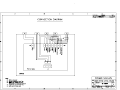
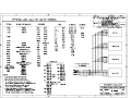
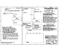
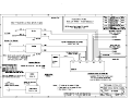
4. Control Drawing, 02-88060 ..................................................
Page 10
***SPECIAL NOTE***
Doran Scales, Batavia, IL. is not responsible for the
installation, use, or damages as a result of the installation
or operation of the Model 8000MIS or the associated
equipment used with it.
The Intrinsic Safety of the application is the
responsibility of the customer and / or installer.
Page 1
1.
INTRODUCTION TO INTRINSIC SAFETY
1.0
INTRODUCTION
This document is provided to supply information on Intrinsic Safety as it applies to the
installation of Doran Scales equipment and accessories. Only Doran Scales approved equipment
and accessories shown on the Control Drawings are to be used with an Intrinsically Safe
application
***CAUTION***
The instruction and precautions in this document take precedence over
any information contained in the Doran Scales Model 8000 Operating and
Service Manual.
The installer/user should thoroughly read, be familiar with, and understand the requirements and
any precautions or procedure associated with Intrinsically Safe installations.
1.
WHAT IS FACTORY MUTUAL APPROVAL?
Factory Mutual Approval means that Factory Mutual, as an independent lab and as it applies to
Doran Scales, has tested and has given Entity approval for the Doran Scales Model 8000MIS for
use in Intrinsically Safe applications. The Model 8000MIS, when used with the proper
equipment and options, will be Intrinsically Safe when used as a part of an Intrinsically Safe
circuit.
The Model 8000IS scale system may incorporate any of the following and is limited to the listed
combinations:
1. Load cells- Only those listed on Control Drawing 02-88060 may be used
2. Model 8000MIS indicator
3. Model 8000BIS battery pack or Model 8000AIS AC/DC Power Supply
4. Cable
5. Optional Remote Switch
Refer to the Control Drawing (7 sheets) for the specific device and electrical specifications for
connection of the listed components.
Page 2
Please note that only load cells listed on the Control Drawing may be used with the Doran Model
8000MIS as specified in the load cell manufacturers Control Drawing. The use of the listed load
cell(s) ensures compatibility with the Doran Scale Model 8000MIS and can be installed in any
mechanical structure that supports the appropriate load cell.
1.2 FACTORY MUTUAL ADHERENCE REQUIREMENTS
The following is a synopsis of the requirements that must be satisfied for a Factory Mutual
approved installation.
i.
The Model 8000MIS indicator must have a nameplate indication FM approval
(class, group, division) for the specific hazardous location with the model number
and referencing the Control Drawing.
ii.
The Model 8000BIS battery pack must have a nameplate indicating model
number, temperature code and a reference for the Control Drawing.
iii.
The Model 8000AIS AC/DC power supply must have a nameplate indicating
F.M. approval (class, group, division) for the specific hazardous locations with
the model number, and referencing the Control Drawing. The 8000AIS is used in
place of the 8000BIS and 8000CIS.
iv.
All interconnections, wiring methods, sealing, fittings, grounding, etc. must be in
accordance with the National Electrical Code and Intrinsic Safety National
Standard.
v.
Only the device(s) listed in the Control Drawing may be used in the installation.
1.3 BARRIERS AND OPTIONS
The Model 8000MIS can support limited options for an Intrinsically Safe application. Only the
RS232 serial data output and a remote push-button (simple apparatus) are supported per the
Control Drawing. The Pepperl-Fuch barrier P/N Z366 or Z966 can be used with the RS232
serial data output with the appropriate wiring. The Pepperl-Fuch barrier P/N Z366 or Z966 can
be used to allow a remote push-button in the safe area.
Barriers, buss bars and associated barrier hardware can be purchased as option from Doran
Scale, Inc.
Page 3
For customer supplied interfaces and devices, the following must be met:
i.
Cable and /or accessories must be exactly wired as illustrated in the Control
Drawing.
ii.
Only barriers listed in the Control Drawing can be used.
iii.
A tamper proof ground must be supplied as shown to all barriers and equipment
in a single point configuration to eliminate any ground potentials. Ground
connections should be less that 1 ohm.
iv.
Requirement that the remaining circuits must not generate or be connected to any
voltage in excess of 250 volts must be observed
2. UNPACKING AND INSTALLATION
2.1 OVERVIEW
Installation of all electrical equipment including indicator, barriers, and associated scaling must
be in compliance with the National Electrical Code and the Intrinsic Safety National Standard.
2.2 SCALE INSTALLATION
Scale installation involves locating the platform or weighing element(s) in the hazardous area
and mounting the Model 8000MIS in a secure location, also in the hazardous area. The power
for the Model 8000MIS can be provided by the Model 8000BIS rechargeable battery or the
Model 8000AIS AC/DC Power Supply. The Model 8000BIS is the standard configuration and
the Model 8000AIS is the alternate configuration and replaces the Model 8000BIS and Model
8000CIS. Both versions can not be utilized at the same time.
The use of conduit for options is not required except by the Plant Engineer’s preference. All
seals and accessories required to make the proper installation and maintain the separation of the
hazardous and safe areas are the responsibility of the customer.
It is also recommended that any cable runs that are part of the Intrinsically Safe circuit be
marked with a bright blue tape. Blue cable could also be utilized.
All Intrinsically Safe wiring should be located not less than 2 inches from Non-Intrinsically Safe
wiring, unless separated by an insulating or ground partition.
***CAUTION***
Although the Model 8000MIS is approved as being Intrinsically safe,
caution should always be observed in all areas designated as hazardous
including the use of tools and equipment
Page 4
***CAUTION***
If there are any doubts of whether the area is hazardous, the circuit is
Intrinsically Safe, or any questions about the installation, consult the Plant
Engineer or personnel responsible for the installation.
All installation and / or maintenance should be coordinated with the plant
engineer or the responsible personnel.
The scale should be securely mounted using the supplied mounting bracket to a table, wall or
under a cabinet to prevent the scale indicator from being accidentally dropped or damaged. The
indicator should be mounted for easy removal of the battery pack for recharging purposes.
2.2.1 INSTALLATION UTILIZING THE MODEL 8000BIS/8000CIS
In all cased, the indicator ( Model 8000MIS ) and the battery pack (Model 8000BIS) will be
installed as a complete unit and at the same time the platform is installed. The Model 8000MIS
and the Model 8000BIS are both considered Intrinsically Safe as an assembly unless there are
options that need to be connected to the indicator (i.e. RS232 or remote switch). Once the
options are installed per the Control Drawing and the electrical circuit has been determined to be
Intrinsically Safe, then the complete assembly with the options can be considered Intrinsically
Safe.
The Model 8000IS system when ordered with a platform includes the platform ( unless specially
ordered ), Model 8000MIS indicator, Model 8000BIS battery pack and Model 8000CIS battery
charger.
2.2.1.1 MODEL 8000BIS/8000MIS TYPE (D) INSTALLATION
The Model 8000MIS, Model, 8000BIS and the platform are approved for use in the hazardous
area per the Control Drawing. The Battery pack must be removed from the hazardous are and
taken into the safe area to be recharged with the Model 8000CIS. The Model 8000CIS battery
charger MUST be located in the Safe area and is NOT Intrinsically Safe. The battery
charger has two indicators on the top of the charger unit. The READY light will be on when the
charger is plugged into 115VAC (220VAC optional). If the READY light remains off, 115VAC
is not present, the battery is shorted, or the charger has a blown fuse. The CHARGING light will
be on as long as charging current is supplied to the battery output connector. The battery is
charged when the CHARGING light goes out.
The Model 8000BIS will operate the Model 8000MIS indicator for approximately 80 hr’s (single
load cell), after which the “BATT” enunciator on the face of the indicator will flash periodically
to alert the operator that the battery pack needs recharging. To recharge the battery pack,
unscrew the connector on the back of the indicator and loosen the two small knobs on the side of
the mounting bracket and gently pull on the handle to remove the battery pack from the
mounting bracket. Once removed from the mounting bracket, take the battery pack connector
into the battery charger connector. The battery pack will require about 24 hours to fully
recharge. Once the time has elapsed, unplug the battery pack from the battery charger and take
the battery pack into the hazardous area where the indicator is and place the battery pack in the
mounting bracket. Once in place, tighten the two knobs on the sides of the mounting bracket to
Page 5
secure the battery pack. Plug the battery pack connector back into the indicator connector on the
back of the indicator. The scale is now ready for use again.
An optional extra battery pack can be ordered for situations that require uninterrupted operation
of the scale. The battery pack may be left plugged in the charger until ready to use.
For multiple load cell applications, battery life is significantly reduced. For example, with a
four, 350 ohm load cell configuration, the low battery indication will begin at about 4 to 6 hours
of continuous use a fully charged battery. After the low battery begins to flash, the indicator will
operate for approximately 10 more hours before the indicator will shut off. Load cells with
higher input impedance values will provide longer life as will systems with fewer load cells.
2.2.2 INSTALLATION UTILIZING THE MODEL 8000AIS
The Model 8000AIS is an AC/DC power supply that can be used for more permanent
installations. The Model 8000BIS/CIS are not required in this installation. The power supply is
designed to be intrinsically safe and can be mounted in the hazardous are following the Control
Drawing. The power supply can also be mounted in the safe are with the output entering the
hazardous area through an isolation wall utilizing proper sealing. The power supply can be
thought of as a barrier and barrier installation techniques should be utilized when installing the
power supply.
The power supply can be ordered for either 115VAC or 220VAC, 50/60 Hz operation. The
selection is not a field selection since the entire power supply is potted and is not field
accessible. The power supply will cease to function under fault conditions ( over voltage, excess
current, etc.) See section 2.2.5 for more information. The power supply must be returned to
Doran Scales, Inc. for service if it fails to operate.
2.2.3 MODEL 8000AIS- TYPE A INSTALLATION
The Model 8000AIS can be installed within the hazardous area following the proper guidelines
outlined in the Control Drawing. An adapter cable is supplied with the Model 8000MIS when
ordered with the AC/DC power supply option for connection to the Model 8000AIS directly or
through the use of an interconnect cable assembly. If the extension interconnect cable is
required, se section 2.2.5.
When only the adapter cable is utilized, the power supply must be mounted within 2 feet of the
8000MIS. The model 8000AIS power supply and the Model 8000MIS must be securely
mounted. The plug on the power cord supplied should be cut off and the strain relief around the
cord removed from the power supply. The Model 8000AIS must have rigid threaded 1/2 inch
conduit installed. The cord is then routed through the rigid conduit to a junction box approved
for the classification for the are. The power connection is then completed in this junction box.
The conduit must the exit the hazardous are through the isolation wall with the proper sealing
requirements follower and connections made to the AC power.
Page 6
2.2.4 MODEL 8000AIS - TYPE B INSTALLATION
The Model 8000AIS can be installed within the safe area following the proper guidelines
outlined in the Control Drawing. An adapter cable is supplied for interfacing with a interconnect
cable that exits the hazardous area though an isolation wall. The interconnect cable makes the
connection to the AC/DC power supply within the safe area. The DC output of the power supply
is considered Intrinsically Safe and should be treated as an intrinsically safe output from a
barrier.
WARNING!
NON-WARRANTY DAMAGE TO THE POWER SUPPLY IS LIKELY IF
THE OUTPUT IS CONNECTED TO A SHORTED OR LOW
IMPEDANCE CIRCUIT. THE DC POWER CIRCUIT TO THE 8000MIS
SHOULD BE CHECKED WITH AN OHMMETER BEFORE APPLYING
POWER TO THE 8000AIS POWER SUPPLY. A READING OF LESS
THAN 1000 OHMS INDICATES A PROBLEM. DO NOT APPLY
POWER UNTIL THE CAUSE OF THE LOW
IMPEDANCE IS FOUND AND CORRECTED.
Once mounted in the safe area, the Model 8000AIS can be connected to the proper power supply
utilizing the supplied power cord.
2.2.5 INTERCONNECT CABLE
The interconnect cable is assembled utilizing the supplied plug and receptacle and customer
supplied cable. The interconnect cable is simply used to extend the adapter cable in situations
that require a longer run of cable between the Model 8000AIS and Model 8000MIS . The gauge
and length of wire must be as specified in the Control Drawing (02-88060),
WARNING!
NON-WARRANTY DAMAGE TO THE POWER SUPPLY IS LIKELY IF
THE OUTPUT IS CONNECTED TO A SHORTED OR LOW
IMPEDANCE CIRCUIT. THE DC POWER CIRCUIT TO THE 8000MIS
SHOULD BE CHECKED WITH AN OHMMETER BEFORE APPLYING
POWER TO THE 8000AIS POWER SUPPLY. A READING OF LESS
THAN 1000 OHMS INDICATES A PROBLEM. DO NOT APPLY
POWER UNTIL THE CAUSE OF THE LOW IMPEDANCE IS FOUND
AND CORRECTED.
When assembling the cable, the mating receptacle is placed at the end that interfaces with the
adapter cable and the plug is mounted at the end that interfaces to the Model 8000AIS.
Page 7
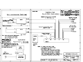
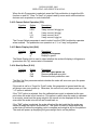
The legend for the 3 conductor connector is:
Receptacle (to Adapter Cable)
Pin A DC+ Power
Pin B DC- Power
Pin C Chassis Ground
Pin C - Shield
3.0
Plug (to Power Supply)
Pin A -DC+ Power
Pin B - DC- Power
Pin C - Chassis Ground
Pin C - Shield
to
to
to
to
MULTIPLE LOAD CELL AND BATTERY LIFE CONSIDERATIONS
The 8000IS Battery Powered and 8000AIS Line Powered Intrinsically Safe Indicators can be
used in multiple load cell installations. Under all circumstances, the requirements of the Doran
Control Drawing 02-88060 Rev. 10 must be met- refer to this for all installations.
1) Multiple load cell scales There are several precautions you must be aware of when using the
Doran 8000IS or 8000AIS in multiple load cell applications.
i.
8000IS or 8000AIS: For maximum scale performance, when using either
indicator with a multiple load cell installation, matched output load cells are
recommended as the FM control drawing does not allow trimming components.
ii.
8000IS or 8000AIS AC Line Powered Indicator: Up to four (4) of any of the load
cells listed on the approval chart on page 5 of the Doran control drawing 0288060 Rev. 10 can be connected to the 8000AIS AC Line Powered Indicator.
iii.
8000IS Battery Powered Indicator: When multiple load cells are connected to
the 8000IS Battery Powered Indicator, the battery life will be decreased as
described in the manual. Further, Doran does not recommend connecting and
overall load lower than 175 ohms resistance on the excitation terminals of the
8000IS Battery Powered Indicator. The overall load is the input (excitation)
resistance of one load cell divided by the number of load cells (e.g., four 1000
ohm load cells represent a load of 1000 / 4 = 250 ohms.) The use of four 700
ohm load cells (overall load of 175 ohms) will degrade the battery life between
charging to about 36 hours. Use of an overall load lower than 175 ohms will
greatly decrease battery life or will not allow the 8000IS to function at all. Thus,
four 350 ohm load cells will not work with the 8000IS Battery Powered Indicator.
When using the 8000IS with multiple load cells, we recommend using 1000 ohm
cells, such as the Revere SSB-D1 or HBM BLC or HBM TWM type.
2) Single load cell scales: Both the 8000IS Battery Powered and 8000AIS AC Line Powered
Intrinsically Safe Indicators can be used with any one (1) of the load cells listed on the approval
chart on page 5 of the Doran control drawing 02-88060 Rev. 10 without any degradation of
performance
Page 8
4. TROUBLE SHOOTING AND SYSTEM OVERVIEW
The troubleshooting of the Model 8000MIS should occur in the safe are and employ the use of
spark-proof tools. Also, observe any safety precautions and equipment that may be required
either by the installation of the customer. Follow the Model 8000 Operating and Service Manual
for troubleshooting the scale portion of the installation. Any type of part replacement and for
repair will require the assembly to be returned to Doran Scales, Batavia, IL. This will ensure
that any repair to the assembly will remain in compliance with the F.M. approval.
***WARNING***
THERE ARE NO FIELD SERVICEABLE COMPONENTS IN THE
8000IS SYSTEM.
Any repair or replacement of components will require the assembly be
returned to the factory Doran Scales, Batavia, IL for repair.
Call the factory to obtain an RMA ( Return Material Authorization
Number) before returning any equipment for repair.
This concludes the Intrinsically Safe portion of the installation of the scale system. Consult the
Model 8000 Operating and Service Manual for information regarding the operation of the scale.
Page 9
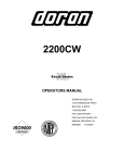
Model
8000
Digital Scale
OPERATING AND SERVICE MANUAL
DORAN SCALES INC.
1315 PARAMOUNT PKWY.
BATAVIA, IL. 60510
1-800-262-6844
FAX: (630) 879-0073
http://www.doranscales.com
MAN0002
2/03/00
MANUAL REVISION:
4.2
SOFTWARE REVISION: 4.3
Made in USA
DORAN MODEL 8000
OPERATING AND SERVICE MANUAL
1. INTRODUCTION ......................................................................................................... 3
2. UNPACKING AND INSTALLATION ........................................................................... 3
2.1
2.2
2.3
2.4
2.5
CAUTIONS ............................................................................................................................................................... 3
UNPACKING ............................................................................................................................................................ 4
LOCATING THE SCALE .......................................................................................................................................... 4
SET UP..................................................................................................................................................................... 4
OVERLOAD STOPS ................................................................................................................................................ 4
3. PROGRAMMING THE 8000........................................................................................ 4
3.1
3.2
3.3
3.4
INTRODUCTION ...................................................................................................................................................... 4
ENTERING THE "USER SET-UP MENU” ............................................................................................................... 5
TO SET OR REVIEW PARAMETER SETTINGS .................................................................................................... 5
USER SET-UP PARAMETERS ............................................................................................................................... 6
4. USING THE 8000 ...................................................................................................... 14
4.1
4.3
4.4
4.5
4.6
FRONT PANEL CONTROLS AND INDICATORS ................................................................................................. 14
SCALE OPERATION.............................................................................................................................................. 15
BATTERY CHARGING (8000M ONLY)................................................................................................................... 17
LOW BATTERY INDICATION ................................................................................................................................ 18
OVERLOADS ......................................................................................................................................................... 18
5. USING THE DATA INTERFACE ............................................................................... 18
5.1 INTRODUCTION .................................................................................................................................................... 18
5.2 DATA TRANSMISSION MODES ........................................................................................................................... 18
5.4 DEFINITION OF TERMS: .............................................................................................................................................. 20
6. CALIBRATING THE 8000 ......................................................................................... 21
6.1
6.2
6.3
6.4
6.5
6.6
6.7
INTRODUCTION .................................................................................................................................................... 21
ENTERING THE CALIBRATION MODE................................................................................................................ 21
ANALOG ZERO CALIBRATION ............................................................................................................................ 21
ANALOG SPAN CALIBRATION............................................................................................................................. 22
DIGITAL CALIBRATION......................................................................................................................................... 23
EXITING THE CALIBRATION MODE .................................................................................................................... 23
ERROR CODE TABLE........................................................................................................................................... 24
7. TROUBLESHOOTING .............................................................................................. 25
7.1
7.2
7.3
7.4
PROBLEMS/SOLUTIONS...................................................................................................................................... 26
CONFIGURATION PRINTOUT FOR REVISION 3.6 AND GREATER. ............................................................................ 27
INITIAL PARAMETER REVIEW FOR REVISION 4.2 AND GREATER. ..................................................................................... 27
RESETTING PARAMETERS ................................................................................................................................. 27
8. MODEL 8000 TECHNICAL SPECIFICATIONS ........................................................ 27
9. CONNECTIONS AND OTHER .................................................................................. 30
9.1
9.2
9.3
9.4
9.5
9.6
9.7
RS232 SIMPLEX PORT ......................................................................................................................................... 30
20MA SIMPLEX PORT ............................................................................................................................................ 30
POWER SUPPLY CONNECTIONS ....................................................................................................................... 30
REMOTE SWITCHES ............................................................................................................................................ 30
BATTERY CONNECTIONS ................................................................................................................................... 29
MISCELLANEOUS CONNECTORS AND SWITCHES.......................................................................................... 31
LOAD CELL CONNECTIONS ................................................................................................................................ 31
10. CONFIGURATION FOR SSP/DLP PRINTER:....................................................... 32
11. CAPACITY LABELS: ............................................................................................. 33
1. INTRODUCTION
MAN0002-42
2 of 33
DORAN MODEL 8000
OPERATING AND SERVICE MANUAL
Congratulations! You have chosen the most technologically advanced, highest quality
stainless steel battery operated scale available today. The Doran Scales Model 8000
incorporates state-of-the-art CMOS microprocessor technology, a high energy-density
rechargeable battery, and leading edge low power LED displays to provide the ultimate
in scale power, portability and flexibility. This combination of leading edge electronics,
rugged stainless steel gasketed construction and high quality water resistant doublecapacity load cell is designed to provide the highest degree of accuracy while
maintaining the durability necessary to hold up to hostile industrial environments.
Major features of the 8000 that set it apart from other scales are:
* Legal for Trade operation
* Rechargeable battery.
* 40 hours of continuous use from a 4 hour charge (except for 8000MIS model. See
Factory Mutual manual for this model).
* Self contained charger.
* Scale operates on AC during recharge.
* Automatic pushbutton calibration.
* Pushbutton ON/RESTART, TARE, ZERO, CONV and PRINT.
* Bright, easy to read LED display.
* Read weight in LB, KG, G, OZ and LB & OZ.
* User programmable features include: -on timer
-display update rate/averaging
-zero tracking
-display capacity and resolution
-serial data output configuration
Please be sure to read this entire manual to assure yourself of getting all the benefits of
these and the other advanced features of the Doran Scales Model 8000.
This scale is backed by a full 2 year factory warranty. Should you have any problems,
contact your authorized Doran Scales distributor or call Doran Scales' Technical
Support department direct at 1-800-262-6844 for assistance. Do not return a scale to
the factory without first obtaining a Return Material Authorization (RMA) number.
2. UNPACKING AND INSTALLATION
2.1 CAUTIONS
Before unpacking your Model 8000, please note that although it is a durable industrial
scale, it is also a sensitive weighing instrument. Normal care should be taken when
handling and using the scale. Please observe the following precautions to insure years
of trouble free service from your Model 8000.
* DO NOT drop the scale platform or indicator.
* DO NOT drop objects onto the scale platform.
* DO NOT immerse the scale platform or indicator.
* DO NOT pick up the scale platform by the "spider"
Improper handling or abuse of the scale could be damaging and result in costly repairs
to your unit which may not be covered under warranty.
MAN0002-42
3 of 33
DORAN MODEL 8000
OPERATING AND SERVICE MANUAL
2.2 UNPACKING
Carefully remove the scale platform, the indicator and the platter from the shipping
carton. Be sure to retain the shipping carton and all packing material in case
reshipment is required. Note that the indicator and platform are connected by a 5'
cable; be careful not to pull too hard on this cable.
2.3 LOCATING THE SCALE
The Model 8000 requires 115VAC, 50/60 Hz power (220VAC optional) for charging. Be
sure that the AC power is not too noisy - this can occur if large inductive loads, like
solenoids or motors are on the same power line. The 8000 has a filtered power supply
to reduce the effects of normal line noise, but it cannot limit severe noise.
Choose a location that is sturdy and free from vibration and air currents. Vibration from
heavy equipment and air currents from fans, heating ducts, etc. can cause the scale
display to fluctuate. Using the Model 8000's Digital Averaging feature to minimize these
effects is outlined in Section 3 of this manual.
2.4 SET UP
Place the scale platform in its desired location. Level the platform by adjusting the four
corner feet until the bubble in the bubble level, located beneath the top platter of the
platform, is within the center circle. After a level condition is achieved, test for a stable
condition by trying to rock the platform backward and forward and side to side. Adjust
the feet for final levelness and stability.
Locate the desired position for the scale indicator. If the indicator is to be permanently
mounted to a wall, shelf or counter, remove the mounting bracket from the indicator.
Use the two holes provided in the bracket to affix it to the desired location. Reassemble
the 8000 indicator to the bracket. Loosely thread the two knobs back onto the studs.
Adjust the indicator to its desired viewing angle and tighten down the knobs.
2.5 OVERLOAD STOPS
There are several overload stops in the base of the scale that are factory set. Do Not
adjust these stops as adjustments may void any warranty claims. Consult the service
department if adjustment is needed.
3. PROGRAMMING THE 8000
3.1 INTRODUCTION
The 8000 can be configured for each application through the "user set-up menu" in the
8000. The "user set-up menu" allows you to program things like how often the display is
refreshed , how the data output works, scale capacity,resolution, and more. Each 8000
is programmed at the factory to the most common settings.
Read the description of each of the parameters and set each one to best fit your
application. If you are unsure of the parameter setting you need, a trial and error
process will assist you. If a parameter setting is not suitable, you can try a different
setting very easily. If you run into problems, you can contact the Doran Scales service
department for advice on the set-up of your 8000.
MAN0002-42
4 of 33
DORAN MODEL 8000
OPERATING AND SERVICE MANUAL
3.2 ENTERING THE "USER SET-UP MENU"
1. Remove the small access panel on the rear of the scale indicator by removing the
two hex screws holding the panel in place.
2. Flip SW1 located on the PCB inside the access port (red toggle handle switch).
3. The scale display will display the message AUG --.
3.3 TO SET OR REVIEW PARAMETER SETTINGS
Programming the 8000 is done by pressing the TARE and ZERO buttons on the front
panel of the indicator.
To change or review parameter settings, simply step through each parameter by
pressing ZERO and select the desired option by pressing TARE.
1. Press ‘ZERO’ to increment the parameter shown on the left of the display.
2. Press TARE to increment the option shown on the right of the display. Each
parameter has several options to select from that affect scale operation.
3. Flip SW1 back to its original position (inboard) to return to normal operation. This
can be done at any point in the set up menu.
4. Replace the access cover on the back of the unit to maintain its water resistant and
dust-tight integrity.
Configuration is permanently saved in a nonvolatile EEPROM (Electronically
Erasable/Programmable Read-Only Memory).
3.3.1 Table of User Setup Parameters
Parameter
AVG
AZT
b.r.
d.o.
S.U.
CAP
tdy
oP
P.b.
CtS
d.b.p
hSh
CSL
SLU
S.U.0
MA
PFt
MAN0002-42
Default settings are in bold.
Description
Digital Averaging
Auto Zero Tracking
Baud Rate
Data Output Mode
Start up unit
Scale Capacity
Unit On Timer
Operating Mode
Push Button Operation
Total Number of Graduations
Data Bits and Parity
Clear to Send Enable
Convert Select Operation
Metric Display Unit
Start Up Zero
Motion Aperature
Print Format
5 of 33
Options
A1,1,2,4,8,16,A2
.5,1,3,OFF
960,480,240,120,30
tod,Cnt,AP1,AP2,AP3,L.O.d.
Lb,kg,oz,L O
1.3 thru 120
.5,1.0,1.5,2.0,3.0,5.0,10.0,30.0
Std,44,CAn
non,C,P,CP,Pd,CPd
3,6,10
8n,7n,7O,7E
OFF,ON
CA,LGO,LG,LO,GO
kg,g
--0,CL0,Pb0
1,3,5
1,2,3,4,5,6
DORAN MODEL 8000
OPERATING AND SERVICE MANUAL
3.4 USER SET-UP PARAMETERS
The following is a detailed list of the parameters and options in the 8000. Be sure to
read this carefully, and select settings that will best fit the application.
NOTE: Factory default settings are shown in bold type.
3.4.1 Digital Averaging or Display Update Rate (AVG)
Function
AVG
Option
A1
1*
2
4
8
16
A2
Description
Approx. 10 updates/second
Approx. 10 updates/second
Approx. 5 updates/second
Approx. 2 updates/second
Approx. 1 updates/second
Approx. .5 updates/second
Approx. 10 updates/second
* Refers to the number of reading per average cycle
The Digital Averaging parameter is used to tailor the 8000's display update rate to your
application and environment. The circuitry in the 8000 takes weight readings at a rate
of approximately 10 per second.
Factors such as wind currents and vibrations can be read as changes by the scale's
weight sensor, thus 10 updates per second is too fast and the scale display appears to
be "bouncy". In order to filter or "smooth" out the display, the 8000 is equipped with an
averaging function.
The averaging function takes a series of weight readings and averages them together.
This smooths out the small changes caused by outside influences. The more readings
taken, the more stable the display will be.
However, as this number of readings per average increases, the update rate of the
display updates slows down. The above chart shows the relationship between the
number of readings per average and the display update rate.
The "A1" and "A2" setting refer to a software utility called "Auto Averaging". The update
rate of the display varies based upon the amount of motion taking place on the scale
platform.
"A1" allows for maximum speed of weighing while maintaining high stability at the final
weight reading. "A2" provides a more stable final weight reading than A1.
3.4.2 Automatic Zero Tracking (AZT)
Function
AZT
MAN0002-42
Option
.5
1
3
OFF
Description
+/- .5 div zeroed
+/- 1 div zeroed
+/- 3 div zeroed
none
6 of 33
DORAN MODEL 8000
OPERATING AND SERVICE MANUAL
Automatic Zero Tracking is used to compensate for small deviations from zero caused
by such things as slight air currents or material left on the scale platform.
Automatic Zero Tracking will measure this deviation every scale update, and if it is
within the specified range of scale divisions, it will automatically re-zero the scale.
Adjust the Zero Track Aperture so that it best fits your application.
If you are working with minute weights that are near zero, it is advisable to turn
Automatic Zero Tracking off, as it may interfere with the weighments.
When set for a Legal for Trade operating mode ("44" or "CAN"), only the "off" or ".5"
option is allowed for this parameter.
3.4.3 Baud Rate Selection (b.r.)
Function
b.r.
Option
960
480
240
120
30
See Section 5 for more information
Description
9600 baud
4800 baud
2400 baud
1200 baud
300 baud
3.4.4 Serial Data Output Mode (d.o.) See Section 5 for a detailed explanation
Function
d.o.
Option
tod
Cnt
AP1
AP2
AP3
L.O.d.
Description
Transmit on Demand
Continuous Transmission
Auto Print 1
Auto Print 2
Auto Print 3
Latch on Demand
3.4.5 Start-Up Unit (S.U.)
Function
S.U.
Option
Lb
hg
oz
*L O
Description
Start-up in "lb
Start-up in "kg or g"
Start-up in "oz"
Start-up in "lb & oz"
The Start-Up Unit is the weight display unit that the 8000 displays in when the scale is
turned on. Select the unit that is most frequently used as your start-up unit.
The lb & oz unit can only be selected for 1, 3, 5, 10, 15, 20, 30, 60, 100, 120, 150, 200,
and 300 pound capacities for 3000 displayed graduations and 3, 5, 10, 20, 30, 60, 100,
200, 300, 500, and 600 pound capacities for 6000 displayed graduations.
Note: When the operating mode of the 8000 (see below) is set to HB44 or CAN (Legal
for Trade), the "lb & oz" weight display mode will not function since it is not
recognized as a legal for trade display unit.
MAN0002-42
7 of 33
DORAN MODEL 8000
OPERATING AND SERVICE MANUAL
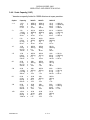
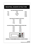
3.4.6 Scale Capacity (CAP)
* denotes a capacity limited to 10000 divisions at super precision.
Option
Capacity
3000 D
6000 D
10000 D
*1.3
1.3 lb
.6 kg
(600 g
21 oz
x
x
x
x
.0005 lb
.0002 kg
.2 g
.01 oz
.0002 lb
.0001 kg
.1 g
.005 oz
1.0 lb
.45 kg
454 g
16 oz
x
x
x
x
.0001 lb
.00005 kg
.05 g)
.002 oz
*3
3 lb
1.36 kg
(1.36 kg
48 oz
x
x
x
x
.001 lb
.0005 kg
.5 g
.02 oz
.0005 lb
.0002 kg
.2 g
.01 oz
2.0 lb
.9 kg
900 g
32 oz
x
x
x
x
.0002 lb
.0001 kg
.1 g)
.005 oz
5
5 lb
2.3 kg
(2.3 kg
80 oz
x
x
x
x
.002 lb
.001kg
1g
.05 oz
.001lb
.0005 kg
.5 g
.02 oz
.0005 lb
.0002 kg
.2 g)
.01 oz
10
10 lb
4.5 kg
(4.5 kg
160 oz
x
x
x
x
.005 lb
.002 kg
2g
.1 oz
.002 lb
.001kg
1g
.05 oz
.001 lb
.0005 kg
.5 g)
.02 oz
*15
15 lb
6.8 kg
(6.8 kg
240 oz
x
x
x
x
.005 lb
.002 kg
2g
.1 oz
.002 lb
.001 kg
1g
.05 oz
10 lb
4.5 kg
4.5 kg
160 oz
x
x
x
x
.001 lb
.0005 kg
.5 g)
.02 oz
20
20 lb
9.1kg
(9.1 kg
320 oz
x
x
x
x
.01lb
.005 kg
5g
.2 oz
.005 lb
.002 kg
2g
.1 oz
.002 lb
.001 kg
1g)
.05 oz
*30
30 lb
13.6 kg
(13.6 kg
480 oz
x
x
x
x
.01lb
.005 kg
5g
.2 oz
.005 lb
.002 kg
2g
.1 oz
20 lb
9.1 kg
9.1 kg
320 oz
x
x
x
x
.002 lb
.001 kg
1g)
.05 oz
50
50 lb
23 kg
(23 kg
800 oz
x
x
x
x
.02 lb
.01kg
10 g
.5 oz
.01lb
.005 kg
5g
.2 oz
.005 lb
.002 kg
2 g)
.1 oz
*60
60 lb
27 kg
(27 kg
960 oz
x
x
x
x
.02 lb
.01kg
10 g
.5 oz
.01lb
.005 kg
5g
.2 oz
50 lb
23 kg
23 kg
800 oz
x
x
x
x
.005 lb
.002 kg
2 g)
.1 oz
100
100 lb
45 kg
(45 kg
1600 oz
x
x
x
x
.05 lb
.02 kg
20 g
1 oz
.02 lb
.01kg
10 g
.5 oz
.01 lb
.005 kg
5 g)
.2 oz
MAN0002-42
8 of 33
DORAN MODEL 8000
OPERATING AND SERVICE MANUAL
*120
120 lb
54 kg
(54 kg
1920 oz
x
x
x
x
.05 lb
.02 kg
20 g
1 oz
.02 lb
.01kg
10 g
.5 oz
100 lb
45 kg
45 kg
1600 oz
x
x
x
x
.01 lb
.005 kg
5 g)
.2 oz
*150
150 lb
68 kg
(68 kg
2400 oz
x
x
x
x
.05 lb
.02 kg
20 g
1 oz
.02 lb
.01kg
10 g
.5 oz
100 lb
45 kg
45 kg
1600 oz
x
x
x
x
.01 lb
.005 kg
5 g)
.2 oz
200
200 lb
91 kg
(91 kg
3200 oz
x
x
x
x
.1lb
.05 kg
50 g
2 oz
.05 lb
.02 kg
20 g
1oz
.02 lb
.01kg
10 g)
.5 oz
*300
300 lb
136 kg
4800 oz
x
x
x
.1 lb
.05 kg
2 oz
.05 lb
.02 kg
1 oz
200 lb
x .02 lb
91 kg
x .01 kg
3200 oz x .5 oz
500
500 lb
227 kg
8000 oz
x
x
x
.2 lb
.1kg
5 oz
.1lb
.05 kg
2 oz
.05 lb
.02 kg
1 oz
*600
600 lb
272 kg
9600 oz
x
x
x
.2 lb
.1kg
5 oz
.1lb
.05 kg
2 oz
500 lb
x .05 lb
227 kg
x .02 kg
8000 oz x 1 oz
750
750 lb
x
340 kg
x
12000 oz x
.5 lb
.2 kg
10 oz
.2 lb
.1 kg
5 oz
.1 lb
.05 kg
2 oz
1.
1000 lb
x
450 kg
x
16000 oz x
.5 lb
.2 kg
10 oz
.2 lb
.1 kg
5 oz
.1 lb
.05 kg
2 oz
2.
2000 lb
x
910 kg
x
32000 oz x
1lb
.5 kg
20 oz
.5 lb
.2 kg
10 oz
.2 lb
.1 kg
5 oz
*3.
3000 lb
x
1360 kg x
48000 oz x
1 lb
.5 kg
20 oz
.5 lb
.2 kg
10 oz
2000 lb x .2 lb
910 kg
x .1 kg
32000 oz x 5 oz
5.
5000 lb
x
2270 kg x
80000 oz x
2 lb
1 kg
50 oz
1 lb
.5 kg
20 oz
.5 lb
.2 kg
10 oz
*6.
6000 lb
x
2720 kg x
96000 oz x
2 lb
1 kg
50 oz
1 lb
.5 kg
20 oz
5000 lb x .5 lb
2270 kg x .2 kg
80000 oz x 10 oz
10.
10000 lb x
4500 kg x
160000 oz x
5 lb
2 kg
100 oz
2 lb
1 kg
50 oz
1 lb
.5 kg
20 oz
*15.
15000 lb x
6800 kg x
240000 oz x
5 lb
2 kg
100 oz
2 lb
1 kg
50 oz
10000 lb x 1 lb
4500 kg x .5 kg
16000 oz x 20 oz
20.
20000 lb x
9100 kg x
320000 oz x
10 lb
5 kg
200 oz
5 lb
2 kg
100 oz
2 lb
1 kg
50 oz
MAN0002-42
9 of 33
DORAN MODEL 8000
OPERATING AND SERVICE MANUAL
*30.
30000 lb x
13600 kg x
480000 oz x
10 lb
5 kg
200 oz
5 lb
2 kg
100 oz
20000 lb x 2 lb
9100 kg x 1 kg
32000lb x 50 oz
50.
50000 lb x
22700 kg x
800000 oz x
20 lb
10 kg
500 oz
10 lb
5 kg
200 oz
5 lb
2 kg
100 oz
75.
75000 lb x
34000 kg x
50 lb
20 kg
20 lb
10 kg
10 lb
5 kg
100.
100000 lb x
45000 kg x
50 lb
20 kg
20 lb
10 kg
10 lb
5 kg
*120.
120000 lb x
54400 kg x
50 lb
20 kg
20 lb
10 kg
10000 lb x 10 lb
45000 kg x 5 kg
"Scale Capacity" defines the capacity that the display will read out. See Section 3.4.10
for information on the selection of the total displayed graduations for the resolution
displayed with the selected capacity. It is used to match the scale indicator to the scale
platform.
In most cases, the factory has already selected the proper capacity to match the scale
platform that is supplied with the indicator. Should it be necessary to change the
capacity of the indicator, make sure that the proper capacity label from the label sheet
provided is inserted into the capacity window of the faceplate of the indicator.
Refer to Section 6 on Calibrating the 8000 to make sure that the scale is properly
calibrated after changing the capacity.
Refer to Section 3.4.8 Operating Mode for legal for trade restrictions.
3.4.7 Unit On Timer (tdy)
Function
tdy
Option
on
.5
1.0
1.5
2.0
3.0
5.0
10.0
30.0
Description
on/off thru "ON/ZERO"
30 second "On Timer"
1 minute
"
1.5 minute
"
2 minute
"
3 minute
"
5 minute
"
10 minute
"
30 minute
"
The "On Timer" governs the amount of time the 8000 stays on after ON/RESTART is
pressed. The electronics in the 8000 sense activity on the scale platform - when there
is no activity on the platform within the time programmed for the "On Timer", the 8000
will turn itself off. Each time there is activity (motion) on the scale platform or any
pushbutton activity before the scale turns off, the "On Timer" is reset for its full time
period.
Remember that the 8000 provides up to 40 hours of continuous operation on a 4-hour
recharge (except for the 8000MIS model).
MAN0002-42
10 of 33
DORAN MODEL 8000
OPERATING AND SERVICE MANUAL
If you have sufficient time to recharge frequently and use the scale often, you may
select longer on-times or continuous-on. If you use the scale briefly or infrequently,
shorter on- times are more desirable for longer battery life.
The ON/RESTART button will always act as an on/off control. When the unit is off, the
ON/RESTART turns the scale on for the specified period of time. The scale remains on
until the ON/RESTART is pressed and held for 2-3 seconds, turning the scale off, or
until the timer times out. If the ON/RESTART button is pressed momentarily,
depending on the setting of the "On-Timer", the timer will either be reset or the scale will
shut off (ON setting).
3.4.8 Operating Mode (oP)
Function
oP
Option
Std
44
CAn
Description
Standard (not Legal for Trade)
HB44 (Legal for Trade)
Canadian Weights and Measures (Legal for Trade)
The Operating Mode defines whether or not the 8000 will operate in a "Legal for Trade"
mode. In the "44" (Legal for Trade) mode, the 8000's ZERO button and "Auto Zero
Tracking" function will only zero out up to 1.9% of the scale's capacity in compliance
with the NIST Handbook 44. The reference point for this 1.9% band is the calibrated
zero or empty platform value.
Care should be taken to make sure that the scale platform is empty when the scale is
turned on to insure proper operation of the ZERO button. In addition, when either the
"44" or the "CAN" mode is selected, the "lb & oz" weight display mode is disabled, since
it is not recognized as a "Legal for Trade" weight display unit.
Also, when the "44" mode is selected, the total number of displayed graduations is
limited to 3000, otherwise 3000 or 6000 graduations are allowed. In the "CAN" mode, if
3000 divisions is selected, the total number of displayed divisions is limited to 3000, and
if 6000 divisions is selected, the total number of divisions is limited to 6000. The
extended resolution selection (10000 divisions) is not a legal for trade setting.
When the "Std" mode is selected, the ZERO button and "Auto Zero Tracking" function
will work through the full capacity of the scale. The "lb & oz" weight display will also
function normally, if selected.
3.4.9 Push Button Operation (P.b.)
Function
P.b.
Option
non
C
P
CP
Pd
CPd
Description
Neither CONV nor PRINT enabled
CONV only enabled
PRINT only enabled
Both CONV and PRINT enabled
PRINT only with transmit prompt
Both CONV and PRINT enabled
with transmit prompt
Each scale is equipped with a CONV and PRINT button.
MAN0002-42
11 of 33
DORAN MODEL 8000
OPERATING AND SERVICE MANUAL
The CONV button changes the weight display unit. This is necessary in applications
where there is a need to read equivalent weights in different units.
The PRINT button tells the 8000 to transmit weight data from its data interface to a
printer, computer or other peripheral device.
The 8000 provides the capability of enabling or disabling either of these functions.
If an option is selected for a transmit prompt, "P d" or "CPd", the display will show
"PrtOUt" when serial data is sent to the printer or computer.
3.4.10 Total Number of Graduations (CtS)
Function
CtS
Option
3
6
Description
3000 total scale grads.
6000 total scale grads.
Selects the scale graduations for each capacity. By selecting either 3 or 6, the function
will provide 3000 or 6000 graduations throughout the list of capacities.
Remember that if the "44" mode is selected, only 3000 graduations is allowed.
3.4.10.A Extended Graduations (CtS)
Function
CtS
Option
10
Description
10000 total scale grads.
To select 10000 graduations, press PRINT and 10000 graduations will be selected.
Note: The maximum resolution for the 8000 is limited to 10000d. All the super
precision capacities have been limited to 10000d.
3.4.11 Data Bits and Parity (d.b.P)
Function
d.b.P
Option
8n
7n
7O
7E
Description
8 data bits and no parity
7 data bits and no parity
7 data bits and odd parity
7 data bits and even parity
The Data Bits and Parity parameter selects the number of data bits and parity for each
character transmitted. For error checking, a parity bit can be selected for device(s) that
require it.
3.4.11.A Clear To Send Enable (hSh)
Function
hSh
MAN0002-42
Option
OFF
ON
Description
Clear to send disabled
Clear to send enabled
12 of 33
DORAN MODEL 8000
OPERATING AND SERVICE MANUAL
When the d.b.P parameter is selected, press the Print pushbutton to toggle the hSh
function on and off. "Clear To Send" is a signal used by some serial communications
devices such as printers to control data flow.
3.4.12 Convert Select Operation (CSL)
Function
CSL
Option
CA
LGO
LG
LO
GO
Description
Convert all
3-way convert, lb-kg(g)-oz
2-way convert, lb-kg(g)
2-way convert, lb-oz
2-way convert, kg(g)-oz
The Convert Select parameter is used to select how the CONV pushbutton operates
when enabled. The pushbutton can operate in a 4, 3, or 2 way configuration.
3.4.13 Metric Display Unit (SLU)
Function
SLU
Option
kg
g
Description
Display in kilograms
Display in grams
The Metric Display Unit is used to select whether the scale will display in kilograms or
grams when the "kg" annunciator is illuminated.
3.4.14 Start Up Zero (S.U.0)
Function
S.U.0
Option
--0
CL0
Pb0
Description
Auto zero upon power up
Restore calibrated zero point
Restore the last pushbutton zero
The Start Up Zero parameter selects whether the scale will auto zero upon the power
up of the unit.
If the scale is set for a "Legal for Trade" mode, this parameter is ignored and the unit
will always zero upon power up. Otherwise, the unit will only zero upon power up if the
"--0" option is selected.
If the "CL0" option is selected, then the calibrated zero point is reloaded as the zero
point when the scale is first turned on. This option is useful when the scale is calibrated
to an empty vessel and the gross weight in the vessel is to be displayed all the time,
even when the scale is turned off and turned back on.
If the "Pb0" option is selected, the scale will reload the last point that the scale was
zeroed at when the scale is first turned on. This option is useful in cases where the
scale shuts off before the weighing cycle is complete and weight is still on the platform.
The scale will power up displaying the gross weight that is on the platform.
MAN0002-42
13 of 33
DORAN MODEL 8000
OPERATING AND SERVICE MANUAL
3.4.15 Motion Aperture (MA)
Function
MA
Option
1
3
5
Description
1 division of change before motion
3 divisions of change before motion
5 divisions of change before motion
The Motion Aperture is used to select how many displayed divisions of motion must be
sensed before the unit will go into a motion state. If a "Legal for Trade" mode is
selected, the scale will default to 1 division for the motion aperture.
3.4.16 Print Format (PFt)
Function
PFt
Option
1
2
3
4
5
6
Description
Weight, "grs/net" label
Weight only
Weight, "grs/net" label,Tare
DGH output for analog output
A&D printer format output
Data string for SSP/DLP printer
4. USING THE 8000
4.1 FRONT PANEL CONTROLS AND INDICATORS
4.1.1 Pushbutton Functions
TARE
-
Press and release to enter a tare. The tare value will be entered
and switch the 8000 to net mode.
Press and hold for two or more seconds to clear and return the
8000 to the gross mode.
ON/RESTART -
Press and release to turn the 8000 on.
Press and hold for 2-3 seconds to turn off.
ZERO
-
Zeros the scale. Active only in the gross mode.
See details below concerning Legal for Trade operation of the
ZERO function.
CONV
-
Changes the weight display unit each time it is pressed.
The sequence is lb-kg(g)-oz-lb & oz.
PRINT
-
Causes the data interface to transmit weight data.
MAN0002-42
14 of 33
DORAN MODEL 8000
OPERATING AND SERVICE MANUAL
4.2.2 Status Annunciators
lb
-Weight display is in pounds.
kg
-Weight display is in kilograms or grams.
oz
-Weight display is in ounces.
lb & oz -Simultaneous "lb" and "oz" annunciators indicate weight displayed in
pounds and ounces.
NEG
-Indicates negative weights in the "lb & oz" weight display mode only.
MOT
-Motion indication(weight is changing).
ZERO
-Indicates "Center of Zero" (scale is within +/- 1/4 div of displayed zero).
NET
-A Tare is entered and the scale is in the net weight mode.
BATT
-Low battery indication. The scale's battery needs to recharged.
4.3 SCALE OPERATION
4.3.1 ON/RESTART Function
Press the ON/RESTART button To turn the scale on. The display will show the current
software version (M8001), then the current software revision level (rev. x.x).
Then it will sequence through a display test which consists of illuminating all eight
display annunciators and each weight display digit one by one.
The 8000 then displays a weight value and is in the gross weight mode. See Section
3.4.14 on Start Up Zero to determine the zero value that the scale starts with.
If there is something left on the scale platform when the scale is turned on, it will be
zeroed out when set for auto zero at start up. Care should be taken to ensure that the
platform is empty prior to turning the scale on.
When the 8000 is set for a "Legal for Trade" mode, the reference point for the Zero
Band is set upon power-up. If there is something on the platform when the scale is
turned on, it will distort the ability to zero the scale.
When the 8000 On Timer function is programmed to a time delay, it will turn on and
stay on for the preset time. The 8000 will turn off automatically after the delay time,
unless one of three things occurs...
1) Any pushbutton is pressed momentarily - this resets the On- Timer and the 8000
stays on for another delay period.
2) ON/RESTART is pressed and held - this will turn the unit off in any mode if the
scale is already on.
MAN0002-42
15 of 33
DORAN MODEL 8000
OPERATING AND SERVICE MANUAL
3) Scale activity occurs - indicated by the "MOT" LED. The On-Timer is reset and
the scale stays on for another delay period.
4.3.2 ZERO Function
The ZERO pushbutton is active as a zero function in the GROSS weight mode only; it is
inactive in the NET mode. When pressed, the ZERO causes the display to read zero.
It operates on positive or negative gross weights.
There are 3 operating modes for the ZERO function that are menu selectable:
STD Standard Mode which allows full range ZERO pushbutton operation.
44 Handbook 44 Mode which allows only +/- 1.9% of the scale capacity to be zeroed.
CAN Canadian Weights and Measures Mode which allows only +/- 4.0% of the scale
capacity to be zeroed.
Note that when the scale is set for one of the "Legal for Trade" modes, the start-up
reference point is set upon scale power-up. If any weight is left on the scale upon scale
power-up it will be auto zeroed, provided that the weight is within 1.9% ("44") or 4.0%
("CAN") of the calibrated zero.
The weight on the scale will then be set as the overall gross zero reference point. If you
are in a "Legal for Trade" mode, you will not be able to zero any weight exceeding +/1.9% ("44") or +/- 4.0% ("CAN") of the rated capacity, based on the gross zero
previously set.
To avoid any potential problems, be sure that the scale is empty when power-up
occurs. This sets the start up zero reference point to the proper value.
4.3.3 TARE Function
The TARE button has nearly the same function as ZERO with the exception that it will
only operate on positive gross weight values. A Tare weight is entered by pressing
TARE momentarily. See Section 6.7 for a list of error codes displayed in the event of
an error.
A new Tare can be entered at any time by simply placing the object to be tared on the
scale and pressing the TARE button momentarily. The scale will enter the net mode.
The ZERO button is inoperative in the net mode.
To clear an entered Tare value, press and hold the TARE button for 1-2 seconds and
the Tare will be set to zero. The message "CLRTAR" will be displayed momentarily
when the tare is cleared with no error and the scale will return to the Gross mode.
The 8000 starts up in the Gross weight mode, which means that the entire weight on
the platform will be displayed. Gross mode is shown when the "NET" indicator is off.
Both TARE and ZERO functions are disabled when the "MOT" (Motion) Indicator is lit.
This eliminates erroneous of Zero or Tare entries while the scale is in motion.
MAN0002-42
16 of 33
DORAN MODEL 8000
OPERATING AND SERVICE MANUAL
4.3.4 CONV Function
Pressing the CONV button causes the 8000 to change the current weight display unit
each time it is pressed.
In the "Std" mode, the weight will convert from "lb" to "kg" to "oz", and also to "lb & oz"
when the scale is set to one of the capacities listed in Section 3.4.5.
In either of the "Legal for Trade" modes ("44" or "CAN"), the "lb & oz" mode is disabled
since NIST and Canadian Weights and Measures do not recognize the "lb & oz" unit as
a Legal for Trade display.
4.3.5 PRINT Function
Pressing the PRINT button causes the Data Interface to transmit displayed weight data
in the configured Print Format. It is active in all of the data output modes except for the
Continuous Transmission mode.
The weight data will be transmitted as long as the scale is stable and not in overrange.
4.4
BATTERY CHARGING (8000M only)
Note: 8000IS users, refer to the 8000IS Manual.
The 8000 is equipped with a self-contained rechargeable, sealed, gelled-electrolyte
battery and charging circuit, both internal. The 8000 is designed to run continuously for
40 hours on a fully charged battery. The charging circuit will fully charge the battery in
approximately four hours. To charge the battery, simply plug the line cord into a
standard 115V (220V optional) wall outlet.
The 8000's charging circuit is a two-stage, current limited type charger. The 8000 will
sense the charge condition of the battery and charge at a high rate when the battery is
depleted. When the battery comes up to a fully charged state, the charger will switch to
a "float" or "trickle" mode which maintains the battery at a fully charged state without
overcharging.
The flashing "BATT" indicator indicates that the battery is in need of recharging. The
8000 will continue to operate accurately for approximately four hours after "BATT"
begins flashing. When the battery is too low to run the scale, the 8000 simply turns off
and will not operate again until the battery is recharged.
At this point, when ON/RESTART is pressed, the "BATT" indicator will flash as the 8000
performs its display test and then the scale will shut down immediately. This eliminates
any potential scale errors.
The 8000 can be used while recharging the battery. A full recharge takes place in four
hours, whether the 8000 is on or off. The 8000 can be used with the AC charger cord
plugged in on a continuous basis.
If an AC power failure occurs, the 8000 battery takes over to provide uninterrupted
scale operation for up to 40 hours.
MAN0002-42
17 of 33
DORAN MODEL 8000
OPERATING AND SERVICE MANUAL
4.5
LOW BATTERY INDICATION
The "BATT" annunciator will flash to indicate that the battery needs recharging. Once
"BATT" begins flashing, there will be approximately four more hours of battery life
before the scale shuts down. The 8000 remains accurate and useable even with
"BATT" flashing.
4.6
OVERLOADS
Placing loads greater than the scale's capacity on the platform causes the 8000 to
display an overload message.
A "--OL--" is displayed for slight overloads (over 103% of capacity), and "grS-OL" for
gross overloads.
A "--UL--" is displayed for digital underload conditions. A "grS-UL" is displayed for
gross underload conditions.
If any of these messages appears, remove the load from the scale IMMEDIATELY;
serious damage could result.
5.
USING THE DATA INTERFACE
5.1
INTRODUCTION
Your Model 8000 is equipped with an RS-232 Serial Data Output. The optional Serial
Data Cable is required. The data output is a single, RS232C compatible output.
Transmitted characters are all standard ASCII with the following format:
1 START BIT,
8 or 7 DATA BITS, NO, ODD, or EVEN PARITY,
2 STOP BITS
5.2 DATA TRANSMISSION MODES
Data output can be initiated in one of six ways:
5.2.1 Transmit On Demand
(tod)
Transmission of weight data from the RS232 port is initiated by pressing PRINT.
Weight data will be transmitted provided the scale is stable and not in overload.
Meeting these two criteria insures that no erroneous weights are transmitted.
5.2.2 Auto-Print 1
(AP1)
The scale will transmit once for each stable weight. Data transmission occurs any time
the scale goes into motion and stabilizes again.
This output mode can be used with either a printer or computer/data-logger when a
complete sampling of weights and a minimum of operator intervention is desired.
5.2.3 Auto-Print 2 (AP2)
MAN0002-42
18 of 33
DORAN MODEL 8000
OPERATING AND SERVICE MANUAL
The scale will transmit stable weights above gross zero once for each transition from
Start-Up Gross Zero to the stable weight. When an object is placed on the platform and
the scale stabilizes at the weight, the scale will transmit the weight data and then
disable the output. The output will remain disabled until the object is removed.
Once the scale returns to Start-Up Gross Zero, the data output is enabled to transmit
the next stable, nonzero weight.
This differs from the AP1 mode, in that the scale must return to zero to reenable the
output.
The Auto-Print 2 mode is useful with printers or computers where high quality weight
samples are required with a minimum of operator intervention.
5.2.4 Auto-Print 3
(AP3)
This output mode is similar to Auto-Print 2. The difference is that the zero reset point
for is based upon displayed zero rather than "Start-Up Gross Zero".
This mode is useful for when the amount of tare weight on the scale will vary.
5.2.5 Continuous Transmission
("CNT")
The scale transmits weight data once each scale update.
Since there is no qualification of the data as to stability or overrange, an additional
status character is transmitted with the weight data. This status character appears at
the end of the message after the last weight unit character and before the carriage
return/line feed.
This output mode is used with computers and data loggers where real-time monitoring
of the weight is necessary.
5.2.6 Latch On Demand (“L.O.d.”)
Data transmission is initiated by pressing the PRINT button. The PRINT button is active
regardless of stability and overload condition of the scale.
The print request is latched and the data is transmitted upon the first valid stable
weight.
5.3
DATA OUTPUT FORMAT
The Model 8000 can be set up to support different data output formats. All characters
are standard ASCII. The data output can be selected to output 8 or 7 databits with no,
odd, or even parity and 2 stop bits.
5.3.1 Format 1
Data output message format 1- "lb", "kg", "oz" and "g":
STX POL DATA SP lb/kg/oz/g grs/net ST* CR+LF
MAN0002-42
19 of 33
DORAN MODEL 8000
OPERATING AND SERVICE MANUAL
Data output message format 1- "lb & oz":
STX POL DATALB lb DATAOZ oz grs/net ST* CR+LF
5.3.2 Format 2
Data output message format 2- "lb", "kg", "oz" and "g":
STX POL DATA SP lb/kg/oz/g ST* CR+LF
Data output message format 2- "lb & oz":
STX POL DATALB SP lb SP DATAOZ SP oz ST* CR+LF
5.3.3 Format 3
Data output message format 3- "lb", "kg", "oz" and "g":
STX POL DATA SP lb/kg/oz/g grs/net ST* CR+LF
STX "TARE :" SP POL DATA SP lb/kg/oz/g SP* CR+LF
Data output message format 3- "lb & oz":
STX POL DATALB SP lb SP DATAOZ SP oz grs/net ST* CR+LF
STX "TARE :" SP POL DATALB SP lb SP DATAOZ oz ST* CR+LF
5.3.4 Format 4
DGH Module Format.
"$1AO" +/- DATA(7) CR+LF
Note: The baud rate and data bits default to interface to the DGH module. Also when
exiting set up, the 8000 sends a set up string to the DGH module so it can be utilized
immediately.
5.3.5 Format 5
A/D Printer Format.
(no lb oz, set 7 data bits, even parity)
OL/ST/US NT/GS +/- DATA lb/kg/oz/g CR+LF
5.3.6 Format 6
SSP/DLP Printer Format.
*Continuous mode only
|l| FR”LF1” |l?| weight data |I| units |l| grs/net |l| P1 |l
5.4
Definition of Terms
STX = Non-recording "START OF TEXT" character (02H)
POL =
MAN0002-42
Single character polarity; space for positive, minus (-) for negative
20 of 33
DORAN MODEL 8000
OPERATING AND SERVICE MANUAL
DATA = Six character field including decimal point for weight data. Leading zeros are
sent as spaces.
DATALB =
One to three character field (depending on scale capacity) for pound
weight in pounds & ounces. Leading zeros are sent as spaces.
DATAOZ =
One to four character field (depending on scale capacity) for ounce weight
in pounds & ounces. Leading zeros are transmitted as spaces.
SP =
ST =
CR+LF =
OL =
US =
NT =
GS =
6.
Space
Status
Carriage return (13H) and line feed (10H)
Overload
Unstable
Net
Gross
CALIBRATING THE 8000
6.1 INTRODUCTION
The 8000 was designed to make calibration as simple and flexible as possible.
Calibration is done from the front panel using aone test weight.
6.2
ENTERING THE CALIBRATION MODE
1. Remove the small access plate on the back of the 8000 by removing the two hex
head screws that hold the panel in place.
2. Reach into the opening with a nonconductive object, such as the eraser end of a
pencil, and flip the red toggle switch on the PCB. This places the 8000 in the
programming mode.
3. Press the CONV button. The indicator will flash "C" in the leftmost digit of the display
and show the actual weight on the platform.
6.3
ANALOG ZERO CALIBRATION
6.3.1 Reading The Raw A/D Platform Data
To display the internal counts (raw count), enter the calibration mode.
Press and hold the PRINT button to display the internal counts. A negative weight is
displayed with a negative sign in front of the number.
6.3.2 Zero Dip Switch
Zero Offset Chart
Zero Offset
S2 Setting
(Including Pot)
S2-1
S2-2
60% zero up or down
0
0
40% to 160% zero down
1
0
115% to 235% zero down
0
1
215% to 335% zero down
1
1
MAN0002-42
21 of 33
DORAN MODEL 8000
OPERATING AND SERVICE MANUAL
Note: 1 = switch closed (on), 0 = switch open (off)
6.3.3 Analog Zero Setting
The zero calibration establishes the load cell output with no load on the scale platform.
The zero offset switches can be set in any combination to obtain the desired offset
using the offset chart as a reference.
The zero offset should be adjusted to obtain a reading between -10000 and-15000 for
an accurate zero calibration and maximized span calibration.
Use a small bladed screwdriver to adjust the dip switches and potentiometer until the
zero reading is in the range mentioned above. Start with S2-1 and S2-2 open and
adjust the zero pot to between -10000 and -15000.
If the reading is too high, then switch in S2-1 and/or S2-2 to bring it in range of the zero
potentiometer.
6.4 ANALOG SPAN CALIBRATION
6.4.1 Span Dip Switch
Load Cell Output
0.5 mv/v
1.0 mv/v
1.5 mv/v
2.0 mv/v
2.5 mv/v
3.0 mv/v
S2-3
1
0
1
0
1
0
S2 Setting for Span
S2-4
1
1
1
1
0
0
S2-5
1
1
0
0
0
0
To determine Load Cell output, use the following formula:
Scale Capacity
-------------------- X Full Scale output of the L.C.
L.C. Capacity
For Example :
Scale capacity = 50 lb
Load cell capacity = 100 lb
Full Scale output = 2 mv/v
50 lb
--------100 lb
X 2 mv/v = 1 mv/v @ rated L.C. output
If you do not get a load cell output that falls within these output ranges, it may be
necessary to change to a smaller or larger capacity load cell.
6.4.3 Analog Span Setting
Span Calibration adjusts the weight display to equal the value of the applied load to the
scale platform.
MAN0002-42
22 of 33
DORAN MODEL 8000
OPERATING AND SERVICE MANUAL
Span should be adjusted to obtain a net change of approximately 18000 at dead load to
30000 internal counts at full capacity load by adjusting the span switches for the load
cell output.
6.5 DIGITAL CALIBRATION
Digital calibration is used to calibrate the scale indicator to the weight placed on the
platform and retain that data after the indicator is shut off.
6.5.1 Digital Zero Calibration
To perform a digital zero calibration:
1. Make sure that the scale platform is empty.
2. Press the ZERO button.
3. "ENT 0" displays signifying that the zero calibration has been entered.
The display will then display a zero weight( 0.000 ) reading with the left-most digit
flashing a letter "C" indicating that the 8000 is now ready for a span calibration.
If at any time error messages are displayed, which is a "Er" on the left of the display
followed by a three character code, refer to the error code table at the end of this
section for causes and remedies.
6.5.2 Digital Span Calibration
You must have an accurate test weight equal to at least 20% of your scale's capacity for
capacities less than 1000 pounds and 5% of your scale's capacity for capacities 1000
pounds and greater.
With the 8000 displaying "0" and flashing a "C" in the left-most digit:
1.
2.
3.
4.
5.
6.
6.6
Place the test weight on the scale platform.
The display will show a weight reading that should be near the test load value.
Adjust the weight reading so that it matches the value of the test weight.
Press ‘ZERO’ to increase the weight reading, or ‘TARE’ to decrease the reading.
Press ‘CONV’ to save the span calibration.
"Ent SP" will display for two seconds to indicate that the span calibration has been
successfully entered.
EXITING THE CALIBRATION MODE
6.6.1 Return to "User Set-Up Menu":
Press the ON/RESTART pushbutton to return to the "User Set-Up Menu" to review or
change configuration.
6.6.2 Return to weighing mode:
Flip the red-handled toggle switch (SW1) on the PCB back to its original position
(inboard) to go back into the weighing mode.
MAN0002-42
23 of 33
DORAN MODEL 8000
OPERATING AND SERVICE MANUAL
Replace the access panel making sure that all of the 8000's gaskets are in place to
maintain the 8000's water resistant integrity.
6.7 ERROR CODE TABLE
Error Code : ErrEEP-Possible non-volatile memory loss.
Cause : Memory has been corrupted by a power line problem or ESD (Electrostatic
Discharge).
Remedy : Enter calibration mode upon power up and reset parameters. Parameters will
be reset to their default settings. Verify calibration.
Error Code : Er nSt-Scale not stable.
Cause : Vibration/air currents affecting platform or possible trouble with the load cell or
A/D PCB.
Remedy : Isolate platform from the vibration or replace defective load cell or PCB.
Error Code : Er C0U-Load cell output too low for Cal 0.
Cause : Negative zero shift of load cell or trouble with A/D PCB.
Remedy : See Section 6.3.
Error Code : Er C0E-Load cell output too high for Cal 0.
Cause : Positive zero shift of load cell or possible problem with A/D PCB.
Remedy : Make sure platform is empty. See Section 6.3.
Error Code : Er SFO-Load cell output swing too large.
Cause : Gain setting on DIP switches too large or load cell is too small for selected
scale capacity.
Remedy : See Section 6.4.
Error Code : Er SFU-Load cell output too small.
Cause : Gain setting on DIP switches is too small or load cell is too large for selected
capacity.
Remedy : See Section 6.4.
Error Code : Er SPO-Selected span value is over 3000 or 6000 full scale counts.
Cause : Improper setting of cal span value.
Remedy : Recheck test weight value and reset span.
Error Code : Er SPU-Selected span value is less than 600 counts full scale.
Cause : Test load too light or improper cal span setting.
MAN0002-42
24 of 33
DORAN MODEL 8000
OPERATING AND SERVICE MANUAL
Remedy : Recheck test weight value and reset span.
Error Code : Er Dn-Attempting to span cal down while still within zero range.
Cause : Test load too light (less than 20% of capacity).
Remedy : Recheck test weight value.
Error Code : Er SP-Span setting negative.
Cause : Improper setting of span value.
Remedy : Reset span to positive value.
Error Code : Errtar-Tare entry error.
Cause : Gross displayed weight is negative.
Remedy :
Make sure that the displayed gross weight is positive.
Error Code : GrS-OL-Scale in gross overload.
Cause : Too much weight on platform or span/zero switches set wrong.
Remedy : Remove excess weight. Recheck span/zero settings.
Error Code : GrS-UL-Scale in gross underload.
Cause : Platter removed from scale. Zero switches set wrong.
Remedy : Place platter on scale. Recheck zero settings.
Error Code : --OL-- Scale in overload.
Cause : Over 103% of scale capacity on platform.
Remedy : Remove excess weight from platform.
Error Code : --UL-- Scale in underload.
Cause : Displayed weight is negative and greater than 9999. Scale platter removed.
Remedy : Restart the scale. Place weight on scale.
Place platter on scale.
Error Code : Er Or.0-Scale beyond + 1.9% / + 4.0%.
Cause : Gross weight is beyond + 1.9% (HB44) or + 4.0% (Canada) of the scale
capacity from the start up point of the scale.
Remedy : Restart the scale. Remove some weight before pressing the zero button.
Error Code : Er Ur.0-Scale beyond - 1.9% / - 4.0%.
Cause : Gross weight is beyond - 1.9% (HB44) or - 4.0% (Canada) of the scale capacity
from the start up point of the scale.
Remedy : Restart the scale. Add some weight before pressing the zero button.
7. TROUBLESHOOTING
MAN0002-42
25 of 33
DORAN MODEL 8000
OPERATING AND SERVICE MANUAL
7.1 PROBLEMS/SOLUTIONS
Problem : Scale locked or in a display loop.
Remedy : Press and hold the TARE and CONV push buttons at the same time for 1-2
seconds. The scale should shut off. Press the ON/RESTART to operate
scale.
Problem : Weight reading will not repeat or scale does not return to zero when weight
is removed.
Remedy : Make sure that there is nothing caught in the platform under or around the
load cell or spider interfering with their movement.
Problem : Scale overloads early.
Remedy : Check to make sure all four overload stops are properly set.
1. Invert platter.
2. Place 1/2 capacity in test weights on the corner of the platform.
3. Check/or adjust the gap between the stop and the bottom of the spider
to 1/32"
4. Check all four corners then recalibrate the scale.
If the problem persists,it's possible that the scale is being shock-loaded
causing the zero to be shifted. Review Section 2.0 of the manual.
Problem : Scale will not indicate full capacity or go into overload.
Remedy : Make sure that there is nothing caught in the platform under or around the
load cell or spider interfering with their movement. If not, check the overload
stops using the above procedure. Recalibrate the scale.
Problem : Scale will not come to zero when ZERO or TARE is pressed.
Remedy : Make sure that the scale is stable ("MOT" light is off) when either pushbutton
is pressed. If the scale is stable, there may be a problem with the touchpanel or PCB.
Problem : Weight readings don't seem to be correct.
Remedy : Check the scale calibration with test weights. Recalibrate the scale if necessary.
Problem : Scale drifts off of zero.
Remedy : Check for air currents and/or vibration around the scale platform. If that is the
cause, it may be necessary to set the AZT aperture to a wider setting
Problem : Scale reading is bouncing.
Remedy : Check for air currents and/or vibration around the scale platform. If that is
the cause, it may be necessary to set the Digital Averaging to a higher
setting to stabilize the reading (See Section 3.4.1).
MAN0002-42
26 of 33
DORAN MODEL 8000
OPERATING AND SERVICE MANUAL
Problem : Scale will not run for a full 40 hours on a charge.
Remedy : Try charging for a longer time. If there is no improvement it may be
necessary to replace the battery.
Problem : Scale is "dead"; it won't turn on.
Remedy : Plug the scale into a 115VAC (220VAC if applicable) receptacle and try
again. If there is still no response, it indicates possible PCB problems.
Contact the factory.
If you still have a problem with your Model 8000, please call your authorized Doran
Scales dealer or contact Doran Scales' Service Department at 1-800-262-6844 for
further assistance.
DO NOT, under any circumstances, return a scale or part to Doran Scales without first
obtaining an RMA (Return Material Authorization) from the service department.
7.2 CONFIGURATION PRINTOUT For revision 3.6 and greater.
1. Press and hold ‘PRINT’ during power up to print a configuration list.
2. “CFGPRT" will display while the configuration list is printing.
This list will include all of the parameters and the settings for each parameter. This is
provided for viewing the configuration without accessing the programming mode of the
scale.
7.3 Initial Parameter Review For revision 4.2 and greater.
1. Press and hold ZERO then press and release ON/RESTART. Hold ZERO until
‘CFGdSP’ displays.
2. The parameters will automatically scroll through holding at each function for 2-3
seconds.
3. Function or parameter displays on the left and the Option displays on the right.
7.4 RESETTING PARAMETERS
To reset the parameters to factory default settings:
1. Turn the unit off and switch the OPERATE/CALIBRATE switch to CALIBRATE.
2. While pressing and holding the ZERO button, turn the scale on by pressing the
ON/RESTART button.
3. The 8000 will go through a display test and then display the message "Er Fuc".
Parameters have been defaulted.
4. Next the 8000 will display "Rel 0".
5. Release the ZERO button. Parameter settings will be saved.
6. Return the CALIBRATE switch to OPERATE position. The 8000 will now operate
with default parameter settings.
8. MODEL 8000 TECHNICAL SPECIFICATIONS
MAN0002-42
27 of 33
DORAN MODEL 8000
OPERATING AND SERVICE MANUAL
Dimensions : 10"L x 6"H x 2.75"D (25.4cm L x 15.3cm H x 7.0cm D)
Weight : 7 lb
(3.2 kg)
Display : 6-digit, red low-current LED, .43" high
8 low-current red LED bar annunciators.
Front Panel : Flat membrane touch panel; Polycarbonate laminate. Deposited silver ink
contacts for switches; cross linked acrylic adhesive.
Load Cell Excitation : 5 Vdc Fixed, 60mA max. ( 4 x 350 ohm load cell)
Analog Input Range : 0.5 - 3.0 mv/v. Switch selectable in 0.5 mv/v increments.
Analog Sensitivity : 0.8 - 5.0 uV/graduation.
Internal Update Rate : 10 updates/second typical.
Resolution : 1:3000/1:6000, 1:30000 internal.
Battery : 6Vdc, 3.2 amp-hour sealed gelled electrolyte (except 8000MIS).
Charging : Two stage current limited (except 8000MIS).
Low Battery Detection : Low battery indication at 5.8v.
Unit shut down at 5.4v.
Battery Life (Derating vs. No. Cells Driven):
No. of Cells
1
2
3
4
MAN0002-42
Approx. Battery Life @ 20 deg. C.
40 hours
33 hours
28 hours
24 hours
28 of 33
DORAN MODEL 8000
OPERATING AND SERVICE MANUAL
These specifications do not apply to the 8000MIS. Refer to the Factory Mutual manual
for information on this model.
Ambient Temperature's Effect on Battery Life :
Power Input : 115VAC, 50/60 Hz, 0.1A
(220VAC, 50/60 Hz, 0.05A (Optional))
Fuse : 0.50amp - 115VAC, 0.25amp - 220VAC
Fuse is a Flat-Pak type. Fuse is soldered into PCB and is not field replaceable.
MAN0002-42
29 of 33
DORAN MODEL 8000
OPERATING AND SERVICE MANUAL
9. CONNECTIONS AND OTHER
9.1 RS232 SIMPLEX PORT
TB1-1
TB1-2
TB1-3
TB1-4
CTS (Clear To Send)
Signal Ground
TXD (Transmit)
Chassis Ground
TB2-1
TB2-2
-TXD
+TXD
9.2 20ma SIMPLEX PORT
Active Operation: Place jumper on JU2, JU3, JU4.
Passive Operation: Place jumper on JU5, JU6.
9.3 POWER SUPPLY CONNECTIONS
J1-1
J1-2
J1-3
J1-4
No Connection
Neutral, 115VAC (220VAC)
Chassis Ground
Hot, 115VAC (220VAC)
J3-1
J3-2
J3-3
J3-4
PRINT
Signal Ground
TARE
Signal Ground
9.4 REMOTE SWITCHES
Jumper Pads:
A
B
C
D
E
TPB
PRINT
ZERO
TARE
CONV
Pins 1 and 3 are configured from the factory with the default connections shown above.
They can also be configured for TPB, ZERO, and CONV operation using jumper pads 1
and 3, which coincide with J3-1 and J3-2 respectively, and jumper pads A,B,C,D and E.
To reconfigure J3, first cut the trace between pads 1 and B, or pads 3 and D to disable
the default connection. Next, solder a jumper from the disabled pad 1 or 3 to the
desired pad A,B,C,D or E. For example, to configure J3-1 as CONV, cut the trace
between pads 1 and B, and solder a jumper between pads 1 and E.
9.5 BATTERY CONNECTIONS
J2-1
J2-2
MAN0002-42
+Battery
-Battery
30 of 33
DORAN MODEL 8000
OPERATING AND SERVICE MANUAL
9.6 MISCELLANEOUS CONNECTORS AND SWITCHES
J4
S1
S2,1-2
S2,3-5
Digital Interface Connector
Operate/Calibrate Switch
Analog Zero Calibration Dip Switch
Analog Span Calibration Dip Switch
9.7 LOAD CELL CONNECTIONS
TB1-5
TB1-6
TB1-7
TB1-8
-Excitation
+Excitation
-Signal
+Signal
TB1,9 -12 are for an optional secondary load cell, and are not normally used.
MAN0002-42
31 of 33
DORAN MODEL 8000
OPERATING AND SERVICE MANUAL
10.
Configuration for SSP/DLP printer
When print format 6 is selected the output from the serial port will be as follows:
|l|FR”LF1”|l?| weight data |I| units |l| gross/net|l|P1|l
Command
l
FR
“LF1”
l
?
l
Weight Data
l
Units
l
Gross/net
l
P1
l
Function
line feed (lower case L)
Form Retrieve
Label format name
line feed
Call for variables
line feed
send weight data
line feed
send current units
line feed
Send weighing mode of the
scale
line feed
print 1 label
line feed
Description
Must precede any commands to the printer.
Tells the printer which form to use.
Label format name for Print Format 6.
Tells the printer to expect variable data.
Six character field, including decimal point.
Leading spaces are sent as spaces.
Three character field for weight units: lb, kg, oz.
Three character field to indicate Gross or Net
mode of the scale.
Tells printer to print 1 copy of label.
The software required is: M8040 Revision 4.2 or M8001 Rev. 4.2 or higher
8000 Configuration:
1.
2.
3.
4.
Baud Rate Selection:
Print format selection:
Push Button Operation:
Data Bits and Parity:
Set menu 3.4.3 b.r. to 960 for 9600 baud.
Set menu 3.4.16 Pft to 6 for SSP print format.
Set menu 3.4.9 P.b. to the desired print operation.
Set menu 3.4.11 d.b.P. to 8 n. 8 data bits, no parity.
Note: M8040 Rev. 4.2 software has the following factory defaults:
Menu
3.4.3
3.4.9
3.4.12
3.4.16
Function
Baud Rate
Pushbutton Operation
Convert Select
Print Format
Setting
960
CPd
LGO
6
Description
9600
Conv & Print w/xmit prompt
lbs,kg,oz conversion**
SSP/DLP print format
** Note: The printer cannot print lbs-oz readings.
Printer Connection To 8000:
Connect the printer cable ( SUB0221 ) to TB1 on the 8000 main board.
Red wire to TB1 pin 3.
White wire to TB1 pin 2.
MAN0002-42
32 of 33
DORAN MODEL 8000
OPERATING AND SERVICE MANUAL
11.
Capacity Labels:
Capacity labels are provided for common capacities. Use the blank labels to type label
for capacities not shown here.
&$3$&,7<
&$3$&,7<
OE[OE
OE[OE
OE[OE
NJ[J
NJ[J
NJ[J
R][R]
R][R]
R][R]
&/$66III
&/$66III
&/$66III
&$3$&,7<
&$3$&,7<
&$3$&,7<
OE[OE
OE[OE
OE[OE
NJ[J
NJ[J
NJ[J
R][R]
R][R]
R][R]
&/$66III
&/$66III
&/$66III
&$3$&,7<
&$3$&,7<
&$3$&,7<
OE[OE
OE[OE
OE[OE
NJ[J
NJ[J
NJ[NJ
R][R]
R][R]
R][R]
&/$66III
MAN0002-42
&$3$&,7<
&/$66III
33 of 33
&/$66III
DORAN MODEL 8000
OPERATING AND SERVICE MANUAL
&$3$&,7<
&$3$&,7<
OE[OE
OE[OE
OE[OE
NJ[NJ
NJ[J
NJ[J
R][R]
R][R]
R][R]
&/$66III
&/$66III
&/$66III
&$3$&,7<
&$3$&,7<
&$3$&,7<
OE[OE
OE[OE
OE[OE
NJ[NJ
NJ[NJ
NJ[NJ
R][R]
R][R]
R][R]
&/$66III
&/$66III
&/$66III
&$3$&,7<
&$3$&,7<
&$3$&,7<
OE[OE
OE[OE
OE[OE
NJ[NJ
NJ[NJ
NJ[NJ
R][R]
R][R]
R][R]
&/$66III
MAN0002-42
&$3$&,7<
&/$66III
34 of 33
&/$66III
DORAN MODEL 8000
OPERATING AND SERVICE MANUAL
MAN0002-42
&$3$&,7<
&$3$&,7<
&$3$&,7<
&/$66III
&/$66III
&/$66III
35 of 33