1
1G-500
PR
ODUCT INF
ORMA
TION
PRODUCT
INFORMA
ORMATION
1/98
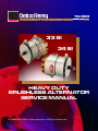
33 SI
34 SI
HEAVY DUTY
BRUSHLESS ALTERNATOR
SERVICE MANUAL
©1998 Delco Remy International Inc. All Rights Reserved.
PAGE
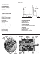
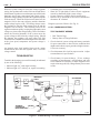
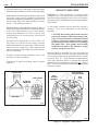
33/34 SI ALTERNATOR
FEATURES
SPECIFICATIONS:
MAXIMUM SPEED:
Continuous: 10,000 rpm
Intermittent: 12,000 rpm
198.0 mm
ROTATION:
Clockwise
Counterclockwise
TEMPERATURE LIMITS:
-40°F or -40°C Ambient
+200°F or +93°C Ambient
262.4 mm
POLARITY:
33-6210
Negative Ground Standard
Insulated Models Available
MOUNTING:
Brushless Construction
SAEJ180 Standard
Stationary Field Coil
No Brushes or Slip Rings
WEIGHT:
33 SI 24.5 pounds or 11.1kg
34 SI 25.4 pounds or 11.5g
Corrosion Protection
Built-In Voltage Regulator
Applications
Special Environmental Protection Coating
Solid-State Integrated Circuit
Flat Temperature-Compensated
Low Parasitic Draw
Low Turn-On Speed
Improved RFI Suppression
Load Dump Protection
Relay
Terminal
Line-Haul Diesel Trucks
Large Commercial Diesel Engines
Harsh Environments
Heavy Belt Loads and Vibrations
Indicator Light
Terminal
Heavy-Duty
Roller Bearing
Output
Terminal
Integrated
Circuit
Regulator
Stationary
Field Coil
(Brushless)
Die Cast
Aluminum
Fan
Heavy-Duty
Ball Bearing
Rectifier
Bridge
Stator
33-6208
33/34 SI ALTERNATOR
PAGE
1
PRODUCT INFORMATION AND SERVICE MANUAL
33/34 SI HEAVY DUTY BRUSHLESS ALTERNATOR
CONTENTS
Introduction ............................................................... 1
Features ..................................................................... 2
Operating Principles .................................................. 3
Troubleshooting ........................................................ 4
A. All Charging Systems .................................... 4
B. Systems with Indicator Light ......................... 5
C. Systems without Indicator Light .................... 5
D. R Terminal Accessory Problems ................... 6
E. No Output ....................................................... 6
F. Rated Output Check ....................................... 7
Alternator Unit Repair ............................................... 9
Disassembly and Bench Checks ......................... 9
Final Disassembly ............................................... 12
Alternator Assembly ................................................. 14
DE Frame and Rotor ........................................... 14
Rectifier End Housing and Components ............ 14
Final Alternator Assembly ................................. 18
Alternator Bench Test ......................................... 20
Alternator Installation ............................................... 21
Alternator Specifications ........................................... 25
Service Parts .............................................................. 26
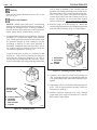
The 34 SI is identical to the 33 SI except for the stabilizing
lug (4th lug) on top of the rectifier end frame and the
ground screw is located on the right side of the rectifier end
housing. The stabilizing lug provides superior vibration
resistance on certain applications.
The 33/34 SI alternator may be operated in either clockwise
or counterclockwise directions (external fan may require
changing to reverse rotation) at continuous speeds of up to
10,000 alternator rpm. Intermittent speeds of up to 12,000
alternator rpm are also acceptable. The ambient temperature
range for proper operation is -34°C to +93°C (-30°F to
+200°F).
33-6211
Figure 1. 33 SI Alternator
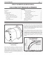
INTRODUCTION
The 33/34 SI series alternator is a brushless, heavy-duty
integral charging system with built-in diode rectifier and
voltage regulator, producing DC current for battery
electrical systems. The 33/34 SI series is designed for use
on large and mid-range diesel and gasoline engines in over
the-road service, as well as for off-road, agricultural, and
construction equipment.
33-6212
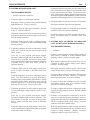
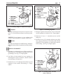
Figure 2. Typical Output vs. Alternator RPM
PAGE
33/34 SI ALTERNATOR
2
The solid state, integrated circuit voltage regulator built
into the 33/34 SI alternator limits system voltage by
switching the ground circuit for the field on and off. When
the ground circuit is on, field current passes from a diode
trio through the stationary field coil. Nominal regulated
voltages of 13.8, 14.0, and 14.2 volts are available for 12
volt systems, and 27.5 volts for 24-volt systems.
For 12-volt systems, output ratings of 110 and 135 amperes
are available. For 24-volt systems, an output rating of 100
amperes is available. Refer to Figure 2 for graphs of
typical outputs over a range of alternator speeds. For
output ratings of specific 33/34 SI models refer to DRA
model specifications.
FEATURES
POS
R I
BATTERY
ALTERNATOR
33-6214
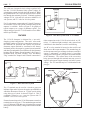
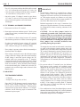
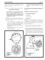
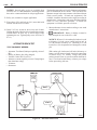
Figure 4. One-Wire System with "I" Terminal
The 33/34 SI alternator is designed for a “one-wire”
charging system configuration. “One-wire” refers to the
minimum number of lead wire connections necessary at
the alternator for operation and requires only that the
alternator output terminal be connected to the battery
insulated (positive for a negative-ground system) terminal
and that a ground path be provided between the alternator
housing and the battery ground terminal. (See Figure 3)
(Insulated units will have a battery "Pos" and battery
"Neg" terminal for "Output" and "Ground" connections.)
POS
OPTIONS
Other connections to the 33/34 SI series include an “R”
(relay), “I” (indicator light) terminal, and a ground lead
connection to the alternator’s rectifier end housing.
An “R” or relay terminal is located on the rectifier end
frame next to the output terminal. This terminal may be
used to operate some types of charge indicators, an ADLO
system, a tachometer, or similar device by providing
voltage pulses at a frequency of 8 pulses for each revolution
of the alternator. The current draw of the accessories
being powered through this terminal must not exceed 4
amperes and operate at approximately one half of system
voltage. The “R” terminal may be 10-24 threaded or the
pin type.
R I
"R" TERMINAL
GROUND
"I" TERMINAL
ALTERNATOR
OUTPUT
TERMINAL
(B+)
BATTERY
I
33-6213
Figure 3. Basic One-Wire System
The “I” terminal may be used in a circuit to power an
indicator light and/or to lower the engine speed (RPM) at
which the alternator will turn on. Typical system wiring
using this type of circuit is shown in Figure 4. This is
commonly referred to as a “one-wire system with "I"
terminal” or as a “two-wire system.
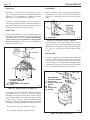
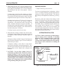
External connections to the 33/34 SI alternator are made to
terminals shown in Figure 5. The standard output terminal
is a 1/4"-28 thread. With this type of terminal, the exposed
metal parts will have battery voltage when connected to the
battery.
R
POS
34 SI
GROUND
33-6215
Figure 5. 33/34 SI Electrical Terminals
33/34 SI ALTERNATOR
PAGE
The “I” terminal is connected internally to the field circuit.
An indicator light connected in series with this terminal
will glow whenever there is a voltage difference between
the “positive” side of the field circuit and the system
voltage at other side of the indicator light. During normal
alternator operation, the light will be off since the diode
trio output voltage equals the system voltage. Current
passed through the field winding during engine start-up,
results in a lower alternator turn-on speed. A diode or
resistor may be used instead of a light bulb if no indicator
light is needed. (See Fig. 4) Up to 1 ampere of current may
be passed through this circuit to aid in alternator turn-on.
An “I” terminal is normally a threaded stud type with a 1024 thread.
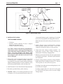
A threaded 1/4" hole (with screw and lockwasher assembly)
in the rectifier end housing is provided to connect a ground
lead if used; otherwise, the ground path is through the
mounting hardware and brackets to the engine. On
replacement units, a paper tag is present identifying the
“ground screw”; remove and discard the tag. The screw
and lockwasher assembly should be installed in the housing
regardless of whether a ground lead is connected, to
prevent entry of dirt and water.
All electronic parts of the alternator are specially coated
for environmental protection against moisture and dirt,
and the alternator is “inside cooled” by air drawn through
inlets in the rectifier end frame and exiting from the drive
end frame behind the fan.
REGULATOR
OPERATING PRINCIPLES
An alternator is a voltage-creating machine. The voltage
regulator limits the maximum voltage that the alternator
will produce at the output terminal by controlling the
magnetic field present in the stationary field. The output
voltage, induced in the stator and rectified by the diodes,
allows current to flow to satisfy the electrical loads placed
on the system, up to a maximum current that is characteristic
of the alternator design.
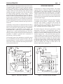
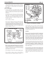
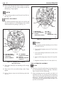
Schematics of the alternator circuitry are shown in Figure
6 (standard unit) and Figure 7 (insulated unit). With the
alternator rotor turning, a magnetic field around the
stationary field coil is conducted by the rotor poles to
induce voltages in the stator windings. The faster the rotor
turns, the higher the induced voltage will be.
The initial voltages at start-up are generated by residual
magnetism in the rotor. On applications with an “I”
terminal in use, this magnetism will be boosted by a small
amount of current flowing through the field from the
indicator light circuit. As speed and output increase,
voltage available at the diode trio becomes sufficient to
supply field current for normal operation. When the output
voltage exceeds the battery voltage, the alternator begins
to drive the system voltage. If the wiring system includes
an indicator light, the presence of system voltage at the
diode trio equalizes the voltage on both sides of the
indicator light and the light goes out.
I
CAPACITOR
FIELD
COIL
3
FIELD
COIL
REGULATOR
DIODE TRIO
B+
DIODE TRIO
CAPACITOR
I
B+
R
STATOR
STATOR
R
GND
RECTIFIER BRIDGE
RECTIFIER BRIDGE
33-6216
Figure 6. Alternator Schematic
B33-6217
Figure 7. Insulated Model Schematic
PAGE
33/34 SI ALTERNATOR
4
While the system voltage is below the voltage regulator
setting, the regulator turns on the field current and allows
the alternator to produce as much output as possible for the
alternator speed (rpm), temperature and system voltage.
When the voltage setting is reached, the regulator turns the
field current off. When the field current is turned off, the
magnetic field in the rotor collapses and the alternator
output voltage begins to fall. The falling voltage causes
the regulator to turn the field current back on and the
magnetic field to rebuild. This switching action of the
regulator continues rapidly, keeping the output and system
voltage very close to the voltage setting. This will continue
unless the electrical demands of the system cause the
system voltage to fall below the voltage setting. Should
this happen, the regulator will again allow full field
current to flow so that the maximum output of the alternator
at the given speed, temperature and system voltage is
realized.
An internal sense lead installed between the output
terminal/diode heat sink and regulator stud, is used for
voltage control.
• Undercharged or overcharged battery.
• Short life of light bulbs or other electric equipment
caused by abnormally high system voltage.
• System voltmeter readings outside normal range.
• Incorrect or no operation of accessories connected to
alternator “R” terminal.
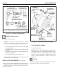
Diagnose system as follows: (See Fig. 8)
A. ALL CHARGING SYSTEMS TEST EQUIPMENT NEEDED:
• Belt Tension Gage
• Battery State-of-Charge Indicator
1. Check electrical system wiring and battery terminals
for poor connections or other obvious conditions that
might result in shorts, opens, grounds, or high resistance.
Correct as necessary.
2. Check alternator drive belt for proper tension. Adjust
to manufacturer's specifications.
TROUBLESHOOTING
Trouble in the charging system will normally be indicated
by one of the following:
• Indicator light “on” with engine running.
• Indicator light “off” with key on, engine not running.
3. Check battery for state-of-charge. If low, recharge
according to manufacturer’s specifications and load
test to establish serviceability. Further diagnostic tests
require a known good, fully-charged battery for accurate
results.
INDICATOR
LIGHT
KEY
SWITCH
VOLTMETER
INDICATOR
LIGHT
CIRCUIT
FUSE
BLOCK
D2
D3,E2
OUTPUT
TERMINAL
R I
POS
ALTERNATOR
INDICATOR
LIGHT ("I")
CONNECTOR
TERMINAL
B2, B3
CONNECTOR
(DISCONNECTED)
E1
BATTERY
FUSE
33-6218
Figure 8. Troubleshooting a 33/34 SI System
33/34 SI ALTERNATOR
B. SYSTEMS WITH INDICATOR LIGHT TEST EQUIPMENT NEEDED:
• Jumper Lead with 5-Amp Fuse
PAGE
5
- If indicator light does not come on with jumper lead in
place, locate and correct open circuit in indicator light
circuit between battery and light. Circuit fuse may be
open. (With engine running, light is being powered by
alternator and grounded through other circuits connected
in parallel to indicator light circuit.) Correct as necessary.
1. If indicator light is on with engine running:
4. If indicator light is on with key switch in “off” position:
Stop engine. Turn key switch to “run” position. Indicator
light should be on. If not, go to Step 3.
Disconnect indicator light circuit at alternator.
Disconnect indicator light lead at alternator. This will
be the “I” terminal connector.
- If indicator light remains on, locate and correct shorted
condition between the light and alternator.
If indicator light remains on, locate and correct shorted
or grounded condition in indicator light circuit between
the light and the alternator.
- If indicator light goes out, diode is shorted in rectifier.
Locate and replace diode as described under Unit
Repair.
If indicator light goes out, light is working properly.
Proceed to “C.” for check of system with indicator light
working properly.
C. SYSTEMS WITH VOLTMETER, NO INDICATOR
LIGHT, OR WITH LIGHT WORKING PROPERLY TEST EQUIPMENT NEEDED:
2. If indicator light does not come on with the key switch
in the “run” position with the engine stopped (“bulb
check” mode):
Leave key in “run” position with engine stopped.
Disconnect indicator light lead from alternator. This
will be at the “I” terminal. Use fused (5-amp) jumper
lead to ground indicator lamp circuit in harness connector
to ground screw or other clean metal ground on
alternator housing.
- If indicator light comes on with jumper lead in place,
repair or replace alternator as described under Unit
Repair.
- If indicator light does not come on with jumper lead in
place, verify that alternator is properly grounded by
touching jumper lead to another ground source. If lamp
still does not light, locate and correct open circuit in
indicator light circuit. Circuit fuse may be open or light
bulb may be burned out. Correct as necessary.
• Voltmeter
1. If battery is undercharged, indicator light remains on
while vehicle is running, or system voltmeter shows
operating voltage is below acceptable range:
With engine stopped and all electrical loads off, use
voltmeter to check system voltage across battery
terminals. Record voltage.
Start engine and run at moderate speed. Check system
voltage across battery terminals with engine running.
- If voltage reading at battery terminals is different from
reading showing at system voltmeter (if equipped),
locate and correct cause of incorrect reading.
- If voltage is lower than reading previously recorded
with engine stopped, there is no alternator output.
Proceed to section on No Output.
3. If indicator light comes on while engine is running, but
is not on with engine stopped and key switch in “run”
position:
- If voltage is higher than previous reading with engine
stopped, alternator output is present. Proceed to Rated
Output Check.
Leave key in “run” position with engine stopped.
Disconnect indicator light lead from alternator. This
will be at the “I” terminal. Use fused (5-amp) jumper
lead to ground indicator lamp circuit to alternator
housing.
2. If battery is overcharged (as evidenced by excessive
water use or electrolyte spewing from battery vents), or
light bulbs or other electrical equipment have shortened
life due to suspected high system voltage, or system
voltmeter reads above normal range:
- If indicator light comes on with jumper lead in place,
replace internal indicator light lead assembly or regulator
as described under Unit Repair.
With fully charged battery, engine running at moderate
speed and all electrical loads off, use voltmeter to check
voltage at battery terminals. (Battery electrolyte
temperature must be below 120°F (49°C).)
PAGE
6
For a 12-volt system, readings should be stable, around
13.5 - 14.5 volts and in no case go above 15.5 volts. For
a 24-volt system, readings should be stable, around 27
- 28 volts and in no case go above 31 volts.
- One-wire system: If voltage is erratic or goes above
15.5 volts (31 volts on 24-volt system), check internal
sense circuit and regulator as described under
Unit Repair.
D. "R" TERMINAL ACCESSORY PROBLEMS
1. Disconnect lead from “R” terminal.
2. Start engine and run at moderate speed. Check system
voltage across battery terminals with engine running.
Record voltage.
3. Use voltmeter to check voltage between “R” terminal
and alternator ground screw or other clean metal ground.
- If voltage is near half of system voltage, “R” terminal
output is O.K. Note that this is a pulsating signal, so
some voltmeters may give an unsteady reading.
- If no voltage is present, replace diode trio assembly as
described under Unit Repair.
- If the voltage is nearly the same as the alternator output
voltage, check the voltage at the other small terminal.
If that voltage is near half system voltage, the "R"
terminal leads were connected to the "I" terminal.
Connect them to the "R" (half voltage) terminal. If both
terminals are near alternator output voltage, replace the
diode trio assembly, unless internally both terminals
are wired to the same place. In that case, rewire the "R"
terminal to the rectifier bridge stud as shown in Unit
Repair section.
E. NO OUTPUT
TEST EQUIPMENT NEEDED:
• Voltmeter
• Jumper Lead (18 ga. min; no fuse)
Note that 33/34 SI alternators must be connected to a
battery for the voltage sensing circuit to allow initial
turn on (refer to section on Features). When properly
connected and system checks indicate a “no output”
condition, use the following steps to determine if the
alternator requires repair:
33/34 SI ALTERNATOR
IMPORTANT
1. For alternators without an “I” terminal in use, battery
positive voltage at the output terminal and residual
magnetism in rotor are necessary for alternator to turn
on. With engine stopped, use voltmeter to verify that
battery voltage is present in cable at output terminal. If
not, locate and correct cause of voltage loss.
Residual magnetism in the rotor is sometimes lost
during servicing of the alternator. The rotor can normally
be remagnetized without removing alternator from
application.
CAUTION: Do not allow jumper lead to be
accidentally grounded while connected to battery
terminal. If the free end of this lead is accidentally
touched to the alternator housing or other grounded
areas, the jumper lead may quickly get hot enough
to cause a skin burn or to damage the jumper lead.
Keep jumper lead carefully insulated from
grounding during this procedure.
To remagnetize rotor, make sure the normal connections
are made to the alternator output terminal and to the
ground circuit. Disconnect the wiring harness from the
“R” terminal. Momentarily connect a jumper lead from
battery positive to the alternator “R” (or unused “I”)
terminal. (See Fig. 42) This will cause field current to
momentarily flow through the field windings in the
proper direction and restore magnetism. Reconnect
wiring harness to “R” terminal, then recheck alternator
for output.
2. For systems with an “I” terminal in use, the indicator
light current at this terminal will establish normal
magnetism at each engine start-up. Such systems may
depend on this current to help ensure a low turn-on
speed of the alternator. With engine stopped and key
switch in “run” position, use voltmeter to check for
voltage present at this terminal. With “I” terminal
connected and indicator lamp on, voltage will be less
than battery voltage. If necessary, disconnect wiring at
“I” terminal to make this check, check for battery
voltage in harness wire. If voltage is present, proceed
to Step 3. If no voltage is present, check “I” terminal
circuit for cause of voltage loss (bulb may be burned
out). Correct as necessary.
3. If no conditions have been found that might prevent the
alternator from turning on (Step 1 or 2), remove alternator
from engine in accordance with engine manufacturer’s
instructions and proceed to Unit Repair.
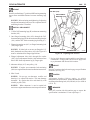
33/34 SI ALTERNATOR
PAGE
CLAMP-ON
AMMETER
7
CARBON
PILE
A
F9
POS
R I
F6,F8
BATTERY
ALTERNATOR
V
F5
VOLTMETER
33-6219
Figure 9. Rated Output Check
F. RATED OUTPUT CHECK
volt potential in battery pack. Attaching a 12-volt load
test to a 24-volt potential will damage the load test.
TEST EQUIPMENT NEEDED:
• Voltmeter
• Ammeter (current capability at least 15 amperes
higher than alternator rating)
• Variable Carbon Pile Load Test
CAUTION: Failure to disconnect grounded battery
cable at battery before removing or attaching battery
cable at alternator output terminal may result in an
injury. If a tool is shorted to the battery cable
connector at the output terminal, the tool can quickly
heat enough to cause a skin burn or the tool or cable
may be damaged.
1. Refer to Fig. 9 for test equipment hookups as described
in following steps. If inductive pickup (“clamp on”)
type ammeter is used, place current clamp on alternator
output lead and skip to Step 4. If series ammeter is used,
disconnect grounded battery cable at battery first.
2. Install ammeter in series with alternator output terminal.
3. Reconnect grounded battery cable at battery.
4. NOTICE: When a 12-volt carbon pile load test is used
to diagnose a 24-volt system attach load test only to 12-
With load turned off, attach carbon pile load test across
battery.
5. Attach voltmeter lead to grounded battery terminal,
observing proper polarity for system. Leave other
voltmeter lead open for checks at various points.
6. Check and record voltage at battery terminal. For
multi-battery systems, check voltage of battery set
connected as if in battery charging mode.
7. With all system electrical loads off, start engine and run
at moderate speed (rpm). Alternator speed should be
near 5,000 rpm.
8. Recheck voltage at battery terminal. Voltage should be
higher than previous reading, but below 15.5 volts on
12-volt system (31 volts on 24 volt system).
- If reading is lower than previous reading (Step 6), refer
to section on No Output.
- If reading is higher than 15.5 volts on 12-volt system
(31 volts on 24-volt system), refer to section on High
Voltage Output.
PAGE
33/34 SI ALTERNATOR
8
9. Turn carbon pile load on and adjust to obtain maximum
alternator output on ammeter. Record maximum output.
With alternator still running at maximum output, check
and record voltage drop in ground circuit between
alternator housing and grounded battery terminal. Then
check voltage drop from output terminal to battery
positive. Turn carbon pile load off.
Maximum ampere output should be within 15 amps of
output rating stamped on alternator identification plate,
or as listed in Specifications section of this manual.
Voltage drop should be 0.25 volts or less for each
voltage drop test on 12-volt system (0.5 volts or less on
24-volt system).
- If ground circuit voltage drop is over 0.25 volts on 12volt system (0.5 volts on 24-volt system), clean and
tighten all ground circuit connections. If this does not
correct excessive voltage drop, check ground circuit
cables for improper sizing or high resistance conditions.
Correct as necessary.
- If within 15 amps of rating, alternator is good. Look
elsewhere for cause of problem.
- If more than 15 amps below rating, repair or replace
alternator.
REGULATOR "QUICK CHECK"
NOTICE: On some alternators on certain engine
configurations, a 1.5µf capacitor has been installed to the
output terminal and attached with a cover screw. Remove
the capacitor (DRA 1985444) before performing "Regulator
Quick Check."
A “No Output” condition may be caused by a defective
regulator. This can be determined by the following
procedure.
CAUTION: Do not allow jumper lead or probe to
touch strap or battery while connected to ground.
If the free end of this lead is accidentally touched
to battery voltage, the jumper lead may quickly
get hot enough to cause a skin burn or to damage
the jumper lead. Keep jumper lead carefully
insulated from battery and alternator voltage
surfaces during this procedure.
Install and hook up alternator (Fig. 10) in test bench (at
least 5 hp) and remove rectifier cover plate. Attach one end
of a test lead to alternator ground and the other to a sharp
test probe (Fig. 11). Spin alternator at approximately
2,000 rpm and touch probe to insulated field ground
terminal under the insulation at regulator (not on screw
head). Be sure probe touches metal terminal through the
protective coating!
TOUCH UNDER
THE INSULATION
CARBON PILE
TEST PROBE
FIELD
GROUND
TERMINAL
TEST
LEAD
CLAMP ON
AMMETER
BATTERY
ALTERNATOR
33-6221
Figure 10. Test Bench Schematic
33-6220
Figure 11. Regulator “Quick Check”
33/34 SI ALTERNATOR
9
PAGE
If ammeter shows 20 amps or more and drops to zero when
probe is removed, replace the regulator and test field coil
for shorts or grounds.
If no output, remove alternator and make bench checks.
ALTERNATOR UNIT REPAIR
CAUTION: Disconnect grounded cable at battery
before removing or attaching battery cable at
alternator output terminal. Otherwise, a tool
shorted to the battery cable at the output terminal
can quickly heat enough to cause a skin burn or
damage the tool or cable.
NOTICE: Always reinstall fasteners at original location.
If necessary to replace fasteners, use only correct part
number or equivalent.
• If correct part number is not available, use only
equal size and strength. For alternator internal
fasteners, refer to Delco Remy Standard Hardware
Fasteners section in Service Parts Catalog.
• Fasteners that are NOT to be reused will be noted
in procedure.
• Fasteners requiring thread locking compound will
be noted in procedure.
• Use specified torque values when shown.
POS
R
CAUTION: Using or replacing fasteners in any
other manner could result in part or system
damage.
If diagnosis determines that alternator repair is needed,
remove alternator from engine according to manufacturer’s
instructions.
DISASSEMBLY AND BENCH CHECKS
TEST EQUIPMENT NEEDED:
• Multimeter
• Regulator Tester
ALTERNATOR
NOTICE: On some alternators on certain engine
configurations, a 1.5µf capacitor has been installed to the
output terminal and attached with a cover screw. Remove
the capacitor (DRA 1985444) before performing
"Regulatror Quick Check."
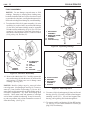
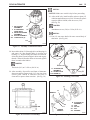
1. Remove screws (216) and rectifier end plate (15) to
expose electronics compartment. (See Fig. 12)
2. Inspect electronics compartment for contamination, for
shorted or grounded wires, and for loose connections.
If contamination is present, clean and dry compartment
before proceeding. The protective coating on all
electronic components is a good insulator and must be
scraped off to get a good contact for test equipment
probes.
I
OHMMETER - USE WITHOUT BATTERY
VOLTMETER - USE WITH BATTERY
15
217
A
216
6
1
224
CLAMP ON
AMMETER
1. RECTIFIER END
HOUSING
ASSEMBLY
15. COVER PLATE
216. SCREW
Figure 12. Electronics Compartment
6. REGULATOR
217. SCREW
224. SCREW
33-6223
33-6222
Figure 13 Checking Field Coil Resistance
PAGE
33/34 SI ALTERNATOR
10
FIELD COIL
CAPACITOR
3. Disconnect 2 field leads (A) from regulator (6) (See
Fig. 13), by removing 2 insulated regulator attachment
screws (217). Use ohmmeter (or voltmeter, ammeter
and battery) to check resistance of field coil.
Compare to Field Check ohms (or volts and amps) in
Specifications at the end of this manual or from Service
Specification Bulletin. If outside specifications, replace
field coil as described later in this manual.
5. Remove capacitor (12) by removing the remaining two
attachment screws (224) and screw (226) sliding out
capacitor. (A sharp tool may be used to break varnish
seal.)
T
OHMMETER
12
DIODE TRIO
F
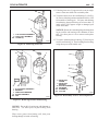
4. To check the diode trio (7), remove it from the electronics
compartment by detaching the 3 nuts (218), stator leads
(B) and attaching screw (217). Note that the insulating
washer on the screw is assembled over the top of the
diode trio connector. Discard screw if insulation is
fractured during removal.
OHMMETER
217
12. CAPACITOR
33-6225
Figure 15. Electrical Check of Capacitor
Using continuity check mode (diode check mode on
digital meter), check for a shorted capacitor by touching
ohmmeter leads to capacitor lead (F) and grounding tab
(T). (See Fig. 15) This check should show an open
circuit.
218 (3)
REGULATOR
6. To remove regulator (6) for testing, remove sense lead
nut (218), bridge to regulator stud connector (219) and
2 screws (217) if not removed previously and screw
(224). Disconnect “I” terminal sense lead strap to allow
regulator removal. (See Fig. 16) Note: Discard insulated
screw if insulation is fractured during removal.
7
1
B
217
1. RECTIFIER END
HOUSING ASSEMBLY
7. DIODE TRIO
217. SCREW (INSULATED, SHORT)
218. NUTS
33-6224
Figure 14. Electrical Check of Diode Trio
Use ohmmeter or diode check function on multimeter to
check diode trio (7). (See Fig. 14) Place negative
ohmmeter lead on the regulator strap and the positive
lead to check continuity to each of the three rectifier
bridge straps. All three readings should indicate
continuity. Reverse the ohmmeter leads and perform
checks again. Reading should all indicate open circuits.
224
1. RECTIFIER END
HOUSING ASSEMBLY
6. REGULATOR
217. SCREW (2 INSULATED,
SHORT)
218. NUT
219. CONNECTOR
224. SCREW
218
219
6
1
– If all readings are proper, diode trio is good.
– If any reading is wrong, replace diode trio.
33-6227
Figure 16. Removing Regulator
33/34 SI ALTERNATOR
PAGE
Check regulator on approved tester for SI type regulators.
If regulator tests “good”, return it to service. If it tests
“bad”, replace it. Install regulator as described later in
this section.
199
198
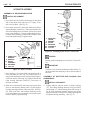
7. Use the ohmmeter or (for digital meters) the diode
check function of the multimeter to check the rectifier
bridge (8). Bridge may be checked in place in the RE
housing (1).
Check 6 diodes as follows:
Place negative ohmmeter lead on grounded heat sink.
Touch positive ohmmeter lead firmly to metal diode
clips that surround each of the 3 threaded studs. All 3
readings should be the same, and indicate open circuits.
Switch leads and repeat. All 3 new readings should
indicate continuity. (Fig. 17)
POSITIVE HEAT SINK SIDE
193
OHMMETER
RECTIFIER BRIDGE
All terminals must be disconnected from the threaded
phase studs. “R” terminal and output terminal straps
(198 &186) may be raised approximately one inch (2.5
cm) above rectifier for removal of diode trio (7) or
rectifier bridge (8).
11
12
226
224
8.
12.
193.
198.
199.
B.
RECTIFIER BRIDGE
CAPACITOR
RELAY STUD
RELAY STRAP
NUT
8
218
226. SCREW
(INSULATED LONG)
218. NUT (3)
224. SCREW
33-6228
Figure 18. Checking Stator Windings
remove bridge, remove nut (218), nut (199) and relay
strap (198) from regulator stud (193), two bridge
attaching screws (226), and insulated capacitor attaching
screw (224). Lift capacitor (12) and rectifier bridge (8)
from SRE housing (Fig. 18).
STATOR
NEGATIVE HEAT
SINK SIDE
8
OHMMETER
8. RECTIFIER BRIDGE
33-6226
Figure 17. Electrical Check of Rectifier Bridge
Repeat checks using insulated (positive) heat sink in
place of grounded heat sink. With negative ohmmeter
lead on insulated heat sink, all 3 readings should indicate
continuity. Switch leads and repeat. All 3 new readings
should indicate open circuits.
– If all readings are correct, the rectifier bridge is good.
– If any reading is wrong, an open or shorted diode is
indicated and rectifier bridge should be replaced. To
8. Disconnect the 3 stator phase leads (B) from the diode
bridge studs by removing 3 nuts (218). Use continuity
check function of ohmmeter to check stator windings.
(See Fig. 18) Place one meter lead on one of the stator
phase lead connectors and check for continuity to each
of the other two stator leads. There should be continuity
to both. If not, one or more of the stator coils is open;
replace the stator as described later in this section.
To check for grounds, again touch one meter lead to one
of the stator phase leads, and touch the other meter lead
to clean metal ground on the alternator housing. There
should not be continuity. If there is continuity, the
stator is grounded and should be replaced as described
later in this section.
It is not possible to detect shorted stator windings with
ordinary shop equipment. However, if all other electrical
checks are normal and the alternator has exhibited low
output, shorted stator windings may be the cause. In
such cases, replace the stator as described later in this
section.
PAGE
12
33/34 SI ALTERNATOR
FINAL DISASSEMBLY
NOTICE: Do not damage exposed stator or field
windings. Bumping or scraping these windings may
break the insulation and leave a place for a short circuit
or ground to develop later, causing the alternator to fail.
Protect the windings from damage by careful handling.
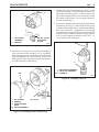
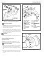
9. To replace the field coil (9), stator assembly (11), rotor
assembly (10), or drive end (5) or rectifier end bearings
(2), the drive end frame assembly must be separated
from the rectifier end housing. (Fig. 19) Use 5/16" hex
wrench or 5/16" hex drive, in the end of the shaft, to
hold while removing shaft nut (211). Remove washer
(212), pulley (14), and fan (13).
G
1
11
4
1. RE HOUSING
ASSEMBLY
4. DRIVE END FRAME
ASSEMBLY
11. STATOR
213
213. THRU-BOLTS (4)
33-6230
13
Figure 20. Separating Housings
14
WRENCH
1
212
211
TORQUE
WRENCH
G. ALTERNATOR
ASSEMBLY
13. FAN
14. PULLEY
211. NUT
212. WASHER
B
33-6229
C
Figure 19. Alternator Disassembly
10. Remove the 4 thru bolts (213). Carefully separate the
drive end housing (4) from the stator (11) and rectifier
end housing (1), taking care not to damage stator
windings. (See Fig. 20)
NOTICE: Rectifier bridge must be removed before
removing stator. (See Paragraph 7 and Fig. 18) To remove
stator (11) from rectifier end housing (1), be sure all 3
stator leads are disconnected from diode bridge studs in
electronics compartment. Pry stator and housing apart
carefully. Guide stator leads and grommet (C) through
well as stator is pulled from housing. It may be necessary
to push on grommet with a blunt instrument to unseat it
from the housing. (See Fig. 21)
B. STATOR LEADS
C. GROMMET
1. RE HOUSING
ASSEMBLY
11. STATOR
33-6231
Figure 21. Removing Stator
11. To remove field coil and support (9) from rectifier end
housing, (See Fig. 22) remove 4 field coil and support
attaching screws (221). Lift coil and support from
housing, while guiding field leads through hole.
12. To remove rectifier end bearing (2) from RE housing
(1), (See Fig. 23) use small screwdriver at slot to pry
plug (222) from housing.
33/34 SI ALTERNATOR
PAGE
13. If bearing inner race (3) appears to be worn or rough,
remove from rotor shaft with a suitable puller.
221
14. To replace rotor (10) or drive end bearing (5), (See Fig.
24) remove 4 bearing retainer attachment screws (214)
from outside of housing (4). Lift rotor with bearing
from housing, then pull bearing off of rotor shaft. If
inside collar (215) appears rough or damaged, pull
collar from shaft.
1
9
NOTICE: Do not drive mounting hinge bushing from
lug on rectifier end housing with a hammer or other
tool. Use arbor press or vise to remove and replace
bushing.
1. R.E. HOUSING ASSEMBLY
9. FIELD COIL ASSEMBLY
221. SCREW (4)
33-6232
Figure 22. Removing Field Coil
3
13
15. To remove mounting hinge bushing (17) from lug on
rectifier end housing (1), Press bushing from housing
using arbor press with suitable tool.
222
1
10
10
16
215
5
4
2
3
1.
2.
3.
10.
222.
4. DRIVE END
FRAME
5. DRIVE END
BEARING
10. ROTOR ASSEMBLY
16. RETAINER
214. SCREWS (4)
215. COLLAR
2
R.E. HOUSING ASSEMBLY
BEARING
INNER RACE BEARING
ROTOR ASSEMBLY
CAP
214
33-6234
Figure 24. Disassembly of Drive End Components
33-6233
Figure 23. Removing Rectifier End Bearing
NOTICE: Do not drive bearing out with hammer or
other tool. Use arbor press to push bearing from
housing.
Wipe excess grease from bearing well, then press
bearing through to inside of housing.
PAGE
33/34 SI ALTERNATOR
14
ALTERNATOR ASSEMBLY
ASSEMBLY OF DE FRAME AND ROTOR
10
INSTALL OR CONNECT
1. Press inner race for rectifier end bearing (3) onto short
end of rotor shaft. Stop when race is 3.7 mm (.15 in.)
above end of shaft. (See Fig. 25)
2. Press inside collar (215) onto rotor shaft until collar is
against shoulder on rotor (10). Place retainer plate (16)
onto collar (flanged side of retainer will face away from
rotor, toward bearing). Using open tube that bears only
on inner race of bearing, press new DE bearing (5) onto
rotor shaft until bearing is against collar.
16
5
215
10
16
215
5
4
4. DRIVE END
FRAME
5. BEARING
10. ROTOR
16. RETAINER
214. SCREWS (4)
215. COLLAR
214
33-6234
Figure 26. Installing Rotor in Drive End Frame
3
3
3. INNER RACE
BEARING
5. BEARING
10. ROTOR
ASSEMBLY
16. RETAINER
215. COLLAR
TIGHTEN
3.7MM
(0.15 in.)
Bearing retainer attaching screws (214) to 5 N.m (45 lb.
in.).
10
33-6236
Figure 25. Rotor Assembly
IMPORTANT
To allow access for later installation of thru bolts (213),
do not assemble fan and pulley to drive end assembly at
this time.
3. Insert bearing (5) (on rotor shaft) into bearing well in
drive end frame (4). (See Fig. 26) Bearing will be a
snug fit, but should slip in easily when properly aligned.
Lubricate outside of bearing very lightly with ball and
roller bearing lubricant (1948791) if necessary to
facilitate assembly.
ASSEMBLY OF RECTIFIER END HOUSING AND
COMPONENTS
4. Hold drive end assembly with long end of rotor shaft
down so that bearing retainer plate (16) falls against
housing, then align retainer with screw holes. (See Fig.
26) Start each of the four retainer attaching screws
(214), then tighten screws gradually in sequence to pull
retainer squarely against bearing.
5. Lightly lubricate outside surface of hinge bushing
(17). Press hinge bushing into hole in lug on rectifier
end housing (1). Install bushing flush with inside of
lug to allow maximum distance between two hinge
lugs for mounting. Final position of hinge bushing will
be adjusted during mounting. (See Fig. 27)
INSTALL OR CONNECT
33/34 SI ALTERNATOR
PAGE
7. Add ball and roller bearing lubricant (1948791) until
cavity between plug (222) and bearing outer race (2) is
about half full, placing grease so that it touches the
edge of the bearing outer race in several places around
the outside of the bearing. Cover opening with tape to
prevent contamination.
17
1
17
INSTALL FLUSH
WITH INSIDE
OF LUG
1. RE HOUSING
ASSEMBLY
17. BUSHING
15
8. Turn leads so that they will be properly positioned after
installation. (See Fig. 29) Place field coil and support
(9) into rectifier end housing (1), guiding leads through
hole into electronics compartment and aligning
mounting holes in support with screw holes in rectifier
housing. Ensure leads do not touch housing. Install 4
field coil and support attachment screws (221). (3
screws used in early production)
33-6235
221
Figure 27. Installing Mounting Hinge Bushing
6. Position new bearing (2) into rectifier end housing (1)
with seal toward rotor assembly (10) as assembled.
Press bearing outer race into housing center hole until
flush with machined face inside housing. (See Fig. 28)
Push plug (222) into end of housing until outside edges
are flush with edge of RE housing.
1
9
222
1. RE HOUSING ASSEMBLY
9. FIELD COIL ASSEMBLY
221. SCREW (4)
REF
10
33-6232
Figure 29. Installing Field Coil
1
1
2
10
1. RE HOUSING
2. BEARING
3. INNER BEARING
RACE
10. ROTOR ASSEMBLY
3
2
222
222. PLUG
33-6237
Figure 28. Installing Rectifier End Bearing
PAGE
33/34 SI ALTERNATOR
16
TIGHTEN
Field coil and support attachment screws (217) to 6.2
N.m (55 lb. in.).
INSTALL OR CONNECT
NOTICE: Handle stator with care to avoid bending
windings or breaking varnish insulation on windings. If
windings are damaged before or during installation,
they may become shorted and cause reduced alternator
output. Stator must be installed before rectifier.
well as stator is installed (if not, carefully push on
grommet with a blunt instrument to seat it in the well).
The stator must be fully seated in housing at this time.
Note: If necessary, place wood blocks on opposite
corners of the stator frame and use arbor press (or tap
blocks with hammer) to seat stator frame against
rectifier end housing. Do not push against windings!
10. Rectifier bridge (8) to RE housing (1). Install one
rectifier bridge attaching screw (224) through grounded
heat sink into RE housing. (Fig. 31) Finger tighten.
224
9. Straighten stator leads (B) to ease installation. Lubricate
grommet (C) on stator leads lightly with petroleum
jelly. Welded junction connector on some stators must
be positioned straight up from windings to prevent
grounding to housing or rotor when alternator is
assembled. Straighten stator lead wires all the way to
the windings and insert through well in housing into
electronics compartment. (See Fig. 30)
Align thru-bolt holes in stator (11) with those in RE
housing (1). Push stator into housing far enough to
hold it in place, being sure grommet (C) on wires is
inserted into well in housing at the same time. Stator
lead wires should be stiff enough to push grommet into
8
REF
B
1
1. RE HOUSING
8. RECTIFIER
BRIDGE
224. SCREW
33-6238
1
Figure 31. Installing Rectifier Bridge
11. Capacitor (12) to holes in end of rectifier bridge (8)
(Fig. 32) Install ground screw (224) through capacitor
(12), grounded heat sink, and into RE housing. Finger
tighten.
B
WOOD BLOCKS
FOR SEATING
STATOR
12. Output strap (186) over insulated rectifier and capacitor
holes. (If new output terminal assembly, install per
instructions in package.)
C
11
13. Insulated capacitor attaching screw (226), through
output strap (186), capacitor connector (12), and into
RE housing. Finger tighten.
B. STATOR LEADS (3)
C. GROMMET
1. RECTIFIER
END HOUSING
11. STATOR
33-6231
Figure 30. Installing Stator
33/34 SI ALTERNATOR
17
PAGE
226
186
224
12
8
REF
B
A.
1.
6.
12.
217.
218.
219.
224.
220.
1
1. RECTIFIER
END HOUSING
8. RECTIFIER
BRIDGE
12. CAPACITOR
186. OUTPUT STRAP
224. SCREW
226. SCREW (INSULATED, LONG)
FIELD COIL LEAD
RE HOUSING
REGULATOR
CAPACITOR
SCREW
(INSULATED, SHORT)
NUT
CONNECTOR
SCREW
1
TERMINAL COVER
A
217
224
218
219
220
6
REF
B
33-6239
Figure 32. Installing Output Terminal and Capacitor
INSPECT
Regulator mounting area for presence of grease or dirt
(Fig. 33). Good electrical contact is necessary in this
area.
NOTICE: Do not immerse or wet regulator with
solvent. Internal damage to regulator could result.
CLEAN
Regulator mounting bosses in RE housing, metal base
plate and contact rings on regulator by wiping with dry
cloth.
33-6240
Figure 33. Installing Regulator
17. Bridge to regulator stud connector (219) over threaded
stud of regulator (6) with nut (218). Finger tighten.
18. Diode trio (7) on to 3 threaded studs on rectifier
bridge (8).
19. Insulated screw (217) through indicator strap (208)
hole, long leg of diode trio (7) and other field coil lead
terminal (A) into regulator (6) unused hole and into
R.E. housing. (See Fig. 34) Finger tighten.
INSTALL OR CONNECT
208
226
14. Regulator (6) with terminal cover (220) assembled to
RE housing (1) with regulator attaching screw (224)
(grounding). (See Fig. 33) Finger tighten.
15. One field coil lead terminal (A) over regulator (6)
mounting hole closest to terminal. (Ensure leads do
not touch edge of frame hole.)
16. Insulated screw (217) through lead terminal (A) and
regulator (6) into rectifier end housing (1). Finger
tighten.
217
A
7
1
A. FIELD COIL
LEAD TERMINAL
1. R.E. HOUSING
7. DIODE TRIO
208. INDICATOR
STRAP
217. SCREW
(INSULATED, SHORT)
226. SCREW (INSULATED, LONG)
Figure 34. Installing Diode Trio and
Sense Connector
REF
B
33-6241
33/34 SI ALTERNATOR
18
PAGE
20. Screw (226) through other hole in bridge to regulator
stud connector (219) into rectifier bridge (8) and into
RE housing. Finger tighten.
217
224
TIGHTEN
6
21. Two rectifier ground screws (224) to 4 N.m (35 lb. in.)
(See Fig. 35)
218
226
INSTALL OR CONNECT
22. "R" terminal connector strap (198) over rectifier stud
closest to capacitor (12). (If installing new "R" terminal
follow instruction in package.) (See Fig. 35)
226
218
8
198
218
19
218. NUT
6. REGULATOR
8. RECTIFIER BRIDGE 224. SCREW
226. SCREW
217. SCREW
(INSULATED, LONG)
(INSULATED, SHORT)
33-6243
218
Figure 36. Fastener Torques
TIGHTEN
REF
12
224
B
B.
8.
12.
19.
STATOR LEADS
RECTIFIER BRIDGE
CAPACITOR
RELAY TERMINAL
8
1. One regulator ground (mounting) screw (224) to
2.5 N.m (23 lb. in.)
224
2. Two insulated regulator screws (217) to 2.0 N.m
(20 lb. in.)
198. "R" TERMINAL
CONNECTOR STRAP
218. NUTS (3)
224. RECTIFIER GROUND
SCREW (2)
33-6242
Figure 35. Installing "R" Terminal
and Stator Leads
23. Three stator leads (B) over matching rectifier bridge
(8) studs.
24. Three nuts (218) on rectifier bridge studs. Finger
tighten.
25. Secure fasteners shown in the following order (See
Fig. 36)
3. Two rectifier bridge insulated screws (226) to 2.0
N.m (20 lb. in)
4. Three rectifier bridge nuts (218) to 2.5 N.m (23 lb.
in.)
5. Regulator stud nut (218) to 2.0 N.m (20 lb. in.)
FINAL ALTERNATOR ASSEMBLY
CLEAN
26. Inner race of rectifier end bearing (3) on rotor shaft to
prevent contamination of grease. (See Fig. 37) Remove
tape to expose rectifier end bearing.
27. Align mounting lugs and assemble two halves of
alternator (See Fig. 37), inserting rectifier end bearing
inner race (on rotor shaft) into bearing in rectifier end
housing (1). Seat drive end housing (4) at this time.
Using arbor press and appropriate block to apply even
pressure on end frames.
33/34 SI ALTERNATOR
PAGE
19
INSTALL
NOTICE: Make sure varnish is dry before proceeding.
1
30. After varish is dry, install rectifier end cover plate (15)
with four attachment screws (216). If removed, replace
capacitor (DRA 198544) with one screw (216).
(See Fig. 39)
3
11
1. RE HOUSING
ASSEMBLY
10
3. R.E. BEARING
INNER RACE
4. DRIVE END FRAME
ASSEMBLY
10. ROTOR ASSEMBLY
213. THRU-BOLTS (4)
TIGHTEN
4
Attachment screws (216) to 3 N.m (26 lb. in.).
INSTALL
31. Fan (13) onto rotor shaft with vanes toward body of
alternator. (See Fig. 40)
213
33-6230
216
Figure 37. Assembly of Alternator Halves
15
28. Insert 4 thru-bolts (213) through drive end housing (4)
and stator (11) into threaded holes in rectifier end
housing (1). Align housings and stator as needed to
allow thru-bolts to stand straight in holes and engage
threads. When all four thru-bolts are inserted, tighten
them in round-robin fashion.
CAPACITOR
TIGHTEN
216
Thru bolts (213) to 12.4 N.m (110 lb. in.)
29. After assembly, dip rectifier end frame of alternator
about one and one quarter inch (1¼") deep into clear
electric grade varnish or otherwise coat area of
electronics to protect from corrosion. (See Fig. 38)
216
G. ALTERNATOR
ASSEMBLY
15. COVER PLATE
216. SCREW (4)
G
33-6245
Figure 39. Installing Cover Plate
G
13
14
WRENCH
212
211
VARNISH DIP
TORQUE
WRENCH
1¼"
G. ALTERNATOR
ASSEMBLY
13. FAN
14. PULLEY
211. NUT
212. WASHER
33-6244
Figure 38. Protective Varnish Dip
33-6229
Figure 40. Installing Fan and Pulley
PAGE
33/34 SI ALTERNATOR
20
NOTICE: Several pulley styles are available from
ACDelco for 7/8" shaft alternators, including a blank
that can be custom machined for unique applications.
32. Pulley (14) suitable for engine application.
33. Flat washer (212) and lock nut (211) onto shaft with
locknut flat side next to washer.
34. Insert 5/16" hex wrench or driver into end of shaft.
Holding the shaft with a hex driver installed on a torque
wrench makes an ideal way to check torque while
tightening the nut. Tighten pulley nut to 102 N.m (75
lb. ft.).
The bench test procedure will verify alternator performance
prior to installation on the vehicle. This test checks the
alternator output in the same manner as the Rated Output
Check covered earlier. If bench test equipment is not
available, install the alternator on the engine according to
manufacturer’s instructions and repeat the Rated Output
Check to verify alternator operation. If bench test
equipment is available, proceed as follows:
1. Mount alternator in test stand according to test stand
manufacturer’s instructions.
2.
IMPORTANT: Battery or battery set must be
fully charged for test results to be valid.
NOTICE: When a 12-volt carbon pile load test is used
to diagnose a 24-volt system, attach load test only to
12-volt potential in battery set. Attaching a 12-volt
load test to a 24-volt potential will damage the carbon
pile.
ALTERNATOR BENCH TEST
TEST EQUIPMENT NEEDED:
With carbon pile load turned off and with battery or
battery set fully charged, make electrical connections
as shown in Fig. 41. Battery voltage and ground
polarity must be same as system in which alternator is
used. Check and record battery or battery set voltage
before proceeding with test.
• Alternator Test Stand (5000 rpm capability at least 5
HP)
• Battery or Battery Set (fully charged)
• Variable Carbon Pile Load Test
• Ammeter (current capability at least 15 amps higher
than alternator rating)
• Voltmeter
• Ohmmeter
CLAMP-ON
AMMETER
CARBON PILE
STEP 4
R
I
POS
STEP 3
BATTERY
ALTERNATOR
VOLTMETER
33-6254
Figure 41. Alternator Bench Test
33/34 SI ALTERNATOR
3. With carbon pile load “off,” start test stand and slowly
increase alternator speed to highest rpm shown under
Cold Output specifications in 33/34 SI Alternator
Specifications at the end of this manual. Observe
voltmeter.
- If voltage does not increase but remains at or below
previous reading (Step 2), there is no alternator output.
Turn carbon pile load off and stop test stand. Residual
magnetism in rotor may have been lost. Skip to Step 5.
- If voltage increases above 15.5 volts on 12-volt system
(or above 31 volts on 24-volt system), voltage is
uncontrolled. Turn carbon pile load off and stop test
stand. Recheck alternator for proper assembly. If
alternator has been assembled properly, replace regulator
as described under Unit Repair. Also check field coil
for shorts and replace if defective.
- If voltage is proper, proceed to next step.
4. With alternator running at highest rpm shown under
Cold Output in Specifications, turn on carbon pile load
and adjust to obtain maximum alternator output on
ammeter.
- If ammeter reading is within 15 amps of Cold Output in
Specifications, alternator is good. Turn off carbon pile
load and stop test stand.
- If ammeter reading is more than 15 amps below
specification, alternator is not operating properly. Turn
off carbon pile load and stop test stand. Return to Unit
Repair section in this manual and re-diagnose the
alternator.
5. CAUTION: Do not allow jumper lead to be
accidentally grounded while connected to battery
insulated terminal. If the free end of this lead is
accidentally touched to the alternator housing or
other grounded areas, the jumper lead may quickly
get hot enough to cause a skin burn or to damage the
jumper lead. Keep jumper lead carefully insulated
from grounding during this procedure.
PAGE
21
EQUIPMENT NEEDED:
• Jumper Lead (18 ga. min; no fuse)
To restore residual magnetism in alternators with an
“R” or “I” terminal, alternator ground terminal must be
connected to battery ground terminal. This may be
done directly or through the test stand wiring. (See Fig.
42)
Disconnect carbon pile load test from battery if still
connected. Disconnect any leads connected to alternator
“R” or “I” terminal. Connect jumper lead to battery
positive. Without touching other grounded areas (See
CAUTION Above), momentarily touch (“flash”) free
end of jumper lead to alternator “R” or “I” terminal.
The momentary current flow into the terminal will
restore the proper magnetism in the rotor. Disconnect
the jumper lead from the battery, then return to Step 1
and repeat Alternator Bench Test.
ALTERNATOR INSTALLATION
CAUTION: Failure to disconnect grounded battery
cable at battery before removing or attaching
alternator “BAT” terminal lead may result in an
injury. If a tool is shorted to the battery cable
connector at the output terminal, the tool can quickly
heat enough to cause a skin burn or to damage the
tool or cable.
OUTPUT
GROUND TERMINAL
TERMINAL
"R" TERMINAL
"I" TERMINAL
I
POS R
ALTERNATOR
BATTERY
+
33-6247
Figure 42. Restoring Residual Magnetism
33/34 SI ALTERNATOR
PAGE 22
1/2-13 FLANGED
ADJUSTMENT BOLT (106)
SAE GRADE 5 OR BETTER
1/8 IN. THICK
HARDENED STEEL
FLAT WASHER (105)
0.55" I.D., 1.2" O.D.
FLANGE
ADJUSTMENT
BOLT (106)
FLAT WASHER (105)
HINGE
BUSHING (17)
1.5 IN.
SAE
GRADE 5
ADJUSTMENT
BRACKET (104)
ALTERNATOR
ADJUSTMENT
LUG (J)
(PART NO.
1967343)
PULLEY (14)
1/2-13 FLANGED
MOUNTING BOLT (102)
SAE GRADE 5 OR BETTER
6.25 IN.
1/2-13 FLANGED MOUNTING
LOCKING NUT (103)
SAE GRADE 5 OR BETTER
ALL PARTS ZINC OR PHOSPHATE COATED HARDENED STEEL
OPTION: WASHERS MAY BE SUBSTITUTED FOR FLANGES
FLANGED
MOUNTING
NUT (103)
ALTERNATOR
BELT(S) (107)
33-6246
Figure 43. Alternator Mounting Bolts
ALTERNATOR
MOUNTING LUGS (H)
REMOVE OR DISCONNECT
ALTERNATOR
MOUNTING
BRACKET (101)
1. Negative cable at battery.
NOTICE: Always reinstall fasteners at original
location. If necessary to replace fasteners, use only
correct part number or equivalent. (See Fig. 43)
FLANGED
MOUNTING
BOLT (102)
33-6248
Figure 44. Installing Alternator on Engine
TEST EQUIPMENT NEEDED:
• If correct part number is not available, use only equal
size and strength.
• Fasteners that are NOT to be reused will be noted in
procedure.
• Fasteners requiring thread locking compound will
be noted in procedure.
• Use specified torque values when shown.
Using or replacing fasteners in any other manner could
result in part or system damage.
• Belt Tension Gage
NOTICE: Before installing alternator to engine, check
mounting bracket (101) and adjustment bracket (104),
also stabilizer bracket (111 Fig. 46); if used, to ensure
they are not worn or cracked. Make sure they will
securely mount alternator to engine with proper
hardware.
TIGHTEN
INSTALLATION PROCEDURE (See Figure 44)
Always follow engine manufacturer’s instructions for
installing alternator on engine. The following procedure
is typical and may not match all steps necessary for a
specific application.
All fasteners holding alternator mounting bracket (101) to
engine manufacturers torque specifications.
33/34 SI ALTERNATOR
PAGE
TORQUE
WRENCH
ADJUST
Rectifier end bushing (17) position in RE housing mounting
lug to allow maximum distance between mounting lugs
(H).
23
PRY BAR (108)
ADJUSTMENT
BRACKET (104)
NOTICE: Belt tensioning and tightening of adjusting
bracket and mounting bolts must be completed before
stabilizing bracket is installed.
INSTALL OR CONNECT
1. 33 SI or 34 SI mounting lugs (H) to alternator mounting
bracket (101).
2. One flanged mounting bolt (102) through the D.E.
frame mounting lug (H), the alternator mounting bracket
(101), and the R.E. frame mounting lug bushing (17).
3. Flanged mounting nut (103) to flanged mounting bolt
(102) finger tight.
NOTICE: If either bolt or nut are not flanged a 1/8"
thick, hardened steel flat washer (105) (See Figure 43)
must be substituted for flanged applications.
4. Flanged adjustment bolt (106) through flat washer
(105), slot in adjustment bracket (104) and thread into
hole in DE frame adjustment lug (J) finger tight.
5. Alternator belt(s) (107) onto pulley (14).
NOTICE: If engine uses automatic belt tensioning
(idler) see engine manufactures installation instruction.
6. Idler if used.
NOTICE: Do not pry on alternator, rectifier end
housing (1) to adjust belt tension. This may damage
alternator. Pry against the drive end frame (4) with
suitable pry bar (108).
NOTICE: When alternator is used to attain belt
tension see engine manufacturers tension specifications.
ALTERNATOR
BELT(S) (107)
BLOCK
ALTERNATOR
33-6249
Figure 45. Adjusting Belt Tension
7. Pry bar (108) between engine and drive end frame (4)
of alternator. Using pry bar (108) as a lever apply force
to pry alternator and increase belt tension.
ADJUST
Belt (107) tension using belt tension gage to specification
and hold. (See Fig. 45)
TIGHTEN
Adjustment bracket (104) to engine or vehicle
manufacturers specifications. Flange adjustment bolt (106)
and flanged mounting bolt (102) and nut (103) to 88 N.m
(65 lb. ft.).
MEASURE
Belt (107) tension with belt tension gage to ensure the
specification is maintained. If not repeat steps 7.
PAGE
33/34 SI ALTERNATOR
24
MOUNTING
BOLT (109)
223
FLAT
WASHER
(105)
191
115
192
113
STABILIZER
BRACKET
(111)
201
202
181
114
182
NUT
(110)
203
116
15
112
187
1
223A
I
181
R
182
193
POS
34 SI ONLY
1. RECTIFIER END HOUSING
115
33-6250
Figure 46. Connecting Stabilizing Bracket
INSTALL OR CONNECT
NOTICE: Belt tensioning and tightening of adjusting
bracket and mounting bolts must be completed before
stabilizing bracket is installed.
112. BATTERY LEAD
113. RELAY LEAD
114. INDICATOR LIGHT
LEAD
115. GROUND LEAD
116. CAPACITOR (A/R)
181. NUT
182. LOCK WASHER
187. OUTPUT STUD
191. NUT
8. Stabilizer mounting bolt (109) through flat washer
(105), stabilizer bracket (111), RE housing stabilizer
lug (1), flat washer (105) and thread into nut (110)
finger tight. (See Fig. 46)
TIGHTEN
192.
193.
201.
202.
203.
LOCK WASHER
RELAY STUD
NUT
LOCK WASHER
INDICATOR LIGHT
STUD
223. SCREW
223A. SCREW ASSEMBLY
34 SI ONLY
33-6251
Figure 47. Installing Wiring
TERMINAL NUT
WASHER
Stabilizer bolt (109) and nut (110) to 88 N.m (65 lb. ft.).
TO
BATTERY
VEHICLE WIRING INSTALLATION
(See Figure 47 & 48)
NOTICE: On certain engine configurations a 1.5µf
capacitor (DRA 198544) was retrofited to some alternators.
OUTPUT
TERMINAL
INSTALL OR CONNECT
1. Battery lead (112), lead capacitor (116) if required,
lockwasher (182) and nut (181) onto output stud (187),
labeled "POS" on cover plate (15) finger tight. (See Fig.
48)
ALTERNATOR
33-6253
Figure 48. Connecting to Output Terminal
2. Relay lead (113), lockwasher (192) and nut (191) onto
relay stud (193) labeled "R" on cover plate finger tight,
if used.
33/34 SI ALTERNATOR
PAGE
25
2. Hex head nut (181) on "POS" terminal to 7 N.m (65 lb.
in.).
TERMINAL CAP
(PIN "R" TERMINAL ONLY)
3. Hex nuts (191) and (201) or ""R" and "I" terminals to 2
N.m (20 lb. in.), if used.
HEX HEAD NUT (191 or 201)
INSTALL OR CONNECT
LOCK WASHER (192 or 202)
4. PIN terminal cap on any terminals not used or any PIN
connections.
TERMINAL LEAD
STUD (193 or 203)
5. Vehicle battery cable to battery(s).
OPEN END WRENCH
33-6255
Figure 49. Tighten Threaded "I" or "R" Terminals
3. Indicator light lead (114), lockwasher (202) and nut
(201) on to indicator light stud (203), labeled "I" on
cover plate finger tight, if used.
4. Ground screw and lockwasher assembly (223) through
ground wire lead (115) into threaded hole in rectifier
end housing (1) located on top of 33 SI or on side of 34
SI finger tight.
TIGHTEN
1. Ground screw and lockwasher assembly (223) to 6 N.m
(55 lb. in.)
NOTICE: Use suitable open end wrench to hold nut
(181) hex heads on "R" and "I" terminal studs (193 and
203). (See Fig. 49.)
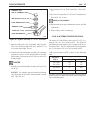
33/34 SI ALTERNATOR SPECIFICATION
The typical 33/34 SI field coil specs for 12V is 5.5 - 9.0
amps at 12V or 1.4-2.1 ohms at 80 oF. The field coil
specification for 24V models is 2.9-3.6 amps at 24V or 6.98.1 ohms at 80oF. The 32V model field coil specifications
are 1.4-1.9 amps at 32V or 17.0-21.4 ohms at 80oF.
Cold Current output at 80oF is shown in the following
table.
Alternator
Model
Amperes @ 80o F
1800 rpm
5000 rpm
12V/110A
12V/135A
60
52
110
135
24V/100A
0
100
32V/60A
8
60
For further information on rotations and exact specification
number on these or other Delco Remy America products:
Call 1-800-DRA-0222
PAGE
33/34 SI ALTERNATOR
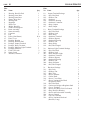
26
Illus.
No. Name
Qty.
1.
2.
3.
4.
5.
6.
7.
8.
9.
10.
11.
12.
13.
14.
15.
16.
17.
18.
19.
20.
21.
A.
B.
C.
1
1
1
1
1
1
1
1
1
1
1
1
1
N/A
1
1
1
1
1
1
1
2
3
1
Housing, Rectifier End
Bearing, Outer Race
Bearing, Inner Race
Frame, Drive End
Bearing, Ball
Regulator
Diode Trio
Bridge, Rectifier
Field Coil & Support
Rotor Assembly
Stator Assembly
Capacitor
Fan
Pulley (Not Shown)
Plate, Cover
Retainer, Bearing
Bushing, Rectifier End
Package, Output Terminal
Package, Relay Terminal
Package, Indicator Light Terminal
Package, Hardware
Field Coil Leads
Stator Leads
Insulator, Grommet
Illus.
No. Name
Qty.
18.
181.
182.
183.
184.
185.
186.
187.
Output Terminal Package
• Nut, Hex Head
• Washer, Flat
• Insulator
• Insulator, Housing
• Insulator, Connector
• Strap, Output
• Stud, Output
1
2
2
1
1
1
1
1
19.
191.
192.
193.
194.
195.
196.
197.
198.
199.
Relay Terminal Package
• Nut, Hex Head
• Washer, Lock
• Stud, Relay
• Insulator, Terminal
• Washer (Square)
• Insulator, Housing
• Washer, Flat
• Strap, Relay
• Nut, Hex Flanged
1
1
1
1
1
1
1
1
1
1
20.
201.
202.
203.
204.
205.
206.
207.
208.
209.
Indicator Light Terminal Package
• Nut, Hex Head
• Washer, Lock
• Stud, Indicator Light
• Insulator, Terminal
• Washer (Square)
• Insulator, Housing
• Washer, Flat
• Strap, Indicator
• Nut, Hex Flanged
1
1
1
1
1
1
1
1
1
1
21.
211.
212.
213.
214.
215.
216.
217.
Hardware Package
• Nut, Lock
• Washer, Flat
• Bolt, Thru
• Screw, Retainer
• Collar, Shaft
• Screw, Cover Plate
• Screw, Insulated Hex Head
(Regulator, Short)
• Nut, Hex Head
• Connector, Bridge to Regulator Stud
• Cover, Terminal
• Screw, Hex Head, Field Coil Attch.
• Plug, Rectifier Housing
• Screw and Lockwasher Assembly
• Screw, Ground
• Cap, Pin Terminal
• Screw, Insulated Hex head
(Rectifier, Long)
1
1
1
4
4
1
4
218.
219.
220.
221.
222.
223.
224.
225
226.
2
4
1
1
4
1
1
3
1
2
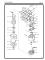
33/34 SI ALTERNATOR
PAGE
27
216
20
201
A
191
192
9
202
193
194
19
15
203
204
205
206
207 209
208
218
195
196
197
181
198
199
226
182
183
184
185
18
186
187
10
217
226
219
224
218
12
7
220
6
16
8
215
222
5
221
223A
223
4
1
214
17
213
2
3
13
212
B
211
C
11
33-6256
33/34 SI ALTERNATOR
PAGE
Delco Remy International, Inc.
2902 Enterprise Drive
Anderson, IN 46013
For further information and specifications on these and other
Delco Remy Products call: 1-800-DRA-0222
© Copyright DRI, 1G-500 10/97
Delco Remy is a registered trademark licensed by General Motors Corporation.