1
26-SI ALTERNATOR
1G/287
4/96
PAGE
1G-287
PRODUCT INFORMATION
1/98
26 SI
HEAVY DUTY
BRUSHLESS ALTERNATOR
SERVICE MANUAL
©1998 Delco Remy International Inc. All Rights Reserved.
PAGE
1G-287
4/96
26-SI ALTERNATOR
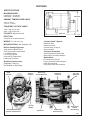
FEATURES
SPECIFICATIONS:
MAXIMUM SPEED:
Continuous: 10,000 rpm
Intermittent: 12,000 rpm
198.0 mm
AMBIENT TEMPERATURE LIMITS:
-40°C to +85°C
(-40°F to + 185°F)
TRANSIENT VOLTAGE LIMITS:
100V - 300 ms (12-volt)
250V - 300 ms (24-volt)
POLARITY: Negative Ground
302.5 mm
26-5010
ROTATION:
Clockwise or Counterclockwise
WEIGHT: 27.6 lbs (12.5 kg)
“Inside-Cooled”
MOUNTING SPAN: SAE Standard J180
Built-In Voltage Regulator
Solid-State Integrated Circuit
Flat Temperature-Compensated
Low Parasitic Draw
Low Turn-On Speed
Improved RFI Suppression
Load Dump Protection
Corrosion Protection
Sealed Rectifier-End Assembly
Brass Output Terminal Hardware
Applications
Line-Haul Diesel Trucks
Large Commercial Diesel Engines
Harsh Environments
Heavy Belt Loads and Vibrations
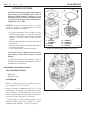
Brushless Construction
Stationary Field Coil
No Brushes or Slip Rings
Relay
Terminal
System
Baffled Air Inlet
Sealed Live Parts
Prevents entry of large or
foreign material
Output
Terminal
Extra-Large
Grease Reservoir
Stationary
Field Coil
Air Inlet
Baffles
Sealed Regulator and
Rectifier Compartment
Rectifiers
Heavy-Duty
Roller Bearing
Die Cast
Aluminum
Fan
Heavy-Duty
Sealed
Ball Bearing
26-5006
26-SI ALTERNATOR
1G/287
PAGE
4/96
1
PRODUCT INFORMATION AND SERVICE MANUAL
26-SI HEAVY DUTY BRUSHLESS ALTERNATOR
CONTENTS
Introduction ............................................................... 1
Features ..................................................................... 2
Operating Principles .................................................. 3
Troubleshooting ........................................................ 3
A. All Charging Systems .................................... 4
B. Systems with Indicator Light ......................... 4
C. Systems without Indicator Light .................... 5
D. R Terminal Accessory Problems ................... 5
E. No Output ....................................................... 5
F. Rated Output Check ....................................... 6
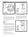
Alternator Unit Repair ............................................... 7
Disassembly and Bench Checks ......................... 7
Final Disassembly ............................................... 11
Alternator Assembly ................................................. 12
DE Frame and Rotor ........................................... 13
Rectifier End Housing and Components ............ 13
Final Alternator Assembly ................................. 16
Alternator Bench Test ......................................... 19
Alternator Mounting.................................................. 21
Service Parts .............................................................. 25
Alternator Specifications ........................................... 26
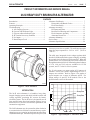
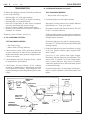
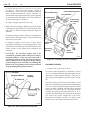
alternator rpm are also acceptable. The ambient temperature
range for proper operation is -34°C to +85°C (-30°F to
+185°F).
The solid state, integrated circuit voltage regulator built
into the 26-SI alternator limits system voltage by switching
the ground circuit for the rotor field on and off. When the
ground circuit is on, field current passes from a diode trio
through the stationary field coil. Nominal regulated voltages
of 13.8, 14.0, and 14.2 volts are available for 12 volt
systems, and 27.5 volts for 24-volt systems.
For 12-volt systems, an output rating of 85 amperes is
standard. For 24-volt systems, output ratings of 50 or 75
amperes are available. Refer to Figure 2 for graphs of
typical outputs over a range of alternator speeds. For
output ratings of specific 26-SI models refer to the
Specifications section of this manual.
26-5008
140
Figure 1. 26-SI Alternator
120
INTRODUCTION
The 26-SI series alternator is a brushless, heavy-duty
integral charging system with built-in diode rectifier and
voltage regulator, producing DC current for battery
electrical systems. The 26-SI series is designed for use on
large and mid-range diesel and gasoline engines in over
the-road service, as well as for off-road, agricultural, and
construction equipment.
The 26-SI alternator may be operated in either clockwise
or counterclockwise directions (external fan may require
changing to reverse rotation) at continuous speeds of up to
10,000 alternator rpm. Intermittent speeds of up to 12,000
A 100
M
P 80
E
R 60
E
S 40
85 amp 12V
75 amp 24V
50 amp 24V
20
1
2
3
4
5
RPM x 1000
6
7
8
26-5009
Figure 2. Typical Output vs. Alternator RPM
PAGE
2
1G-287
26-SI ALTERNATOR
4/96
FEATURES
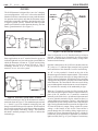
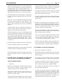
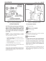
GROUND
The 26-SI alternator is designed for a “one-wire” charging
system configuration. “One-wire” refers to the minimum
number of lead wire connections necessary at the alternator
for operation and requires only that the alternator output
terminal be connected to the battery insulated (positive for
a negative-ground system) terminal and that a ground
path be provided between the alternator housing and the
battery ground terminal. (See Figure 3)
OUTPUT
TERMINAL
(B+)
"R" or "I"
TERMINAL
A
V
GENERATOR
BATTERY
26-5013
Figure 5. 26-SI Electrical Terminals
26-5011
Figure 3. Basic One-Wire System
Some applications use an “I” terminal circuit to power an
indicator light and/or to lower the engine speed (RPM) at
which the alternator will turn on. Typical system wiring
using this type of circuit is shown in Figure 4. This is
commonly referred to as a “one-wire system with I
terminal” or as a “two-wire system.”
Some 26-SI models use a 1/4" threaded stud type of output
terminal. With this type of terminal, the exposed metal
parts are not insulated and will have battery voltage when
connected to the battery.
Optional connections to the 26-SI series include either an
“R” (relay) or “I” (indicator light) terminal, and a ground
lead connection to the alternator’s rectifier end housing.
An “R” or relay terminal is located on the side of the
alternator opposite from the output terminal. This terminal
may be used to operate some types of charge indicators, an
ADLO system, a tachometer, or similar device by providing
voltage pulses at a frequency of 8 pulses for each revolution
of the alternator. The current draw of the accessories being
powered through this terminal must not exceed 4 amperes.
“R” terminals are normally of the unthreaded pin type.
GENERATOR
BATTERY
26-5012
Figure 4. One-Wire System with I Terminal
External connections to the 26-SI alternator are made to
terminals shown in Figure 5. The standard output terminal
is a “female” type with insulated connecting bolt and
charge lead cable with a special connector. When installed,
the electrical connection is sealed from moisture and there
are no exposed parts with battery voltage. The connector
bolt head is normally stamped “No Volts” to indicate the
insulated type.
When an “I” terminal is present it will be located on the
side of the alternator opposite from the output terminal, in
place of the “R” terminal. An “I” terminal is connected
internally to the field circuit. An indicator light connected
in series with this terminal will glow whenever there is a
voltage difference between the “positive” side of the field
circuit and the system voltage at other side of the indicator
light. During normal alternator operation, the light will be
off since the diode trio output voltage equals the system
voltage. A side benefit of this circuit is that current is
passed through the field winding during engine start-up,
resulting in a lower alternator turn-on speed. A diode or
resistor may be used instead of a light bulb if no indicator
light is needed. (See Fig. 4) Up to 1 ampere of current may
26-SI ALTERNATOR
1G/287
4/96
PAGE
3
be passed through this circuit to aid in alternator turn-on.
An “I” terminal is normally a threaded stud type with a 1024 thread.
induce voltages in the stator windings. The faster the rotor
turns, the higher the induced voltage will be.
A threaded 1/4" hole (with screw and lockwasher) in the
rectifier end housing between the output and “R” or “I”
terminal is provided to connect a ground lead if used;
otherwise, the ground path is through the mounting
hardware and brackets to the engine. On replacement
units, a paper tag is present identifying the “ground
screw”; remove and discard the tag. The screw and
lockwasher should be installed in the housing regardless
of whether a ground lead is connected, to prevent entry of
dirt and water.
The initial voltages at start-up are generated by residual
magnetism in the rotor. On applications with an “I”
terminal in use, this magnetism will be boosted by a small
amount of current flowing through the field from the
indicator light circuit. As speed and output increase,
voltage available at the diode trio becomes sufficient to
supply field current for normal operation. When the
output voltage exceeds the battery voltage, the alternator
begins to drive the system voltage. If the wiring system
includes an indicator light, the presence of system voltage
at the diode trio equalizes the voltage on both sides of the
indicator light and the light goes out.
All electronic parts of the alternator are sealed in a
compartment to keep out moisture and dirt, and the
alternator is “inside cooled” by air drawn through a
baffled inlet in the rectifier end cover and exiting from the
drive end frame behind the fan.
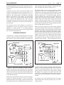
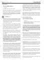
OPERATING PRINCIPLES
An alternator is a voltage-creating machine. The voltage
regulator limits the maximum voltage that the alternator
will produce at the output terminal by controlling the
While the system voltage is below the voltage regulator
setting, the regulator turns on the field current and allows
the alternator to produce as much output as possible for the
alternator speed (rpm), temperature and system voltage.
When the voltage setting is reached, the regulator turns the
field current off. When the field current is turned off, the
magnetic field in the rotor collapses and the alternator
output voltage begins to fall. The falling voltage causes
the regulator to turn the field current back on and the
magnetic field to rebuild. This switching action of the
REGULATOR
REGULATOR
CAPACITOR
DIODE TRIO
CAPACITOR
I
B+
DIODE TRIO
R
B+
ROTOR
STATOR
ROTOR
STATOR
B-
RECTIFIER BRIDGE
RECTIFIER BRIDGE
B26-5014
Figure 6. Alternator Schematic with R Terminal
magnetic field present in the stationary field. The output
voltage, induced in the stator and rectified by the diodes,
allows current to flow to satisfy the electrical loads placed
on the system, up to a maximum current that is characteristic
of the alternator design.
Schematics of the alternator circuitry are shown in Figure
6 (with “R” terminal) and Figure 7 (with “I” terminal).
With the alternator rotor turning, a magnetic field around
the stationary field coil is conducted by the rotor poles to
GROUND
26-5015
Figure 7. Alternator Schematic with I Terminal
regulator continues rapidly, keeping the output and system
voltage very close to the voltage setting. This will continue
unless the electrical demands of the system cause the
system voltage to fall below the voltage setting. Should
this happen, the regulator will again allow full field
current to flow so that the maximum output of the alternator
at the given speed, temperature and system voltage is
realized.
An internal sense lead installed between the output
terminal/diode heat sink and regulator stud, is used for
voltage control.
PAGE
4
1G-287
26-SI ALTERNATOR
4/96
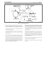
TROUBLESHOOTING
B. SYSTEMS WITH INDICATOR LIGHT TEST EQUIPMENT NEEDED:
Trouble in the charging system will normally be indicated
by one of the following:
• Jumper Lead with 5-Amp Fuse
•
•
•
•
Indicator light “on” with engine running.
Indicator light “off” with key on, engine not running.
Undercharged or overcharged battery.
Short life of light bulbs or other electric equipment
caused by abnormally high system voltage.
• System voltmeter readings outside normal range.
• Incorrect or no operation of accessories connected to
alternator “R” terminal.
1. If indicator light is on with engine running:
Stop engine. Turn key switch to “run” position. Indicator
light should be on. If not, go to Step 3.
Disconnect indicator light lead at alternator. This will
be the “I” terminal connector.
If indicator light remains on, locate and correct shorted
or grounded condition in indicator light circuit between
the light and the alternator.
Diagnose system as follows: (See Fig. 8)
A. ALL CHARGING SYSTEMS -
If indicator light goes out, light is working properly.
Proceed to “C.” for check of system with indicator light
working properly.
TEST EQUIPMENT NEEDED:
• Belt Tension Gage
• Battery State-of-Charge Indicator
2. If indicator light does not come on with the key switch
in the “run” position with the engine stopped (“bulb
check” mode):
1. Check electrical system wiring and battery terminals
for poor connections or other obvious conditions that
might result in shorts, opens, grounds, or high resistance.
Correct as necessary.
Leave key in “run” position with engine stopped.
Disconnect indicator light lead from alternator. This
will be at the “I” terminal. Use fused (5-amp) jumper
lead to ground indicator lamp circuit in harness
connector to ground screw or other clean metal ground
on alternator housing.
2. Check alternator drive belt for proper tension. Adjust
to manufacturer's specifications.
3. Check battery for state-of-charge. If low, recharge
according to manufacturer’s specifications and load
test to establish serviceability. Further diagnostic tests
require a known good, fully-charged battery for accurate
results.
- If indicator light comes on with jumper lead in place,
repair or replace alternator as described under Unit
Repair.
INDICATOR
LIGHT
KEY
SWITCH
FUSE
BLOCK
VOLTMETER
INDICATOR
LIGHT
CIRCUIT
D3,E2
D2
INDICATOR
LIGHT ("I")
CONNECTOR
"R" or "I"
TERMINAL
GENERATOR
E1
TERMINAL
CONNECTOR
(DISCONNECTED)
FUSE
OUTPUT
TERMINAL
BATTERY
B2, B3
26-5016
Figure 8. Troubleshooting a 26-SI System
26-SI ALTERNATOR
- If indicator light does not come on with jumper lead in
place, verify that alternator is properly grounded by
touching jumper lead to another ground source. If
lamp still does not light, locate and correct open circuit
in indicator light circuit. Circuit fuse may be open or
light bulb may be burned out. Correct as necessary.
3. If indicator light comes on while engine is running, but
is not on with engine stopped and key switch in “run”
position:
Leave key in “run” position with engine stopped.
Disconnect indicator light lead from alternator. This
will be at the “I” terminal. Use fused (5-amp) jumper
lead to ground indicator lamp circuit to alternator
housing.
- If indicator light comes on with jumper lead in place,
replace internal indicator light lead assembly or
regulator as described under Unit Repair.
- If indicator light does not come on with jumper lead in
place, locate and correct open circuit in indicator light
circuit between battery and light. Circuit fuse may be
open. (With engine running, light is being powered by
alternator and grounded through other circuits
connected in parallel to indicator light circuit.) Correct
as necessary.
4. If indicator light is on with key switch in “off” position:
1G/287
4/96
PAGE
5
- If voltage reading at battery terminals is different from
reading showing at system voltmeter (if equipped),
locate and correct cause of incorrect reading.
- If voltage is lower than reading previously recorded
with engine stopped, there is no alternator output.
Proceed to section on No Output.
- If voltage is higher than previous reading with engine
stopped, alternator output is present. Proceed to Rated
Output Check.
2. If battery is overcharged (as evidenced by excessive
water use or electrolyte spewing from battery vents), or
light bulbs or other electrical equipment have shortened
life due to suspected high system voltage, or system
voltmeter reads above normal range:
With fully charged battery, engine running at moderate
speed and all electrical loads off, use voltmeter to
check voltage at battery terminals.
For a 12-volt system, readings should be stable, around
13.5 - 14.5 volts and in no case go above 15 volts. For
a 24-volt system, readings should be stable, around 27
- 28 volts and in no case go above 31 volts.
- One-wire system: If voltage is erratic or goes above 15
volts (31 volts on 24-volt system), check internal sense
circuit and regulator as described under Unit Repair.
Disconnect indicator light circuit at alternator.
- If indicator light remains on, locate and correct shorted
condition between the light and alternator.
D. R TERMINAL ACCESSORY PROBLEMS
1. Disconnect lead from “R” terminal.
- If indicator light goes out, diode is shorted in rectifier.
Locate and replace diode as described under Unit
Repair.
2. Start engine and run at moderate speed. Check system
voltage across battery terminals with engine running.
Record voltage.
C. SYSTEMS WITH VOLTMETER, NO INDICATOR
LIGHT, OR WITH LIGHT WORKING PROPERLY -
3. Use voltmeter to check voltage between “R” terminal
and alternator ground screw or other clean metal ground.
TEST EQUIPMENT NEEDED:
• Voltmeter
1. If battery is undercharged, indicator light remains on
while vehicle is running, or system voltmeter shows
operating voltage is below acceptable range:
With engine stopped and all electrical loads off, use
voltmeter to check system voltage across battery
terminals. Record voltage.
Start engine and run at moderate speed. Check system
voltage across battery terminals with engine running.
- If voltage is near half of system voltage, “R” terminal
output is O.K. Note that this is a pulsating signal, so
some voltmeters may give an unsteady reading.
- If no voltage is present, replace diode trio assembly as
described under Unit Repair.
- If voltage is nearly the same as the alternator output
voltage, disassemble alternator as described under
Unit Repair and check to see if terminal is connected to
diode trio lead. If so, replace diode trio assembly. If
terminal is connected to regulator, it is wired as an “I"
terminal and can’t be used as an “R” terminal.
PAGE
6
1G-287
26-SI ALTERNATOR
4/96
E. NO OUTPUT
TEST EQUIPMENT NEEDED:
• Voltmeter
• Jumper Lead (18 ga. min; no fuse)
Note that 26-SI alternators must be connected to a
battery for the voltage sensing circuit to allow initial
turn on (refer to section on Features). When properly
connected and system checks indicate a “no output”
condition, use the following steps to determine if the
alternator requires repair:
! IMPORTANT
On alternators with insulated output terminal, voltage
in battery cable at output terminal cannot be checked
by touching voltmeter to connecting bolt. Disconnect
output terminal and check voltage at inner ring in
terminal connector of cable.
1. For alternators without an “I” terminal in use, battery
positive voltage at the output terminal and residual
magnetism in rotor are necessary for alternator to turn
on. With engine stopped, use voltmeter to verify that
battery voltage is present in cable at output terminal. If
not, locate and correct cause of voltage loss.
Residual magnetism in the rotor is sometimes lost
during servicing of the alternator. The rotor can normally
be remagnetized without removing alternator from
application.
CAUTION: Do not allow jumper lead to be
accidentally grounded while connected to battery
insulated terminal. If the free end of this lead is
accidentally touched to the alternator housing or
other grounded areas, the jumper lead may quickly
get hot enough to cause a skin burn or to damage the
jumper lead. Keep jumper lead carefully insulated
from grounding during this procedure.
To remagnetize rotor, make sure the normal
connections are made to the alternator output terminal
and to the ground circuit. Disconnect the wiring harness
from the “R” terminal. Momentarily connect a jumper
lead from battery positive to the alternator “R” (or
unused “I”) terminal. (See Fig. 48) This will cause
field current to momentarily flow through the field
windings in the proper direction and restore magnetism.
Reconnect wiring harness to “R” terminal, then recheck
alternator for output.
2. For systems with an “I” terminal in use, the indicator
light current at this terminal will establish normal
magnetism at each engine start-up. Such systems may
depend on this current to help ensure a low turn-on
speed of the alternator. With engine stopped and key
switch in “run” position, use voltmeter to check for
voltage present at this terminal. With “I” terminal
connected and indicator lamp on, voltage will be less
than battery voltage. If necessary to disconnect wiring
at “I” terminal to make this check, check for battery
voltage in harness wire. If voltage is present, proceed
to Step 3. If no voltage is present, check “I” terminal
circuit for cause of voltage loss (bulb may be burned
out). Correct as necessary.
3. If no conditions have been found that might prevent the
alternator from turning on (Step 1 or 2), remove
alternator from engine in accordance with engine
manufacturer’s instructions and proceed to Unit Repair.
F. RATED OUTPUT CHECK
TEST EQUIPMENT NEEDED:
• Voltmeter
• Ammeter (current capability at least 15 amperes
higher than alternator rating)
• Variable Carbon Pile Load Test
CAUTION: Failure to disconnect grounded battery
cable at battery before removing or attaching battery
cable at alternator output terminal may result in an
injury. If a tool is shorted to the battery cable
connector at the output terminal, the tool can quickly
heat enough to cause a skin burn or the tool or cable
may be damaged.
1. Refer to Fig. 9 for test equipment hookups as described
in following steps. If inductive pickup (“clamp on”)
type ammeter is used, place current clamp on alternator
output lead and skip to Step 4. If series ammeter is used,
disconnect grounded battery cable at battery first.
2. Install ammeter in series with alternator output terminal.
3. Reconnect grounded battery cable at battery.
4. NOTICE: When a 12-volt carbon pile load test is used
to diagnose a 24-volt system attach load test only to 12volt potential in battery pack. Attaching a 12-volt load
test to a 24-volt potential will damage the load test.
With load turned off, attach carbon pile load test across
battery.
5. Attach voltmeter lead to grounded battery terminal,
observing proper polarity for system. Leave other
voltmeter lead open for checks at various points.
6. Check and record voltage at insulated battery terminal.
For multi-battery systems, check voltage of battery set
connected as if in battery charging mode.
7. With all system electrical loads off, start engine and
run at moderate speed (rpm).
26-SI ALTERNATOR
1G/287
CLAMP-ON
AMMETER
4/96
PAGE 7
CARBON
PILE
A
F9
F6,F8
BATTERY
ALTERNATOR
V
VOLTMETER
F5
26-5017
Figure 9. Rated Output Check
8. Recheck voltage at insulated battery terminal. Voltage
should be higher than previous reading, but below 15
volts on 12-volt system (31 volts on 24 volt system).
- If reading is lower than previous reading (Step 6), refer
to section on No Output.
- If reading is higher than 15 volts on 12-volt system (31
volts on 24-volt system), refer to section on High
Voltage Output.
9. Turn carbon pile load on and adjust to obtain maximum
alternator output on ammeter. Record maximum output.
With alternator still running at maximum output, check
and record voltage drop in ground circuit between
alternator housing and grounded battery terminal. Then
check voltage drop from output terminal to battery
positive. Turn carbon pile load off.
Maximum ampere output should be within 15 amps of
output rating stamped on alternator identification plate,
or as listed in Specifications section of this manual.
Voltage drop should be 0.25 volts or less for each
voltage drop test on 12-volt system (0.5 volts or less on
24-volt system).
- If ground circuit voltage drop is over 0.25 volts on 12
volt system (0.5 volts on 24-volt system), clean and
tighten all ground circuit connections. If this does not
correct excessive voltage drop, check ground circuit
cables for improper sizing or high resistance conditions.
Correct as necessary.
- If within 15 amps of rating, alternator is good. Look
elsewhere for cause of problem.
- If more than 15 amps below rating, repair or replace
alternator.
PAGE
8
1G-287
26-SI ALTERNATOR
4/96
ALTERNATOR UNIT REPAIR
20
CAUTION: Disconnect grounded cable at battery
before removing or attaching battery cable at
alternator output terminal. Otherwise, a tool
shorted to the battery cable at the output terminal
can quickly heat enough to cause a skin burn or
damage the tool or cable.
47
33
1
32
NOTICE: Always reinstall fasteners at original
location. If necessary to replace fasteners, use only
correct part number or equivalent.
• If correct part number is not available, use only
equal size and strength. For alternator internal
fasteners, refer to Delco Remy America Standard
Hardware Fasteners section in Service Parts
Catalog.
• Fasteners that are NOT to be reused will be noted
in procedure.
• Fasteners requiring thread locking compound will
be noted in procedure.
• Use specified torque values when shown.
34
19
1. HOUSING
ASSEMBLY
19. COVER
20. PLATE
32.
33.
34.
47.
SCREW (3)
SCREW (4)
SCREW (4)
GASKET
26-5018
Figure 10. Removing End Plate and Cover
CAUTION: Using or replacing fasteners in any
other manner could result in part or system
damage.
If diagnosis determines that alternator repair is
needed, remove alternator from engine according to
manufacturer’s instructions.
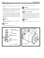
DISASSEMBLY AND BENCH CHECKS
TEST EQUIPMENT NEEDED:
• Multimeter
• Regulator Tester
ALTERNATOR
1. Remove rectifier end plate (20), rectifier end cover
(19), and gasket (47). (See Fig. 10)
2. Inspect electronics compartment (See Fig. 11) for
contamination, for shorted or grounded wires, and for
loose connections. If contamination is present, clean
and dry compartment before proceeding. Check gasket
for source of entry and replace as necessary.
If indicator light was not operating properly, check
internal indicator light lead assembly for correct
installation and continuity. Correct as necessary.
26-5019
Figure 11. Electronics Compartment
26-SI ALTERNATOR
OHMMETER
1G/287
9
26
35
35
PAGE
4/96
36
9
53
36
37
9
41
54
1
1. HOUSING
ASSEMBLY
9. REGULATOR
26. NUT
36. SCREW (2)
37. SCREW
41. WASHER
52. LEAD
53. LEAD
54. PLATE
9. REGULATOR
35. SCREW (GROUND)
36. SCREW (INSUL.)
26-5021
26-5020
Figure 12. Checking Field Coil Resistance
FIELD COIL
3. Disconnect 2 field leads from regulator (9) by removing
2 insulated regulator attachment screws (36). (See Fig.
12) Use ohmmeter to check resistance of field coil.
Compare to Field Check ohms in Specifications at the
end of this manual or from Service Specification
Bulletin. If outside specifications, replace field coil as
described later in this section.
REGULATOR
4.
Figure 13. Removing Regulator
(25). (See Fig. 14) Disconnect diode trio assembly’s
capacitor lead from heat sink by removing screw (31)
and insulator (51). If necessary to remove from
alternator completely, disconnect diode trio assembly’s
“R” terminal lead (if used) from inside of “R” terminal
by removing nut (25), then remove attaching screw
(38) from grounding tab.
38
31
40
49
IMPORTANT
Back (metal side) of regulator and both sides of regulator
mounting plate are coated with silicone heat transfer
grease. If this grease is removed during testing, recoat
as described under regulator installation in this section.
To remove regulator (9) for testing, remove sense lead
nut (26) and grounded mounting screw (37). (See Fig.
13) It is not necessary to remove the regulator mounting
plate (54), but it may come off with the regulator (if it
does, pull the plate from the regulator and place it back
in the alternator to keep from contaminating the grease).
Check regulator on approved tester for SI type
regulators. If regulator tests “good”, return it to service.
If it tests “bad”, replace it. Install regulator as described
later in this section.
DIODE TRIO/CAPACITOR ASSEMBLY
5. Disconnect diode trio assembly’s (15) 3 phase leads
from the diode junction studs by removing the nuts
25
51
15
1
1. HOUSING
ASEMBLY
15. DIODE TRIO
25. NUT
31. SCREW (2)
37. SCREW
38. SCREW
40. WASHER
49. GROMMET
54. INSULATOR
26-5022
Figure 14. Disconnecting Diode Trio Assembly
PAGE
10
1G-287
26-SI ALTERNATOR
4/96
A
25. NUT (3)
E
OHMMETER
G
15
OHMMETER
D
C
25
F
B
13. DIODE STUD PACKAGE
15. DIODE TRIO ASSEMBLY
13
STATOR PHASE
LEAD CONNECTION
26-5023
26-5024
Figure 15. Electrical Check of Diode Trio Assembly
6. Use ohmmeter or diode check function on multimeter
to check diode trio (15). (See Fig. 15) Place negative
ohmmeter lead on regulator lead (A) and use positive
ohmmeter lead to check for continuity to each of the
three phase leads (B, C, D). All three readings should
indicate continuity. Reverse the ohmmeter leads and
perform checks again. Readings should all indicate
open circuits.
Using continuity check mode (diode check mode on
digital meter), check for a shorted capacitor by touching
ohmmeter leads to capacitor lead (F) and grounding tab
(G). This check should show an open circuit.
Figure 16. Checking Stator Windings
To check for grounds, again touch one meter lead to
one of the stator phase leads, and touch the other meter
lead to clean metal ground on the alternator housing.
There should not be continuity. If there is continuity,
the stator is grounded and should be replaced as
described later in this section.
It is not possible to detect shorted stator windings with
ordinary shop equipment. However, if all other electrical
checks are normal and the alternator has exhibited low
output, shorted stator windings may be the cause. In
such cases, replace the stator as described later in this
section.
OHMMETER
If the alternator has an “R” terminal, check the “R”
terminal circuit by checking for continuity between the
“R” terminal lead (E) and each of the phase leads (B, C,
and D). There should be continuity to one (and only
one) of these leads.
If any of these checks are not as indicated above,
replace the diode trio assembly (15). Install assembly
as described later in this section.
RECTIFIER
DIODE LEADS
STATOR
10
10
7. Disconnect the 3 stator phase leads from the diode
junction studs by removing nuts (25). Use continuity
check function of ohmmeter to check stator windings.
(See Fig.16) Place one meter lead on one of the stator
phase lead connectors and check for continuity to each
of the other two stator leads. There should be continuity
to both. If not, one or more of the stator coils is open;
replace the stator as described later in this section.
11
14
10. IN FRAME DIODE
11. HEAT SINK DIODE
14. HEAT SINK ASSEMBLY
OHMMETER
26-5025
Figure 17. Checking Rectifier Diodes
26-SI ALTERNATOR
1G/287
4/96
PAGE
11
RECTIFIER DIODES
31
39
8. Disconnect the 6 diode leads from the 3 diode junction
studs by removing nuts. (See Fig. 17) Find the three
output side diodes (11), which are installed in the heat
sink (12). These diodes will be identical in polarity and
will commonly have the same color of insulation on the
diode lead wire.
Use the ohmmeter or (for digital meters) the diode
check function of the multimeter to check the diodes.
Place one of the meter leads on a clean metal section of
the heat sink and connect the other lead to each of the
3 diode lead connectors, without allowing the connectors
to touch any other metal part. All 3 of these diodes
should read nearly the same, either all “open” or all low
resistance.
Reverse the leads and repeat these checks. All 3 diodes
should again read nearly the same, but should be
opposite from the first reading. If a diode reads the
same (either “open” or low resistance) in both checks,
replace it as described later in this section. If one diode
seems to have polarity opposite from the other two, or
if there is a question about whether the diodes are
installed properly for the polarity of the alternator,
refer to Fig. 18 for proper configuration.
ALTERNATOR
GROUND
NEGATIVE
POSITIVE
OUTPUT
DIODES
GROUND
DIODES
CURRENT
FLOW FROM
CURRENT
FLOW FROM
LEAD TO
HEAT SINK
RED WIRES
HOUSING TO
LEAD
BLACK WIRE
HEAT SINK
IS LEAD
BLACK WIRE
14
51
50
16
1.
14.
13.
16.
17.
31.
39.
50.
51.
HOUSING
HEAT SINK
ASSEMBLY
STUD PACKAGE
TERMINAL
TERMINAL
SCREW
WASHER
INSULATION
INSULATOR
17
1
26-5027
Figure 19. Removing Heat Sink from Housing
9. Find the three ground side diodes (10) mounted in the
rectifier end housing (1). (See Fig. 17) These diodes
will be identical in polarity and will commonly have
the same color of insulation on the diode lead wire.
Repeat the diode check described above (Step 8),
except use clean metal ground on the rectifier housing
instead of the heat sink. Refer to Fig. 18 to determine
proper polarity.
10. To replace one or more of the rectifier diodes,
disconnect all diode leads from the diode junction
studs (13). Remove three heat sink attachment screws
(31) and insulators (51), then remove the alternator
output terminal (16) by removing the inside nut,
washer, and insulator (17). (See Fig 19)
!
IMPORTANT
Back of heat sink and both sides of heat sink
insulator are coated with silicone heat transfer grease.
If this grease is removed during testing, recoat as
described under regulator installation in this section.
LEAD TO
HOUSING
RED WIRE
26-5026
Figure 18. Diode Polarity
13
Remove the heat sink and diode assembly (14) from
the rectifier end housing (1). (See Fig. 19) The
insulator (50) between the heat sink and housing may
come out with the heat sink. If it does, carefully peel
it from the heat sink. Check insulator for damage that
might result in a grounded condition and replace if
necessary. If insulator is to be reused, place it back
in the housing to prevent contamination of the grease.
PAGE
12
1G-287
26-SI ALTERNATOR
4/96
31
39
25
1. HOUSING ASSEMBLY
10. IN FRAME DIODE (3)
11
10
12
51
1
13
10. HEAT SINK
DIODE (3)
11. HEAT SINK
DIODE (3)
12. HEAT SINK
13. STUD
PACKAGE (3)
25. NUT (3)
31. SCREW (4)
39. WASHER (4)
50. INSULATION
51. INSULATOR (4)
10
49
26-5029
26-5028
Figure 20. Removing Heat Sink Diodes
11. NOTICE: Do not hit diodes or diode mountings with
a hammer or other tool. The shock of such an impact
can damage the diode or other diodes in the same
mounting. Use proper tools to press or pull diodes
from their mountings.
Replacing one or more diodes requires the use of an
arbor press or vise, and special diode removal and
installation tools. Such tools are available from
various automotive tool suppliers. When removing a
diode (11) from the heat sink (12), (See Fig. 20) press
diode from heat sink using an arbor press or vise.
When removing a diode (10) from the rectifier end
housing (1), (See Fig. 21) use a diode puller. As much
as 890 N (200 lbs.) of force may be needed to remove
a diode.
FINAL DISASSEMBLY
NOTICE: Do not damage exposed stator or field
windings.Bumping or scraping these windings may
break the insulation and leave a place for a short circuit
or ground to develop later, causing the alternator to fail.
Protect the windings from damage by careful handling.
12. To replace the field coil, stator assembly, rotor
assembly, or drive end or rectifier end bearings, the
drive end frame assembly must be separated from the
rectifier end housing. (Fig. 22) Use 5/16" hex wrench
or 5/16" hex drive, in the end of the shaft, to hold while
removing shaft nut (27). Remove washer (42), pulley,
and fan (23) from shaft, along with baffle and slinger
Figure 21. Removing Diodes from Housing
if used. Remove the 4 thru bolts (43). Carefully
separate the drive end housing from the stator and
rectifier end housing, taking care not to damage stator
windings. (See Fig. 23)
13. To remove stator from rectifier end housing, be sure
all 3 stator leads are disconnected from diode junction
studs in electronics compartment. Pry stator (5) and
1
23
PULLEY
WRENCH
27
42
TORQUE
WRENCH
1. ALTERNATOR
ASSEMBLY
23. FAN
27. NUT
42. WASHER
26-5030
Figure 22. Alternator Disassembly
26-SI ALTERNATOR
1G/287
4/96
PAGE
13
29
1.
8.
29.
49.
1
HOUSING ASSEMBLY
FIELD COIL ASSEMBLY
SCREW (3)
GROMMET
1
5
6
1. HOUSING
ASSEMBLY
5. STATOR
6. DRIVE FRAME
ASSEMBLY
43. THRU-BOLTS (4)
8
49
43
26-5031
26-5033
Figure 23. Separating Housings
Figure 25. Removing Field Coil
housing (1) apart carefully. Guide stator leads and
grommet (48) through hole as stator is pulled from
housing. It may be necessary to push on grommet
with a blunt instrument to unseat it from the housing.
(See Fig. 24)
14. To remove field coil and support from rectifier end
housing, (See Fig. 25) remove 3 field coil and support
attaching screws (29). Lift coil and support from
housing, while guiding field leads and grommet
through hole.
NOTICE: Do not drive bearing out with hammer or
other tool. Shocks from striking the rectifier end housing
can damage diodes mounted inside. Use arbor press to
push bearing from housing.
Wipe excess grease from bearing well, then press
bearing through to inside of housing.
16. If bearing inner race (3) appears to be worn or rough,
remove from rotor shaft (See Fig. 26) with a suitable
puller.
15. To remove rectifier end bearing outer race (2) from
housing, (See Fig. 26) use small screwdriver at slot to
pry cap from housing.
3
4
5
48
52
2
55
46
1. HOUSING
ASSEMBLY
5. STATOR
46. CLIPS (3)
48. GROMMET
52. INSULATION
1
1
26-5032
Figure 24. Removing Stator
1.
2.
3.
4.
55.
HOUSING ASSEMBLY
OUTER RACE BEARING
INNER RACE BEARING
ROTOR ASSEMBLY
CAP
26-5034
Figure 26. Removing Rectifier End Bearing
PAGE
14
1G-287
26-SI ALTERNATOR
4/96
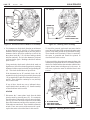
17. To replace rotor (4) or drive end bearing (7), (See Fig.
27) remove 4 bearing retainer attachment screws (28)
from outside of housing (1). Lift rotor with bearing
from housing, then pull bearing off of rotor shaft. If
inside collar (22) appears rough or damaged, pull
collar from shaft.
4.
6.
7.
21.
22.
28.
ROTOR ASSEMBLY
DRIVER FRAME
BEARING
RETAINER
COLLAR
SCREWS (4)
18. NOTICE: Do not drive mounting hinge bushing
from lug on rectifier end housing with a hammer or
other tool. Impact shocks from striking the rectifier
end housing can damage diodes mounted inside. Use
arbor press or vise to remove bushing.
To remove mounting hinge bushing (44) from lug on
rectifier end housing (1), (See Fig. 28) press bushing
from housing.
4
21
22
7
1
6
44
INSTALL FLUSH
WITH INSIDE
OF LUG
28
1.
44.
HOUSING ASSEMBLY
BUSHING
26-5035
Figure 27. Disassembly of Drive End Components
26-5036
Figure 28. Removing Slip Bushing
26-SI ALTERNATOR
1G/287
4/96
PAGE
15
ALTERNATOR ASSEMBLY
7
21
ASSEMBLY OF DE FRAME AND ROTOR
22
4
INSTALL OR CONNECT
1. Press inner race for rectifier end bearing (3) onto short
end of rotor shaft. Stop when race is 3.7 mm (.15 in.)
above end of shaft. (See Fig. 29)
2. Press inside collar (22) onto rotor shaft until collar is
against shoulder on rotor (4). (See Fig. 29) Place
retainer plate (21) onto collar (flanged side of retainer
will face away from rotor, toward bearing). Using open
tube that bears only on inner race of bearing, press new
DE bearing onto rotor shaft until bearing is against
collar.
3.7MM
3
3.
4.
7.
21.
22.
RECTIFIER
END
BEARING
ROTOR
ASSEMBLY
BEARING
RETAINER
COLLAR
26-5037
Figure 29. Rotor Assembly
4.
6.
7.
21.
22.
28.
ROTOR ASSEMBLY
DRIVER FRAME
BEARING
RETAINER
COLLAR
SCREWS (4)
3. Insert DE bearing (7) (on rotor shaft) into bearing well
in drive end frame (6). (See Fig. 26) Bearing (7) will
be a snug fit, but should slip in easily when properly
aligned. Lubricate outside of bearing very lightly with
ball and roller bearing lubricant (1948791) if necessary
to facilitate assembly.
4. Hold drive end assembly (6) with long end of rotor
shaft down so that bearing retainer plate (21) falls
against housing (1), then align retainer with screw
holes. (See Fig. 30) Start each of the four retainer
attaching screws (28), then tighten screws gradually in
sequence to pull retainer squarely against bearing.
4
TIGHTEN
Bearing retainer attaching screws (28) to 5 N.m (45 lb.
in.).
21
! IMPORTANT
22
To allow access for later installation of thru bolts, do
not assemble fan and pulley to drive end assembly at
this time.
7
ASSEMBLY OF RECTIFIER END HOUSING AND
COMPONENTS
6
INSTALL OR CONNECT
5. NOTICE: Do not drive hinge bushing into lug on
rectifier end housing with a hammer or other tool.
Impact shocks from striking the end housing can damage
diodes mounted inside. Use arbor press or vise to press
bushing into place.
28
26-5035
Figure 30. Installing Rotor in Drive End Frame
PAGE
16
1G-287
26-SI ALTERNATOR
4/96
1. RECTIFIER END
HOUSING
2. OUTER BEARING
RACE
3. INNER BEARING
RACE
4. ROTOR
ASSEMBLY
55. PLUG
1
1
44
2
INSTALL FLUSH
WITH INSIDE
OF LUG
1.
44.
HOUSING ASSEMBLY
BUSHING
55
26-5036
3
Figure 31. Installing Slip Bushing
2
Lightly lubricate outside surface of hinge bushing (44).
Press hinge bushing into hole in lug on rectifier end
housing (1). Install bushing flush with inside of lug to
allow maximum distance between two hinge lugs for
mounting. Final position of hinge bushing will be
adjusted during mounting. (See Fig. 31)
6. Position new rectifier end bearing (2) to rectifier housing
(1) so that seal will be toward rotor (4) as alternator is
assembled. Press against seal side of bearing to assemble
into housing until opposite end of bearing is 16.5 mm
(.65 in.) from edge of housing. (See Fig. 32) Push cap
into other end of housing until outside edges are flush
with edge of housing.
7. Add ball and roller bearing lubricant (1948791) until
cavity between plug (55) and bearing outer race (2) is
about half full, placing grease so that it touches the edge
of the outer race in several places around the outside of
the bearing.
8. NOTICE: When installing diodes, do not hit diodes or
diode mountings with a hammer or other tool. The
shock of such an impact can damage the diode or other
diodes in the same mounting. Use proper tools to press
diodes into their mountings.
4
26-5038
Figure 32. Installing Rectifier End Bearing
Use diodes only as specified in the Delco Remy America
Service Parts Catalog when replacing diodes. Heat sink
(output) diodes and in-frame (grounding) diodes will
be similar in appearance except for color of wire
insulation and color markings on the diode itself. The
two types are opposite in polarity and must not be
mixed. Also, the polarity of diodes used in negative
ground systems will be opposite of those used in positive
ground systems. Note that a new heat sink assembly
comes with new diodes already installed. A new heat
sink assembly may be installed instead of replacing
individual output diodes, if desired.
Replacing one or more diodes requires the use of an
arbor press or vise, and special diode removal and
installation tools. Such tools are available from various
automotive tool suppliers. When installing a diode,
press diode into mounting using a tool that will bear
only on the outer edge of the diode. As much as 890 N
(200 lbs.) of force may be needed to install a diode.
26-SI ALTERNATOR
1G/287
31
39
4/96
13
1
1.
14.
13.
16.
17.
31.
39.
50.
51.
17
HOUSING
HEAT SINK
ASSEMBLEY
STUD PACKAGE
TERMINAL
TERMINAL
SCREW
WASHER
INSULATION
INSULATOR
26-5029
1
26-5027
Figure 33. Installing In-Frame Diodes
Figure 35. Installing Heat Sink
• Position new in-frame diodes (10) to rectifier end
housing (1) so that leads will reach the diode junction
studs (13). (See Fig. 33) Using suitable diode
installation tools, press new diodes into housing.
• Position new heat sink diodes (11) to heat sink (12)
so that leads will reach the diode junction studs (13).
(See Fig. 34) Using suitable diode installation
tools, press diodes into heat sink.
31
11
12
51
13
11. HEAT SINK
DIODE (3)
12. HEAT SINK
13. STUD
PACKAGE (3)
25. NUT (3)
31. SCREW (4)
39. WASHER (4)
51. INSULATOR (4)
26-5039
Figure 34. Installing Heat Sink Diodes
14
50
16
39
25
17
51
10
1. HOUSING ASSEMBLY
10. IN FRAME DIODE (3)
PAGE
9. Push square plastic retainers for diode junction studs
(13) into square holes in heat sink. Insert metal studs
into holes in retainers and push in until shoulder on stud
is seated against retainer. This spreads the retainer legs
and secures the retainers in the holes. (See Fig. 34)
10.
! IMPORTANT
Avoid getting silicone dielectric grease on diode lead
clips or on electrical contact surfaces around mounting
screw holes on top of heat sink. If grease does get on
these areas, wipe away with a clean cloth slightly
dampened with a grease-dissolving solvent and allow
to dry.
Using silicone dielectric grease (1974984) for heat
transfer, coat mounting area in rectifier end housing
and both sides of insulator to be placed between diode
heat sink and rectifier housing. Place insulator flat in
rectifier end housing over mounting holes. Coat back
side of heat sink with same grease, in the area where it
will contact the housing. Position inside insulating
washer for output terminal between hole in housing
and slot in heat sink. Install heat sink assembly (14)
to rectifier end housing (1) over insulator (50), aligning
mounting holes. Install insulators (51), flat washers
(39), and 2 heat sink attaching screws (31) that will not
have electrical connections. (See Fig. 35) Insulators
must be next to the heat sink. Finger tighten screws.
Edge of insulator should be visible all around heat
sink.
PAGE
18
1G-287
26-SI ALTERNATOR
4/96
11. Place insulator (17b) on output terminal (17a) and
install through hole in housing (1). (See Fig. 36) Install
flat insulator washer (17c), aligning flat shoulders on
terminal with slot in heat sink to fully seat terminal.
Install nut/washer assembly (17d) onto threaded portion
of terminal inside housing. Tighten nut to 5 N.m (45
lb. in.).
12.
29
1
TIGHTEN
Two previously installed heat sink mounting screws
(31) to 3 N.m (26 lb. in.).
13. Lubricate grommet (49) on field coil leads lightly with
petroleum jelly. Turn grommet and leads so that leads
will be properly positioned after installation. (See Fig.
37) Place field coil and support (8) into rectifier
housing (1), guiding leads through hole into electronics
compartment and aligning mounting holes in support
with screw holes in rectifier housing. Push grommet
into hole in housing until fully seated. Install 3 field
coil and support attachment screws (29).
14. NOTICE: Handle stator with care to avoid bending
windings or breaking varnish insulation on windings.
If windings are damaged before or during installation,
they may become shorted and cause reduced alternator
output.
Straighten stator leads to ease installation. Lubricate
grommet (48) on stator leads lightly with petroleum
jelly. Welded junction connector on stator must be
OUTPUT
TERMINAL (16)
8
49
1.
8.
6.
49.
HOUSING ASSEMBLY
FIELD COIL ASSEMBLY
SCREW (3)
GROMMET
26-5033
Figure 37. Installing Field Coil
positioned straight up from windings to prevent
grounding to housing or rotor when alternator is
assembled. Straighten stator lead wires all the way to
the windings and insert through hole in housing into
electronics compartment. (See Fig. 38)
Align thru-bolt holes in stator (5) with those in housing
(1). Push stator into housing far enough to hold it in
place, being sure grommet (48) on wires is inserted
into hole in housing at the same time. Stator lead wires
should be stiff enough to push grommet into hole as
stator is installed (if not, carefully push on grommet
with a blunt instrument to seat it in the hole). It is not
necessary for the stator to be fully seated in housing at
this time.
17a
5
17b
48
52
HOUSING (1)
OPTIONAL (17)
46
17c
1. HOUSING
ASSEMBLY
5. STATOR
46. CLIPS (3)
48. GROMMET
52. INSULATION
HEAT
SINK (14)
17d
1
26-5040
Figure 36. Installing Output Terminal
26-5032
Figure 38. Installing Stator
26-SI ALTERNATOR
1G/287
FINAL ALTERNATOR ASSEMBLY
15.
CLEAN
Inner race of rectifier end bearing (on rotor shaft) to
prevent contamination of grease.
16. Align mounting lugs and assemble two halves of
alternator (See Fig. 39), inserting rectifier end bearing
inner race (on rotor shaft) into rectifier end bearing in
rectifier housing. Do not fully seat drive end housing
at this time.
17. Insert 4 thru-bolts (43) through drive end housing (6)
and stator (5) into threaded holes in rectifier housing
(1). Align housings and stator as needed to allow thrubolts to stand straight in holes and engage threads.
When all four thru-bolts are inserted, tighten them in
round-robin fashion to fully seat both housings against
shoulder on stator.
TIGHTEN
4/96
PAGE
19
18. Install diode trio assembly (15) to rectifier end housing.
(See Fig. 40) Install diode trio and capacitor attachment
screw (38). This screw provides a ground for the
capacitor in the diode trio assembly and must hold tab
securely. Tighten to 3 N.m (26 lb. in.).
NOTE: On 25-SI alternators that have been converted
to 26-SI electronics, coat the threads of the attachment
screw with high temperature adhesive/sealant (LoctiteC
272 or equivalent) prior to installation.
19. Place two diode lead clips onto each diode junction
stud (13) in the heat sink assembly (14). Next, place
one stator lead onto each of these studs, matching the
length of the leads to the appropriate studs. Finally,
place one yellow diode trio lead onto each stud, again
matching the length of the lead to the appropriate stud.
Install a diode trio to stator lead attaching nut (25) onto
each diode junction stud. Position clips under nuts so
that leads are routed without being pinched or pulled
tight against sharp surfaces. Tighten nuts to 3 N.m 26
(lb. in.).
Thru-bolts to 6.2 N.m (55 lb. in.)
40
14.
13.
15.
25.
38.
39.
40.
51.
38
1
DIODE LEAD
(6 PLACES)
MOUNTING HOLE
5
13
15
6
HEAT SINK ASSEMBLY
STUD PACKAGE
DIODE TRIO ASSEMBLY
NUT
SCREW
WASHER
WASHER
INSULATOR
1. HOUSING
ASSEMBLY
5. STATOR
6. DRIVE FRAME
ASSEMBLY
43. THRU-BOLTS (4)
43
26-5031
Figure 39. Assembly of Alternator Halves
39
31
51
25
14
26-5041
Figure 40. Installing Diode Trio Assembly
PAGE
20
1G-287
26-SI ALTERNATOR
4/96
20. Place clip of red diode trio lead over hole in heat sink,
then install insulator (51), flat washer (39), and heat
sink attachment screw (31). (See Fig. 40)
TIGHTEN
Heat sink attachment screw to 3 N.m (26 lb. in.).
21. Place “R” or “I” terminal (18) into hole in rectifier
housing (1). Place insulating washer and plain washer
onto stud inside housing. (See Fig. 41) If alternator
uses “R” terminal, place yellow “R” terminal lead
from diode trio assembly (15) onto inside terminal
stud (18). If alternator has “I” terminal, install indicator
light lead assembly onto inside terminal stud. Install
inside terminal nut. Hold external hex portion of
terminal as anti-turn.
TIGHTEN
NOTE: On 25-SI alternators that have been converted
to 26-SI electronics, a spacer is installed between the
plate and housing at hole C prior to installing the plate.
Coat both ends of spacer with silicone dielectric grease
before placing over hole C in housing.
23. Coat back (metal side) of regulator (9) with silicone
dielectric grease (1974984). Place regulator onto
mounting plate, aligning mounting holes with those in
rectifier end housing. Install regulator grounding
attachment screw/washer assembly (35) (1" long)
through regulator and mounting plate into housing
hole D. Finger tighten.
24. Place “I” terminal lead (if used), blue lead from diode
trio, and long field coil lead over hole B (See Fig. 42)
and insert insulated regulator attachment screw (35)
(1" long). Place short field coil lead over hole C and
insert insulated regulator attachment screw (36) (1"
long). Finger tighten both screws.
Inside “R” or “I” terminal nut to 2.3 N.m (20 lb. in.).
22. Coat regulator mounting area in rectifier end housing
(1) and both sides of regulator mounting plate (54)
with silicone dielectric grease (1974984). Place plate
into rectifier end housing, aligning holes with those in
the housing. If unit uses a regulator mounting plate
attachment screw (37) (1/2" long), install screw/washer
assembly (41) to hole A. (See Fig. 42) Finger tighten.
NOTE: On 25-SI alternators that have been converted
to 26-SI electronics, the insulated attachment screw
that is used in hole C will be 2" long. A spacer is used
under the plate. Coat threads on screw with high
temperature adhesive/sealant (LoctiteC 272 or
equivalent) prior to installing in hole C.
36
1
35
36
18
TO "I" TERMINAL
TO DIODE TRIO
TO FIELD COIL
TO
FIELD
COIL
37
41
9
15
54
C
-or-
D
A
1
R-TERMINAL
1.
9.
35.
36.
37.
41.
54.
1. HOUSING ASSEMBLY
15. DIODE TRIO ASSEMBLY
18. TERMINAL PACKAGE
"R" OR "I"
HOUSING ASSEMBLY
REGULATOR
SCREW (GROUND)
SCREW (INSUL.)
SCREW
WASHER
PLATE
26-5043
26-5042
Figure 41. Connecting "R" Terminal
Figure 42. Installing Regulator
26-SI ALTERNATOR
1G/287
PAGE
21
TIGHTEN
TIGHTEN
25.
4/96
Regulator and mounting plate screws (holes A, B, C,
and D) to 3 N.m (26 lb. in.).
Heat sink attachment screw each to 3 N.m (26 lb. in.).
and regulator stud nut to 2 N.m (18 lb. in.)
26. Insert regulator lead support (57) into slots in housing
(1). (See Fig. 43) Place one end of lead to diode heat
sink lead (sense lead) over mounting hole in heat sink.
Add insulator (51), flat washer (39), and heat sink
attachment screw/washer assembly (31). Clip on lead
must be under the insulator, next to the heat sink.
Finger tighten attachment screw. Place other end of
lead over stud on regulator, routing lead through slot
in lead support. Install regulator stud nut (26).
27. Check all connections and fasteners in the electrical
compartment for tightness. Fig. 44 shows location of
fasteners with torques referenced in this bulletin. Check
wires to be sure they are not routed against sharp
edges.
28. Edges of end cover gasket (47) must be free of cracks
or other deterioration to assure sealing of the electronics
compartment, both around the outside and around the
57
26
31
39
51
53
1
1.
26.
31.
39.
51.
53.
57.
HOUSING ASSEMBLY
NUT
SCREW (4)
WASHER (4)
INSULATOR (4)
LEAD
SUPPORT
TORQUE
AREAS
26-5044
Figure 43. Installing Regulator Lead
26-5045
Figure 44. Fastener Torques
PAGE
22
1G-287
26-SI ALTERNATOR
4/96
center hole. Replace gasket with a new one if at all
questionable. Wipe edges of rectifier end housing and
end cover gasket clean of foreign material. Place
gasket and cover (19) onto housing (1) and install 7
rectifier cover attachment screw/washer assemblies
(32 & 33). (See Fig. 45)
TIGHTEN
Rectifier cover attachment screws to 5.3 N.m (47 lb.
in.).
30. Install spacer and slinger to DE frame on models so
equipped (refer to Service Parts section of this manual).
Place fan (23) onto rotor shaft with vanes toward body
of alternator, (See Fig. 46) followed by baffle, if used.
Install pulley suitable for engine application. Several
pulley styles are available from AC-Delco for 7/8"
shaft alternators, including a blank that can be custom
machined for unique applications. Place shaft nut
washer (42) and shaft nut (27) onto shaft. The shaft nut
should be positioned with flat side next to washer.
TIGHTEN
29. Install rectifier end plate (20) with 4 rectifier cover
plate attachment screws (34). (See Fig. 45)
TIGHTEN
Cover plate attachment screws to 3 N.m (26 lb. in.).
20
Hold shaft with 5/16" hex wrench or hex driver inserted
in end of shaft. Holding the shaft with a hex driver
installed on a torque wrench makes an ideal way to
check torque while tightening the nut. Tighten pulley
nut to 102 N.m (75 lb. ft.).
32
1
23
47
PULLEY
33
1
WRENCH
32
19
1. HOUSING
ASSEMBLY
19. COVER
20. PLATE
32.
33.
34.
47.
SCREW (3)
SCREW (4)
SCREW (4)
GASKET
27
42
TORQUE
WRENCH
1. ALTERNATOR
ASSEMBLY
23. FAN
27. NUT
42. WASHER
26-5018
Figure 45. Installing Gasket, Cover, and End Plate
26-5030
Figure 46. Installing Fan and Pulley
26-SI ALTERNATOR
1G/287
4/96
PAGE
23
CARBON PILE
CLAMP-ON
AMMETER
E9
E6,E8
ALTERNATOR
BATTERY
V
VOLTMETER
26-5046
Figure 47. Alternator Bench Test
ALTERNATOR BENCH TEST
TEST EQUIPMENT NEEDED:
• Alternator Test Stand (5000 rpm capability at least
5 HP)
• Battery or Battery Set (fully charged)
• Variable Carbon Pile Load Test
• Ammeter (current capability at least 15 amps higher
than alternator rating)
• Voltmeter
• Ohmmeter
The bench test procedure will verify alternator
performance prior to installation on the vehicle. This test
checks the alternator output in the same manner as the
Rated Output Check covered earlier. If bench test
equipment is not available, install the alternator on the
engine according to manufacturer’s instructions and repeat
the Rated Output Check to verify alternator operation. If
bench test equipment is available, proceed as follows:
1. Mount alternator in test stand according to test stand
manufacturer’s instructions.
2.
IMPORTANT: Battery or battery set must be
fully charged for test results to be valid.
NOTICE: When a 12-volt carbon pile load test is used
to diagnose a 24-volt system, attach load test only to 12volt potential in battery set. Attaching a 12-volt load
test to a 24-volt potential will damage the carbon pile.
With carbon pile load turned off and with battery or
battery set fully charged, make electrical connections
as shown in Fig. 47. Battery voltage and ground
polarity must be same as system in which alternator is
used. Check and record battery or battery set voltage
before proceeding with test.
3. With carbon pile load “off,” start test stand and slowly
increase alternator speed to highest rpm shown under
Cold Output specifications in 26-SI Alternator
Specifications at the end of this manual. Observe
voltmeter.
- If voltage does not increase but remains at or below
previous reading (Step 2), there is no alternator output.
Turn carbon pile load off and stop test stand. Residual
magnetism in rotor may have been lost. Skip to Step 5.
PAGE
24
1G-287
26-SI ALTERNATOR
4/96
- If voltage increases above 15 volts on 12-volt system
(or above 31 volts on 24-volt system), voltage is
uncontrolled. Turn carbon pile load off and stop test
stand. Recheck alternator for proper assembly. If
alternator has been assembled properly, replace regulator
as described under Unit Repair. Also check field coil
for shorts and replace if defective.
ADJUSTMENT BRACKET
ADJUSTMENT BOLT
FLAT WASHER
ALTERNATOR
ALTERNATOR
ADJUSTMENT
LUG
- If voltage is proper, proceed to next step.
4. With alternator running at highest rpm shown under
Cold Output in Specifications, turn on carbon pile load
and adjust to obtain maximum alternator output on
ammeter.
- If ammeter reading is within 15 amps of Cold Output in
Specifications, alternator is good. Turn off carbon pile
load and stop test stand.
- If ammeter reading is more than 15 amps below
specification, alternator is not operating properly. Turn
off carbon pile load and stop test stand. Return to Unit
Repair section in this manual and re-diagnose the
alternator.
5. CAUTION: Do not allow jumper lead to be
accidentally grounded while connected to battery
insulated terminal. If the free end of this lead is
accidentally touched to the alternator housing or
other grounded areas, the jumper lead may quickly
get hot enough to cause a skin burn or to damage the
jumper lead. Keep jumper lead carefully insulated
from grounding during this procedure.
MOUNTING
BOLT
MOUNTING
BRACKET
MOUNTING
NUT
HINGE
BUSHING
26-5048
Figure 49. Installing Alternator on Engine
EQUIPMENT NEEDED:
• Jumper Lead (18 ga. min; no fuse)
To restore residual magnetism in alternators with an
“R” or “I” terminal, alternator ground terminal must be
connected to battery ground terminal. This may be
done directly or through the test stand wiring. (See Fig.
48)
"R" or "I" TERMINAL
GROUND TERMINAL
OUTPUT
TERMINAL
ALTERNATOR
Disconnect carbon pile load test from battery if still
connected. Disconnect any leads connected to alternator
“R” or “I” terminal. Connect jumper lead under insulated
battery terminal. Without touching other grounded
areas (See CAUTION Above), momentarily touch
(“flash”) free end of jumper lead to alternator “R” or “I”
terminal. The momentary current flow into the terminal
will restore the proper magnetism in the rotor.
Disconnect the jumper lead from the battery, then
return to Step 1 and repeat Alternator Bench Test.
BATTERY
GROUND TERMINAL
26-5047
Figure 48. Restoring Residual Magnetism
26-SI ALTERNATOR
1G/287
1/8 IN. THICK
HARDENED STEEL
FLAT WASHER
0.55" I.D., 1.2" O.D.
SAE
GRADE 5
4/96
25
TORQUE WRENCH
PRY BAR
1.5 IN.
1/2-13 FLANGE HEX BOLT
ADJUSTMENT BOLT
SAE GRADE 5 OR BETTER
6.25 IN.
1/2-13 FLANGE HEX BOLT
ADJUSTMENT BOLT
SAE GRADE 5 OR BETTER
PAGE
BLOCK
1/2-13 FLANGED
HEX HEAD LOCKING NUT
SAE GRADE 5 OR BETTER
ALL PARTS ZINC OR PHOSPHATE
COATED STEEL HARDNED STEEL
WASHERS MAY BE SUBSTITUTED FOR FLANGES
ALTERNATOR
26-5049
Figure 50. Alternator Mounting Bolts
ALTERNATOR MOUNTING
CAUTION: Failure to disconnect grounded battery
cable at battery before removing or attaching
alternator “BAT” terminal lead may result in an
injury. If a tool is shorted to the battery cable
connector at the output terminal, the tool can quickly
heat enough to cause a skin burn or to damage the
tool or cable.
NOTICE: Always reinstall fasteners at original
location. If necessary to replace fasteners, use only
correct part number or equivalent.
26-5050
Figure 51. Adjusting Belt Tension
TEST EQUIPMENT NEEDED:
• Belt Tension Gage
REMOVE OR DISCONNECT
1. Negative cable at battery.
ADJUST
2. Mounting hinge bushing position so that the mounting
lugs will fit over the bracket spool.
INSTALL OR CONNECT
• If correct part number is not available, use only
equal size and strength.
• Fasteners that are NOT to be reused will be noted in
procedure.
• Fasteners requiring thread locking compound will
be noted in procedure.
• Use specified torque values when shown.
Using or replacing fasteners in any other manner could
result in part or system damage.
Always follow engine manufacturer’s instructions for
mounting alternator on engine. The following procedure
is typical and may not match all steps necessary for a
particular application.
3. Alternator double mounting lugs to mounting bracket
on engine. (See Fig. 49) Adjust hinge bushing in
mounting lug by pressing endways until it just clears
the spool on the mounting bracket. Install flanged
mounting bolt and flanged mounting bolt nut. If bolt
and/or nut are not flanged, 1/8" thick hardened steel
washers (part no. 1967343) must be substituted for
flanges. (See Fig. 50)
4. Alternator adjustment lug to adjustment bracket on
engine, with 1/8" thick hardened steel washer (part no.
1967343) and flanged adjustment bolt. (See Fig. 49)
Finger tighten.
PAGE
26
1G-287
26-SI ALTERNATOR
4/96
5. Alternator belt to pulley.
6. If engine uses automatic belt tensioner (idler), skip to
Step 7.
NOTICE: Do not pry directly against rectifier end
housing to adjust belt tension. Force must be applied to
DE frame as described. Prying only against rectifier
end housing may damage alternator.
If belt tension is adjusted by forcing alternator against
belt, use suitable pry bar positioned against DE frame
of alternator. (See Fig. 51) If DE frame is not accessible,
place wood block along side of alternator against both
DE frame and rectifier end housing and pry against
wood block.
ADJUST
8. Hex mounting bolt nut to 88 N.m (65 lb. ft.).
MEASURE
9. Use gage to recheck belt tension to be sure specification
was maintained. If not, repeat tensioning procedure.
INSTALL OR CONNECT
10. “I” or “R” terminal connector, if used. For threaded
terminals with a hex base, hold hex portion of terminal
as anti-turn while tightening nut. (See Fig. 52) For
post-type terminals, use 1969007 Relay Cable or
equivalent. If terminal is not used in application, place
insulating cap on terminal.
TIGHTEN
Using gage, adjust belt tension to engine manufacturer’s
specification and hold.
10-24 “I” or “R” terminal nut (if used) to 2.0 N.m (20
lb. in.).
TIGHTEN
7. Adjusting lug bolt to 88 N.m (65 lb. ft.).
TERMINAL CAP
(PIN "R" TERMINAL ONLY)
LOCK WASHER
ASSEMBLY
GROUND SCREW
GROUND
GROUND HOLE
NUT
LOCK WASHER
TERMINAL LEAD
HOLDING WRENCH
ALTERNATOR
"R" OR "I" TERMINAL
26-5051
Figure 52. Threaded "I" or Pin "R" Terminal
26-5052
Figure 53. Installing Ground Lead
26-SI ALTERNATOR
1G/287
4/96
PAGE
27
1971105 Chargelead Cable or equivalent and match
ridges in cable contact with grooves on alternator
terminal to provide anti-turn during installation.
TERMINAL NUT
WASHER
TO BATTERY
TIGHTEN
MALE OUTPUT
TERMINAL
Insulated output terminal bolt to 14 N.m (120 lb. in.),
or 1/4" output terminal nut to 7 N.m (65 lb. in.).
13. Connect negative cable at battery.
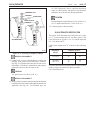
26-SI ALTERNATOR SPECIFICATION
The typical 26-SI Alternator rotor field check at 12-volts
is 3.0 - 4.3 current amps and 2.8 - 4.0 ohms @ 80o F. The
rotor field check at 24 volts is 2.0 - 2.8 current amps and
8.5 - 12.0 ohms at 80o F.
ALTERNATOR
Cold Current output at 80o F is shown in the following
table.
26-5053
Figure 54. Connecting to Output Terminal
INSTALL OR CONNECT
11. Ground lead, if used, to ground hole in rectifier end
housing, with ground screw/lockwasher assembly.
(See Fig. 53) If ground lead is not used, be sure screw/
lockwasher is installed in ground hole and properly
tightened to prevent entry of water or dirt.
TIGHTEN
1/4" ground screw to 6 N.m (55 lb. in.).
INSTALL OR CONNECT
12. Battery cable to output terminal, using insulated output
terminal bolt or lock washer and output terminal nut as
applicable. (See Fig. 54) For insulated type, use
Alternator
Model
Amperes @ 80o F
1800 rpm
5000 rpm
12V/85A
56
85
24V/50A
24V/75A
33
45
50
75
For further information on rotations and exact specification
number on these or other Delco Remy Products:
Call 1-800-DRA-0222
PAGE
28
1G-287
26-SI ALTERNATOR
4/96
SERVICE PARTS
Illus.
No. Name
1.
2.
3.
4.
5.
6.
7.
8.
9.
10.
11.
12.
13.
14.
15.
16.
17.
18.
19.
20.
21.
22.
23.
24.
25.
26.
27.
28.
29.
30.
31.
Housing, Rectifier End
Bearing, Rectifier End Outer Race
Bearing, Rectifier End Inner Race
Rotor Assembly
Stator Assembly
Frame, Drive End (DE)
Bearing, DE
Field Coil and Support
Regulator
Diode, In Frame
Diode, Heat Sink
Heat Sink
Stud Package, Diode Junction
Heat Sink Assembly
Diode Trio Assembly
Terminal, Output (Male)
Terminal Pkg., Output (Female)
Terminal Pkg., “R” or “I”
Cover, Rectifier End
Plate, Rectifier End
Retainer Plate, DE
Collar, DE (Inside)
Fan
Lock Washer, Ground Screw
Nut, Diode Trio to Stator Lead Attachment
Nut, Regulator Stud
Nut, Shaft
Screw, DE Bearing Retainer Attachment
Screw, Field Coil and Support Attachment
Screw, Ground
Screw/Lockwasher, Diode Heat Sink Atch.
Qty.
1
1
1
1
1
1
1
1
1
3
3
1
3
1
1
1
1
1
1
1
1
1
1
1
3
1
1
4
3
1
4
Illus.
No. Name
32.
33.
34.
35.
36.
37.
38.
39.
40.
41.
42.
43.
44.
45.
46.
47.
48.
49.
50.
51.
52.
53.
54.
55.
56.
57.
Qty.
Screw/Lockwasher, Rect. Covr. Atch. (3/4")
Screw/Lockwasher, Rect. Covr. Atch. (1 3/8")
Screw/Lockwasher, Rect. End Plate Atch.
Screw/Lockwasher, Regulator Atch. (Ground)
Screw/Lockwasher, Regulator Atch. (Insul.)
Screw/Lockwasher, Mounting Plate Atch.
Screw/Lockwshr, Diode Trio Assembly Atch.
Washer, Diode Heat Sink Attachment Screw
Washer, Diode Trio Assembly Attachment
Washer, now included with #37
Washer, Shaft Nut
Bolt, Thru
Bushing, Mounting Hinge (Rect. Hsg.)
Cap, Relay Terminal Insulating
Clip, Terminal (Stator Leads)
Gasket, Rectifier End Cover
Grommet, Stator Leads
Grommet, Field Coil Assembly
Insulation, Diode Heat Sink to Rect. Hsg.
Insulator, Diode Heat Sink Atch. Screw
Insulator, Stator Lead Grommet
Lead, Regulator Stud to Diode Heat Sink
Plate, Regulator Mounting
Plug, Expansion (Rectifier Housing)
Plug, Pipe (Rectifier Housing)
Support, Regulator Lead
Miscellaneous (not shown):
Capacitor, Radio Suppression
Lead Assembly, Indicator Light
3
4
4
1
2
1
1
4
1
1
1
4
1
1
3
1
1
1
1
4
1
1
1
1
1
1
26-SI ALTERNATOR
1G/287
PAGE
4/96
29
34
46
20
52
48
33
32
5
19
29
49
47
8
31
14
35
26
39
36
11
53
25
4
38
37
9
40
51
13
41
25
55
21
12
57
22
10
15
16
7
17
30
24
6
45
50
18
56
1
43
28
44
2
3
23
42
27
26-5054
PAGE
1G-287
26-SI ALTERNATOR
4/96
Delco Remy International, Inc.
2902 Enterprise Drive
Anderson, IN 46013
For further information and specifications on these and other
Delco Remy Products call: 1-800-DRA-0222
© Copyright DRI, 1G-500 10/97
Delco Remy is a registered trademark licensed by General Motors Corporation.