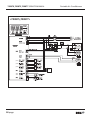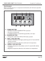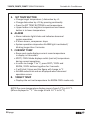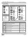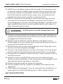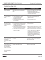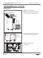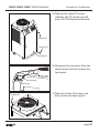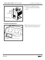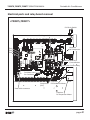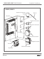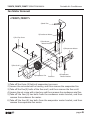
1
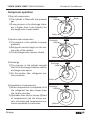
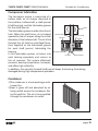
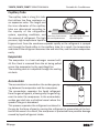
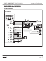
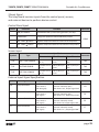
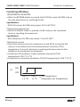
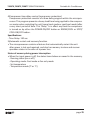
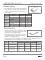
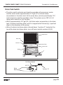
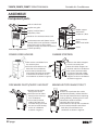
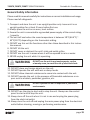
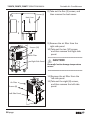
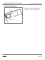
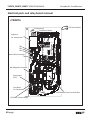
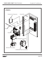
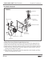
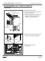
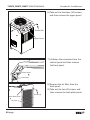
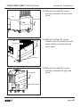
IDEAL AIR
Portable Air Condioners
Models: 700870,700875,700877
SERVICE MANUAL
700870,700875,700877 SERVICE MANUAL
Portable Air Condioners
Table of Contents
GENERAL DESCRIPTION....................................................................................4
General air conditioning system
Portable air conditioning system
SPECIFICATIONS..................................................................................................5
Exterior Dimension Diagram
Technical Speciications
Characteristics
CONSTRUCTION...................................................................................................9
Internal Structure
REFRIGERANT SYSTEM CONSTRUCTION..................................................12
Compressor
Compressor lubrication
Condenser
Capillary Tube
Evaporator
Accumulator
ELECTRICAL SYSTEM.......................................................................................17
Circuit Diagram
Control panel
Program Setting
Controller Board
Control Speciications
Self-Diagnostic Codes
Compressor
Evaporator Fan Motor
Condenser Fan Motor
Capacitor
Molded Case Circuit Breaker
Magnetic Contact
Thermal Relay
Temperature Thermistor
Drain Tank Switch
2 page
700870,700875,700877 SERVICE MANUAL
Portable Air Condioners
ASSEMBLY...........................................................................................................32
Component parts
General Safety Information
Troubleshooting chart
DISASSEMBLY (For 700870).........................................................................36
Disassembly
Control panel removal
Electrical parts and relay board removal
Fan motor removal
DISASSEMBLY (For 700875,700877).........................................................43
Disassembly
Control panel removal
Electrical parts and relay board removal
Fan motor removal
REFRGERANT SYSTEM REPAIR....................................................................50
Brazing
Removal of Refrigerant System Components
Charging the System with R-410A Refrigerant
Refrigerant Charging Work
page 3
700870,700875,700877 SERVICE MANUAL
Portable Air Condioners
GENERAL DESCRIPTION
General air condioning system
1) convenonal air condioners cool the enre enclosed environment.
2) They act as “heat exchangers”, equiring an interior unit (evaporator) to blow
cool air into the interior and an exterior unit (condenser) to exhaust exchanged
heat to the outdoors.
Outdoor Unit
Indoor Unit
Condenser
Evaporator
Portable air condioning system
1) The 700870 / 700875 / 700877 is a spot
cooler which directs cool air to parcular
areas or objects.
2) The 700870 / 700875 / 700877 has the
following features.
3) The innovave design of the 700870
/ 700875 / 700877 has resulted in one
compact unit, replacing the need for two
separate units.
4) With the whole cooling system built into
one compact unit, the 700870 / 700875
/ 700877 requires no piping and can be
easily transported and installed.
5) The 700870 / 700875 / 700877 is economical because it cools only the area or
objects which need to be cooled.
4 page
Exhaust Hot Air
Filter
Cooling Air
Filter
Intake air
(to Condenser)
Intake air
(to Evaporator)
700870,700875,700877 SERVICE MANUAL
Portable Air Condioners
SPECIFICATIONS
Exterior Dimension Diagram
<700870>
20
5.9
5.6
4
36.2
36.2
2.9
12.5
12
13.1
17.5
19.8
page 5
700870,700875,700877 SERVICE MANUAL
Portable Air Condioners
<700875>
7.8
5.9
7.1
16.3
4.8
36.4
42.1
5.6
1.9
20
16.3
17.3
22.1
6 page
24.4
700870,700875,700877 SERVICE MANUAL
Portable Air Condioners
<700877>
22.1
6.2
6.2
4.7
5.9
16.3
36.4
42.1
5.6
1.9
20
4.8
4.7
16.3
17.3
22.1
24.4
page 7
700870,700875,700877 SERVICE MANUAL
Portable Air Condioners
Technical Specificaons
Specifications
Cooling Capacity
Unit
700870
700875
700877
Btu/h
13,200
19,500 / 21,000
28,000 / 29,000
Phase
Single
Single
Single
208 / 230
Volts
115
208 / 230
Hertz
60
60
60
Power Consumption
Watts
1,300
2,300
3,100
Rated Current
Amps
Toshiba LG
11.5 10.9
11.0 / 10.0
15.0 / 14.0
EER
Btu/Wh
8.6
8.9
9.3
Circuit Breaker Size
Amps
15
15
20
Nema Plug
Type
5-15P
6-15P
6-20P
Power Cord Gauge
Awg
14
14
12
Power Cord Length
ft
10
6
6
Dimensions (W x H x D)
In.(mm)
Weight (Net / Gross)
Lbs(kg)
17.5 x 54.9 x 19.9
(445 x 1395 x 505)
132 / 145.5
(60 / 66)
22.0 x 62 x 24.4
(560 x 1575 x 620)
198 / 216
(90 / 98)
22.0 x 62 x 24.4
(560 x 1575 x 620)
209 / 227
(95 / 103)
3.17 (12)
3.17 (12)
3.17 (12)
Power Supply
Condensate tank
Gallons(Liters)
No. of Cool Air Outlets
Pcs
1
2
3
Ambient temperature range
F( C)
64~113 (18~45)
64~113 (18~45)
64~113 (18~45)
Setting temperature (Room cool mode)
F( C)
64~86 (18~30)
64~86 (18~30)
64~86 (18~30)
Setting temperature (Spot cool mode)
F( C)
32~86 (0~30)
32~86 (0~30)
32~86 (0~30)
ft²(m²)
377 (35)
527 (50)
743 (70)
Type
R-410A
Application Area (Room cool mode)
Refrigerant
Toshiba
LG
15.9 (451) 15.5 (440)
Toshiba
LG
Psig
450 / 250 450 / 270
283
/
247
CFM(CMH)
(480 / 420)
pcs
4
oz(g)
Design Pressure - Hi/Low
Indoor Air Flow (High/Low)
Wheels
Hot Air Duct Diameter
Maximum Duct Length
R-410A
R-410A
42.3 (1200)
39.9(1130)
450 / 250
450 / 280
512 / 477
(870 / 810)
583 / 547
(990 / 930)
4
4
diameter
76mm
102mm
102mm
In.(mm)
12 (300)
16 (400)
16 (400)
ft(m)
16 (5)
30 (9)
30 (9)
Safety Devices
Compressor overload protector, Anti-freezing thermister, Full drain tank switch,
Autometic restart (Power interruption), Compressor time delay program,
High pressure switch
Features
Temperature control, Self-diagnostic function, Two sppeds fan, Optional drain
pump kit, Washable filters, F( C) display
* Specifications are subject to change without notice.
8 page
700870,700875,700877 SERVICE MANUAL
Portable Air Condioners
CONSTRUCTION
Internal Structure
<700870>
Condenser Air Outlet
Condenser Motor
Eva Scroll
Condenser
Evaporator Motor
Evaporator
Control Box
• Relay Board
• Capacitor
Control Panel
Drain Tank
Drain Tank Switch
Caster (Rear)
Compressor
Cooling Air Duct
Locking Swivel Caster
page 9
700870,700875,700877 SERVICE MANUAL
Portable Air Condioners
<700875>
Cooling Air Duct
Condenser Air Outlet
Condenser Motor
Control Panel
Condenser
Evaporator Motor
Eva Scroll
Control Box
• Relay Board
• Capacitor
Drain Tank
Evaporator
Drain Tank Switch
Caster (Rear)
Compressor
Locking Swivel Caster
10 page
700870,700875,700877 SERVICE MANUAL
Portable Air Condioners
<700877>
Cooling Air Duct
Condenser Air Outlet
Condenser Motor
Control Panel
Condenser
Evaporator Motor
Eva Scroll
Evaporator
Control Box
• Relay Board
• Capacitor
Drain Tank
Drain Tank Switch
Caster (Rear)
Compressor
Locking Swivel Caster
page 11
700870,700875,700877 SERVICE MANUAL
Portable Air Condioners
REFRIGERANT SYSTEM CONSTRUCTION
<700870,700875,700877>
Condenser Air Outlet
Flow of
Refrigerant
Condenser Motor
Condenser
Compressor
Evaporator
Capillary tube
Accumulator
Drier
12 page
700870,700875,700877 SERVICE MANUAL
Portable Air Condioners
Compressor
The construcon of a rotary type compressor is divided into two mechanisms;
the drive mechanism (compressor motor), and the compression mechanism
(compressor). When the rotor sha of the motor (drive mechanism) turns, the
roller (compression mechanism) rotates to compress the refrigerant.
To Condenser
From Evaporator
Accumulator
Terminal
Strainer
Stator
Rotor
Cylinder
Roller
Blade
Discharge Valve
Lubricator
Oil
page 13
700870,700875,700877 SERVICE MANUAL
Portable Air Condioners
Compressor operaon
1) Start of compression
1) The cylinder is filled with low pressure
gas.
2) Since pressure in the discharge chamber is higher than in the cylinder, the
discharge valve is kept closed.
Discharge
Valve
Blade
Roller
2) Sucon and compression
1) The pressure in the cylinder increases
gradually.
2) Refrigerant sucon begins on the sucon side of the cylinder.
3) The discharge valve remains closed.
Discharge
Valve
Blade
Roller
3) Discharge
1) The pressure in the cylinder exceeds
that in the discharge chamber, and the
discharge valve opens.
2) On the sucon side, refrigerant sucon connues.
Discharge
Valve
Blade
Roller
4) Compleon of compression
1) When compression is completed, all of
the refrigerant has been drawn from
the sucon chamber.
2) Operaon then returns to step 1)(Start
of compression) and the above process of sucon and compression connues repeatedly in succession.
14 page
Discharge
Valve
Blade
Roller
700870,700875,700877 SERVICE MANUAL
Portable Air Condioners
Compressor lubricaon
The lubricaon system is comprised of a
hollow sha, an oil scraper mounted at
the end face, hollow sha, a sha journal
(sha bearing), and the lubricaon groove
Rotor
for the sha journal.
The lubricaon groove is wider than the oil
hole. When the sha turns, oil is scraped
Hollow Sha
Eccentric Sha
upward by the oil scraper along the inside
Cylinder
Roller
diameter of the hollow sha. The oil is fed
through the oil hole by centrifugal force,
then supplied to the lubricaon groove
for each sha journal, lubricang the
Oil Feed Groove
bearing.
In this lubricaon system, oil enters into
Oil Scrapper
Oil Hole
each bearing separately and returns to
the oil reservoir. This system effecvely
prevents bearing temperature increases,
and offers high reliability.
In addion, the specially treated sha journal keeps the bearing from being
damaged during high temperature operaon.
Condenser
1)The condenser is a heat exchanger with
Louver fins.
2)Heat is given off and absorbed by air
being pulled across the condenser fins
by the axial fan. The air is then expelled
through the condenser air outlet.
page 15
700870,700875,700877 SERVICE MANUAL
Portable Air Condioners
Capillary Tube
The capillary tube is a long thin tube
that ulizes line flow resistance as
an expansion valve. The length and
the inner diameter of the capillary
tube are determined according to
the capacity of the refrigeraon
system, operang condions, and Low Temp./Low Pressure High Temp./High Pressure
Liquid Refrigerant
the amount of refrigerant. The high Gas and Liquid Mixture
pressure, high temperature liquid refrigerant sent from the condenser expands rapidly as the refrigerant is sprayed
out through the fixed orifice in the capillary tube. As a result, the temperature
and state of the refrigerant becomes low and mist-like, and therefore evaporates
easily.
Evaporator
The evaporator is a heat exchanger covered with
slit fins. Heat is removed from the air being pulled
across the evaporator by the centrifugal fan.
The resulng cool air is expelled through the cooling
air ducts.
Accumulator
The accumulator is mounted on the sucon gas pipFrom Evaporator
ing between the evaporator and the compressor.
The accumulator separates the liquid refrigerant
from the gas refrigerant, allowing only the gas refrigerant to enter the compressor. In the accumulator,
sucon gas isled into a cylindrical vessel where the
speed of the gas is decreased.
To Compressor
This process separates the refrigerant contained in
the gas by the force of gravity, causing the refrigerant to accumulate at the bottom of the vessel. As a result, the compressor is protected from possible damage
caused by liquid refrigerant intake.
16 page
700870,700875,700877 SERVICE MANUAL
Portable Air Condioners
ELECTRICAL SYSTEM
Circuit Diagram
<700870>
(TH1)
(TH2)
(TH3)
DRAIN
PUMP
page 17
700870,700875,700877 SERVICE MANUAL
Portable Air Condioners
<700875,700877>
(TH1)
(TH2)
(TH3)
DRAIN
PUMP
18 page
700870,700875,700877 SERVICE MANUAL
Portable Air Condioners
Control panel
Before operang the unit, it is important to be familiar with the basic operaon
of the control panel.
7
1
8
2
5
3
6
4
1. POWER BUTTON
• Acvates unit when POWER BUTTON is pressed.
• Fan starts on low speed.
• If POWER BUTTON is pressed during operaon, unit stops.
2. BLOWER BUTTON
• Changes fan speed from LOW to HIGH when pressed.
3. SPOT / COOL BUTTON
• Acvates compressor and begins producing cool air 5 seconds aer
buon is pressed.
• Regulates temperature based on outlet cool air temperature.
4. ROOM / COOL BUTTON
• Acvates compressor and produces cool air 5 seconds aer buon
is pressed.
• Regulates temperature based on inlet ambient air temperature.
page 19
700870,700875,700877 SERVICE MANUAL
Portable Air Condioners
5. SET TEMP BUTTON
• Change target temperature / data value by ± 1.
• Change data value by ± 10 by pressing connually.
• Press the SET TEMP BUTTONS to set temperature.
• Upper buon is to heighten temperature and Lower
buon is to lower temperature.
6. ALARM
• Alarm indicator light blinks and indicates abnormal
system operaon.
• If Alarm occurs, compressor stops.
• System operaon stops when ALARM light is acvated /
blinking longer than 3 minutes.
7. CURRENT TEMP
• Room cool mode displays current room temperature
in display in Fahrenheit.
• SPOT / COOL Mode displays outlet (cool air) temperature
during normal operaons.
• In order to change °F to °C, press SPOT / COOL and
ROOM / COOL buons together for 2 seconds.
• C will blink 2 mes and the figure will change to °C
• ALARM codes blink and are displayed when abnormal
operaon occurs.
8. TARGET TEMP
• Displays the unit set temperature for ROOM COOL mode only.
NOTE:The room temperature display range is from 14 °F to 122 °F.
(When displayed in “°C ” the range is from -10 °C to 50 °C)
20 page
700870,700875,700877 SERVICE MANUAL
Portable Air Condioners
Program Seng
Temperature Seng
Program Seng (Auto restored when no seng is made in each mode)
Keep
depressing
more than
3 seconds
Temperature
dependence
Delay me
Change
Change
Change
Target
Temperature
Power Switch
Deviaon
temperature
seng
Change
IC temperature
seng
Change
ON/OFF when keep
depressing more than
1 seconds
Auto restored when no seng is made in each mode
Indicaon
Descripon
Delay me seng of COMP operaon.
EX)If seng is 3mins, it takes 3mins to
be ON aer COMP is OFF.
Deviaon temp seng.
Ex)It operates between 30 c to 34 c( ±2 c),if dF seng is
2 c under 32 c( temp seng).
the range of seng
1-5minutes, control is
available per 1 minute
1c~5c
Temperature Correcon
-10 c ~ +10 c
Temperature Correcon
-10 c ~ +10 c
IC temperature seng
(Frost prevenon sensor)
-5 c ~ +5 c
page 21
700870,700875,700877 SERVICE MANUAL
Portable Air Condioners
Relay Board
The relay board contains the compressor and fan on relays, in addion to
a step-down transformer that converts the line voltage (700870: 115 VAC,
700875: 208/230, 700877: 208/230 VAC) to 12V. This voltage is then converted
from AC to DC and used for relay coil acvaon. The 12 V (DC) power is sent to
the control panel assembly.
1)Power supply requirements
The 700870 requires a single-phase 115 V, 60 Hz power supply, while the
700875 / 700877 requires a single-phase 208/230 V, 60 Hz power supply.
2)Relay board fuse
The relay board fuse is the only serviceable component on the relay board
assembly. This fuse provides protecon against damage to the step-down
transformer. The fuse must be replaced with the exact same part, or a suitable
equivalent.
Specificaons : 3.15 A 250 VAC
CAUTION
22 page
Failure to use the exact same fuse may result in damage to the
unit and/or components, and will also void the unit warranty.
700870,700875,700877 SERVICE MANUAL
Portable Air Condioners
3)Input Signal
The relay board receives inputs from the control panel, sensors,
and external devices to perform device control.
Control Panel Input
Symbol
Indicaon
Funcon
Connector
ON/OFF Buon
If POWER BUTTON is pressed during operaon, unit stops.
FAN Buon
Changes fan speed from LOW to HIGH when pressed.
CON8
SET TEMP
Buon
Regulates temperature based on outlet cool air temperature.
SET TEMP
Buon
Regulates temperature based on inlet ambient air temperature.
Sensor Input
Symbol
Specificaon
Type
Connector
Characterisc "Short"Detecon "Open"Detecon
TH1
OUT TEMP SENSOR
10 k ohm at 77 °F
(25 °C)
181 °F (83 °C) or
more
-29 °F (-34 °C) or
less
TH1
TH2
IN TEMP SENSOR
10 k ohm at 77 °F
(25 °C)
181 °F (83 °C) or
more
-29 °F (-34 °C) or
less
TH2
TH3
ICE TEMP SENSOR
10 k ohm at 77 °F
(25 °C)
181 °F (83 °C) or
more
-29 °F (-34 °C) or
less
TH3
External Input Signal Specificaon
Symbol
Signal
Specificaon
Funcon
Connector
CO
Comp Overload
On: Between 10 to 20
mA at DC12 V
(Off: No signal)
On: Acvates “Defect control”
(Contact: Normally open)
LED shows “CO”, Output signal“ON”
CO
FU
External Pump Failure On: Between 10 to 20
mA at DC12 V
(Off: signal)
Off: Acvates “Defect control”
(Contact: Normally open)
LED shows “FU”, Output signal“ON”
FU
On: Between 10 to 20
mA at DC12 V
(Off: signal)
On: Acvates “Defect control”
(Contact: Normally closed):
LED shows “PS” output signal “ON”
PS
On: Between 10 to 20
mA at DC12 V
(Off: signal)
On: Acvates “Defect control”
(Contact: Normally closed)
LED shows “FT”, Output signal“ON”
FT
PS
FT
Pressure Switch
Tank Full Switch
page 23
700870,700875,700877 SERVICE MANUAL
Portable Air Condioners
Control Specificaons
1)EVAPORATOR FAN MOTOR
• When the BLOWER buon is pressed, the RL1/3 (fan motor HI/LOW) relay on
the relay board turns on, operang the fan.
Specificaons:
- RL1/3 (Fan motor HI-LOW) relay output: 10 A at AC 250 V
2)Compressor start control
• When the ON/OFF buon is pressed, the RL4 relay on the relay board
turns on, operang the compressor.
Specificaons:
- RL4 (Compressor On-Off) relay output: 5 A at AC 250 V
3)An-freeze control
• An-freeze controls turns the compressor on and off by turning the RL4
relay on in accordance with the freeze protecon thermistor (TH3)
temperature. As a result, decreases in cooling performance due to frost
buildup on the evaporator are prevented.
• Compressor off condions: Freeze protecon thermistor (TH3)
temperature ≤ 28.4 °F (-2 °C)
• Compressor on (recovery) condions: TH3 (ICE temperature) ≥ 33.8 °F (1 °C)
ON
C3
OFF
28.4 °F
(-2 °C)
24 page
33.8 °F
(1 °C)
TH3 temperature
(Evaporator out temperature)
700870,700875,700877 SERVICE MANUAL
Portable Air Condioners
4)Compressor me delay control (compressor protecon)
Compressor protecon consists of a me delay program within the microprocessor. This program prevents a heavy load from being applied to the compressor motor when restarng the unit (room/cool mode or spot/cool mode) aer
a very short period of me. This “delay” is in effect any me the compressor
is turned on by either the POWER ON/OFF buon or ROOM/COOL or SPOT/
COOL ON/OFF buon.
Specificaons:
- Time Delay: 120 sec.
5)Automac restart and recovery funcon
• The microprocessor contains a feature that automacally restart the unit
aer power is lost and regained, and also has memory to store and recover
operaon status in the even of a power loss.
Status of memory during power interrupon
• When the input power is off, the status items below are saved in the memory.
- Running status (on or off)
- Operang mode: Cool mode or fan only mode
- Set temperature
- Temperature mode (°F or °C)
page 25
700870,700875,700877 SERVICE MANUAL
Portable Air Condioners
6)Temperature control
• During cool mode, temperature control changes the RL4 (compressor on/off)
relay status according to TH3 temperature in the available range(-4 °F to 140
°F (-20 °C to 60 °C)).
ON
RL4
(Compressor Relay)
OFF
(Set Temp. -3 °F)
(Set Temp. -1.7 °C)
Set Temp
Inlet Air Temperature
When compressor operaon connues within this range
for more than 5 minutes, the RL4 relay stops.
26 page
700870,700875,700877 SERVICE MANUAL
Portable Air Condioners
Self-Diagnosc Codes
Self-diagnosc codes are displayed on the Display Panel under the following
condions.
Alarm Display
Problem
Cause
Correcve Acon
Frost prevenon
sensor and
Abnormal
temperature
sensor value
Indoor heat exchanger
temperature too low
TH3 temperature sensor
has a loose or broken
connecon
Do not use the air
condioner if ambient
temperature is lower than
18°C (64°F)
Contact a qualified service
agent
Refrigerant high
pressure switch
Blocked air filter
Blocked / kinked exhaust
duct
Ambient temperature
is too high
Clean air filter
Ensure exhaust duct is not
blocked / kinked
Do not use the air
condioner if ambient
temperature is higher than
45°C (113°F)
Abnormal
temperature
sensor value
TH1(Outlet) temperature
sensor has a loose or
broken connecon
Contact a qualified service
agent
Abnormal
temperature
sensor value
TH2(Inlet) temperature
sensor has a loose or
broken connecon
Contact a qualified service
agent
Compressor
overloaded
Ambient temperature is
too high
Unstable voltage supply
Defecve compressor
Do not use the air
condioner if ambient
temperature is higher than
45°C (113°F)
Contact a qualified service
agent
Replace compressor
Empty the water tank
Condensate
water level
alarm
Condensate tank is full
Drain pump
alarm
Drain pump defecve or
improper hose connecon
(including kink or blockage)
Aer installaon of the
water tank, press the SPOT/
COOL or ROOM/COOL
buon to resume operaon
Check the hose connecon
and hose
Replace drain pump
page 27
700870,700875,700877 SERVICE MANUAL
Portable Air Condioners
Compressor
1) Compressor motor
• The compressor motor is a single-phase motor
and is contained within the same housing as
the compressor.
Specificaons:
Rated Voltage
Rated Output
700870
115V
700875
208/230 V
2000W / 1980W
700877
208/230 V
2700W / 2715W ±5%
1175W ±5%
2) Compressor overload relay
• The compressor overload relay is used to protect the compressor motor.
The relay interrupts the flow of current when there is an overload condion
and, high temperature builds up in the compressor.
C
Inner protector
COMPR.
MOTOR
AUX
S
MAIN
R
Run capacitor
28 page
700870,700875,700877 SERVICE MANUAL
Portable Air Condioners
Evaporator Fan Motor
• The fan motor is a single phase, inducon type.
The motor rotates the fan.
• The following table shows the specificaons of
the fan motor used for each model.
NOTE:An internal overload relay is used to protect
the fan motor. This relay is built into the fan motor
and interrupts the flow of current when there is an
over current situaon, or if abnormally high
temperature builds up in the fan motor.
Condenser Fan Motor
• The fan motor is a single phase, inducon type.
The motor rotates the fan.
• The following table shows the specificaons of
the fan motor used for each model.
NOTE:An internal overload relay is used to protect
the fan motor. This relay is built into the fan motor
and interrupts the flow of current when there is an
over current situaon, or if abnormally high
temperature builds up in the fan motor.
page 29
700870,700875,700877 SERVICE MANUAL
Portable Air Condioners
Capacitor Capacitor
• The capacitor is used to improve the rotaonal
power of the fan motor and compressor at
start up. The specificaon for each capacitor is
shown below.
700870
700875
700877
Check capacitance
Capacitor
Rated Voltage
Capacitance
Compressor
Evaporator Fan Motor
Condenser Fan Motor
Compressor
Evaporator Fan Motor
Condenser Fan Motor
Compressor
Evaporator Fan Motor
Condenser Fan Motor
250 v
450 v
450 v
370 v
450 v
450 v
370 v
450 v
450 v
45uF
10uF
3.5uF
50uF
8uF
8uF
50uF
5uF
7uF
Temperature Sensor
• Outlet temp sensor (TH1) is installed on top of
the evaporator, and detects evaporator outlet
temperature as a resistance value.
• Inlet temp sensor (TH2) is installed in front of
evaporator, and detects evaporator inlet temperature as a resistance value.
• Ice temp sensor (TH3) is installed in the evaporator outlet piping, and detects
low temperature on the evaporator as a resistance value.
Symbol
Specificaon
Type
Connector
Characterisc "Short"Detecon "Open"Detecon
TH1
OUT TEMP SENSOR
10 k ohm at 77 °F
(25 °C)
181 °F (83 °C) or
more
-29 °F (-34 °C) or
less
TH1
TH2
IN TEMP SENSOR
10 k ohm at 77 °F
(25 °C)
181 °F (83 °C) or
more
-29 °F (-34 °C) or
less
TH2
TH3
ICE TEMP SENSOR
10 k ohm at 77 °F
(25 °C)
181 °F (83 °C) or
more
-29 °F (-34 °C) or
less
TH3
30 page
700870,700875,700877 SERVICE MANUAL
Portable Air Condioners
Drain Tank Switch
• The drain switch acvates and stop the operaon of compressor motor
and fan motor when approximately 3.17 gal (12 L) of drain water
accumulates in the drain tank. At the same me, control panel display “FL”,
and compressor and fan operaons stop. This system uses a 250 V, 0.1 A
rang micro switch for this funcon.
• When approximately 3.17 gal (12 L) of drain water accumulates in the drain
tank, the drain tank base plate, which is supported at fulcrum (a), is pushed
down in the direcon of the arrow.
• When the drain tank base plate is forced down, “poron A”, located at the
top of the drain tank base plate, turns off micro switch contacts (1)-(2).
Evaporator
Drain Pan
Poron “A”
Drain Tube
Drain Tank
Drain Water
Spring
a
Base Plate
Base
Full Drain Switch
NC (2)
Relay
Board
2
NC
1
NO 3
COM
Poron “A”
C (1)
page 31
700870,700875,700877 SERVICE MANUAL
Portable Air Condioners
ASSEMBLY
Component parts
Cool air outlet hose
Top fan wire grille
Rubber stopper
Side handle
Condenser / filter
Display / Control board
Evaporator / filter
Guide bar for condensate water tank
Condensate water tank (Water level is
sensed, and the unit operaon is stopped
when tank is full. An alarm will be
displayed. Empty the tank and replace to
resume operaon)
Front and Right Side View
Back and Left Side View
POWER CORD HOLDER
1.Take out the cord holder from
the accessory box.
2.Place the cord holder on the
back side of air condioner.
3.Use screws (enclosed inside
of accessory box with cord holder)
to install the cord holder on the
air condioner as shown in Figure 3.
DISCHARGE DUCTS/SUPPLY AIR DUCT
1.Remove cool air outlet
hose(s) from carton.
2.Place the cool air outlet
hose(s) on the front top
of air condioner.
3.Use screws (enclosed
inside of box with cool
air outlet hose(s) to install
the cool air outlet hose(s)
on the air condioner
as shown in Figure 5.
32 page
Electrical access
panel
Power cord holder
Caster
RUBBER STOPPERS
1.Take out the rubber stoppers
from the accessory box.
2.Place the rubber stoppers on
the back side of air condioner.
3.Use screws (enclosed inside
of accessory box with rubber
stoppers) to install the rubber
stoppers on the air condioner
as shown in Figure 4.
WARM AIR TOP EXHAUST DUCT
(Oponal)
A warm air top exhaust duct can be
purchased separately. Exhaust duct fits
over the top exhaust fan duct improving
cooling efficiency, allowing hot air to be
exhausted to another locaon.
1.Remove duct from carton.
2.Place duct on the top of air condioner.
3.Use screws (enclosed inside of box
with duct) to install duct on air
condioner as shown in Figure 6.
700870,700875,700877 SERVICE MANUAL
Portable Air Condioners
General Safety Informaon
Please read this manual carefully for instrucons on correct installaon and usage.
Please read all safeguards.
1. Transport and store the unit in an upright posion only. Leave unit in an
upright posion for at least 3 hours before first use.
2. Always place the unit on an even, level surface.
3. Ensure the unit is connected to a grounded power supply of the correct rang
/ capacity.
4. The unit will cool when the room temperature is between 18°C (64.4°F) ~
45°C(113°F) depending on the thermostat seng.
5. DO NOT use this unit for funcons other than those described in this instrucon manual.
6. DO NOT lt the unit.
7. DO NOT cover or obstruct the unit’s inlet and outlet grilles.
8. DO NOT use the unit in areas where it will be exposed to rain or water.
9. NEVER unplug the unit while it is operang.
WARNING
DO NOT use the unit in wet environments, such as
a laundry room, to avoid the risk of electrical shock.
10. DO NOT place any foreign objects on the unit.
11. DO NOT operate the unit with wet or damp hands.
12. DO NOT allow chemical substances to come into contact with the unit.
13. DO NOT operate the unit in the presence of flammable substances or vapors such as alcohols, pescides, gasoline, etc.
WARNING
DO NOT operate the unit in explosive or flammable
environments.
14. DO NOT use the plug to start and to stop the unit. Always use the control
panel to start and to stop the unit.
15. Always turn off the unit when it is not in use and unplug the power plug
from the electrical outlet.
16. Always turn the unit off and unplug the main power plug from the electrical
outlet before cleaning, moving or performing maintenance.
page 33
700870,700875,700877 SERVICE MANUAL
Portable Air Condioners
17. AVOID the use of adapter plugs or extension cords. If it is necessary to use
an extension cord or an adapter plug to operate the unit, ensure that they
are correctly rated for the applicaon. Consult a local qualified electrician
and all local electrical codes to ensure proper setup. Any extension cord
used with this device must be rated for a minimum of 15A.
18. DO NOT unplug the unit by pulling on the electrical cord. Keep electrical
cord away from heat sources and always completely unroll the cord to
avoid overheang. If the power cord becomes damaged, a qualified service
agent, qualified electrician, or similarly qualified person must replace it, in
order to avoid a hazard or shock.
WARNING
DO NOT operate a unit with a damaged power cord.
19. The filters must be used with the product at all mes. When the filters are
removed for cleaning, always ensure that the unit has been turned off and
unplugged from the electrical outlet.
20. Regularly clean the filters to maintain efficiency. If the filters are not
cleaned regularly, the units output performance and efficiency will decline
and energy consumpon will increase.
21. DO NOT operate the unit with a damaged power cord or plug, aer it malfuncons, has been dropped or damaged.
22. Only use in the upright posion on an even, flat surface. Unit must be posioned at least 24 inches (60 cm) from the nearest object in any direcon.
23. Stop operaon immediately if abnormal noise or odor is noced. Contact a
local service center.
24. Appliance is not to used by children or persons with reduced physical,
sensory or mental capabilies, or lack of experience and knowledge, unless
they have been given supervision or instrucon.
25. Children being supervised not to play with appliance.
26. That the appliance shall be installed in accordance with naonal wiring
regulaons.
27. If the supply cord is damaged, it must be replaced by the manufacturer, its
service agent or similarly qualified persons in order to avoid a hazard.
SAVE THESE INSTRUCTIONS
34 page
700870,700875,700877 SERVICE MANUAL
Portable Air Condioners
Troubleshoong chart
Symptom
Possible Cause(s)
Correcve Acon
Water leakage
High water level in condensate
tank
1. Remove blockage from drain hose
2. Remove any object stuck
undeerneath of the black panel
nuder the water tank
The unit doesn’t
work
1. Check the power supply
to verify that power is
available to the unit
2. Verify that the power cord
is connected
1. Reset the circuit breaker and
restart the unit
1. Ambient air cannot be properly
cooled if the filter is dirty and
not regularly cleaned
2. Compressor will not work if the
unit isturned off and on quickly.
3. The ambient air temperature
may be too high
1. Clean the filter
No cause
Common to hear coolant flowing
aer unit shuts off
No cold air flows
from the cold air
outlet
Water flow can be
heard aer
compressor shuts
off
Alarm displays “FT” Spring is possibly broken
with less than half
of condensate
water in the tank
2. Connect power cord
2. Wait 2 minutes aer unit is turned
off before turning the unit back on.
3. The temperature of the compressor
can be higher when the ambient
temperature is too high. The
compressor will not work unless
the ambient air temperature is
within the acceptable operang
range of the unit
Replace a new spring
Spring is possibly
broken
page 35
700870,700875,700877 SERVICE MANUAL
Portable Air Condioners
DISASSEMBLY (For 700870)
Disassembly
1) Remove the drain tank.
2) Take out the four (4) screws, and
then remove the cooling air duct.
Cooling Air Duct
Screws (4)
Drain Tank
3) Take out the three (3) screws, and
then remove the electric cover.
Screws (3)
electric cover
4) Off the circuit breaker.
(For safety)
Circuit Breaker
36 page
700870,700875,700877 SERVICE MANUAL
Portable Air Condioners
5) Take out the seven (7) screws.
Unfasten two (2) screws to a half
point. Pull the front panel forward.
Screws (7)
Screws (2)
Front Panel
6) Disconnect the connector from the
control panel and then remove the
front panel.
Control panel
Connector
Screws (5)
7) Take out the five (5) screws, and
then remove the upper panel.
page 37
700870,700875,700877 SERVICE MANUAL
Screws (5)
Portable Air Condioners
8) Take out the five (5) screws, and
then remove the back cover.
Back Cover
Screws (10)
Air Filter
Right Side Panel
9) Remove the air filter from the
right-side panel.
10) Take out the ten (10) screws,
and then remove the Right-side
panel.
CAUTION
Be careful not to damage temperature
sensor.
Air Filter
Screws (8)
Le Side Panel
38 page
11) Remove the air filter from the
le-side panel.
12) Take out the eight (8) screws,
and then remove the Le-side
panel.
700870,700875,700877 SERVICE MANUAL
Portable Air Condioners
Control Panel Removal
Screws (4)
1) Take out the four (4) screws, and
then remove the control panel.
Control Panel
page 39
700870,700875,700877 SERVICE MANUAL
Portable Air Condioners
Electrical parts and relay board removal
<700870>
(Compressor)
Condenser Motor
Full Drain Switch
(S)(C)
(R)
Capacitor
For Compressor
TH1
TH2
TH3
Data Cable Connector
MC:Magnec Contactor
Compressor
(R-C)
Fan Motor
for Condenser
MCCB:Mold Case Current Braker
OCR:Over Current Relay
40 page
700870,700875,700877 SERVICE MANUAL
Portable Air Condioners
<700870>
Capacitor for Compressor
Control Box
Stand-Off
Cable Tie
Relay Board
MC:Magnec Contactor
OCR:Over Current Relay
MCCB:Mold Case Current Braker
page 41
700870,700875,700877 SERVICE MANUAL
Portable Air Condioners
Fan Motor Removal
<700870>
4)Axial Fan
5)Condenser Motor
1)Eva Top Cover
5)Condenser
Motor Bracket
6)Evaporator Motor
6)Evaporator
Motor Bracket
2)Evaporator Fan
Paron
3)Eva Scroll
1) Take off the three (3) bolts of evaporator top cover.
2) Loosen the set screw with a hex key, and then remove the evaporator fan.
3) Take off the five (5) bolts of the Eva scroll, and then remove the Eva scroll.
4) Loosen the set screw with a hex key, and then remove the condenser axial fan.
5) Take off the four (4) hex bolts from the condenser motor bracket, and then
remove the condenser fan motor.
6) Take off the four (4) hex bolts from the evaporator motor bracket, and then
remove the evaporator fan motor.
42 page
700870,700875,700877 SERVICE MANUAL
Portable Air Condioners
DISASSEMBLY (For 700875,700877)
Disassembly
Cooling Air Duct
Screws (12)
1) Remove the drain tank.
2) Remove two (2) support lines and
remove front panel.
3) Take out the twelve (12) screws, and
then remove the cooling air duct.
(700875 : eight (8) screws)
Drain Tank
Front Panel
4) Take out the three (3) screws, and
then remove the service panel.
Service Panel
Screws (3)
5) Off the circuit breaker.
(For safety)
Circuit Breaker
page 43
700870,700875,700877 SERVICE MANUAL
Portable Air Condioners
6) Take out the fourteen (14) screws,
and then remove the upper panel.
Screws (14)
Upper Panel
7) Unfasten the connector from the
control panel and then remove
the front panel.
Control panel
Connector
8) Remove the air filter from the
back panel.
9) Take out the two (2) screws, and
then remove the back plate panel.
Back Plate Panel
Air Filter
44 page
Screws (2)
700870,700875,700877 SERVICE MANUAL
Portable Air Condioners
10) Take out the eight (8) screws,
and then remove the back cover
panel.
Back Cover Panel
Screws (8)
Screws (4)
Low Cover Panel
11) Take out the four (4) screws.
Unfasten two (2) screws to a half
point and then remove the low
cover panel.
Screws (2)
Screws (8)
12) Take out the eight (8) screws,
and then remove the right-side
panel.
Right Side Panel
page 45
700870,700875,700877 SERVICE MANUAL
Portable Air Condioners
13) Take out the eight (8) screws,
and then remove the le-side
panel.
Screws (8)
Le Side Panel
Control Panel Removal
1) Take out the four (4) screws, and
then remove the control panel.
Screws (4)
Control Panel
46 page
700870,700875,700877 SERVICE MANUAL
Portable Air Condioners
Electrical parts and relay board removal
<700875,700877>
Full Drain Switch
MC : Magnec Contactor
(Compressor)
(R)
(S)
(C)
Capacitor
for Compressor
TH1
TH2
TH3
MCCB: Mold case
Current Braker
OCR: Over Current Relay
Fan Motor
for Condenser
Compressor
(R-C)
Capacitor
for Condenser Motor
Data cable connector
Capacitor
for Evaporator Motor
page 47
700870,700875,700877 SERVICE MANUAL
Portable Air Condioners
<700875,700877>
Capacitor for Compressor
Cable Tie
Control Box
Capacitor for Eva motor
Capacitor for Cond motor
MCCB:Mold Case Current Braker
MC:Magnec Contactor
Stand-Off
OCR:Over Current Relay
Relay Board
48 page
700870,700875,700877 SERVICE MANUAL
Portable Air Condioners
Fan Motor Removal
<700875,700877>
4)Axial Fan
5)Condenser Motor
1)Eva Top Cover
5)Condenser
Motor Bracket
6)Evaporator Motor
3)Eva Scroll
2)Evaporator Fan
Paron
6)Evaporator
Motor Bracket
1) Take off the three (3) bolts of evaporator top cover.
2) Loosen the set screw with a hex key, and then remove the evaporator fan.
3) Take off the five (5) bolts of the Eva scroll, and then remove the Eva scroll.
4) Loosen the set screw with a hex key, and then remove the condenser axial fan.
5) Take off the four (4) hex bolts from the condenser motor bracket, and then
remove the condenser fan motor.
6) Take off the four (4) hex bolts from the evaporator motor bracket, and then
remove the evaporator fan motor.
page 49
700870,700875,700877 SERVICE MANUAL
Portable Air Condioners
REFRIGERANT SYSTEM REPAIR
Brazing
• In the event of a leak, obstrucon, or trouble in the refrigerant system of the
unit, replace or repair the defecve component. Aer replacing defecve component, braze all connecons.
1) Proper brazing techniques
• When brazing, use a slightly reduced flame. Oxyacetylene is commonly used
since the flame condion can be easily judged and adjusted. Unlike gas welding, a secondary flame is used for brazing. Properly preheat the base metal
according to the shape, size and thermal conducvity of the brazed fing.
• The most important point in flame brazing is to bring the enre brazed fing
to a proper brazing temperature. Care should be taken not to cause overflow
of the brazing filler metal, oxidaon of the brazing filler metal, or filler metal
deterioraon due to overheang the flux.
50 page
a
Clearance
0.001~0.003 in
(0.025~0.075 mm)
a
2) Brazed fings and fing clearance
• In general, the strength of the brazing filler
metal is lower than that of the base metal.
As such, the shape and clearance of brazed
fings are very important. Concerning the
shape of brazed fings, adhesive area
must be maximized. In addion, the clearance of the brazed fing must be minimized so that the brazing filler metal will
flow into the fing via capillary acon.
Clearance From The Pipe Fing and Tubing.
700870,700875,700877 SERVICE MANUAL
Portable Air Condioners
3) Cleaning brazing filler metal and piping
• When the refrigerant system has been opened, exposure to heat may cause
the brazing filler metal to sck to the inside and outside of the piping. Brazing
filler metal may also combine with oxygen in the air to form an oxide film. In
addion, grease and oils may sck to the pipe during handling. All these factors
will reduce the effecveness of brazing. Therefore, excess brazing filler metal
must be removed with sand paper, and by thorough cleaning with a solvent
such as Trichlene.
4) Dry Nitrogen gas use
• During brazing, the inside of the pipe undergoes an oxidave reacon due to
the brazing flame. Introduce dry nitrogen gas (0.3 gal/min (1 L/min); adjust
with the flow regulator) through the pinch-off tube of the refrigerant cycle to
prevent oxidaon.
NOTE:Do not get foreign maer such as dirt, water, or oil into the piping.
5) Vercal joints
• For vercal joints, heat the enre brazed
fing to the proper brazing temperature.
Bring the brazing filler metal into contact
with the fing so that the brazing filler
metal begins to flow.
• Stop heang the fing as soon as the
brazing filler metal has flown into the gap
(clearance). Since the brazing filler metal
flows easily into porons heated to the
proper temperature, the enre fing
must be kept at the proper brazing temperature.
45°
Vercal Down Joint
Brazing Filler Metal
Burner
Tube
Vercal Up Joint
Tube
45°
Burner
Brazing Filler Metal
page 51
700870,700875,700877 SERVICE MANUAL
Portable Air Condioners
Charging the System with R-410A Refrigerant
• Always ensure that the refrigerant system has been properly evacuated before
charging with the specified amount of R-410A.
• Equipments is only for R-410A.
• Liquid charge (no gas charge).
• Make sure not to use more than 90 % of the inial weight of R-410A in the
cylinder.
WARNING
•When handling refrigerant (R-410A), the following precauons should
always be observed:
- Always wear proper eye protecon while handling refrigerant.
- Maintain the temperature of the refrigerant container below 104 °F (40 °C).
- Perform repairs in a properly venlated area. (Never in an enclosed environment.)
- Do not expose refrigerant to an open flame.
- Never smoke while performing repairs, especially when handling refrigerant.
- Be careful the liquid refrigerant does not come in contact with the skin.
• If liquid refrigerant strikes eye or skin:
- Do not rub the eye or the skin.
- Splash large quanes of cool water on the eye or the skin.
- Apply clean petroleum jelly to the skin.
- Go immediately to a physician or to a hospital for professional treatment
52 page
700870,700875,700877 SERVICE MANUAL
Portable Air Condioners
Connecon of gauge manifold
1) Connect the charging hoses (low pressure
side) for the gauge manifold to the tube
fing.
Tube Fitting
NOTE:Connect the hoses using care not to
mistake the high pressure side for the
low pressure side and vice versa.
2) Connect the charging hose at the center of
the gauge manifold to the vacuum pump.
Low Pressure
Valve (Closed)
High Pressure Valve
(Closed)
Tube Fitting
Low Pressure
Side Tube
Vacuum Pump
(when stopped)
Evacuaon
1) Open the high pressure valve (LOW) of
Low Pressure Gauge
30 inHg (100 kPa) or larger
the gauge manifold.
High Pressure Gauge
2) Turn on the vacuum pump to start evacuaon.(Evacuate the system for approxi- Low Pressure
High Pressure Valve
Valve
mately 30 min.)
3) When the low pressure gauge indicates 30
Low Pressure
Side Tube
inHg(100 kPa), turn off the vacuum pump
Vacuum Pump
and close the Low pressure valves of the
(when stopped)
gauge manifold.
4) Leave the high pressure valve and the
lowpressure valve of the gauge manifold closed for five min or more, and confirm that the gauge pointer does not return to zero.
page 53
700870,700875,700877 SERVICE MANUAL
Portable Air Condioners
Refrigerant Charging Work
Refrigerant
Cylinder R-410A
Refrigerant charging
of
Low Pressure Valve
1) Remove the charging hose from the vacu- Valve
Refrigerant
um pump, and connect it to the refriger- Cylinder
ant cylinder (R-410A).
2) Loosen the nut on the gauge manifold
side of the charging hose. Open the valve
of the charging hose. Open the valve of
Low Pressure
the refrigerant cylinder. Aer air purging,
Side Tube
ghten this nut and close the valve of the
refrigerant cylinder.
3) Securely place the refrigerant cylinder on a scale with a weighing capacity of
70 lb (30 kg) that is graduated by 0.2 oz (5 g).
4) Open the high pressure valve of the gauge manifold and the valve of the refrigerant cylinder. Charge the system with refrigerant to the specified amount.
Standard Amount of Refrigerant:
- 700870: Toshiba 15.9 oz (451 g), LG 15.5 oz (400 g)
- 700875: 42.3 oz (1200 g)
- 700877: 51.8 oz (1470 g)
CAUTION
The amount of refrigerant charged has a great effect on the cooling capacity of the unit. Charge to the
specified amount,always observing the scale graduaons while charging.
5) Close the high pressure valve of the gauge manifold and the valve of the
refrigerant cylinder.
WARNING
•Do not aempt any repair on a charged system.
WARNING
•Before checking for gas leaks, fully confirm that there is nothing flammable
in the area to cause an explosion or fire. Contact of refrigerant with an
open fire generates toxic gas.
54 page