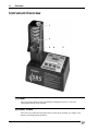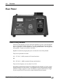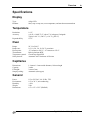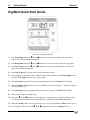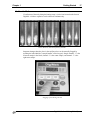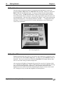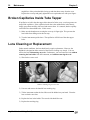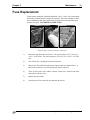
1
Operation and Service Manual
MPA160 and MPA161
DigiMelt
Student Melting Point
System
Stanford Research Systems
Revision 1.9 (September 2009)
Certification
Stanford Research Systems certifies that this product met its published specifications at the time
of shipment.
Warranty
This Stanford Research Systems product is warranted against defects in materials and
workmanship for a period of one (1) year from the date of shipment.
Service
For warranty service or repair, this product must be returned to a Stanford Research Systems
authorized service facility. Contact Stanford Research Systems or an authorized representative
before returning this product for repair.
Information in this document is subject to change without notice.
Copyright © Stanford Research Systems, Inc., 2009. All rights reserved.
Stanford Research Systems, Inc.
1290-C Reamwood Avenue
Sunnyvale, California 94089
408-744-9049
www.thinksrs.com
Printed in U.S.A.
DigiMelt Student Melting Point System
Safety and Preparation for Use
i
Safety and Preparation for Use
CAREFULLY READ THE IMPORTANT SAFETY INSTRUCTIONS AND NOTES
INCLUDED IN THIS SECTION BEFORE USING THE DIGIMELT STUDENT
MELTING POINT SYSTEM.
Within this section, the word 'product' specifically refers to the DigiMelt Student
Melting Point System.
This product is designed and built for use in teaching laboratories. It is intended to be
used to determine melting temperatures and melting ranges between ambient and 260°C
temperatures.
Though long experience has proven melting point instrumentation to be remarkably safe,
hazards are always associated with analytical equipment. The most effective way to
minimize risk to yourself and others is to read and follow all safety instructions.
Safety Instructions and Warnings
•
SAFETY PAYS! Safety instructions must be strictly followed during all stages of
installation, operation and service of this product. Failure to comply with these
precautions and warnings violates the safety standards expected of users of this
product.
•
This manual is a component of the product and must remain readily available to all
laboratory personnel with access to the product.
•
If you have any doubts about how to use this product safely, contact Stanford
Research Systems using the contact information provided in this manual (see inside
cover).
•
Do not use this product for any purpose other than its intended usage.
•
Retain these safety and operating instructions for future reference.
•
Identify and adhere to all warnings posted on the product and throughout this manual.
•
Failure to comply with these instructions may result in serious personal injury,
including death, as well as significant property damage.
•
Wear protective garments such as lab coat and goggles at all times.
•
Refer servicing to qualified personnel only.
DigiMelt Student Melting Point System
ii
Safety and Preparation for Use
Electrical Shock Risks
The most common risk associated with the operation of chemical
instrumentation equipment is electrical shock.
•
It is your responsibility to install and operate this product in full
conformance with local electrical codes. Consult an experienced electrician
if necessary.
•
If the power cord becomes damaged, replace it immediately.
•
Dangerous voltages capable of causing injury are present during the operation of this
product. Do not remove the covers while the unit is plugged into a live
outlet.
•
Do not use this product if it has unauthorized modifications. Unauthorized
modifications may result in fire, electric shock and other hazards.
•
Do not install substitute parts or perform any unauthorized modifications to this
instrument.
•
Always use an outlet which has a properly connected protective
ground. Consult with an experienced electrician if necessary.
•
GFCI (Ground Fault Circuit Interrupter) protected outlets are often available in
laboratory environments, particularly in proximity to water sources. GFCI's are
generally regarded as an important defense against electrocution. However, the use
of a GFCI in conjunction with the DigiMelt must NOT be regarded as a
substitute for proper grounding and careful connections. GFCI's must
also be tested regularly to verify their functionality. Always consult an electrician
when in doubt.
•
Make sure that the unit is marked for line voltage used in your location.
The DigiMelt MPA160 is wired for 115V. The DigiMelt MPA161 is wired for 230 V
operation. The expected line voltage is clearly marked on the rear of the unit. If the
unit is not marked for the line voltage in your location, return it to SRS.
Burn Risks
A common risk associated specifically with the operation of thermal
analysis instrumentation equipment is burns.
•
A cowl around the oven protects the user from accidental burns. DO NOT REMOVE
THE COWL. Do not use the cowl as a carrying handle. Chapter 3 shows
how to perform routine maintenance on your DigiMelt without removing the cowl.
•
Do not touch the oven while it is hot.
•
The unit will display the oven temperature on power up. Check this temperature
before handling the oven.
DigiMelt Student Melting Point System
Safety and Preparation for Use
•
iii
If the oven temperature exceeds 280 degrees Celsius, the temperature display will flash
and an alarm will sound. This indicates a serious control malfunction and the unit should
be returned to SRS for repair as soon as possible.
Explosion Risks
Injury due to explosion is another important safety concern during the
operation of thermal analysis instrumentation.
•
This product is not compatible with application environments requiring: explosionproof equipment, or compatibility with samples which may explode or ignite by heat,
friction or spark.
•
Do not use this product to analyze samples of possibly explosive composition or
contamination.
DigiMelt Student Melting Point System
iv
Safety and Preparation for Use
DigiMelt Student Melting Point System
Contents
v
Contents
Safety and Preparation for Use i
Contents v
Instrument Overview vi
Rear Panel viii
Specifications ix
Chapter 1 Getting Started 11
Unpacking 11
Instrument Placement 11
Principle of Operation 12
Quick Start Instructions 13
Detailed Setup and Operation 15
Chapter 2 Melting Point Determination 19
Introduction 19
Capillary Method 20
Visual Observations 23
Melting Point Range 26
Melting Point Depression 27
Chapter 3 Maintenance 29
Broken Capillaries Inside Oven 29
Broken Capillaries Inside Tube Tapper 30
Lens Cleaning or Replacement 30
Fuse Replacment 31
DigiMelt Student Melting Point System
vi
Overview
Instrument Overview
1
2
3
4
5
(1) Cowl
The cowl protects the user from accidentally touching the hot oven. Never run
experiments with the cowl removed.
(2) Oven Cover
The oven cover retains the lens holder and is removed for cleaning; see Chapter 3 for
details on cleaning broken capillaries.
DigiMelt Student Melting Point System
Overview
vii
(3) Lens and Lens Holder
The lens is retained by a knurled retaining ring. It is easily cleaned; see Chapter 3 for
details. The lens magnifies the view of the samples.
(4) Keypad
Buttons allow the user to set parameters and store data. Light emitting diodes (LEDs)
indicate the state of the instrument. The numeric display indicates the current
temperature or experimental parameters.
(5) Tube Tapper
Samples within a capillary may be packed using an integral vibrating board inside the
chassis. There are molded holes within the chassis that guide the capillaries to the board.
A button on the keypad activates the vibration.
DigiMelt Student Melting Point System
viii
Overview
Rear Panel
Power Entry Module
The Power Entry Module is used to connect the DigiMelt to a power source through the
power cord provided with the instrument. The center grounding pin ensures the entire
chassis is grounded. Connect DigiMelt to a properly grounded outlet. Never bypass the
safety ground. Consult an electrician if necessary.
DigiMelt is turned on by flipping the power switch on the Power Entry Module.
The power requirements are either:
100 – 132 VAC, 1 AMP (common in USA and elsewhere)
OR
200 – 250 VAC, ½ AMP (common in Europe and elsewhere)
The power line frequency can vary from 47 to 63 Hz.
Note that the internal wiring and fuses are different for the (nominal) 115 VAC version
and the (nominal) 230 VAC version. Your DigiMelt will be clearly marked indicating
which line voltage is expected. If your unit indicates it expects a different line voltage
for your region, DO NOT use the unit; contact Stanford Research Systems.
DigiMelt Student Melting Point System
Overview
ix
Specifications
Display
Type:
Readout:
4-digit LED
Start, stop or ramp rate, oven temperature, and stored measurement data
Temperature
Resolution:
Accuracy:
Reproducibility
0.1 °C
± (0.45 + 0.0045 T) °C, where T is in degrees Centigrade
Typical: ±0.6 °C (<200 °C), ±1.0 °C (≥200 °C)
0.2 °C
Oven
Range:
Ramp rates:
Heat-up time:
Thermometer:
Temperature control:
Safety shut off:
50 °C to 260 °C
0.5, 1.0, 2.0, 5.0, 10, 20 °C per minute
~2.5 minutes to 100 °C, ~6.5 minutes to 250 °C
Built in platinum RTD
Closed-loop digital PID
Automatic after 30 minutes of idle time
Capillaries
Dimensions:
Capacity:
Fill height:
Sample packing:
1.4 mm to 1.8 mm outside diameter, 100 mm length
3 tubes
2 mm to 3mm
Automatic (tube tapper)
General
Power:
Environment:
Humidity:
Weight:
Dimensions:
115 or 230 VAC, 60 / 50 Hz, 75W
0 °C to 30 °C, non-condensing
< 90%
2 lbs.
6.5" x 9.5" x 5.25" (WxHxD)
DigiMelt Student Melting Point System
x
Overview
DigiMelt Student Melting Point System
Getting Started
11
Chapter 1
Getting Started
Unpacking
Read the entire Safety and Preparation for Use section of this manual before starting any
installation procedure.
Read and follow all installation and operation instructions in this manual to ensure that
the performance of this instrument and the accuracy of your melting point determinations
is not compromised.
Checklist
•
•
•
Open the box(es) and inspect all components of your DigiMelt System(s).
Report any damage to Stanford Research Systems immediately.
Compare the contents of the shipping boxes against your original order and the list of
Standard Equipment Supplies below. Report any discrepancies to Stanford Research
Systems immediately.
Standard Equipment Supplies
•
•
•
Melting Point Apparatus (DigiMelt, SRS Part# MPA160 or MPA161)
Operation and Service Manual
One (1) Power Cord
Instrument Placement
•
Place your DigiMelt on a stable, clean, level surface and away from any solvents.
•
Place your DigiMelt away from water sources (i.e. faucets, safety showers,
eyewashes, rain, etc.) Do not allow the unit to become wet.
•
No containers, chemicals or other appliances should be placed near the product.
•
Always operate the unit in its proper upright orientation. Do not operate the unit on
its side.
DigiMelt Student Melting Point System
12
Getting Started
Chapter 1
Principle of Operation
DigiMelt employs a microprocessor-controlled heating ramp. A built-in resistance
temperature detector (RTD) provides feedback to the microprocessor so the control loop
continuously adjusts power as needed to maintain the desired temperature or ramp rate.
The microprocessor also continuously displays the temperature to the student on the
numeric display. The keypad provides three keys to record temperatures (up to four for
each of the three capillaries); the student need never take their eyes off their samples.
Front panel LEDs indicate important events such as temperature stabilization or end of
melt.
The inclusion of three independent sample slots in the heating block allows simultaneous
analysis of up to three samples, thus ensuring high sample throughput.
A typical analysis only takes a couple minutes to set up:
•
Select a start temperature (ºC)
•
Select a stop temperature (ºC)
•
Select a ramp rate (ºC/minute)
In a typical analysis, the Start temperature is programmed a few degrees below the
expected onset of the melting point, and the Stop temperature is set a few degrees above
the melting point ranges of the compound(s) being tested. Programmable ramp rates
from 0.5 ºC per minute to 20 ºC per minute provide measurement flexibility.
The unit first preheats the oven to the Start temperature. The oven remains at that
temperature until the user is ready to carry out the test. During analysis, the temperature
is ramped at the specified rate between the start and stop temperatures. Visual analysis
takes place during this time.
DigiMelt Student Melting Point System
Chapter 1
Getting Started
13
When the stop temperature is reached (or when the user aborts the ramp), the oven turns
off and begins to cool down to the ambient temperature.
The ramp rate during a preheat cycle is roughly 50 ºC per minute. If the melting point is
completely unknown, the preheat cycle (set starting temperature to 250 ºC to give the
maximum heating rate) can be used to obtain an estimate of the melting point, followed
by a more accurate determination with a controlled ramp rate and a reduced temperature
range.
Quick Start Instructions
The instructions on the next page are designed to give the user the fastest route to running
an experiment. Emphasis was placed on creating a single page so that instructors could
photocopy the page and hand it out to students as part of their pre-lab documentation.
The quick start makes the assumption that the instructor has already placed the
instrument in a suitable location and powered it up. A detailed setup section follows the
quick start.
DigiMelt Student Melting Point System
14
Getting Started
Chapter 1
DigiMelt Quick Start Guide
Schematic of DigiMelt Keypad
1)
Push Start Temp and use the Ç/2 and È/3 buttons to set the starting temperature (generally 5
degrees below the expected melting point).
2)
Push Ramp Rate and use the Ç/2 and È/3 buttons to set the ramp rate (2 deg/min is suggested).
3)
Push Stop Temp and use the Ç/2 and È/3 buttons to set the stop temperature (at least 5 degrees
above the expected melting point).
4)
Push Stop Temp again to return to the current temperature display.
5)
Load capillaries with sample. Insert capillaries into the chassis holes near the Tube Tapper button.
Press the Tube Tapper button to pack your samples.
6)
Push Start/Stop to preheat the block to the starting temperature. The Preheat LED will light.
7)
When the Ready LED becomes lit, the oven is holding at the start temperature. Insert your samples
into the DigiMelt oven.
8)
Push Start/Stop to begin ramping the temperature at the ramp rate. The Melt LED will light.
9)
Observe your samples during the ramp.
10) Push the 1, Ç/2 and È/3 buttons to record data (up to 4 temperatures per sample) during the melt.
(To end the experiment before the stop temperature is reached, push the Start / Stop button.)
11) When the Cooling LED is lit, the experiment is over. If you recorded data, the Data LED is also lit.
12) To read back the data, push the 1, Ç/2 and È/3 buttons (make sure the Cooling LED is lit).
DigiMelt Student Melting Point System
Chapter 1
Getting Started
15
Detailed Setup and Operation
1. Connect the power
With the power switch in the off position, connect your DigiMelt to a grounded outlet
using the power cord provided.
2. Turn on power
Turn the power switch on and wait for the brief Power-on Self Test procedure to be
executed. The firmware revision is briefly displayed, followed by the current
temperature of the oven. The oven is off at this time.
3. Prepare the sample(s)
Once powder is forced into the capillaries, they may be packed by using DigiMelt’s tube
tapper. Place the capillaries in the molded holes in the lower right side of the chassis and
press the Tube Tapper button. If your sample does not decompose or sublimate under
heating, you may choose to put the samples in the oven at this time. A detailed
discussion of the capillary melting point determination methodology, including sample
preparation steps, is included in Chapter 2 of this manual.
4. Enter the start temperature (°°C)
The start temperature is the temperature at which the heating ramp is begun.
The start temperature is programmed by pressing the Start Temp button on the keypad.
The amber START LED will flash and display the currently programmed start
temperature. Program the start temperature using the up and down arrow keys in the
Samples group. If you press and hold an arrow key, the temperature will move by single
degrees, then by five degrees. When satisfied with the setting, you can press the Start
Temp key again to return to the current temperature display or go on to the next step.
The Start temperature should be a few °C below the nominal melting point of the
sample(s). If no keys are pressed for 30 seconds, the display reverts to showing the
current oven temperature.
5. Enter the ramp rate (°°C per minute)
The ramp rate dictates how much time is required to raise the oven temperature from the
start temperature to the stop temperature.
The ramp rate menu is selected by touching the Ramp Rate button on the keypad. Once
the key is pressed, the amber RAMP LED flashes. Use the up and down arrow keys in
the Samples group to select a rate between 0.5 and 20 °C per minute.
DigiMelt Student Melting Point System
16
Getting Started
Chapter 1
The ramp rate is the most important instrument parameter affecting the accuracy and
reproducibility of measurement of melting points. Rates up to 2 °C per minute are
reasonable for routine determinations. Higher rates are only recommended for quick
determinations on substances with unknown melting points. Purity determination and
precision measurements are performed at a maximum heating rate of 0.5 °C per minute.
If no keys are pressed for 30 seconds, the display reverts to showing the current oven
temperature.
6. Enter the stop temperature
The stop temperature is the temperature at which the heating ramp is terminated.
The stop temperature is programmed by touching the Stop Temp button on the keypad.
The amber STOP LED will flash and display the currently programmed stop
temperature. Program the stop temperature using the up and down arrow keys in the
Samples group. If you hold an arrow key, the temperature will move by single degrees,
then by five degrees. When satisfied with the setting, you can press the Stop Temp key
again to return to the current temperature display. If no keys are pressed for 30 seconds,
the display reverts to showing the current oven temperature.
7. Preheat the oven to the start temperature
Touch the Start / Stop button on the keypad to begin preheating the oven to the start
temperature. The PREHEAT LED will turn on.
The READY LED is turned on as soon as the start temperature is reached and becomes
stable enough to begin a ramp at the specified rate.
8. Insert the sample capillaries
Insert the capillary sample tube(s) into the oven. Never force a capillary into the heating
block. If the capillary doesn’t slide into the oven, there is probably an obstruction. See
Chapter 3 on broken capillaries if you suspect there is an obstruction in the oven.
Note that if your sample decomposes or sublimates upon melting, you can minimize the
exposure to high temperature by inserting the capillaries after the oven preheats.
9. Initiate Heating Ramp
Once the oven is preheated and the READY LED is on, touch the Start / Stop button on
the keypad again to initiate the temperature ramp. The MELT LED will illuminate.
After a brief delay the oven temperature will commence to rise at the specified ramp rate.
The capillary tubes must not be disturbed while the ramp takes place. The heating ramp
is terminated when (1) the stop temperature is reached or (2) when the Start / Stop
button is pressed.
Touch the Start / Stop button at any time to terminate the heating process before the stop
temperature is reached.
DigiMelt Student Melting Point System
Chapter 1
Getting Started
17
10. View the Melt
Visualization of the melt during the heating ramp is via the lens located on the front of
DigiMelt. All three capillaries can be observed simultaneously.
Onset, Meniscus, and Clear points of Vanillin.
Important changes that take place in the capillary tubes can be manually flagged by
touching the individual blue “sample buttons” on the keypad. Sample channel ‘1’ is the
left-most sample in the block, channel ‘2’ is the center sample, and channel ‘3’ is the
right-most sample.
Flagging a point during the melt
DigiMelt Student Melting Point System
18
Getting Started
Chapter 1
11. Recall the data
Once the melt has completed (either by reaching the stop temperature or by the user
pressing the Start / Stop button) the COOLING LED will light. If data were stored, the
DATA LED will also light at this time. To retrieve the data, push the sample buttons
(see photo, below). The DATA LED and the LED near the sample button will flash to
show which sample data are displayed. Pressing the sample button again will retrieve the
next flagged datum. After four data are displayed, the display “wraps” back to displaying
the first stored data point. If less than four data are recorded, “- -“ is displayed for each
null datum. If no keys are pressed for 30 seconds, the display reverts to showing the
current oven temperature.
Retrieving Flagged Data
12. Turn Oven Off
DigiMelt automatically turns off the oven when the stop temperature is reached (or if the
user stops the melt with the Start / Stop button. In either case, the COOLING LED will
illuminate. The oven is not actively cooled; the COOLING LED simply indicates that
the oven is off and cooling to ambient temperature.
Also note that the DigiMelt will automatically turn off the oven after 30 minutes of idle
(i.e. no buttons are pushed) time. This is a safety feature; it prevents accidentally leaving
the oven at elevated temperatures indefinitely. If the automatic shut-down occurs,
DigiMelt also turns off the white LEDs illuminating the sample to conserve their useful
life. Simply press a key to return the DigiMelt to normal operation.
DigiMelt Student Melting Point System
Melting Point Determination
19
Chapter 2
Melting Point Determination
This chapter includes basic guidelines and recommendations designed to maximize the accuracy of
melting point determinations with DigiMelt. It also includes in-depth details on sample preparation,
visual observations,
Introduction
A few basic guidelines must be carefully followed to avoid errors during melting point
determinations with DigiMelt. How the sample is prepared and the instrument is
configured have the greatest influence on the accuracy and reproducibility of a melting
point measurement. Visual melting point determinations are inherently subjective.
Result reproducibility between different users may be compromised unless all users agree
on the same visual cues.
Background
The melting point of a substance is the temperature at which the material changes from a
solid to a liquid state. Pure crystalline substances have a clear, sharply defined melting
point. During the melting process, all of the energy added to a substance is consumed as
heat of fusion and as a result, the temperature remains constant throughout the phase
transition.
Determining the melting point is a simple and fast method used in many diverse areas of
chemistry to obtain a first impression of the purity of a substance. This is because even
small quantities of impurities change the melting point or at least clearly enlarge its
melting range. Melting point determinations are more than just a classroom exercise in
the organic chemistry laboratory. The test is still an important technique for gauging
purity of organic and pharmaceutical compounds.
The determination of melting points is one of the oldest identification and test methods
for organic substances. The melting point is easy to measure, tabulate and classify.
Extensive collections of tables give the exact values of many pure compounds. The
melting point determination is a fast and cost-effective technique and remains a strong
link to the vast pre-instrumental chemistry literature.
DigiMelt Student Melting Point System
20
Melting Point Determination
Chapter 2
Capillary Method
In this methodology, a thin glass capillary tube containing a compact column of the
substance to be determined is introduced into a heated stand in close proximity to a high
accuracy thermometer. The temperature in the heating stand is ramped, at a userprogrammed fixed rate, until the sample in the tube transitions into the liquid state.
While determining a melting point, several observations and the temperatures in each
case, are recorded.
Capillary tubes with solid sample.
Precision melting point capillaries specifically designed to fit the sample slots and
provide the most uniform and repeatable results are available from SRS (part number
O100MPC) and other laboratory supply distributors.
Sample Preparation
Careless preparation of the sample is the leading cause of inaccurate and
irreproducible results in melting point determinations.
Any substance being loaded into a melting point capillary must be (1) fully dry,
(2) homogeneous and (3) in powdered form.
Moist samples must be dried first – 48 hours over P2O5, in a dessicator usually works
quite well.
The primary requirement for a good melting point determination is that the sample be in a
fine powder form. This assures efficient and reproducible heat transfer into the sample
and enhances the overall appearance of the sample for easier detection of the melt.
Coarse crystalline and non-homogeneous samples must be crushed into a fine powder in
a mortar. An agate, glass or alumina mortar and pestle are recommended.
To fill a capillary tube with a sample, the open end of the capillary is pressed gently into
the substance several times. The powder is then pushed to the bottom of the tube by
DigiMelt Student Melting Point System
Chapter 2
Melting Point Determination
21
repeatedly tapping the bottom of the capillary against a hard surface. The integral tube
tapper in DigiMelt does this very well. Place each capillary in the molded form on the
chassis (see photo below). Press the tube tapper button and your samples will be packed.
If desired the tube tapping sequence may be repeated. Alternatively, the capillary tube
can be dropped onto a table through a glass tube of ~1m in length.
Loading a sample into a capillary tube, loading tube tapper
In addition to tight packing, maintaining a fixed level in the fill is also a very important
requirement. Taller samples require extra heat to completely melt and usually display
larger melting ranges than their shorter counterparts.
A sample height between 2 and 3 mm is recommended in the DigiMelt for optimum
results and reproducibility.
It is good practice to wipe the outside surface of capillary tubes with a clean cloth before
inserting them into the heating stand.
If your sample is hygroscopic, or sublimates at high temperatures, the open end of the
capillary tube must be sealed by heating. Hygroscopic samples must be stored in a
dessicator between tests. This is particularly critical in humid lab environments.
The sample tubes are loaded into the DigiMelt by inserting them into one of the sample
position slots located on top of the instrument. Up to three samples can be
accommodated by the heating block. Loading three capillaries with the same substance
and melting them at the same time and averaging their melting points provides the fastest
and simplest way to improve the repeatability and accuracy of melting point
determinations.
DigiMelt Student Melting Point System
22
Melting Point Determination
Chapter 2
Loading capillaries into DigiMelt.
Never force a capillary into the heating block! See Chapter 3 if there is an obstruction to
the capillaries.
DigiMelt Student Melting Point System
Chapter 2
Melting Point Determination
23
Visual Observations
Several noticeable changes take place in the capillaries during a melting point
determination. Subjectivity in the interpretation of the physical and chemical changes
observed during the heating ramp can be an important factor affecting the reproducibility
of melting point results.
The following events should be noted, and their temperatures recorded, to provide a
complete record of the changes observed in the samples during the melt.
First signs of change
Record the first signs of change in the samples. Early changes may be due to:
1) loss of solvent (dehydration),
2) change in crystallization state (shriveling),
3) slow onset of decomposition (darkening or change of color)
4) condensation of solvent in the coolest points of the tube
5) individual isolated crystals starting to melt without the liquid showing up as a
cohesive phase – i.e. Sintering Point.
Onset Point
The onset point is generally considered the “official” start of the melt: liquid clearly
appears for the first time as a separate phase in coexistence with the crystals. It must not
be confused with the “sintering point” which corresponds to melting a few surface
crystals.
The onset point, also called collapse point
DigiMelt Student Melting Point System
24
Melting Point Determination
Chapter 2
The onset point corresponds to the lower temperature recorded in the Melting Point
Range of a substance.
The US and International Pharmacopeias describe the Onset Point as “the temperature at
which the column of the substance under test is observed to collapse definitely against the
side of the tube”. This is also defined as the “collapse point”.
Meniscus Point
The meniscus point corresponds to the stage of the melt when the meniscus of the liquid
becomes visible: there is a solid phase at the bottom and a clear liquid phase on top with a
well defined visible meniscus. This point is readily detectable except occasionally when
air bubbles from the bottom push unmelted solid to the surface.
The meniscus point
Since the meniscus point represents the time during which liquid and solid coexist it is
often considered a good representation of the “thermodynamic” melting point of a
substance. However, this correlation is only accurate at very low ramp rates.
The meniscus point is often the temperature listed in European Melting Point tables and
the preferred value of the British Pharmacopeia methodology.
In an attempt to remove subjectivity from its detection, the Laboratory of the Government
Chemist (LGC) defines the meniscus point as “the point where a definite meniscus is
visible and there are equal volumes of solid and liquid in the capillary”.
The meniscus point is not specifically mentioned by the US Pharmacopeia Melting Point
methods (Method <741> of USP25-NF20). The clear point (described below) is
identified as the “melting point” of a substance instead. Notice that this is a significant
difference in interpretation between the British and US Pharmacopeias.
DigiMelt Student Melting Point System
Chapter 2
Melting Point Determination
25
Clear or Liquefaction Point
The clear point corresponds to the stage of the melt at which the substance becomes
completely liquid – no more solid is left (i.e. the last crystals are melted).
The clear point
The clear point is more dependent on the ramp rate than the onset point. In general, the
clear point increases with increasing ramp rates (see below under Melting Point Range
for a table of ramp rates and corresponding clear points).
The clear point corresponds to the high temperature record in the melting point range of a
substance, and is most often the single temperature listed in melting point tables.
The clear point is the temperature most often listed in US based Melting Point tables and
the only one accepted by the US and International Pharmacopeias as the “single” melting
point of a substance.
DigiMelt Student Melting Point System
26
Melting Point Determination
Chapter 2
Melting Point Range
In a dynamic melting point determination, where true equilibrium between solid and
liquid phase is never achieved, the Melting Point Range – defined as the interval between
the onset and clear points – is a valuable indicator of purity of a solid compound.
The Melting Point Range is the most popular melting point record listed in scientific
papers, standard procedures, reference tables and melting point standards. It is always
advantageous to record the entire melting range of a substance, especially with
(1) unknown or new compounds, (2) impure samples, (3) mixtures with large melting
intervals. The observed range is an aid in identifying the substance and drawing
conclusions about purity and heat stability.
Reporting the melting range: (onset point, clear point) of a solid sample, along with the
ramp rate, is the preferred way to report the results of a melt, and is much more reliable
than a single number report.
If a single temperature must be used, please specify whether it represents the clear or
meniscus point.
The ramp rate affects the melting point range record, and must always be specified for
full compliance with GLP specifications.
Ramp Rate [°°C/min]
Onset Point - Clear Point [°°C]
Temp. Range [°°C]
0.1
133.7-134.2
0.5
0.2
133.8-134.4
0.6
0.5
134.0-134.9
0.9
1
134.1-135.4
1.3
2
134.3-136.2
1.9
5
134.9-137.9
3.0
Melt Point Range of Phenacetin at various ramp rates
Notice the larger effect of ramp rate on the clear point than on the onset point.
The sample height inside the capillary also affects the melting point range. Since the
temperature displayed by the melting point apparatus does not correspond to the exact
temperature in the melting substance but to that of the oven, higher clear point values are
obtained for taller samples. The sample height recommended for the DigiMelt systems is
2-3 mm.
The capillary geometry (diameter and wall thickness) affects the melting point range.
Thinner capillaries load smaller amounts of sample, but also provide decreased thermal
coupling with the block.
A large majority of pure organic compounds melt within a range of 1.25± 0.5 ºC or melt
with decomposition over a narrow range of temperature (~2 ºC) at heating rates about
DigiMelt Student Melting Point System
Chapter 2
Melting Point Determination
27
1 ºC per minute. Many organic compounds melt with decomposition over a considerable
range of temp: amino acids, salts of acids, salts of amines, carbohydrates, etc.
Impure substances (i.e. mixtures) also melt over a larger temperature range.
Melting Point Report
A complete melting point report should include enough information to make it possible
for somebody else to reproduce the determination and compare results. Very useful
reporting guidelines, compatible with modern GLP requirements, were set forth by Carter
and Carter (J. Chem. Ed., 72 (1995) 647) and are listed here:
•
Report all instrument settings, especially heating rate, so they can be duplicated or
reasonable adjustments made.
•
Report onset and clear point temperatures to the nearest 0.1 °C (or at least 0.5 °C) for
routine melting point ranges.
•
Report onset, meniscus and clear point to nearest 0.1 °C for important melting point
ranges, such as those of new compounds.
•
If a single temperature is to be reported as the melting point (not recommended)
specify whether it represents the meniscus or clear point.
Melting Point Depression
Mixtures of substances, whose components are insoluble in each other in the liquid
phase, display a melting point depression and, instead of a sharp melting point, a melting
range (interval). The size of the melting point depression depends on the composition of
the mixture. The depression in melting point is used for determining the purity and
identity of compounds.
Rule-of-thumb
1% of a foreign substance will result in a 0.5 °C depression.
This is the main reason why a melting point range is the preferred record of a melting
point determination, and is more useful than a single temperature report.
A wide melting range usually indicates that a substance is impure, but it may also result
from the fact that the pure substance undergoes some decomposition prior to reaching its
melting point. Pure substances that decompose during heating form a mixture of the
parent substance and the byproducts and will also show a melting range. In some cases,
the material undergoes a slight liquefaction and contraction at a temperature below the
true melting point. In others, the material may decompose and discolor so badly that a
definite melting point cannot be observed.
Purity Tracking
The phenomenon of melting point depression can be applied to the evaluation of a
compound’s purity.
DigiMelt Student Melting Point System
28
Melting Point Determination
Chapter 2
In preparative organic chemistry the purity of a substance often has to be evaluated
without a pure reference sample being available. This is the case, for example, when a
new chemical compound is synthesized. The raw product is generally subjected to a few
purification steps (i.e. recrystallization or resublimation) and the melting point is
determined at each stage. The onset point continues to increase, and the melting range
continues to decrease, until the substance is either pure or as pure as possible with a given
purification method.
It is common practice to recrystallize synthetic products of reactions until no more
changes are detected in their melting point range.
Careful reproduction of the sample preparation procedure is essential during purity
tracking determinations. Particular attention must be dedicated to grinding and drying all
samples reproducibly.
Mixed Melting Point
If two compounds melt at the same temperature, a mixed melting point
determination can reveal if they are one and the same substance.
The phenomenon of melting point depression can be applied to the identification of
unknown pure substances. For example, if you measure the melting point of a sample at
160 °C, you will find from the melting point tables that this is the melting point for
several different reference compounds. The substance can be identified by determining
its mixed melting point – the sample is mixed one-by-one with small amounts of the
references and the mixed melting point is determined in each case. Whenever the
melting point of the sample is depressed by mixing a small amount of a reference with it,
the two substances cannot be identical. However, if the melting point of the mixture does
not drop, the reference substance that was added was identical to the sample (i.e. the
sample has been identified).
The mixed melting point technique is the main reason why most high quality melting
point measurement systems can accommodate a minimum of three capillaries in their
heating blocks.
In its most common implementation three melting points are determined: (1) sample,
(2) reference and (3) reference:sample :: 1:1. If the melting point of the mixture remains
the same, then the two substances are identical. If the melting point is lowered then they
are two different substances.
The requirements for precision and reproducibility are not as high here as when doing a
high precision single melting point determination. Heating rates as large as 5 °C/min are
acceptable.
A few pairs of substances show no melting point depression when mixed, but more
frequently the failure to depress may be observed only at certain compositions. It
requires little additional effort to measure the melting point of several compositions:
Typically a 20/80, 50/50 and 80/20 % mixture of sample and reference is prepared and
the three tubes are run in the melting point apparatus. If the three melt at the same
temperature it is very likely the two compounds are one and the same.
DigiMelt Student Melting Point System
Maintenance
29
Chapter 3
Maintenance
This chapter includes basic guidelines and recommendations for keeping your DigiMelt
in working condition. Detailed instructions are listed for:
(1) removal of broken capillaries
(2) removal or replacement of viewing lens
(3) fuse replacement
Broken Capillaries Inside Oven
With the oven cowl properly installed, capillaries rarely break off inside the oven.
However, if this does happen, no tools are required to remove the broken capillaries.
Furthermore, there is no need to remove the cowl.
1) Wait for the oven to cool.
Figure 1: Remove oven cap, slide out lens holder to expose capillary bores
2) Loosen the thumbscrew on the top of the oven and remove the oven cap.
3) Slide the lens holder assembly up and completely off the oven.
4) The capillary slots are now exposed; use compressed air or other mechanical means
to remove the broken glass. Be careful not to damage the glass prism below the
capillary slots.
5) Replace the lens holder making sure that the largest of the two parallel rectangular
faces of the prism is vertical and up against the front face of the oven. The large
DigiMelt Student Melting Point System
30
Maintenance
Chapter 3
angled face of the prism should be facing up and slant down away from the oven.
Replace the oven cap and gently tighten the oven cap thumbscrew with your fingers.
Broken Capillaries Inside Tube Tapper
If capillaries are left in the tube tapper holes instead of in the oven, a careless gesture can
snap off the capillaries. If the capillaries break above the molded holes in the chassis,
simply grasp them carefully with a tool and remove them. It is unusual, but the capillary
can break below the molded holes. If this occurs:
1) Make sure the thumbscrew securing the oven cap is finger tight. This prevents the
lens holder from falling out in the next step.
2) Turn the instrument upside-down. The capillaries will fall out of the tube tapper
holes.
Lens Cleaning or Replacement
Under normal conditions, the lens should rarely require replacement. However, the
DigiMelt is designed to make removal of the lens for cleaning very simple. You can
remove the lens without using any tools. Furthermore, you can remove the lens without
removing the lens holder from the instrument, and without removing the cowl.
1) Wait for the oven to cool.
Remove retaining ring to access lens
2) Unscrew and remove the knurled lens retaining ring.
3) Tilt the instrument so that the lens falls out of the holder into your hand. Clean the
lens or obtain a new lens.
4) Replace the lens in the holder. The curved side should face out.
5) Replace the retaining ring.
DigiMelt Student Melting Point System
Chapter 3
Maintenance
31
Fuse Replacement
Under normal conditions, DigiMelt should not “blow” a fuse. Fuse replacement
should be performed only by competent personnel. If the unit continues to blow
fuses immediately after fuse replacement, return the unit to Stanford Research
Systems for repair. NEVER BYPASS THE FUSE!
Open fuse door, remove fuse holder, remove fuse
1)
Determine and obtain the correct fuse. For units running on 115 VAC, use a
3AG, 1 A 250V fuse. For units running on 230 VAC, use a 3AG, 1/2 A 250V
fuse.
2)
Turn off the unit. Unplug the unit from line power.
3)
Remove the fuse holder from the power entry module (see photos above). A
thin-blade screwdriver or similar prying tool may be required.
4)
There is a fuse on the “hot” and the “neutral” power lines. Remove both fuses
and replace with new ones.
5)
Replace the fuse holder.
6)
Attach a power line cord to the unit and turn the unit on.
DigiMelt Student Melting Point System
32
Maintenance
DigiMelt Student Melting Point System
Chapter 3