1
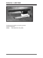
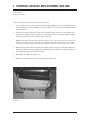
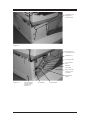
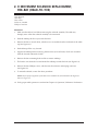
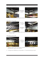
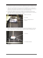
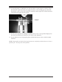
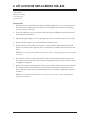
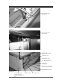
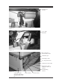
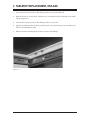
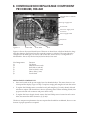
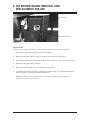
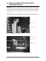
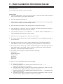
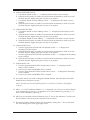
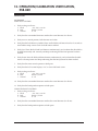
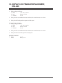
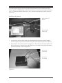
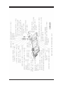
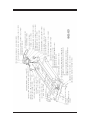
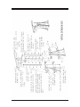
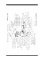
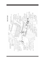
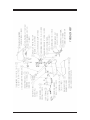
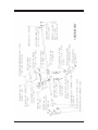
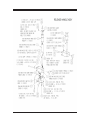
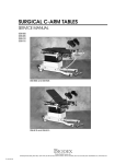
SURGICAL C-ARM TABLE
SERVICE MANUAL
058-840
058-845
058-840
BIODEX
Biodex Medical Systems, Inc.
20 Ramsay Road, Shirley, New York, 11967-4704, Tel: 800-224-6339 (Int’l 631-924-9000), Fax: 631-924-9241, Email: [email protected], www.biodex.com
FN: 10-218 11/10
SURGICAL C-ARM TABLE
058-840
This manual covers installation and operation procedures
for the following product:
#058-840
#058-845
Table, Surgical C-Arm - 840, 115 VAC
Table, Surgical C-Arm - 840, 230 VAC
— II —
TABLE OF CONTENTS
1. CONTROL MODULE REPLACEMENT, 058-840
2. X MOVEMENT SOLENOID REPLACEMENT, 058- 840 (HEAD-TO-TOE)
3. Y MOVEMENT SOLENOID REPLACEMENT, 058-840 (LATERAL)
4. LIFT ACTUATOR REPLACEMENT, 058-840
5. LATERAL TILT ACTUATOR REPLACEMENT, 058-840
6. HEAD-TO-TOE TILT ACTUATOR REPLACEMENT, 058-840
7. TABLETOP REPLACEMENT, 058-840
8. CONTROLLER BOX REPLACEABLE COMPONENT PROCEDURE, 058-840
9. TILT SENSOR BOARD REMOVAL AND REPLACEMENT, 058-840
10. POSITION SENSING STRIP REPLACEMENT PROCEDURE, 058-840
11. TABLE CALIBRATION PROCEDURE, 058-840
12. OPERATION/CALIBRATION VERIFICATION, 058-840
13. DISPLAY LCD PENDANT REPLACEMENT, 058-840
14. TABLE FIRMWARE UPDATE, 058-840
15. PART AND ASSEMBLY ILLUSTRATIONS, 058-840
— III —
CONTENTS
1. CONTROL MODULE REPLACEMENT, 058-840
Tools Required:
Phillips screwdriver
The control module is located on the lower back panel.
1.
To access the control module, remove the four larger Phillips screws securing the lower portion of the bellows to the clamshell covers. Each side has two screws located near the center
of the clamshell.
2.
The bellows is still secured to the top of the clamshell covers, but now it can be lifted and
secured with bungee cords (see Figure 1.1). The table must be raised to its highest position
to allow clearance to access and remove the controller.
NOTE: If the table cannot be raised to the up position the covers must be removed. First remove the
remaining 12 Phillips screws securing the lower portion of the bellows to the covers. Next, separate
the covers by removing the four securing screws located at each end, and then slide the covers out.
3.
Remove the six screws that secure the lower back panel (see Figure 1.2). Remove the lower
back panel. Slide the control module out carefully. Make sure that the connecting cables are
not being damaged as you slide the box out.
4.
Disconnect all cables (see Figure 1.3).
5.
Remove the six nuts that secure the module to the back panel.
Figure 1.1.
—1—
CONTROL MODULE REPLACEMENT
CONTENTS
Six Phillips screws
securing side
cover/control box
Figure 1.2.
The Control box is
secured with six nuts
Calibration port
LCD display cable
X, Y, tilt position
sense
Hand/Foot
control cable
Main power coiled
cable for X and Y,
roll actuator
Trendelenburg
actuator
Figure 1.3.
LCD display cable
connector used for
reprogramming
control box
CONTROL MODULE REPLACEMENT
AC pwr/battery
—2—
Vertical actuator
2. X MOVEMENT SOLENOID REPLACEMENT,
058-840 (HEAD-TO-TOE)
Tools Required:
Allen keys
Wire cutters
Socket set, standard
Phillips screwdriver
REMOVAL
1. Make sure the table is level before removing the solenoid assembly. The table may
abruptly move when the solenoid assembly is disconnected.
2.
Slide the tabletop all the way towards the back.
3.
Remove the four 9/16-inch bolts, which are now accessible from the underside of the tabletop (see Figure 2.1).
4.
Slide tabletop all the way forward.
5.
Support the tabletop before removing the final four 9/16-inch bolts, which are accessible
from the forward underside of table.
6.
Remove the four remaining bolts and lift to remove tabletop.
7.
The head to toe solenoid is located under the tabletop towards the back (see Figure 2.2).
8.
Remove the four Phillips screws, which secure the solenoid, and unplug connector
(see Figure 2.2).
9.
To reinstall solenoid, reverse the above procedure.
NOTE: Insure proper alignment of solenoid arm to mechlock tab, which should be 90 degrees as
shown in Figure 2.2.
10. Verify proper table operation as outlined in Chapter 12, Operation/Calibration Verification.
—3—
X MOVEMENT SOLENOID REPLACEMENT
CONTENTS
Figure 2.1.
Figure 2.2.
X MOVEMENT SOLENOID REPLACEMENT
—4—
3. Y MOVEMENT SOLENOID REPLACEMENT,
058-840 (LATERAL)
X-MECHLOCK (058-840-A040) AND Y-MECHLOCK (058-840-A030) REPLACEMENT AND
CLEANING
Model 058-840 Series Tables
Tools Required:
Medium Phillips screwdriver
9/16-inch Wrench
3/8-inch Wrench
1/2-inch Wrench
7/16-inch Wrench
5/32-inch Allen Key
3/16-inch Allen Key
Wire Cutter
C13349 Lubrication for Piston
1.
Level and raise the tabletop to position 10 (the highest point).
Foot End of Table
Head End of Table
2.
Remove the eight 9/16-inch Tabletop bolts with a 9/16-inch wrench. Two of the bolts do
not have washers. This is to prevent the nylon wheel measuring device from getting hit by
the bolts. Place some sort of weight on the foot end of the table to support it from falling.
a.
Move the tabletop all the way to position zero on the forward and back
(head end of the table) to access the four bolts.
—5—
Y MOVEMENT SOLENOID REPLACEMENT
CONTENTS
Underneath Head End of Table
Remove four
9/16-inch bolts
w/Washers
b.
Move the tabletop all the way to position 20 (foot end of the table) to access the four bolts.
Underneath Foot End of Table
Remove two
9/16-inch bolts
w/o washers
Remove two
9/16-inch bolts
w/washers
c.
Remove the four 3/8-inch tabletop extension nuts at the foot end of the table with a
3/8-inch wrench.
Underneath Foot End of Table
Remove four
3/8-inch nuts
w/washers
3.
Unplug the table from the wall and make sure that the switch is in the OFF position.
There should be no power to the control box.
4.
To change out the Y-Mechlock go to step number 10. To clean the solenoid go to step 15.
Y MOVEMENT SOLENOID REPLACEMENT
—6—
CONTENTS
5.
To change out the X-Mechlock unplug the wire harness connector.
6.
Remove the 5/32-inch bolts and washers with a 5/32-inch Allen Key. They are located on
the outside of the foot end of the table by the handle.
Remove two
5/32-inch
Allen Head Bolts
w/washers
7.
Remove the 7/16-inch bolts and washers from the inside of the table. They are next to the
Mechlock itself.
Remove two
7/16-inch bolts
w/washers
—7—
Y MOVEMENT SOLENOID REPLACEMENT
CONTENTS
8.
You should now be able to remove the broken X-Mechlock and replace it with the new one.
9.
After you have put the bolts back into place reconnect the Mechlock. Turn on the power
and test for correct operation. (You shouldn’t have to recalibrate the table for the X direction
because the pot that measures the location was not removed from the table.)
10. To remove the Y-Mechlock, remove the two Phillip screws that hold the bracket for the
nylon wheel and remove it from the table. Cut the zip tie that holds the power connector in
place with a wire cutter and disconnect the connector.
Bracket for Nylon Wheel
Nylon Wheel
Remove two Phillip Head Screws
Cut Zip Tie
11. Remove the 3/16-inch Allen Head Pivot Bolt with a Allen Key by holding the 1/2-inch nut
with a 1/2-inch wrench. You should be able to slide the clevis block off of the pivot bolt.
-inch
1/2-inch nut
3/16-inch Allen Head Bolt
clevis block
Y MOVEMENT SOLENOID REPLACEMENT
—8—
CONTENTS
12. Remove the 3/16-inch Allen Head Bolt that holds the solenoid to the bracket.
Remove
3/16-inch Allen Head Bolt
13. Loosen the 3/16-inch hex nut on the other side. You will have to use a short length Allen
key to reach the nut.
Loosen
3/16-inch Allen Head Bolt
14. You should now be able to remove the bad Mechlock. Place the new Mechlock into the table.
—9—
Y MOVEMENT SOLENOID REPLACEMENT
CONTENTS
15. To clean the piston on a Mechlock you must use either a contact cleaner or alcohol. Shoot
the solenoid a couple times after you apply the cleaner. This will help get any dirt inside
the solenoid. After you have the solenoid completely cleaned apply the C13349 Lubrication
to the piston and again shoot the piston.
Piston on
Solenoid
16. Test for correct operation by sliding the tabletop side to side. If your pendant display does
not read L5 to R5 then you will have to do a side to side calibration.
17. If your table does not work properly please call 800-224-6339 ext. 2124 or 2125 for further
assistance.
NOTE: Always make sure that all of the plugs/connectors are completely in and that there are no bent or
pushed in pins. This may cause erratic operation.
Y MOVEMENT SOLENOID REPLACEMENT
— 10 —
4. LIFT ACTUATOR REPLACEMENT, 058-840
Tools Required
Phillips screwdriver
5 mm Allen key
8 mm wrench
PROCEDURE
1. If the lift actuator is operational, the table should be brought down to its lowest position. If
the actuator is not operational, the tabletop must be supported to prevent it from falling
once the actuator is removed.
2.
Lower the tabletop to its lowest position and remove the 18 Phillips screws that secure the
lower portion of the bellows.
3.
Remove the eight Phillips screws securing the top covers, and remove one cover at a time.
4.
Remove the lower right cover secured with nine Phillips screws.
5.
Remove the lower back panel (see Chapter 1, Control Module Replacement). Only three
panels now remain on the right side since you should have already removed the lower left
panel.
NOTE: Be sure to support the tabletop on both ends to prevent it from dropping once the lift actuator
is removed.
6.
The actuator is secured at both ends with a 5 mm Allen head shoulder bolt and an 8 mm
nut. (Figure 6.1 shows the lift actuator bottom-securing bolt. Figure 6.2 shows the lift actuator upper securing bolt.)
7.
Remove the actuator and unplug the actuator power cable at the RCA jack on the controller
box. (Figure 6.3 shows the control box and vertical lift actuator RCA plug location. Also,
refer to the parts section drawing labeled I-Base Assy. for assembly components and part
numbers.)
NOTE: For reinstallation of the actuator, reverse the process and test for proper operation before
installing the enclosures.
— 11 —
LIFT ACTUATOR REPLACEMENT
CONTENTS
Lift actuator lower
bolt and nut
Figure 4.1
Lift actuator upper
bolt and nut
Figure 4.2.
Control box is
secured with six nuts
Calibration port
LCD display cable
X, Y, tilt position sense
Hand/Foot
control cable
Main power coiled cable
for X and Y, roll actuator
Trendelenburg actuator
Figure 4.3.
LCD display cable
AC pwr/battery
connector used for
reprogramming control
box
LIFT ACTUATOR REPLACEMENT
— 12 —
Vertical actuator
5. LATERAL TILT ACTUATOR REPLACEMENT,
058-840
PROCEDURE
1. If the lateral tilt actuator is operational, tilt it down on the patient right side. The table
should be brought head down to its lowest position. If the actuator is not operational, the
tabletop must be supported to prevent the tabletop from suddenly tilting once the actuator
is removed.
2.
The actuator is located inside the bellow on the patient right side. Remove the 18 Phillips
screws that secure the lower portion of the bellows.
3.
Remove the eight Phillips screws that secure the top covers, and then remove the covers one
at a time.
4.
Remove the lower right cover that is secured with nine Phillips screws.
5.
Remove the lower back panel. (Six screws secure the lower back panel, but only three
remain on the right side since you should have already removed the lower left panel.)
NOTE: Be sure to support the tabletop to prevent it from dropping once the lateral tilt actuator is
removed.
6.
The actuator is secured to the table with a 3/16-inch Allen head shoulder bolt and 1/2-inch
nut. (Figure 7.1 shows the securing bolt assembly). In addition, the acme nut is secured with
two 3/16-inch bolts. (Figure 7.2 shows the acme nut assembly.)
7.
Remove the actuator and unplug the actuator power cable at connector #3 on the controller
box. (Figure 7.3 shows the control box and actuator plug location #3. Also refer to the parts
section drawing, labeled Base Top Assembly for assembly components and part numbers.)
NOTE: For reinstallation of the actuator, reverse the process and test for proper operation before
installing the enclosures.
— 13 —
LATERAL TILT ACTUATOR REPLACEMENT
CONTENTS
Securing bolt
and nut.
Figure 5.1
3/16" Allen
head bolts
Figure 5.2.
The control box is
secured with six nuts
Calibration port
LCD display cable
X, Y, tilt position sense
Hand/Foot control cable
Main power coiled
cable for X and Y, roll
actuator
Trendelenburg
actuator
Figure 5.3.
LCD display cable
Connector and used for
reprogramming control
box
LATERAL TILT ACTUATOR REPLACEMENT
AC pwr/battery
— 14 —
Vertical actuator
6. HEAD-TO-TOE TILT ACTUATOR REPLACEMENT,
058-840
PROCEDURE
1. If the tilt actuator is operational, the table should be brought head down to its lowest position. If the actuator is not operational, the tabletop must be supported to prevent the top
from suddenly tilting once the actuator is removed.
2.
Tilt the top head down to its lowest position, and remove the eighteen Phillips screws that
secure the lower portion of the bellows.
3.
Remove the eight Phillips screws securing the top covers, and then remove the covers one at
a time.
4.
Remove the lower right cover secured with nine Phillips screws.
5.
Remove the lower back panel. (Six screws secure the lower back cover, but only three
remain on the right side since you should have already removed the lower left panel.)
NOTE: Support the tabletop to prevent it from dropping once the tilt actuator is removed.
6.
The actuator is secured at both ends with a pin and C-clip. Remove the clip and pull the
pins out. (Figure 8.1 shows the lift actuator bottom-securing bolt. Figure 8.2 shows the lift
actuator upper securing bolt. Refer to the illustrated parts section with the page entitled
I – Base Assy , see item #51.)
7.
Remove the actuator and unplug the actuator power cable at the RCA connector on the controller box. Figure 8.3 shows the control box and actuator plug location.
NOTE: To reinstall the actuator, reverse the process and test for proper operation before installing the
enclosures.
— 15 —
HEAD-TO-TOE TILT ACTUATOR REPLACEMENT
CONTENTS
Actuator lower
securing pin and clip
Figure 6.1.
Actuator upper
securing pin and clip
Figure 6.2.
Trendelenburg
actuator
Figure 6.3.
HEAD-TO-TOE TILT ACTUATOR REPLACEMENT
— 16 —
7. TABLETOP REPLACEMENT, 058-840
1.
Activate the X motor and move the tabletop all the way towards the back.
2.
Remove the four 9/16-inch bolts, which are now accessible from the underside of the tabletop (see Figure 9.1).
3.
Activate the X motor and move the tabletop all the way forward.
4.
Support the tabletop before removing the final four 9/16-inch bolts that are accessible from
the forward underside of table.
5.
Remove the four remaining bolts and lift to remove the tabletop.
Figure 7.1.
— 17 —
TABLETOP REPLACEMENT
8. CONTROLLER BOX REPLACEABLE COMPONENT
PROCEDURE, 058-840
H-bridge motor controller
boards
5v logic supply fuse
Fowler back
24v Power supply fuses
for motors
Power supply board
UP/Down
Pitch
Figure 8.1.
Side to Side
Front/Back
Roll
Figure 8.1 shows the control board layout. There are six board slots, which are labeled to designate their function. Each board activates a specific actuator or solenoid. The control board is
configured to the table type it is used in. The control box, shown above, is configured for a
058-830 table - that is why the last slot J8 (Fowler Back) is not used.
Slot Designations
J3
J4
J5
J6
J7
J8
Function
Up/Down
Pitch (head to toe tilt)
Roll (side to side tilt)
Front to Back (x axis)
Side to Side (y axis)
Fowler back
REPLACEABLE COMPONENTS
• Fuses are located on the power supply board as identified above. The motor fuses two are
15-amp and the display/logic is 2-amp. To replace, simply pull straight out from the socket.
•
To replace the H-bridge motor controller board, pull straight up. To easily identify if board
is defective replace with board from a known operating motor. When installing boards, line
up pins on board with connector and press down evenly.
•
To replace the Power Supply board, remove the four Phillips screws located at each corner.
Next, disconnect the three connectors, J3, J5 & J6.
The above component replacement does not require that the table be recalibrated; however verification of proper operation is required.
— 19 —
CONTROLLER BOX REPLACEABLE COMPONENT
9. TILT SENSOR BOARD REMOVAL AND
REPLACEMENT, 058-840
Connector
Tilt Sensor Board
Figure 9.1.
PROCEDURE
The tilt sensor is under the tabletop, on the patient left side next to lateral tilt actuator.
1.
Raise table to maximum height, for better accessibility.
2.
Remove the eighteen Phillips screw securing the lower portion of the bellow.
3.
Lift the bellows and secure in the up position. This provides you with access to the sensor.
4.
Disconnect the signal cable connector.
5.
Remove the three Phillips screws securing the sensor board.
6.
To reinstall the Tilt Sensor board, reverse the procedure above. For a detailed illustration
refer to Chapter 15, Part and Assembly illustrations.
NOTE: The table must be recalibrated when a new sensor is installed. Refer to Chapter 11,
Calibration Procedure for instructions.
— 21 —
TILT SENSOR BOARD REMOVAL
10. POSITION SENSING STRIP REPLACEMENT,
PROCEDURE 058-840
PROCEDURE
The table utilizes three precision resistor strips to sense the table’s height and X, Y tabletop position. Figure 10.1 shows the resistor strip installed on the table. The wiper/roller move along the
resistor strip as the position of the table changes. The resistance change is in direct correlation to
the wiper position. Any changes in resistance are converted to position counts, which are shown
on the display.
NOTE: Refer to Chapter 4, Lift Actuator Replacement, steps one through four, to access the position strip for
replacement. Refer to Chapter 7, Tabletop Replacement, to access X and Y position strip for replacement.
Resistor wiper
Resistor strip
Figure 10.1. Height position sensing resistor strip
Resistor connector
Resistor strip
Resistor wiper
Figure 10.2. Y position sensing resistor strip (solenoid assembly, tabletop removed)
— 23 —
POSITION SENSING STRIP REPLACEMENT
CONTENTS
Resistor strip wiper
Y position
resister strip
Y-motor
Wiper bracket
securing screws
Figure 10.3. Y position sensing resistor strip (actuator assembly, tabletop removed)
Resistor strip
Resistor wipes
Figure 10.4. X position sensing resistor strip (tabletop removed for viewing)
Figure 10.5. Resistor strip not installed. Note that the strip is secured with adhesive to a thin metal mounting
plate. The mounting plate is attached to the designated location with two Phillips screws at each end.
POSITION SENSING STRIP REPLACEMENT
— 24 —
CONTENTS
REPLACING THE RESISTOR STRIP
To replace the resistor strip, remove the two securing screws. Next, lift wiper/roller and remove
the strip (strip may also be secured with adhesive). When any sensor is replaced a table calibration is required. Refer to Chapter 11, Calibration Procedure, for instructions.
— 25 —
POSITION SENSING STRIP REPLACEMENT
11. TABLE CALIBRATION PROCEDURE, 058-840
Required Equipment
PC with latest table calibration software installed
PROCEDURE
1. Connect COMM PORT 1 of the PC to the 9 pin male "D" connector of the table’s control box,
using a 9 pin female to 9 pin female RS-232 cable.
2.
Turn the computer and monitor on.
3.
When Windows is finished booting, double-click the left mouse button on the Image Table
icon on the PC's desktop, to start the utility software.
4.
Enter the table serial number in the appropriate box in the utility software.
5.
Turn the table ON. "Welcome", "Press C to Calibrate" and other information or characters
may be displayed in the software's receive window.
6.
Click the left mouse button on "CALIBRATE." "++++ IMAGE TABLE CALIBRATION ++++"
will be displayed in the software's receive window.
7.
Follow the on-screen prompts in the utility's receive window.
8.
The current selection for the type of table is displayed. This can be changed by pressing "Y"
on the keyboard.
9.
The table type choices are: 1) 870/C-ARM, 2) 840 Float Top, 3) Lithotripsy, 4) 800/810
URO/BRACH. Select the correct table type by pressing number 1-4 on the keyboard.
10. The current selection for the type of motor installed is displayed. The motor type choice is
either High Speed or Low Speed. If this is incorrect, the motor type can be changed by
pressing "Y" on the keyboard, otherwise press "N".
11. You will be given the option to calibrate each of the following:
UP/DOWN
FORWARD/BACK
SIDE TO SIDE
JOYSTICK
PITCH Axis
ROLL Axis
12. Select "Y" for each and follow the on-screen prompts.
13. To Calibrate UP/DOWN:
a. Press the appropriate UP or DOWN hand switch button so that "+ +" is
displayed in the utility's receive window.
b. When the MAX Position is reached, reverse direction momentarily to back away from
the MAX Position slightly, then press any key to set position.
c. Press the appropriate UP or DOWN hand switch button so that "- -" is displayed in the
utility's receive window.
d. When the MAX Position is reached, reverse direction momentarily to back away from
the MAX Position slightly, then press any key to set position.
— 27 —
TABLE CALIBRATION PROCEDURE
CONTENTS
14. Calibrate FORWARD/BACK:
a. Use Release Handle so that "+ +" is displayed in the utility's receive window.
b. When the MAX Position is reached, reverse direction momentarily to back away from
the MAX Position slightly, then press any key to set position.
c. Use Release Handle to move tabletop so that "- -" is displayed in the utility's receive
window.
d. When the MAX Position is reached, reverse direction momentarily to back away from
the MAX Position slightly, then press any key to set position.
15. Calibrate SIDE TO SIDE:
a. Use Release Handle to move tabletop so that "+ +" is displayed in the utility's receive
window.
b. When the MAX Position is reached, reverse direction momentarily to back away from
the MAX Position slightly, then press any key to set position.
c. Use Release Handle to move tabletop "- -" is displayed in the utility's receive window.
d. When the MAX Position is reached, reverse direction momentarily to back away from
the MAX Position slightly, then press any key to set position.
16. Calibrate PITCH Axis:
a. Press the appropriate PITCH hand switch button so that "+ +" is displayed in
the utility's receive window.
b. When the MAX Position is reached, reverse direction momentarily to back away from
the MAX Position slightly, then press any key to set position.
c. Press the appropriate PITCH hand switch button so that "- -" is displayed in the utility's
receive window.
d. When the MAX Position is reached, reverse direction momentarily to back away from
the MAX Position slightly, then press any key to set position.
17. Calibrate ROLL Axis:
a. Press the appropriate ROLL hand switch button so that "+ +" is displayed in the
utility's receive window.
b. Press any key when 18 DEGREES TILT is reached.
c. Press the appropriate ROLL hand switch button so that "- -" is displayed in the utility's
receive window.
d. Press any key when 18 DEGREES TILT is reached.
18. You will be asked if you need to change the HOME Position. Move the table to the NEW
HOME Position, then press any key.
NOTE: The table must have the HOME position set to Full Down, Full Back, and Left/Right
Centered.
19. When "****** EXIT Calibration MODE ******" is displayed you can choose to discard the previous calibration by pressing "C" to recalibrate, or save the calibration by pressing "S," or
load a saved calibration by pressing "L".
20. When you are satisfied with the calibration, press "S" to save the calibration. Various numbers and letters will scroll by in the software's receive window.
21. The Imaging Table Calibration Utility may be exited by clicking File --> Exit on the menu
bar or by clicking the X in the upper right corner.
TABLE CALIBRATION PROCEDURE
— 28 —
12. OPERATION/CALIBRATION VERIFICATION,
058-840
PROCEDURE
AC Powered
MAIN LCD CONTROL
1.
Verify scaling on all axes.
a. Pitch
-1 to –20, 0, 1 to 20
b. Roll
R1-20, 0, L1-20
c. Vertical
0 - 10
2.
Verify that the commanded direction matches the actual direction for all axes.
3.
Verify move to stored position, both direction and value.
4.
Verify that the hold button is enabled. Press and hold the soft button four for 15 seconds to
enter hidden setup screen. Check for hold button enabled.
5.
Verify level. Press the hold and level buttons simultaneously, and confirm that the table levels both horizontally and vertically and beeps indicating that the final position has been
reached.
6.
Verify home. Press the hold and home buttons simultaneously, and confirm that the table
moves to home position and beeps indicating that the final position has been reached.
7.
Verify that the main control operates in both ports.
8.
Verify that the LCD screen Displays "AC" in lower left hand corner.
9.
Verify scaling on all axes.
a. Pitch
-1 to –20, 0, 1 to 20
b. Roll
R1-20, 0, L1-20
c. Vertical
0 - 10
10. Verify that the commanded direction matches the actual direction for all axes.
11. Verify that the hand pendent operates in both ports.
HAND PENDANT CONTROL
1. Verify scaling on all axes.
a. Pitch
-1 to –20, 0, 1 to 20
b. Roll
R1-20, 0, L1-20
c. Vertical
0 - 10
2.
Verify that the commanded direction matches the actual direction for all axes.
3.
Verify that the hand pendent operates in both ports.
— 29 —
OPERATION/CALIBRATION VERIFICATION
CONTENTS
FOOTSWITCH CONTROL
1. Verify scaling on all axes.
a. Pitch
-1 to –20, 0, 1 to 20
b. Roll
R1-20, 0, L1-20
c. Vertical
0 - 10
2.
Verify that the commanded direction matches the actual direction for all axes.
3.
Verify that the footswitch operates in both ports.
BATTERY Powered
MAIN LCD CONTROL
1. Verify scaling on all axes.
a. Pitch
-1 to –20, 0, 1 to 20
b. Roll
R1-20, 0, L1-20
c. Vertical
0 - 10
2.
Verify that the commanded direction the matches actual direction for all axes.
3.
Verify move to stored position, both direction and value.
4.
Verify that the hold button is enable. Press and hold the soft button four for 15 seconds to
enter hidden setup screen. Check for hold button enabled.
5.
Verify level. Press the hold and level buttons simultaneously, and confirm that the table levels both horizontally and vertically and beeps indicating that the final position has been
reached.
6.
Verify home. Press the hold and home buttons simultaneously, and confirm that the table
moves to home position and beeps indicating that the final position has been reached.
7.
Verify that the main control operates in both ports.
8.
Verify that the LCD screen Displays "BATT" in lower left hand corner.
OPERATION/CALIBRATION VERIFICATION
— 30 —
13. DISPLAY LCD PENDANT REPLACEMENT,
058-840
HAND PENDANT CONTROL
1. Verify scaling on all axes.
a. Pitch
-1 to –20, 0, 1 to 20
b. Roll
R1-20, 0, L1-20
c. Vertical
0 - 10
2.
Verify that the commanded direction matches the actual direction for all axes.
3.
Verify that the hand pendent operates in both ports.
FOOTSWITCH CONTROL
1. Verify scaling on all axes.
a. Pitch
-1 to –20, 0, 1 to 20
b. Roll
R1-20, 0, L1-20
c. Vertical
0 - 10
2.
Verify that the commanded direction matches the actual direction for all axes.
3.
Verify that the footswitch operates in both ports.
RELEASE HANDLE
4. X-axis
Y-axis
0 – 20
R1-5, 0, L1-5
— 31 —
DISPLAY PENDANT REPLACEMENT
CONTENTS
The LCD Pendant displays and stores position information and controls all the motor movements, up/down, Trendelenburg /rev, lateral roll, head to toe actuator (X) and side-to-side actuator (Y). The Release Handle releases the X and Y solenoids simultaneously, which allows the
top to float.
REMOVAL OF DISPLAY
Release/Removal
buttons
Release handle
for float top
Figure 13.1.
1.
To remove the display, lift the display up while depressing the release/removal buttons.
Also the Display can positioned anywhere along the rail by depressing the release buttons.
2.
Disconnect the two connectors shown in Figure 15.1. The connectors are color-coded for the
blue is main power/communication cable and white is for either the release handle (840) or
joystick (830), based on table configuration.
White connector
for power cable
Blue connector
for power cable
Figure 13.2.
DISPLAY PENDANT REPLACEMENT
— 32 —
14. TABLE FIRMWARE UPDATE, 058-840
1.
Connect the PC to the 9 pin female "D" connector of the control box, using the special 9 pin
female to 9 pin male DSP programming cable.
2.
Turn the computer and monitor on.
3.
Turn the table on.
4.
When Windows is finished booting, double-click the left mouse button on the Image table
icon on the PC's desktop to start the utility software.
5.
Enter the table serial number in the appropriate box in the utility software.
6.
Click on the PROGRAM LCB to begin the firmware update.
7.
When the update is complete, close any newly opened windows by clicking the X in the
upper right corner of each window.
8.
The Imaging Table Calibration Utility may be exited by clicking File --> Exit on the menu
bar or by clicking the X in the upper right corner.
— 33 —
TABLE FIRMWARE UPDATE
15. PART AND ASSEMBLY ILLUSTRATIONS,
058-840
— 35 —
058-840 PART AND ASSEMBLY ILLUSTRATIONS
058-840 PART AND ASSEMBLY ILLUSTRATIONS
— 36 —
— 37 —
058-840 PART AND ASSEMBLY ILLUSTRATIONS
058-840 PART AND ASSEMBLY ILLUSTRATIONS
— 38 —
— 39 —
058-840 PART AND ASSEMBLY ILLUSTRATIONS
058-840 PART AND ASSEMBLY ILLUSTRATIONS
— 40 —
— 41 —
058-840 PART AND ASSEMBLY ILLUSTRATIONS
058-840 PART AND ASSEMBLY ILLUSTRATIONS
— 42 —
— 43 —
058-840 PART AND ASSEMBLY ILLUSTRATIONS
058-840 PART AND ASSEMBLY ILLUSTRATIONS
— 44 —
— 45 —
058-840 PART AND ASSEMBLY ILLUSTRATIONS
058-840 PART AND ASSEMBLY ILLUSTRATIONS
— 46 —
— 47 —
058-840 PART AND ASSEMBLY ILLUSTRATIONS
058-840 PART AND ASSEMBLY ILLUSTRATIONS
— 48 —
— 49 —
058-840 PART AND ASSEMBLY ILLUSTRATIONS
058-840 PART AND ASSEMBLY ILLUSTRATIONS
— 50 —
— 51 —
058-840 PART AND ASSEMBLY ILLUSTRATIONS
058-840 PART AND ASSEMBLY ILLUSTRATIONS
— 52 —
— 53 —
058-840 PART AND ASSEMBLY ILLUSTRATIONS
058-840 PART AND ASSEMBLY ILLUSTRATIONS
— 54 —
NOTES
— 55 —
NOTES
Certified Quality Management System
BIODEX
Biodex Medical Systems, Inc.
20 Ramsay Road, Shirley, New York, 11967-4704, Tel: 800-224-6339 (Int’l 631-924-9000), Fax: 631-924-9241, Email: [email protected], www.biodex.com