1
Model 3200
PROGRAMMER USER’S MANUAL
EMBLEM™ S-ICD Programmer
CAUTION: Federal law (USA) restricts this device
to sale by or on the order of a physician trained
or experienced in device implant and follow-up
procedures.
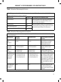
LIST OF ACRONYMS
AC
Alternating current
IC
Industry Canada
ATP
Anti-tachycardia pacing
LCD
Liquid crystal display
CRT
Cardiac resynchronization therapy
MRI
Magnetic resonance imaging
CPR
Cardiopulmonary resuscitation
NSR
Normal sinus rhythm
ECG
Electrocardiogram
S-ECG
Subcutaneous electrocardiogram
EMI
Elecromagnetic interference
S-ICD
Subcutaneous implantable
cardioverter defibrillator
EOL
End of life
USB
Universal serial bus
ERI
Elective replacement indicator
VAC
Voltage alternating current
ESD
Electrostatic discharge
VF
Ventricular fibrillation
FCC
Federal Communications
Commission
VT
Ventricular tachycardia
GUI
Graphic user interface
This literature is intended for use by professionals trained or experienced in device implant and/or
follow-up procedures.
EMBLEM is a trademark of Boston Scientific Corporation.
This product may be protected by one or more patents.
Patent information can be obtained at http://www.bostonscientific.com/patents.
The Bluetooth® word mark and logos are registered trademarks owned by Bluetooth SIG, Inc., and any use of
such marks is under license.
microSD is a trademark or registered trademark of SD-3C, LLC.
© Copyright 2015 Boston Scientific or its affiliates.
All rights reserved.
TABLE OF CONTENTS
GENERAL DESCRIPTION
Description��������������������������������������������������������������������������������������������������������������������������������1
Intended Use of Programmer��������������������������������������������������������������������������������������������������1
Indications for Use��������������������������������������������������������������������������������������������������������������������1
Contraindications���������������������������������������������������������������������������������������������������������������������1
Related Information�����������������������������������������������������������������������������������������������������������������2
Programmer Warnings and Precautions���������������������������������������������������������������������������������2
Programmer Warnings��������������������������������������������������������������������������������������������������������������������������������������2
General�������������������������������������������������������������������������������������������������������������������������������������������������������������2
Conditions for Operation���������������������������������������������������������������������������������������������������������������������������3
Programmer Precautions����������������������������������������������������������������������������������������������������������������������������������4
General�������������������������������������������������������������������������������������������������������������������������������������������������������������4
Storage and Handling���������������������������������������������������������������������������������������������������������������������������������4
Implantation���������������������������������������������������������������������������������������������������������������������������������������������������4
Conditions for operation����������������������������������������������������������������������������������������������������������������������������4
S-ICD System Warnings and Precautions��������������������������������������������������������������������������������5
S-ICD System Warnings�������������������������������������������������������������������������������������������������������������������������������������5
General�������������������������������������������������������������������������������������������������������������������������������������������������������������5
Post-Implant���������������������������������������������������������������������������������������������������������������������������������������������������5
Clinical Considerations�������������������������������������������������������������������������������������������������������������������������������6
Implantation���������������������������������������������������������������������������������������������������������������������������������������������������6
Device Programming����������������������������������������������������������������������������������������������������������������������������������7
S-ICD System Precautions��������������������������������������������������������������������������������������������������������������������������������7
Environmental and Medical Therapy Hazards������������������������������������������������������������������������������������7
Hospital and Medical Environments������������������������������������������������������������������������������������������������������7
Follow-up Testing�������������������������������������������������������������������������������������������������������������������������������������� 12
Explant and Disposal�������������������������������������������������������������������������������������������������������������������������������� 12
Supplemental Precautionary Information���������������������������������������������������������������������������������������� 13
S-ICD System Clinical Investigation����������������������������������������������������������������������������������������������������������� 13
Potential Adverse Events������������������������������������������������������������������������������������������������������������������������������� 13
OPERATION
Programmer Setup���������������������������������������������������������������������������������������������������������������� 16
Packaging������������������������������������������������������������������������������������������������������������������������������������������������������������ 16
Programmer Controls and Connections�������������������������������������������������������������������������������������������������� 16
Charging the Programmer���������������������������������������������������������������������������������������������������������������������������� 17
Using the Programmer���������������������������������������������������������������������������������������������������������� 19
Turning the Programmer On������������������������������������������������������������������������������������������������������������������������ 19
Changing the Programmer Volume Level����������������������������������������������������������������������������������������������� 19
Placing the Programmer in Suspend Mode�������������������������������������������������������������������������������������������� 20
Turning the Programmer Off����������������������������������������������������������������������������������������������������������������������� 20
Using the Programmer Touch Screen������������������������������������������������������������������������������������������������������� 20
Using the Wand������������������������������������������������������������������������������������������������������������������������������������������������� 21
Navigation���������������������������������������������������������������������������������������������������������������������������������������������������������� 23
Screen Header��������������������������������������������������������������������������������������������������������������������������������������������������� 23
Navigation Bar��������������������������������������������������������������������������������������������������������������������������������������������������� 23
Restarting the Programmer�������������������������������������������������������������������������������������������������������������������������� 24
Configuring the Programmer������������������������������������������������������������������������������������������������ 26
Configuring Programmer Settings������������������������������������������������������������������������������������������������������������� 26
Date and Time Format������������������������������������������������������������������������������������������������������������������������������������ 27
Time Zone����������������������������������������������������������������������������������������������������������������������������������������������������������� 28
Language Preference�������������������������������������������������������������������������������������������������������������������������������������� 29
Printer Selection����������������������������������������������������������������������������������������������������������������������������������������������� 30
Bluetooth® Data Export���������������������������������������������������������������������������������������������������������������������������������� 32
Programmer Software Version�������������������������������������������������������������������������������������������������������������������� 34
Programmer Modes of Operation���������������������������������������������������������������������������������������� 35
Online Behavior������������������������������������������������������������������������������������������������������������������������������������������������ 35
Offline Behavior������������������������������������������������������������������������������������������������������������������������������������������������ 35
Stored Patient Sessions���������������������������������������������������������������������������������������������������������������������������������� 35
To view stored patient sessions������������������������������������������������������������������������������������������������������������������ 36
Modes of Operation for the Pulse Generator���������������������������������������������������������������������� 36
Shelf Mode ��������������������������������������������������������������������������������������������������������������������������������������������������������� 36
Therapy On Mode�������������������������������������������������������������������������������������������������������������������������������������������� 36
Therapy Off Mode�������������������������������������������������������������������������������������������������������������������������������������������� 36
Connecting and Disconnecting from the S-ICD Pulse Generator�������������������������������������� 37
Scanning for Pulse Generators�������������������������������������������������������������������������������������������������������������������� 37
Connecting to a Pulse Generator��������������������������������������������������������������������������������������������������������������� 38
Connecting to a Pulse Generator in Shelf Mode ���������������������������������������������������������������������������������� 38
Connecting to an Implanted Pulse Generator �������������������������������������������������������������������������������������� 39
Ending a Patient Session������������������������������������������������������������������������������������������������������������������������������� 40
Programming the Pulse Generator at Implant�������������������������������������������������������������������� 42
Entering Electrode Information������������������������������������������������������������������������������������������������������������������ 42
Creating the Patient Chart���������������������������������������������������������������������������������������������������������������������������� 45
Automatic Setup����������������������������������������������������������������������������������������������������������������������������������������������� 46
Programming Therapy Parameters������������������������������������������������������������������������������������������������������������ 50
Defibrillation Testing��������������������������������������������������������������������������������������������������������������������������������������� 53
Performing a Follow-up��������������������������������������������������������������������������������������������������������� 58
Sensing Configuration and Automatic Setup���������������������������������������������������������������������������������������� 58
Viewing Pulse Generator Status������������������������������������������������������������������������������������������������������������������ 58
Viewing Stored Episodes������������������������������������������������������������������������������������������������������������������������������� 59
Printing Reports from the Programmer������������������������������������������������������������������������������� 61
Printing Reports������������������������������������������������������������������������������������������������������������������������������������������������ 61
Summary Report���������������������������������������������������������������������������������������������������������������������������������������������� 62
Captured S-ECG Report���������������������������������������������������������������������������������������������������������������������������������� 63
Episode Reports������������������������������������������������������������������������������������������������������������������������������������������������ 64
Export Patient Data��������������������������������������������������������������������������������������������������������������� 66
Export using Bluetooth® wireless technology��������������������������������������������������������������������������������������� 66
Export using a microSD™ card��������������������������������������������������������������������������������������������������������������������� 68
S-ECG Features����������������������������������������������������������������������������������������������������������������������� 68
S-ECG Rhythm Strip Markers������������������������������������������������������������������������������������������������������������������������ 68
S-ECG Scale Settings��������������������������������������������������������������������������������������������������������������������������������������� 70
Capturing and viewing S-ECG Strips��������������������������������������������������������������������������������������������������������� 71
To manually capture a new S-ECG rhythm strip������������������������������������������������������������������������������������ 71
Viewing previously-captured S-ECGs�������������������������������������������������������������������������������������������������������� 72
Utilities Menu������������������������������������������������������������������������������������������������������������������������� 74
Acquire Reference S-ECG������������������������������������������������������������������������������������������������������������������������������� 74
Capture All Sense Vectors����������������������������������������������������������������������������������������������������������������������������� 75
Beeper Control�������������������������������������������������������������������������������������������������������������������������������������������������� 76
Reset Beeper������������������������������������������������������������������������������������������������������������������������������������������������ 77
Disable Beeper�������������������������������������������������������������������������������������������������������������������������������������������� 77
Manual Setup���������������������������������������������������������������������������������������������������������������������������������������������������� 77
Smart Charge����������������������������������������������������������������������������������������������������������������������������������������������������� 80
Additional Programmer Functions��������������������������������������������������������������������������������������� 82
Rescue Shock����������������������������������������������������������������������������������������������������������������������������������������������������� 82
Manual Shock���������������������������������������������������������������������������������������������������������������������������������������������������� 85
S-ICD System Magnet Use����������������������������������������������������������������������������������������������������������������������������� 86
MAINTENANCE
Charging the Programmer���������������������������������������������������������������������������������������������������������������������������� 87
Cleaning the Programmer���������������������������������������������������������������������������������������������������������������������������� 87
Service������������������������������������������������������������������������������������������������������������������������������������������������������������������ 87
Maintenance Check����������������������������������������������������������������������������������������������������������������������������������������� 87
Safety Measurements������������������������������������������������������������������������������������������������������������������������������������� 88
Programmer End of Life��������������������������������������������������������������������������������������������������������������������������������� 88
TROUBLESHOOTING
Inability to Print������������������������������������������������������������������������������������������������������������������������������������������������ 89
No Printer Available����������������������������������������������������������������������������������������������������������������������������������������� 89
Touch Screen Inactive while Connected to AC Power������������������������������������������������������������������������ 89
Loss of Communication with Printer��������������������������������������������������������������������������������������������������������� 90
Inability to Communicate With the Pulse Generator�������������������������������������������������������������������������� 90
COMPLIANCE STATEMENTS
EMI/RFI����������������������������������������������������������������������������������������������������������������������������������������������������������������� 91
Essential Performance������������������������������������������������������������������������������������������������������������������������������������ 91
Federal Communications Commission (FCC) Compliance���������������������������������������������������������������� 91
Industry Canada (IC) Compliance��������������������������������������������������������������������������������������������������������������� 92
DECLARATIONS TABLES
Declaration Electromagnetic Emission���������������������������������������������������������������������������������������������������� 93
Declaration Electromagnetic Immunity Part 1�������������������������������������������������������������������������������������� 93
Declaration Electromagnetic Immunity Part 2�������������������������������������������������������������������������������������� 94
Recommended Separation Distances������������������������������������������������������������������������������������������������������ 95
EMI/RFI Information Programmer-to-Pulse Generator Communication������������������������������������� 95
EMI/RFI Information Bluetooth® Wireless Printing and Data Transfer�������������������������������������������� 95
SPECIFICATIONS
Product Guidelines������������������������������������������������������������������������������������������������������������������������������������������ 96
Specifications����������������������������������������������������������������������������������������������������������������������������������������������������� 96
Nominal Specifications (with device connected to external power supply)������������������������������ 97
DEFINITION OF PACKAGE LABEL SYMBOLS
Packaging and Device Symbols Model 3200 Programmer��������������������������������������������������������������� 98
WARRANTY
Limited Warranty������������������������������������������������������������������������������������������������������������������� 99
APPENDIX A: INSERTION AND REMOVAL OF THE microSD™ CARD����������������������������������� 100
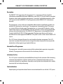
EMBLEM™ S-ICD PROGRAMMER: general description
Description
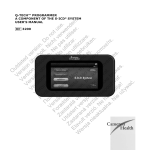
The EMBLEM™ S-ICD programmer (the “programmer”) is a component of Boston Scientific’s
subcutaneous implantable cardioverter defibrillator system (the S-ICD System) which is prescribed
for patients when cardiac arrhythmia management is warranted. Implantable components of the
S-ICD System include the EMBLEM S-ICD pulse generator and the EMBLEM S-ICD subcutaneous
electrode.
The programmer is a non–sterile, non–implantable, tablet computer controlled by a graphic user
interface (GUI) displayed on a touchscreen. The programmer is powered by either AC line power
or an internal lithium ion battery pack. The programmer uses a connected RF telemetry wand to
communicate wirelessly with the EMBLEM S-ICD pulse generator in order to adjust programmable
settings and to collect patient data. The EMBLEM S-ICD programmer is also compatible with the
Cameron Health Model 1010 SQ-RX pulse generator. The programmer features and functions
described in this manual apply to the EMBLEM S-ICD System as well as to the Cameron Health S-ICD
System.
The S-ICD System is designed for ease of use and simplicity of patient management. The S-ICD
System has a number of automatic functions designed to reduce the amount of time required for
implantation, initial programming and patient follow-up.
Intended Use of Programmer
The programmer is intended to communicate with the implanted pulse generator using wireless
telemetry. The programmer software controls all such telemetry functions.
Indications for Use
The S-ICD System is intended to provide defibrillation therapy for the treatment of life-threatening
ventricular tachyarrhythmias in patients who do not have symptomatic bradycardia, incessant
ventricular tachycardia, or spontaneous, frequently recurring ventricular tachycardia that is reliably
terminated with anti-tachycardia pacing.
Contraindications
Unipolar pacing and impedance-based features are contraindicated for use with the S-ICD System.
1
EMBLEM™ S-ICD PROGRAMMER: general description
Related Information
Before using the S-ICD system, read and follow all instructions, warnings, and precautions provided
in this manual and in the manuals for the other system components. Manuals for the other system
components are listed below.
•
EMBLEM S-ICD Pulse Generator User’s Manual (or, for Cameron Health devices, SQ-RX Pulse
Generator User’s Manual)
•
EMBLEM S-ICD Subcutaneous Electrode User’s Manual
•
EMBLEM S-ICD Subcutaneous Electrode Insertion Tool User’s Manual
Programmer Warnings and Precautions
The following warnings and precautions apply specifically to the Model 3200 programmer
component of the S-ICD System.
Programmer Warnings
General
•
•
•
•
•
1
2
Modifications. No modification of this equipment is allowed unless approved by Boston
Scientific.
Programmer is MR Unsafe. The programmer is MR Unsafe and must remain outside the
MRI site Zone III (and higher) as defined by the American College of Radiology Guidance
Document for Safe MR Practices1. Under no circumstances should the programmer be
brought into the MRI scanner room, the control room, or the MRI site Zone III or IV areas.
High temperatures. Do not subject the programmer to temperatures outside of the -10°
C to 55° C (14° F to 131° F) storage range. Exposure to high temperatures may cause the
programmer to overheat or ignite, and may possibly reduce its performance and service life.
Extreme temperatures. Do not discard the programmer in a fire, incinerate, or subject it to
temperatures that exceed 100° C (212° F). This could cause the programmer to explode.
Do not immerse. Do not immerse the programmer in liquid of any kind. If the programmer
does get wet, contact customer service for information about returning the programmer to
Boston Scientific. Do not attempt to dry the programmer in an oven, microwave, or dryer
because this poses a risk of overheating or explosion.
Kanal E, et al., American Journal of Roentgenology 188:1447-74, 2007.
EMBLEM™ S-ICD PROGRAMMER: general description
Conditions for Operation
•
•
•
•
•
•
•
Use only the supplied external power supply. Use the programmer only with the external
power supply packaged with the programmer. Using other power supplies may cause
damage to the programmer.
Electric shock. To avoid risk of electric shock, the programmer’s external power supply must
only be connected to a grounded electrical outlet.
Damaged programmer or power supply. Never use a damaged external power supply
or a damaged programmer. Doing so could result in user injury, patient injury, or a lack of
therapy delivery.
Interference with nearby equipment. By design, the programmer emits radio frequencies
in the 402-405 MHz and 2.4 GHz bands. This may interfere with nearby medical or office
equipment. When using the programmer, closely monitor equipment in the vicinity to verify
normal operation. It may be necessary to take mitigation measures, such as reorienting or
relocating the programmer or shielding the location.
Interference with programmer communication. The presence of other equipment
operating in the same frequency bands used by the programmer (402-405 MHz for the
pulse generator and 2.4 GHz for the printer) may interfere with communication. Interference
can occur even if the other equipment complies with the International Special Committee
on Radio Interference (CISPR) emission requirements. This RF interference can be reduced
by increasing the distance between the interfering device and the programmer and pulse
generator or printer. If communication problems persist, refer to the Troubleshooting
section of this manual.
Use of non-approved accessories. The use of any accessories with the programmer other
than those specified by Boston Scientific in this manual may result in increased emissions
or decreased immunity of the programmer and may cause decreased functionality or
unintended operational behavior of the programmer. Anyone connecting such accessories
to the programmer may be configuring a medical system and is responsible to ensure
that the system complies with the requirements of IEC/EN 60601-1, Clause 16 for medical
electrical systems.
Programmer location. Do not use the programmer adjacent to or stacked with other
equipment. If adjacent or stacked use is necessary, check the programmer for normal
operation in that configuration.
3
EMBLEM™ S-ICD PROGRAMMER: general description
Programmer Precautions
General
•
•
•
•
Wand use. Use only the Model 3203 telemetry wand with the programmer.
Do not disassemble. Do not disassemble or alter any parts of the programmer.
Device communication. Use only the designated Boston Scientific programmer and
appropriate software application to communicate with the S-ICD pulse generator.
Intended users. The programmer is intended for use by or under the direction of healthcare
professionals only.
Storage and Handling
•
•
•
Mishandling. Mishandling (such as dropping or crushing) could damage the programmer.
If you suspect damage to the programmer, contact your Boston Scientific representative or
the customer service department for instructions and return packaging.
Broken or cracked screen. The display on the programmer is made of glass or acrylic and
could break if the programmer is dropped or if it receives significant impact. Do not use if
screen is broken or cracked as this could cause injury.
Magnet handling. Do not place a magnet on the programmer.
Implantation
•
•
Telemetry wand. The wand is a non-sterile device. Do not sterilize the wand. The wand
must be contained in a sterile barrier before use in the sterile field.
Programmer must remain outside the sterile field. The programmer is non-sterile and
cannot be sterilized. It must remain outside the sterile field.
Conditions for operation
•
•
•
4
Disconnecting the programmer. Mains isolation is achieved by disconnecting the external
power supply power cord from the AC electrical outlet. Do not position the programmer or
the external power supply in a manner that would make it difficult to disconnect that cord.
Programmer use. The programmer is not waterproof or explosion-proof and cannot be
sterilized. Do not use it in the presence of flammable gas mixtures containing anesthetics,
oxygen, or nitrous oxide.
Confirm communication. Confirm that the programmer is in communication with the
intended implanted S-ICD pulse generator.
EMBLEM™ S-ICD PROGRAMMER: general description
•
Electrostatic discharge. The programmer may be affected by ESD. If ESD occurs and the
programmer’s functionality is affected, attempt to reset the programmer or contact Boston
Scientific for instructions. Do not touch or connect the telemetry wand to the programmer
unless ESD precautionary procedures are used.
S-ICD System Warnings and Precautions
The following warnings and precautions apply to the S-ICD System as a whole. For additional
warnings and precautions that are specific to other individual components of the system, and/or to
the process of implanting the system, refer to the manual of the relevant system component (pulse
generator, subcutaneous electrode, or electrode insertion tool [EIT]).
S-ICD System Warnings
General
•
•
•
Component Compatibility. All Boston Scientific S-ICD implantable components are
designed for use with the Boston Scientific or Cameron Health S-ICD System only.
Connection of any S-ICD System components to a non-compatible component will result in
failure to deliver life-saving defibrillation therapy.
Backup defibrillation protection. Always have external defibrillation equipment and
medical personnel skilled in CPR available during implant and follow up testing. If not
terminated in a timely fashion, an induced ventricular tachyarrhythmia can result in the
patient’s death.
Pulse generator interaction. Using multiple pulse generators could cause pulse generator
interaction, resulting in patient injury or a lack of therapy delivery. Test each system
individually and in combination to help prevent undesirable interactions. Refer to the
appropriate S-ICD pulse generator manual for more information.
Post-Implant
•
•
Magnet Response. Use caution when placing a magnet over the S-ICD pulse generator
because it suspends arrhythmia detection and therapy response. Removing the magnet
resumes arrhythmia detection and therapy response.
Magnet response with deep implant placement. In patients with a deep implant
placement (greater distance between the magnet and the pulse generator) magnet
5
EMBLEM™ S-ICD PROGRAMMER: general description
•
•
•
•
application may fail to elicit the magnet response. In this case the magnet cannot be used to
inhibit therapy.
Diathermy. Do not expose a patient with an implanted S-ICD System to diathermy. The
interaction of diathermy therapy with an implanted S-ICD pulse generator or electrode can
damage the pulse generator and cause patient injury.
Magnetic Resonance Imaging (MRI) exposure. Do not expose a patient to MRI scanning.
Strong magnetic fields may damage the pulse generator and/or subcutaneous electrode,
possibly resulting in injury to or death of the patient.
Protected environments. Advise patients to seek medical guidance before entering
environments that could adversely affect the operation of the active implantable medical
device, including areas protected by a warning notice that prevents entry by patients who
have a pulse generator.
Sensitivity settings and EMI. The pulse generator may be more susceptible to low
frequency electromagnetic interference at induced signals greater than 80 uV. Oversensing
of noise due to this increased susceptibility could lead to inappropriate shocks and
should be taken into consideration when determining the follow-up schedule for patients
exposed to low frequency electromagnetic interference. The most common source
of electromagnetic interference in this frequency range is the power system for some
European trains which operate at 16.6 Hz. Particular attention should be given to patients
with occupational exposure to these types of systems.
Clinical Considerations
•
•
•
Longevity. Battery depletion will eventually cause the S-ICD pulse generator to stop
functioning. Defibrillation and excessive numbers of charging cycles shorten the battery
longevity.
Pediatric Use. The S-ICD System has not been evaluated for pediatric use.
Available Therapies. The S-ICD System does not provide long-term bradycardia pacing,
Cardiac Resynchronization Therapy (CRT) or Anti-Tachycardia Pacing (ATP).
Implantation
•
6
Avoid shock at implant. Verify the device is in Shelf mode or Therapy Off to prevent the
delivery of unwanted shocks to the patient or the person handling the device during the
implant procedure.
EMBLEM™ S-ICD PROGRAMMER: general description
Device Programming
•
•
•
Sensing adjustment. Following any sensing parameter adjustment or any modification of
the subcutaneous electrode, always verify appropriate sensing.
Patients hear tones coming from their devices. Patients should be advised to contact
their physician immediately whenever they hear beeping tones coming from their device.
Programming for supraventricular tachyarrhythmias (SVTs). Determine if the device and
programmed parameters are appropriate for patients with SVTs because SVTs can initiate
unwanted device therapy.
S-ICD System Precautions
Environmental and Medical Therapy Hazards
•
Avoid electromagnetic interference (EMI). Advise patients to avoid sources of EMI
because EMI may cause the pulse generator to deliver inappropriate therapy or inhibit
appropriate therapy. Moving away from the source of the EMI or turning off the source
usually allows the pulse generator to return to normal operation. Examples of potential EMI
sources found in hospital and medical environments are:
»» Radio transmitters
»»
Electronic surveillance or security systems
»»
Medical treatments and diagnostic tests in which an electrical current is passed
through the body, such as TENS, electrocautery, electrolysis/thermolysis, electrodiagnostic testing, electromyography,or nerve conduction studies
»»
Any externally applied device that uses an automatic lead detection alarm system (e.g.,
an EKG machine)
Hospital and Medical Environments
•
External defibrillation. External defibrillation or cardioversion can damage the pulse
generator or subcutaneous electrode. To help prevent damage to implanted system
components, consider the following:
»» Avoid placing a pad (or paddle) directly over the pulse generator or subcutaneous
electrode. Position the pads (or paddles) as far from the implanted system components as possible.
»»
Set energy output of external defibrillation equipment as low as clinically acceptable.
7
EMBLEM™ S-ICD PROGRAMMER: general description
»»
•
•
•
Following external cardioversion or defibrillation, verify pulse generator function
(“Post-Therapy Pulse Generator Follow-Up” on page 13).
Cardiopulmonary resuscitation. Cardiopulmonary resuscitation (CPR) may temporarily
interfere with sensing and may cause delay of therapy.
Electrical interference. Electrical interference or “noise” from devices such as electrocautery
and monitoring equipment may interfere with establishing or maintaining telemetry for
interrogating or programming the device. In the presence of such interference, move the
programmer away from electrical devices, and ensure that the wand cord and cables are
not crossing one another. Electrical interference or “noise” from concomitant implanted
devices such as a ventricular assist device (VAD), drug pump, or insulin pump may interfere
with establishing or maintaining telemetry for interrogating or programming the pulse
generator. In the presence of such interference, place the wand over the pulse generator
and shield both with a radiation-resistant material.
Ionizing Radiation. It is not possible to specify a safe radiation dosage or guarantee
proper pulse generator function following exposure to ionizing radiation. Multiple factors
collectively determine the impact of radiation therapy on an implanted pulse generator,
including proximity of the pulse generator to the radiation beam, type and energy level of
the radiation beam, dose rate, total dose delivered over the life of the pulse generator, and
shielding of the pulse generator. The impact of ionizing radiation will also vary from one
pulse generator to another and may range from no changes in function to a loss of therapy.
Sources of ionizing radiation vary significantly in their potential impact on an implanted
pulse generator. Several therapeutic radiation sources are capable of interfering with or
damaging an implanted pulse generator, including those used for the treatment of cancer,
such as radioactive cobalt, linear accelerators, radioactive seeds, and betatrons. Prior to a
course of therapeutic radiation treatment, the patient’s radiation oncologist and cardiologist
or electrophysiologist should consider all patient management options, including increased
follow-up and device replacement.
Other considerations include:
»» Shield the pulse generator with a radiation-resistant material, regardless of the distance between the pulse generator and the radiation beam.
»»
Determining the appropriate level of patient monitoring during treatment
Evaluate pulse generator operation during and following the course of radiation treatment
to exercise as much device functionality as possible (“Post-Therapy Pulse Generator Follow
8
EMBLEM™ S-ICD PROGRAMMER: general description
Up” on page 13). The extent, timing, and frequency of this evaluation relative to the
radiation therapy regimen are dependent upon current patient health, and therefore should
be determined by the attending cardiologist or electrophysiologist.
•
Pulse generator diagnostics are performed automatically once per hour, so pulse generator
evaluation should not be concluded until pulse generator diagnostics have been updated
and reviewed (at least one hour after radiation exposure). The effects of radiation exposure
on the implanted pulse generator may remain undetected until some time following
exposure. For this reason, continue to monitor pulse generator function closely and use
caution when programming a feature in the weeks or months following radiation therapy.
Electrocautery and Radio Frequency (RF) Ablation. Electrocautery and RF ablation may
induce ventricular arrhythmias and/or fibrillation, and may cause inappropriate shocks and
inhibition of post-shock pacing. Additionally, exercise caution when performing any other
type of cardiac ablation procedure in patients with implanted devices. If electrocautery or
RF ablation is medically necessary, observe the following to minimize risk to the patient and
device:
»» Program the pulse generator to Therapy Off mode.
»»
Have external defibrillation equipment available.
»»
Avoid direct contact between the electrocautery equipment or ablation catheters and
the pulse generator and subcutaneous electrode.
»»
Keep the path of the electrical current as far away as possible from the pulse generator
and subcutaneous electrode.
»»
If RF ablation and/or electrocautery is performed on tissue near the device or subcutaneous electrode, verify pulse generator function (“Post-Therapy Pulse Generator Follow Up” on page 13. For electrocautery, use a bipolar electrocautery system where
possible and use short, intermittent, and irregular bursts at the lowest feasible energy
levels.
When the procedure is finished, return the pulse generator to Therapy On mode.
•
Lithotripsy. Extracorporeal shock wave lithotripsy (ESWL) may cause electromagnetic
interference with or damage to the pulse generator. If ESWL is medically necessary, consider
the following to minimize the potential for encountering interaction:
»» Avoid focusing the lithotripsy beam near the pulse generator implant site.
»»
Program the pulse generator to Therapy Off mode to prevent inappropriate shocks.
9
EMBLEM™ S-ICD PROGRAMMER: general description
•
•
•
Ultrasound energy. Therapeutic ultrasound (e.g., lithotripsy) energy may damage the pulse
generator. If therapeutic ultrasound energy must be used, avoid focusing near the pulse
generator site. Diagnostic ultrasound (e.g., echocardiography) is not known to be harmful to
the pulse generator.
Conducted electrical current. Any medical equipment, treatment, therapy, or diagnostic
test that introduces electrical current into the patient has the potential to interfere
with pulse generator function. Medical therapies, treatments, and diagnostic tests that
use conducted electrical current (e.g., TENS, electrocautery, electrolysis/thermolysis,
electrodiagnostic testing, electromyography, or nerve conduction studies) may interfere
with or damage the pulse generator. Program the device to Therapy Off mode prior to the
treatment, and monitor device performance during the treatment. After the treatment,
verify pulse generator function (“Post-Therapy Pulse Generator Follow Up” on page 13).
Transcutaneous Electrical Nerve Stimulation (TENS). TENS involves passing electrical
current through the body, and may interfere with pulse generator function. If TENS is
medically necessary, evaluate the TENS therapy settings for compatibility with the pulse
generator. The following guidelines may reduce the likelihood of interaction:
»» Place the TENS electrodes as close together and as far away from the pulse generator
and subcutaneous electrode as possible.
»»
Use the lowest clinically-appropriate TENS energy output.
»»
Consider cardiac monitoring during TENS use. Additional steps can be taken to help
reduce interference during in-clinic use of TENS:
»»
If interference is suspected during in-clinic use, turn off the TENS unit.
Do not change TENS settings until you have verified that the new settings do not interfere
with pulse generator function.
If TENS is medically necessary outside the clinical setting (at-home use), provide patients
with the following instructions:
10
»»
Do not change the TENS settings or electrode positions unless instructed to do so.
»»
End each TENS session by turning off the unit before removing the electrodes.
»»
If the patient receives a shock during TENS use, they should turn off the TENS unit and
contact their physician. Follow these steps to use the programmer to evaluate pulse
generator function during TENS use:
EMBLEM™ S-ICD PROGRAMMER: general description
1. Program the pulse generator to Therapy Off mode.
2. Observe real-time EGMs at prescribed TENS output settings, noting when
appropriate sensing or interference occurs.
3. When finished, turn off the TENS unit and reprogram the pulse generator to Therapy
On mode.
You should also perform a thorough follow-up evaluation of the pulse generator following
TENS, to ensure that device function has not been compromised (“Post-Therapy Pulse
Generator Follow Up” on page 13). For additional information, contact Boston Scientific
using the information on the back cover.
•
•
Electronic Article Surveillance (EAS) and Security Systems. Advise patients how to avoid
impact to cardiac device function due to antitheft and security gates, tag deactivators, or
tag readers that include radio frequency identification (RFID) equipment. These systems
may be found at the entrances and exits of stores, at checkout counters, in public libraries,
and in point-of-entry access control systems. Patients should avoid lingering near or
leaning against antitheft and security gates and tag readers. In addition, patients should
avoid leaning against checkout counter-mounted and handheld tag deactivation systems.
Antitheft gates, security gates, and entry control systems are unlikely to affect cardiac
device function when patients walk through them at a normal pace. If the patient is near
an electronic antitheft, security, or entry control system and experiences symptoms, they
should promptly move away from nearby equipment and inform their doctor.
Elevated Pressures. The International Standards Organization (ISO) has not approved a
standardized pressure test for implantable pulse generators that experience hyperbaric
oxygen therapy (HBOT). Elevated pressures due to HBOT may damage the pulse
generator. Prior to starting an HBOT program, the patient’s attending cardiologist or
electrophysiologist should be consulted to fully understand the potential consequences
relative to the patient’s specific health condition. More frequent device follow-up may
be warranted in conjunction with HBOT. Evaluate pulse generator operation following
high pressure exposure (“Post-Therapy Pulse Generator Follow-Up” on page 13). The
extent, timing, and frequency of this evaluation relative to the high pressure exposure
are dependent upon current patient health, and should be determined by the attending
cardiologist or electrophysiologist. Refer to the appropriate pulse generator manual for
additional information about device-specific high pressure testing results. If you have
additional questions, contact Boston Scientific using the information on the back cover.
11
EMBLEM™ S-ICD PROGRAMMER: general description
Follow-up Testing
•
•
•
Low shock impedance. A reported shock impedance value of less than 25 ohms from a
delivered shock could indicate a problem with the device. The delivered shock may have
been compromised, and/or any future therapy from the device may be compromised. If
a reported impedance value of less than 25 ohms is observed, correct functioning of the
device should be verified.
Conversion testing. Successful VF or VT conversion during arrhythmia conversion testing
is no assurance that conversion will occur post-operatively. Be aware that changes in the
patient’s condition, drug regimen, and other factors may change the DFT, which may result
in nonconversion of the arrhythmia post-operatively. Verify with a conversion test that the
patient’s tachyarrhythmias can be detected and terminated by the pulse generator system if
the patient’s status has changed or parameters have been reprogrammed.
Follow-up considerations for patients leaving the country. Pulse generator follow-up
considerations should be made in advance for patients who plan to travel or relocate postimplant to a country other than the country in which their device was implanted. Regulatory
approval status for devices and associated programmer software configurations varies by
country; certain countries may not have approval or capability to follow specific products.
Contact Boston Scientific, using the information on the back cover, for help in determining
feasibility of device follow-up in the patient’s destination country.
Explant and Disposal
•
12
Device handling at explant. Before explanting, cleaning, or shipping the device, complete
the following actions to prevent unwanted shocks, overwriting of important therapy history
data, and audible tones:
»» Program the pulse generator to Therapy Off mode
»»
If ERI or EOL has been reached, disable the beeper.
»»
Clean and disinfect the device using standard biohazard handling techniques.
EMBLEM™ S-ICD PROGRAMMER: general description
Supplemental Precautionary Information
•
Post-Therapy Pulse Generator Follow Up. Following any surgery or medical procedure
with the potential to affect pulse generator function, you should perform a thorough follow
up, which may include the following:
»» Interrogating the pulse generator with a programmer
»»
Reviewing stored events, fault codes, and real-time S-ECGs prior to saving all patient
data
»»
Testing the subcutaneous electrode impedance
»»
Verifying battery status
»»
Printing any desired reports
»»
Verifying the appropriate final programming prior to allowing the patient to leave the
clinic
»»
Ending session
S-ICD System Clinical Investigation
A summary of the S-ICD System Clinical Investigation, including observed adverse events, is
provided in the S-ICD pulse generator user’s manual.
Potential Adverse Events
Potential adverse events related to implantation of the S-ICD System may include, but are not
limited to, the following:
•
Acceleration/induction of atrial or ventricular arrhythmia
•
Adverse reaction to induction testing
•
Allergic/adverse reaction to system or medication
•
Bleeding
•
Conductor fracture
•
Cyst formation
•
Death
•
Delayed therapy delivery
13
EMBLEM™ S-ICD PROGRAMMER: general description
14
•
Discomfort or prolonged healing of incision
•
Electrode deformation and/or breakage
•
Electrode insulation failure
•
Erosion/extrusion
•
Failure to deliver therapy
•
Fever
•
Hematoma/seroma
•
Hemothorax
•
Improper electrode connection to the pulse generator
•
Inability to communicate with the pulse generator
•
Inability to defibrillate or pace
•
Inappropriate post-shock pacing
•
Inappropriate shock delivery
•
Infection
•
Keloid formation
•
Migration or dislodgement
•
Muscle/nerve stimulation
•
Nerve damage
•
Pneumothorax
•
Post-shock/post-pace discomfort
•
Premature battery depletion
•
Random component failures
•
Stroke
•
Subcutaneous emphysema
•
Surgical revision or replacement of the system
•
Syncope
•
Tissue redness, irritation, numbness or necrosis
EMBLEM™ S-ICD PROGRAMMER: general description
If any adverse events occur, invasive corrective action and/or S-ICD System modification or removal
may be required.
Patients who receive an S-ICD System may also develop psychological disorders that include, but
are not limited to, the following:
•
Depression/anxiety
•
Fear of device malfunction
•
Fear of shocks
•
Phantom shocks
15
EMBLEM™ S-ICD PROGRAMMER: Operation
Programmer Setup
Packaging
Programmer components include:
•
Model 3200 Programmer with pre-loaded software
•
Model 3203 Telemetry Wand
•
Model 3204 External power supply and AC power cord
Visually inspect the packaging to ensure the contents are complete. Do not use if there is evidence
of damage.
In case of damage return the product to Boston Scientific. For return packaging and instructions,
contact Boston Scientific using the information on the back cover of this manual.
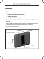
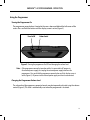
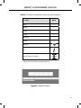
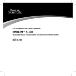
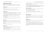
Programmer Controls and Connections
Volume control
Power button
Telemetry wand connector port
External power supply port
microSD™ slot
Figure 1: Controls and external connections
16
EMBLEM™ S-ICD PROGRAMMER: Operation
Charging the Programmer
The programmer is primarily intended to be operated while connected to the AC-powered external
power supply, but may also be operated on battery power provided that the internal battery is
adequately charged. The programmer is recharged whenever it is connected to the AC-powered
external power supply. When not in use, it is recommended that the programmer remain connected
to the external power supply in order to maintain an adequate battery charge.
Note: Current session data may be lost if a 45 minute period of inactivity occurs during an
active telemetry session and the programmer is not connected to AC power.
Typical charge time for a fully discharged battery is 5 hours. However, more time may be required if
the programmer is in use while being recharged.
The Battery Status indicator located on the upper right corner of the screen displays the status of
the main battery power when the unit is in use:
•
All four bars are illuminated (green) – The battery is 100% charged
•
Three bars are illuminated (green) – The battery is 75% charged
•
Two bars are illuminated (yellow) – The battery is 50% charged
•
One bar is illuminated (red) – The battery is 25% charged
The programmer displays one of the following alert screens as battery power gets progressively
lower.
•
Programmer Battery Low
•
Programmer Battery Critical
•
Out Of Power
To charge the programmer:
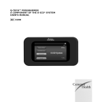
1. Connect the external power supply cable to the programmer (Figure 2).
2. Plug the external power supply cord into an AC power outlet.
Warning: Use the programmer only with the external power supply packaged with the
programmer. Using other power supplies may cause damage to the programmer.
Warning: To avoid risk of electric shock, the programmer’s external power supply must only be
connected to a grounded electrical outlet.
17
EMBLEM™ S-ICD PROGRAMMER: Operation
External power supply port
Figure 2: Connecting the external power supply
18
EMBLEM™ S-ICD PROGRAMMER: Operation
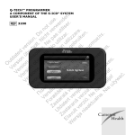
Using the Programmer
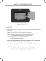
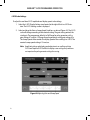
Turning the Programmer On
The programmer power button is located in the recess above and behind the left corner of the
screen. Press and hold the button until the display screen is active (Figure 3).
Power On/Off
Volume Control
Figure 3: Turning the programmer On/Off and changing the volume level
Note: If the programmer cannot be turned on while it is connected to AC power via
the external power supply, first unplug the external power supply cord from the
programmer. Press and hold the programmer power button until the display screen is
active (Figure 3). AC power via the external power supply can then be reconnected.
Changing the Programmer Volume Level
The volume level of programmer-generated sounds may be temporarily adjusted using the volume
control (Figure 3). This level is automatically reset when the programmer is restarted.
19
EMBLEM™ S-ICD PROGRAMMER: Operation
Placing the Programmer in Suspend Mode
The programmer has a Suspend Mode which is activated automatically to conserve power. The
display will be blank when this mode is in effect.
The programmer enters Suspend Mode whenever:
•
The power button (Figure 3) is momentarily pressed and released
•
The programmer is not connected to the external power supply, it is not in active
communication with an S-ICD pulse generator, and no user activity has occurred for 15 minutes
Momentarily pressing the power button will resume normal operation.
Turning the Programmer Off
There are two ways to turn the programmer off:
1. Press and hold the power button (Figure 2) until the System shutdown menu
appears. Select Power off from the popup and confirm by pressing OK.
2. From the programmer start-up screen, press the Power Off button and select OK at the
confirmation prompt.
Using the Programmer Touch Screen
The programmer is equipped with an LCD touch screen. The screen can be adjusted to the desired
viewing angle by using the kick-stand located on the back of the programmer. All interaction with
the programmer is conducted using the fingers to touch the appropriate areas on the screen.
Scroll on-screen lists by sliding a finger up and down the list (Figure 4). An on-screen keyboard is
presented whenever text entry is required.
Caution: The display on the programmer is made of glass or acrylic and could
break if the programmer is dropped or if it receives significant impact.
Do not use if screen is broken or cracked as this could cause injury.
20
EMBLEM™ S-ICD PROGRAMMER: Operation
Figure 4: Scrolling on-screen lists
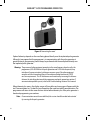
Using the Wand
The Model 3203 wand (“the wand”) makes it possible for this programmer to communicate with the
pulse generator.
Caution: Use only the Model 3203 telemetry wand with the programmer.
Caution: The wand is a non-sterile device. Do not sterilize the wand. The wand
must be contained in a sterile barrier before use in the sterile field
Caution: The programmer is non-sterile and cannot be sterilized.
It must remain outside the sterile field.
To connect the wand to the programmer, slide the wand cable connector over the communication
connector port located on the rear edge of the programmer (Figure 5).
To disconnect the wand, grasp the wand cable connector and gently pull it straight off the
communication connector port.
Note: Do not pull or yank on the cable to disconnect the wand from the programmer. Such
action could cause hidden damage to the cable. A damaged cable might reduce
wireless communication capabilities and require a replacement wand.
21
EMBLEM™ S-ICD PROGRAMMER: Operation
Figure 5: Connecting the wand
Optimal telemetry depends on the wand being placed directly over the implanted pulse generator.
Although it may appear that the programmer is in communication with the pulse generator at
greater distances, programming should always be performed with the wand placed directly over
the implanted pulse generator.
Warning: The presence of other equipment operating in the same frequency bands used by the
programmer (402-405 MHz for the pulse generator and 2.4 GHz for the printer) may
interfere with communication. Interference can occur even if the other equipment
complies with the International Special Committee on Radio Interference (CISPR)
emission requirements. This RF interference can be reduced by increasing the distance
between the interfering device and the programmer and pulse generator or printer. If
communication problems persist, refer to the Troubleshooting section of this manual.
When telemetry loss occurs, the display screen will turn yellow and a message will appear with the
text “Communication Loss” to alert the user. Reposition the wand to establish communication. The
programmer will return to the screen that was active before telemetry loss if the pulse generator is
found and programming can continue.
Note: If communication cannot be reestablished, the session should be ended and restarted
by scanning for the pulse generator.
22
EMBLEM™ S-ICD PROGRAMMER: Operation
Navigation
The programmer’s graphic user interface (GUI) facilitates management and control of the S-ICD
System. The Navigation Bar and on-screen icons at the top of the screen allow the user to navigate
programming software screens. In addition, a continuous subcutaneous electrocardiogram (S-ECG)
is displayed along the bottom of the screen during Online (active) communication with the pulse
generator.
Screen Header
When the programmer is Offline (inactive communication), the screen header displays the Battery
Status Indicator.
When viewing Offline Stored Sessions, the screen header displays:
• Patient name
• Therapy On/Off
• Battery status indicator
When the programmer is Online (active communication), the screen header displays:
• Therapy On/Off
• Patient name
• Patient heart rate
• Programmer Battery and Telemetry status indicator
• Screen title
•
Rescue shock icon
Navigation Bar
The Navigation Bar is the primary method for navigating the Online programmer screens. The bar
is located along the top edge of the programmer screen and chosen screens appear with their
selection icon highlighted.
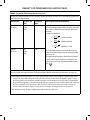
Table 1 (page 25) provides a list of the programmer icons and their corresponding descriptions.
23
EMBLEM™ S-ICD PROGRAMMER: Operation
Restarting the Programmer
The programmer’s operating system is self-monitoring and is generally able to sense many system
error conditions and automatically initiate a restart sequence in response. Follow the on-screen
instructions to complete the programmer-initiated restart sequence.
The programmer may need to be manually restarted if:
• You cannot exit a screen
• The operating system stops responding
A manual restart is accomplished by pressing and holding the power button until the system
shutdown menu appears on the screen. Select Restart from the popup and confirm
by pressing OK.
If the programmer does not respond to a restart process, contact Boston Scientific using the
information on the back cover of this manual.
24
EMBLEM™ S-ICD PROGRAMMER: Operation
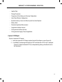
Table 1: Icon descriptions
Icon
Description
User Application

Main Menu Icon
Allows user to return to the main menu.

Automatic Setup Icon
Allows user to access the Automatic Setup menu.

Device Settings Icon
Allows user to access the S-ICD device settings screen.

Device Status Icon (open folder and closed folder)
Allows user to access the S-ICD device status screen. User can view number of shocks
delivered since the last update as well as the S-ICD device battery life.

Patient View Icon
Allows user to access the patient chart screen.

Captured and Stored Episodes S-ECG Icon
Allows user to access captured S-ECG and stored episode screens.

Induction Test Icon
Allows user to access induction screen.

Manual Shock Icon
Allows user to access the manual shock screen.

Battery & Telemetry Meter
Left side of the meter allows user to view the programmer’s battery status.
The right side of the meter allows viewing of telemetry signal strength.

Capture S-ECG
Allows user to capture a live S-ECG.

S-ECG Display Settings
Allows user to modify the zoom and sweep speed on the live S-ECG.

Heart Rate Icon
Allows user to view current heart rate.

Rescue Shock Icon
Allows user to administer a rescue shock
Option Selection Slider Switch
Allows user to select one of two options, e.g. A or B
25
EMBLEM™ S-ICD PROGRAMMER: Operation
Configuring the Programmer
Configuring Programmer Settings
The programmer should be configured before communication with a pulse generator is attempted.
This includes setting the date and time format, time zone, language and printer. Once these settings
are configured during the initial setup process they become the default parameters and will not
normally need to be changed with each session.
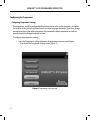
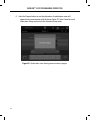
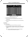
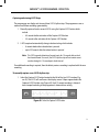
To configure the programmer settings:
1. Select the Programmer Settings button on the programmer start-up screen (Figure
6) to display the Programmer Settings screen (Figure 7).
Figure 6: Programmer start-up screen
26
EMBLEM™ S-ICD PROGRAMMER: Operation
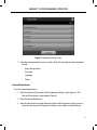
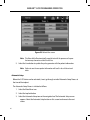
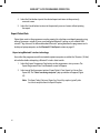
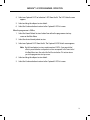
Figure 7: Programmer Settings screen
2. Select the corresponding line to access each setting. The settings that can be configured
include:
•
Date and time format
•
Time zone
•
Language
•
Printer
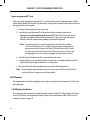
Date and Time Format
To set the date and time format:
1. Select Set Date and Time Format on the Programmer Settings screen (Figure 7). The
Date and Time Settings screen appears (Figure 8).
2. Select the desired date format.
3. Select the Save button to save the changes and return to the Programmer Settings screen, or
select Cancel to return to the Programmer Settings screen without saving the changes.
27
EMBLEM™ S-ICD PROGRAMMER: Operation
Figure 8: Date and Time Settings screen
Time Zone
The time zone setting controls two S-ICD System parameters, one for the programmer (the time
shown on screens and printed reports), the other for pulse generators (the electronic filter that is
intended to minimize electromagnetic interference {EMI}).
Choosing the correct time zone setting for the programmer will result in the electronic filter of
interrogated pulse generators being set to the appropriate regional electrical power line frequency.
Specifically, the pulse generator line frequency filter is automatically programmed to either 50 Hz or
60 Hz, based on the time zone setting of the interrogating programmer.
To set the time zone
1. Select Set Time Zone on the Programmer Settings screen. The time zone selection
screen appears (Figure 9).
2. Select the time zone button for the zone in which the programmer will be used. A
checkmark will appear in the selected button.
3. Select the Save button to save the changes and return to the Programmer Settings
screen, or select Cancel to return to the Programmer Settings screen without saving
the changes.
28
EMBLEM™ S-ICD PROGRAMMER: Operation
In the rare cases where a single time zone setting includes regional power line frequency
differences, two line frequency options are available. Choose the option with the correct frequency
for the region where the programmer is located (for example see the top two rows in Figure 9.)
Because a programmer will set the time zone (and electronic frequency filter) of pulse generators it
interrogates to match its own time zone setting, be aware that travelling patients whose devices are
interrogated in time zones or countries other than the one in which they reside may need to have
their pulse generator time zone reset upon returning home.
Figure 9: Time Zone selection screen (scrollable list)
Language Preference
To set the language preference:
1. Select Set Language on the Programmer Settings screen. The Language Settings
screen appears. Scroll the list and select a language.
2. Select the Save button to save the changes or select Cancel to return to the
Programmer Settings screen without saving the changes. If the language is changed
the programmer will automatically restart and return to the Startup screen.
29
EMBLEM™ S-ICD PROGRAMMER: Operation
Printer Selection
The programmer communicates with the printer via Bluetooth® wireless technology. Only Boston
Scientific-approved printers can be paired and used with the programmer. To select the printer to
be paired and used with the programmer:
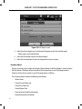
1. Ensure the printer is on and, depending on your specific printer, that the wireless
function is enabled or the wireless adapter is in the printer’s USB port.
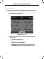
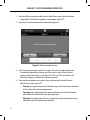
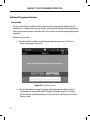
2. Select Printer Setup on the Programmer Settings screen. A previously configured printer
becomes the default printer and will be displayed at this time. If a default printer
has not already been selected and configured, the Printer Setup screen (Figure 10)
will be empty and the programmer will scan the area to locate wireless printers. A
Scan Progress Bar will appear informing the user that the programmer is currently
scanning for printers.
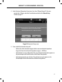
3. Select the printer of choice from among those found during the scan (Figure 10). If none
were found, a window will appear stating that there are no printers. Select the Try
Again button or the Cancel button to return to the Programmer Settings screen.
Figure 10: Printer Setup screen
30
EMBLEM™ S-ICD PROGRAMMER: Operation
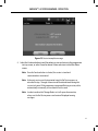
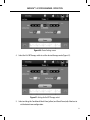
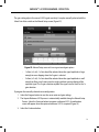
4. Select the desired printer from the list and enter the name using the on-screen
keyboard (up to 15 characters). A unique printer identifier should appear with the
printer selection (Figure 11).
Figure 11: Use the on-screen keyboard to enter a name for the selected printer
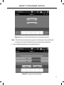
5. Select the Save button to save the changes and return to the Programmer Settings
screen, or select Cancel to return to the Programmer Settings screen without saving
the changes. A confirmation screen will appear when the printer setup is completed
(Figure 12).
Note: Refer to “Troubleshooting” section for information about printer problems.
31
EMBLEM™ S-ICD PROGRAMMER: Operation
Figure 12: Printer Setup confirmation screen
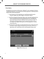
Bluetooth® Data Export
The programmer can be configured to wirelessly export patient data to desktop or notebook
computers that are equipped with Bluetooth® wireless technology. The programmer and each
computer must be individually paired in order to use the wireless data export function. The
procedure for pairing the programmer with a computer is different from the procedure used to pair
the programmer with the printer.
Note: Data transfer is supported for computers running Windows. The data transfer feature
is not available for tablets or smartphones.
1. Since the programmer searches for nearby computers during the pairing process,
the computer to be paired must first be made discoverable.
Note: Detailed instructions for accomplishing this are found in the Microsoft
Windows help files under the general heading of “Why can’t I connect my
Bluetooth device to my computer?”
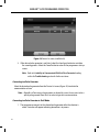
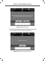
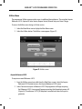
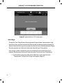
2. Once the target computer has been made discoverable, select the Export Programmer
Data button on the programmer start-up screen. The Export Programmer Data Over
Bluetooth screen will appear. Select the Set Up Authorized Computers button to scan
for nearby computers and begin the pairing process.
32
EMBLEM™ S-ICD PROGRAMMER: Operation
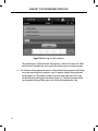
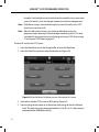
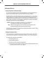
3. When the scan is complete the screen will list the discovered computers (the three
computers having the strongest Bluetooth® signals) under the heading Unauthorized
Computers Nearby (Figure 13). Choose the computer you wish to pair with and press
the plus button next to it to complete the pairing process.
4. During the pairing process, both the programmer and the computer will present
identical numeric passkeys and both machines will ask you to confirm that the two
numbers are the same. The passkey is only presented while pairing and is used to
verify that the correct machines are being paired.
5. Successful pairing is indicated when the listing for the subject computer appears in
the Authorized Computers column instead of the Unauthorized Computers Nearby
column.
6. Authorized computers may be renamed if desired. Press and hold the listing for the
computer until the Rename an Authorized Computer popup appears.
Figure 13: Choosing a computer to authorize for Bluetooth® data transfer
33
EMBLEM™ S-ICD PROGRAMMER: Operation
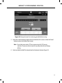
Programmer Software Version
To view the programmer’s software version:
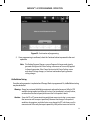
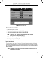
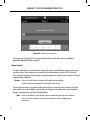
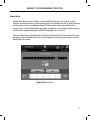
1. Select About Programmer on the Programmer Settings screen. The Programmer
Software Version information screen appears (Figure 14).
Figure 14: Programmer Software Version information screen
2. This screen displays the current version of the programmer software. Select the
Continue button to return to the Programmer Settings screen.
Note: The patient printed report also contains the programmer software version.
34
EMBLEM™ S-ICD PROGRAMMER: Operation
Programmer Modes of Operation
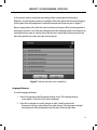
Online Behavior
The programmer’s interface varies according to whether the programmer is Online (actively
communicating) or Offline (not communicating) with a selected pulse generator.
An Online session begins when the programmer establishes a telemetry link with a specific pulse
generator. A yellow alert screen is displayed if the telemetry signal is lost between the programmer
and the pulse generator for more than five seconds during active communication. This may occur
if the wand is moved out of the telemetry communications range or if noise or interfering objects
inhibit communication. Programming commands, including Rescue Shocks, will not be available
until telemetry is reestablished.
Telemetry reconnection may occur automatically if the reason for the telemetry loss has been
remedied, e.g. moving the wand back into telemetry range of the pulse generator or removing the
source of interference or noise. Restart the session if the telemetry link does not resume within one
minute.
Note: Whenever the programmer is in active communication with a pulse generator,
charging of the pulse generator in preparation for delivering a shock (whether
commanded or in response to a detected arrhythmia) is indicated by an audible
notification. The notification continues until the shock is either delivered or aborted.
Offline Behavior
The programmer is Offline when it is not actively communicating with a pulse generator.
Programmer settings can be accessed and stored patient sessions can be viewed and/or printed
during Offline sessions.
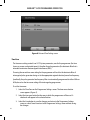
Stored Patient Sessions
During a patient follow-up visit, the programmer will retrieve data from the pulse generator
memory. The programmer can store up to 50 patient sessions. When the 51st session occurs, the
programmer will automatically replace the oldest stored session with the new data. A stored
session includes the following information:
•
•
•
•
Captured S-ECG Reports (including Induction S-ECGs)
Episode History (including any downloaded episodes)
Patient Data
Programmed Device Settings
35
EMBLEM™ S-ICD PROGRAMMER: Operation
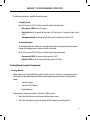
To view stored patient sessions:
1. From the programmer start-up screen, select Stored Patient Sessions.
2. Select the desired patient session.
Modes of Operation for the Pulse Generator
The pulse generator has three modes of operation:
•
Shelf
•
Therapy On
•
Therapy Off
Shelf Mode
The Shelf mode is a low power consumption state intended for storage only. When a pulse
generator in Shelf mode is interrogated by a programmer, it exits Shelf mode and defaults to
Therapy Off mode. A full-energy capacitor reformation is performed and the pulse generator
is prepared for set-up. Once the pulse generator is taken out of Shelf mode, it cannot be
reprogrammed back into Shelf mode.
Therapy On Mode
The Therapy On mode is the primary operating mode of the pulse generator, allowing automatic
detection of, and response to, ventricular tachyarrhythmias.
Therapy Off Mode
The Therapy Off mode disables automatic therapy delivery while still allowing manual control of
shock delivery. Programmable parameters may be viewed and adjusted via the programmer. The
subcutaneous electrogram (S-ECG) may be displayed or printed from this mode.
The pulse generator defaults to Therapy Off mode when it is taken out of Shelf mode.
Note: Manual and rescue shock therapy are available when the device is set to Therapy On
or Therapy Off mode and is actively communicating with a pulse generator, but only
after the initial Setup process is complete. Refer to Automatic Setup on page 46.
36
EMBLEM™ S-ICD PROGRAMMER: Operation
Connecting and Disconnecting from the S-ICD Pulse Generator
This section provides the information necessary for selecting, connecting to, and disconnecting from
the pulse generator.
Caution: Use only the designated Boston Scientific S-ICD programmer and appropriate
software application to communicate with and program the S-ICD pulse generator.
Scanning for Pulse Generators
1. Select the Scan For Devices button on the programmer start-up screen (Figure 15).
The Scan Progress Bar is displayed during the scanning process, at the conclusion
of which the Device List screen appears. Select the Cancel button at any time to
end the scanning process.
Figure 15: Programmer start-up screen
2. When the scanning process is complete, a list of all pulse generators detected (up to 16)
will be displayed on the Device List screen (Figure 16). The devices that are in Shelf
mode will be displayed as “Not Implanted.” Any devices that were previously taken
out of Shelf mode are displayed either as “Implanted” or with the stored patient name.
37
EMBLEM™ S-ICD PROGRAMMER: Operation
Figure 16: Device List screen (scrollable list)
3. If the desired pulse generator is not listed, select the Scan Again button to re-initiate
the scanning process. Select the Cancel button to return to the programmer start-up
screen.
Note: Refer to the Inability to Communicate With the Pulse Generator heading
within the Troubleshooting section for further assistance.
Connecting to a Pulse Generator
Select the desired pulse generator from the Device List screen (Figure 16) to initiate the
communication session.
Note: Regardless of how many pulse generators are located by a scan, the user must select a
specific pulse generator from the list in order to begin active communication.
Connecting to a Pulse Generator in Shelf Mode
1. The programmer connects to the selected pulse generator after the selection is
made. A window will appear indicating connection is in process.
38
EMBLEM™ S-ICD PROGRAMMER: Operation
2. The Device Identification screen appears once communication is established with the
pulse generator (Figure 17).
Figure 17: Device Identification screen
Note: The Device Identification screen is visible only while connecting to a pulse
generator in Shelf mode.
3. The device model and serial numbers are automatically acquired and displayed during
the initial scanning process. Select Continue to remove the device from Shelf mode
and prepare for implantation, or select Cancel to return to the Device List screen.
Connecting to an Implanted Pulse Generator
If an implanted pulse generator is chosen from the Device List screen, the following connection
sequence occurs:
1. The programmer connects to the selected pulse generator after the selection is
made. A window will appear indicating connection is in process.
2. The Device Status screen appears once communication is established with the pulse
generator (Figure 36).
39
EMBLEM™ S-ICD PROGRAMMER: Operation
Ending a Patient Session
To end an Online patient session and return the programmer to its Offline operation mode:
1. Select the Main Menu icon on the Navigation Bar. The Main Menu screen appears.
2. Select the End Session button (Figure 18).
Figure 18: Main Menu screen
3. Warning messages (Figure 19) will be displayed to the user if any of the following
conditions exists:
40
•
Therapy mode is programmed to Off
•
Reference S-ECG has not been acquired
•
Automatic Setup has not been completed.
•
Optimization has not been completed. This message is displayed if Setup
Optimization was not performed during the Automatic Setup process.
EMBLEM™ S-ICD PROGRAMMER: Operation
Figure 19: Session incomplete message
4. Select the Continue button to end the patient session and return to the programmer
start-up screen, or select Cancel to remain Online and return to the Main Menu
screen.
Note: Once the Continue button is selected, the session is stored and
communication is terminated.
Note: A telemetry session must be terminated using the End Session process as
described in steps 1 through 4 above in order for data obtained during that
session to be saved. If the programmer is powered off during a session, either
automatically or manually, session data will not be saved.
Note: In order to confirm that Therapy Mode is set to On upon disconnection,
always use the End Session process and review all displayed warning
messages.
41
EMBLEM™ S-ICD PROGRAMMER: Operation
Programming the Pulse Generator at Implant
This section provides the information necessary for programming the pulse generator during an
implant.
Caution: Use only the Model 3203 telemetry wand with the programmer.
Caution: The wand is a non-sterile device. Do not sterilize the wand. The wand
must be contained in a sterile barrier before use in the sterile field.
Caution: The programmer is non-sterile and cannot be sterilized.
It must remain outside the sterile field.
Caution: Confirm that the programmer is in communication with
the intended implanted S-ICD pulse generator.
Entering Electrode Information
The programmer maintains information on the implanted electrode. To record this information for a
patient’s new or replacement electrode:
1. Select the Main Menu icon.
2. Select the Implant button.
3. Select the Automatic Setup icon in the Navigation Bar. The Automatic Setup screen
appears (Figure 20).
4. Select Set Electrode ID button.
42
EMBLEM™ S-ICD PROGRAMMER: Operation
Figure 20: Select the Set Electrode ID button to enter electrode information
Note: ECG and heart rate information is not present on the Automatic Setup and Electrode
ID setup screens until the electrode has been connected to the pulse generator.
5. Enter the electrode model and serial number (Figure 21).
Figure 21: Entering electrode information
43
EMBLEM™ S-ICD PROGRAMMER: Operation
6. Select the Program button to save the information. A confirmation screen will
appear during communication with the device (Figure 22). Select Cancel to cancel
information storage and return to the Automatic Setup screen.
Figure 22: Confirmation screen showing communication in progress
44
EMBLEM™ S-ICD PROGRAMMER: Operation
Creating the Patient Chart
This chart contains reference information for the patient. To set up the patient chart:
1. Select the Main Menu icon on the Navigation Bar.
2. Select the Implant button (Figure 23).
Figure 23: Select the Implant button to create a patient chart
3. Select the Patient View icon to access the Patient View screen.
4. The pulse generator model and serial numbers appear on the first line of the chart.
The electrode model and serial numbers appear on the second line of the chart. The
implant date appears on the third line of the chart (Figure 24). Using the on-screen
keyboard, enter the following patient information:
•
Patient Name:
up to 25 characters
•
Doctor Name:
up to 25 characters
•
Doctor Info:
up to 25 characters
•
Notes:
up to 100 characters
45
EMBLEM™ S-ICD PROGRAMMER: Operation
Figure 24: Patient View screen
Note: The Notes field will automatically wrap the text with the presence of a space
between any characters within the first line.
5. Select the Save button to update the pulse generator with the patient information.
Note: Failure to save the new patient information will result in loss of the entered
data.
Automatic Setup
Before the S-ICD device can be activated, it must go through an initial Automatic Setup Process at
the time of the implant.
The Automatic Setup Process is initiated as follows:
1. Select the Main Menu icon.
2. Select the Implant button.
3. Select the Automatic Setup icon on the navigation bar. The Automatic Setup screen
appears. Select the Automatic Setup button on this screen to advance to the next
screen.
46
EMBLEM™ S-ICD PROGRAMMER: Operation
4. Select Continue if the patient’s heart rate is less than 130 bpm (Figure 25). For rates
greater than 130 bpm, select the Cancel button and refer to the Manual Setup
section on page 77.
Figure 25: Automatic Setup screen
5. Once started the Automatic Setup will:
•
Perform the shock electrode integrity check to measure electrode impedance
(Figure 26). Normal sub-threshold impedance range is < 400 Ohms.
•
Select the best sensing configuration. The sense electrode configuration appears on
the printed report and can be viewed via the Manual Setup process.
•
Select the appropriate gain selection. The selected sense gain appears on the
Printed Report and can be viewed via the Manual Setup process.
47
EMBLEM™ S-ICD PROGRAMMER: Operation
Figure 26: Measuring electrode impedance
The overall progress of the Automatic Setup process is shown in the status bar. When
each function is complete, the arrow next to the function moves to a down position.
6. The Automatic Setup optimization process will be initiated. The programmer will display
a message requesting that the patient sit up. If Automatic Setup is being performed
during implant, or if the patient is unable to sit up for some other reason, this step
can be omitted by selecting the Skip button (Figure 27). If desired, Automatic Setup
can be repeated during a follow-up session to include the optimization step.
48
EMBLEM™ S-ICD PROGRAMMER: Operation
Figure 27: Automatic Setup screen
7. Select the Continue button to finish the Automatic Setup process. A confirmation
screen will appear when Automatic Setup is complete (Figure 28).
Figure 28: Confirmation of successful Automatic Setup
49
EMBLEM™ S-ICD PROGRAMMER: Operation
8. Following the optional optimization process, the Acquire Reference S-ECG screen is
displayed (Figure 29). Select the Continue button to acquire a reference S-ECG.
Figure 29: Acquire Reference S-ECG screen
9. Once the Reference S-ECG acquisition process begins, a status screen appears. The
process may take up to one minute, during which the patient should remain still.
During this process, a template of the patient’s baseline QRS complex is stored in the
pulse generator. Select Cancel at any time to end Reference S-ECG acquisition. When
acquisition is complete, select the Continue button.
Programming Therapy Parameters
Once Automatic Setup has been completed, the pulse generator therapy parameters may be
selected.
To set the therapy parameters:
1. Select the Main Menu icon on the Navigation Bar.
2. Select the Implant button.
3. Select the Device Settings icon on the Navigation Bar to display the Device Settings
screen (Figure 30).
50
EMBLEM™ S-ICD PROGRAMMER: Operation
Figure 30: Device Settings screen
4. Select the On/Off Therapy switch to set the desired therapy mode (Figure 31).
Figure 31: Setting the On/Off Therapy switch
5. Select and drag the Conditional Shock Zone (yellow) and Shock Zone (red) slider bars to
set the desired zone configuration.
51
EMBLEM™ S-ICD PROGRAMMER: Operation
Note: The S-ICD System Clinical Investigation demonstrated a significant reduction in
inappropriate therapy with the activation of the Conditional Shock Zone prior to
hospital discharge (see the S-ICD pulse generator user’s manual for a summary of the
Clinical Investigation).
•
The Shock Zone is programmable between 170 and 250 bpm in steps of 10 bpm.
•
The Conditional Shock Zone is programmable between 170 and 240 bpm in
steps of 10 bpm. Enhanced detection criteria are automatically enabled when the
Conditional Shock Zone is programmed.
•
When programming both the Shock Zone and Conditional Shock Zone, maintain
at least a 10 bpm difference between the two zones. If the Conditional Shock Zone
slider (yellow) is dragged over the Shock Zone slider (red), the two sliders will merge
to create a single Shock Zone.
6. If post-shock pacing is desired, slide the Post Shock Pacing switch to the On position.
(Post-shock bradycardia pacing occurs at a non-programmable rate of 50 bpm for up
to 30 seconds. Pacing is inhibited if the intrinsic rate is greater than 50 bpm.)
7. Select the Program button to apply the changes and program the pulse generator. A
message confirming that the pulse generator settings were successfully programmed
(Figure 32) will appear. Select the Continue button to return to the Device Settings
screen.
8. If the pulse generator does not accept the programming, a message with instructions
will appear on the Device Settings screen. Press the Continue button after following
the instructions.
Warning: The presence of other equipment operating in the same frequency bands used by the
programmer (402-405 MHz for the pulse generator and 2.4 GHz for the printer) may
interfere with communication. Interference can occur even if the other equipment
complies with the International Special Committee on Radio Interference (CISPR)
emission requirements. This RF interference can be reduced by increasing the distance
between the interfering device and the programmer and pulse generator or printer. If
communication problems persist, refer to the Troubleshooting section of this manual.
52
EMBLEM™ S-ICD PROGRAMMER: Operation
Figure 32: Confirmation of programming
9. Once programming is confirmed, select the Continue button to proceed to the next
operation.
Note: The Pending Program Changes screen will appear if changes made to pulse
generator settings on the Device Settings screen were not successfully applied
to the pulse generator. Select Cancel to return to the Device Settings screen
and save all settings changes, or Continue to abandon all pulse generator
setting changes.
Defibrillation Testing
Once the pulse generator is implanted and Therapy Mode is programmed On, defibrillation testing
may be conducted.
Warning: Always have external defibrillation equipment and medical personnel skilled in CPR
available during implant and follow up testing. If not terminated in a timely fashion,
an induced ventricular tachyarrhythmia can result in the patient’s death.
Caution: Successful VF or VT conversion during arrhythmia conversion testing is no assurance
that conversion will occur post-operatively. Be aware that changes in the patient’s
condition, drug regimen, and other factors may change the DFT, which may result in
nonconversion of the arrhythmia post-operatively. Verify with a conversion test that
53
EMBLEM™ S-ICD PROGRAMMER: Operation
the patient’s tachyarrhythmias can be detected and terminated by the pulse generator
system if the patient’s status has changed or parameters have been reprogrammed.
Note: Defibrillation testing is recommended at implant to confirm the ability of the S-ICD
System to sense and convert VF.
Note: When the Hold to Induce button is pressed during defibrillation testing, the
programmer begins capturing the episode data generated during the test. This data
is available for viewing and printing (see Capturing and viewing S-ECG Strips on page
71 and Captured S-ECG Report on page 63.)
To induce VF and test the S-ICD System:
1. Select the Main Menu icon on the Navigation Bar to access the Main Menu.
2. Select the Patient Test button to setup the induction test (Figure 33).
Figure 33: Select the Patient Test Button to access the Induction Test screen.
3. Select either standard (STD) or reverse (REV) polarity (Figure 34).
4. Select and drag the red marker to set the desired shock energy for the first delivered
shock. The shock energy may be programmed from 10 to 80 J. A 15 J safety margin is
recommended for defibrillation testing.
54
EMBLEM™ S-ICD PROGRAMMER: Operation
Figure 34: Setting the desired first shock energy for defibrillation testing
5. Select the Continue button to display the next Induction Test screen or select the Cancel
button to return to the Main Menu screen.
Note: Ensure that noise markers (“N”) are not present on the S-ECG prior to
induction. The presence of noise markers may delay detection and therapy
delivery.
6. Select and hold the Hold To Induce button for the desired duration (Figure 35).
55
EMBLEM™ S-ICD PROGRAMMER: Operation
Figure 35: Induction Test screen
The following functions occur during the test:
•
The S-ICD System induces ventricular fibrillation using 200 mA alternating current
(AC) at 50 Hz. Induction continues until the Hold To Induce button is released (up to
a maximum of 10 seconds per attempt).
Note: If necessary, the induction can be terminated by disconnecting the
wand from the programmer.
•
Arrhythmia detection and the Live S-ECG are suspended during induction. Once the
Hold to Induce button is released, the programmer displays the patient’s rhythm.
•
Upon detection and confirmation of an induced arrhythmia, the S-ICD System
automatically delivers a shock at the programmed energy output and polarity.
Note: When in active communication with a pulse generator, the
programmer uses an audible notification to indicate that the pulse
generator is preparing to deliver a shock, whether that shock is
commanded or is in response to a detected arrhythmia. The notification
continues until the shock is either delivered or aborted.
56
EMBLEM™ S-ICD PROGRAMMER: Operation
•
If the shock fails to convert the arrhythmia, re-detection occurs and subsequent
shocks are delivered at the pulse generator’s maximum energy output (80 J).
Note: Evaluate the sensing markers during the induced rhythm that follows
the release of the Hold To Induce button. The S-ICD System uses a
lengthened rhythm detection period. Consistent tachy “T” markers
indicate that tachyarrhythmia detection is occurring, and that
capacitor charging is imminent. If a high degree of amplitude variation
is noted during the arrhythmia, a slight delay may be expected prior to
capacitor charging or shock delivery.
Note: The pulse generator can deliver a maximum of five shocks per episode.
An 80 J rescue shock can be delivered at any time prior to therapy
delivery by pressing the Rescue Shock icon.
•
The programmer will start capturing S-ECG data when the Hold to Induce button
is pressed. The Captured S-ECG will cover the time period six seconds before the
button is pressed and up to 102 seconds afterwards, for a maximum total of 108
seconds. The Induction S-ECGs will be viewable and printable from the Captured
S-ECG screen, labeled as “Induction S-ECG”.
7. At any time prior to therapy delivery, the programmed energy may be aborted by
selecting the red Abort button.
8. Select the Exit button to return to the Main Menu screen.
57
EMBLEM™ S-ICD PROGRAMMER: Operation
Performing a Follow-up
Sensing Configuration and Automatic Setup
It is not necessary to perform Automatic Setup at each follow-up. If Sensing Optimization was
skipped during the original implant setup, it may be performed during a follow-up.
Sensing should be re-evaluated if Automatic Setup is performed and results in a vector change.
After the setup process is complete, evaluate the streaming S-ECG during a pectoral exercise.
Sensing performance during high rate exercises can also be performed. Acceptable sensing will
yield “S” markers synchronous to all QRS complexes. If other markers are noted, use the Manual
Setup process to evaluate other sensing configurations.
Caution: Following any sensing parameter adjustment or any modification of
the subcutaneous electrode, always verify appropriate sensing.
Note: If Manual Setup was previously used to override a sensing configuration, careful
consideration should be taken when selecting Automatic Setup.
If an update to the reference S-ECG is desired due to a change in the patient’s resting ECG, follow
the Acquire Reference S-ECG instructions.
Viewing Pulse Generator Status
Once communication is established, the programmer displays the Device Status screen which
contains information regarding the current episodes and battery status of the pulse generator.
To navigate to this screen from another location:
1. Select the Main Menu icon.
2. Select the Follow Up button.
3. Select the Device Status icon on the Navigation Bar.
4. The Device Status screen will appear showing an overview of all pulse generator activity
since the last communication session (Figure 36).
58
EMBLEM™ S-ICD PROGRAMMER: Operation
Figure 36: Device Status screen
The Device Status overview reports:
•
Date of the last follow-up session
•
Total number of shocks delivered since the last follow-up session
•
Total number of treated episodes since the last follow-up session
Note: Choosing the “View” button in the Treated Episodes row allows navigation
directly to the list of stored episodes (Figure 37).
•
Total number of untreated episodes since the last follow-up session
•
Remaining pulse generator battery life
Viewing Stored Episodes
The pulse generator stores up to 25 treated and 20 untreated tachycardia episodes, which can be
viewed during a patient’s follow-up session. When the maximum number of episodes is exceeded,
the most recent episode replaces the oldest stored episode; however, the first treated episode will
not be overwritten.
Note: Spontaneous episodes that occur while the pulse generator is communicating with the
programmer will not be stored.
59
EMBLEM™ S-ICD PROGRAMMER: Operation
To view stored episodes:
1. Select the Main Menu icon.
2. Select the Follow Up button.
3. Select the Captured and Stored Episodes S-ECG icon from the Navigation Bar.
4. Select the Episodes option to access the Episodes screen.
5. Select an episode (treated or untreated) from the list (Figure 37). The selected episode
will be downloaded from the pulse generator and displayed.
Note: In order to be available for printing, episodes must first be individually
selected and viewed from the Episodes Screen (Figure 37).
Figure 37: Episodes screen (scrollable list)
6. The display screen for each selected episode also displays the programmed parameters
and the stored S-ECG data at the time of episode declaration.
7. Select the Continue button on the display screen for the selected episode to return to
the Episodes screen.
60
EMBLEM™ S-ICD PROGRAMMER: Operation
The following details are available for each episode:
Treated Episodes
Up to 128 seconds of S-ECG data is stored for each Treated Episode:
•
Pre-episode S-ECG: Up to 44 seconds
•
First shock: Up to 24 seconds of pre-shock S-ECG and up to 12 seconds of post-shock
S-ECG
•
Subsequent shocks: 6 seconds of pre-shock and 6 seconds post-shock S-ECG
Untreated Episodes
An Untreated Episode is defined as any high-rate episode that spontaneously terminates
during the charging process, before a shock is delivered.
Up to 128 seconds of S-ECG data is stored for each Untreated Episode:
•
Pre-episode S-ECG: 44 seconds of pre-episode S-ECG
•
Episode S-ECG: Up to 84 seconds of tachycardia S-ECG data
Printing Reports from the Programmer
Printing Reports
Patient reports can be printed before or after a patient session is ended. It is recommended that
a final report be printed immediately following the implant procedure. There are three patient
reports:
•
Summary Report
•
Captured S-ECG Report
•
Episode Reports
To print patient reports from either an Online or Offline session:
1. Select the Main Menu icon to display the Main Menu screen.
2. Select the Print Reports button to display the Print Reports screen (Figure 38).
61
EMBLEM™ S-ICD PROGRAMMER: Operation
Figure 38: Print Reports screen
3. Select the desired report type. A checkmark will appear next to the selected report.
Report types are described below.
4. Select the Print button to print the selected report.
5. Select the Cancel button to return to the previously accessed screen.
Summary Report
To print a summary report, select the Summary Report option on the Print Reports screen and press
the Print button. The report will print for either the current active session (if the programmer is
Online) or for the chosen stored session (if the programmer is Offline.)
The Summary Report includes the following information:
62
•
Patient Name
•
Date of Current Follow-Up
•
Date of Last Follow-Up
•
Printed Report Date
•
Pulse generator Model/Serial Number
•
Electrode Model/Serial Number
EMBLEM™ S-ICD PROGRAMMER: Operation
•
Implant Date
•
Therapy Parameters
•
Programmed Gain Settings and Sensing Configuration
•
Initial Shock Polarity Configuration
•
Episode Summary: Since Last Follow-Up and Since Initial Implant
•
Battery Status
•
Electrode Impedance Measurement
•
Programmer Software Version
•
Pulse generator Software Version
•
Pulse generator Integrity Check, if applicable
Captured S-ECG Report
To print a Captured S-ECG report:
1. Select the Captured S-ECG Reports option from the Print Reports screen (Figure 38).
2. A scrollable list containing both Captured S-ECG and Induction S-ECG strips is displayed
(Figure 39). Select the desired S-ECG(s) to be printed by placing a checkmark next to
the selection(s).
63
EMBLEM™ S-ICD PROGRAMMER: Operation
Figure 39: Captured S-ECG list (scrollable)
3. Select Continue to return to the Print Reports screen.
4. Select the Print button to print the selected report and return to the previously
accessed screen.
5. Select the Cancel button to return to the previously accessed screen without printing
the report.
Episode Reports
To print an Episode Report:
1. Select the Episode Reports option on the Print Reports screen (Figure 38).
2. The Select Episode Reports screen appears showing a list of the stored episodes (Figure
40). Select the episode(s) to be printed. A checkmark appears next to the selected
episode(s).
Note: In order to be available for printing, episodes must have been individually
selected and viewed from the Episodes Screen (Figure 37).
64
EMBLEM™ S-ICD PROGRAMMER: Operation
Figure 40: Select Episode Reports screen (scrollable)
3. Select Continue to return to the Print Reports screen (Figure 41). Either 12 seconds or 44
seconds of pre-episode S-ECG data may be selected using the radio buttons below
the Episode Reports row. The default value for Episode Report Onset is 12 seconds.
Figure 41: Print Reports screen
65
EMBLEM™ S-ICD PROGRAMMER: Operation
4. Select the Print button to print the selected report and return to the previously
accessed screen.
5. Select the Cancel button to return to the previously accessed screen without printing
the report.
Export Patient Data
Patient data saved on the programmer may be exported to a desktop or notebook computer using
either of two means: wirelessly, over a pre-configured Bluetooth® pairing, or with a Model 3205
microSD™ log data card. For information about Bluetooth® pairing between the programmer and a
desktop or laptop computer, see the Bluetooth® Data Export section on page 32 .
Export using Bluetooth® wireless technology
Ensure that the programmer and the intended recipient computer are within the 10 meters (33 feet)
of each other before attempting a Bluetooth® wireless data transfer.
1. Select the Export Programmer Data button on the programmer start-up screen. The
Export Programmer Data Over Bluetooth screen will appear.
2. Select one of the three export options (Export Today’s Data, Export Last Seven Days,
Export All). The “Select a receiving computer” pop-up window will appear (Figure
42).
Note: The Export Today’s Data and Export Last Seven Days options typically take
less time to complete than the Export All option.
66
EMBLEM™ S-ICD PROGRAMMER: Operation
Figure 42: Select a computer to receive the transfer
3. The pop-up contains a scrollable list of all of the computers the programmer has
been paired with. Select the intended receiving computer from the list to begin the
transfer.
Note: Although every paired computer is listed in the scrollable box, only those
within 10 meters (33 feet) of the programmer can participate in a file transfer.
Once one of the three export options has been selected, the programmer
will prepare the file transfer package and attempt the wireless transfer. An
error message will appear if the transfer cannot be completed. Should this
occur, move the programmer to within 10 meters of the intended receiving
computer or choose another computer within that distance. Restart the
export process by selecting one of the three export options on the Export
Programmer Data Over Bluetooth screen.
67
EMBLEM™ S-ICD PROGRAMMER: Operation
Export using a microSD™ card
Data may also be exported using a microSD™ card. For security reasons, the programmer will only
export data to Model 3205 microSD log data cards. Using any other microSD card will cause an error
message (invalid card) to appear.
1. Navigate to the programmer start-up screen.
2. Insert the card into the microSD slot according to the instructions presented in
Appendix A: Insertion and Removal of the microSD™ Card . The instructions are also
provided with Model 3205 microSD log data card. A Copy Data screen will appear
when the microSD card has been properly inserted and recognized.
Note: An invalid card error message will appear if any card other than a Model
3205 microSD log data card is inserted. The message may also appear if the
programmer does not recognize the Model 3205 card after insertion. Should
this occur, remove the card and select the OK button on the error screen. Wait
for the programmer start-up screen to reappear and then reinsert the card.
3. Select the Copy Data button on this screen and the next screen.
4. A confirmation screen is presented when the copy process is complete. Selecting the OK
button will return the programmer to its start-up screen.
5. Remove the microSD card according to the instruction sheet (Appendix A).
Note: Navigating away from and returning to the start-up screen with the microSD card still
inserted will cause the export process to begin again.
S-ECG Features
The programmer provides the capability to view, adjust and capture the streaming S-ECG from the
pulse generator.
S-ECG Rhythm Strip Markers
The system provides annotations to identify specific events on the S-ECG. These markers are shown
in the S-ECG Markers on Programmer Display Screens and Printed Reports table (Table 2) and an
example is shown in Figure 43.
68
EMBLEM™ S-ICD PROGRAMMER: Operation
Table 2: S-ECG Markers on Programmer Display Screens and Printed Reports
Description
Marker
Charging a
C
Sensed Beat
S
Noisy Beat
N
Paced Beat
P
Tachy Detection
T
Discard Beat
•
Return to NSRa
Shock
Episode data compressed or not available
a
Marker present on printed report but not on programmer display screen.
Figure 43: Sample ECG markers
69
EMBLEM™ S-ICD PROGRAMMER: Operation
S-ECG Scale Settings
To adjust the real-time S-ECG amplitude and display speed scale settings:
1. Select the S-ECG Display Settings icon located to the right of the Live S-ECG window. The S-ECG Settings screen is displayed.
2. Select and drag the Gain or Sweep Speed Scale bars as desired (Figure 44). The S-ECG
scale will change according to the selected setting. The gain setting controls the
visual gain. The programmer defaults to Full Range for pulse generators with a
gain setting of 1x and to 1/2 Range for pulse generators with a gain setting of 2x.
The Sweep Speed slider controls the display speed of the scrolling Live S-ECG. The
nominal sweep speed setting is 25 mm/sec.
Note: Amplitude settings and display speed adjustments on scrolling real-time
S-ECG and Captured S-ECGs affect the display screen settings only and have
no impact on the pulse generator settings for sensing.
Figure 44: Adjusting Gain and Sweep Speed
70
EMBLEM™ S-ICD PROGRAMMER: Operation
Capturing and viewing S-ECG Strips
The programmer can display and store real-time S-ECG rhythm strips. The programmer saves a
maximum of fifteen recordings generated by:
1. Manually-captured twelve-second S-ECGs using the Capture S-ECG button which
include:
•
8.5 seconds before activation of the Capture S-ECG button
•
3.5 seconds after activation of the Capture S-ECG button
2. S-ECGs captured automatically during induction testing which include:
•
6 seconds before the induce button is pressed
•
up to 102 seconds after the induce button is pressed
Note: The S-ICD suspends detection of sensed events for 1.6 seconds after a shock
has been delivered. As a result, the S-ECG rhythm strip will not contain event
markers during this 1.6 second post-shock interval.
If an additional recording is required, then the oldest previous recording is replaced with the new
recording.
To manually capture a new S-ECG rhythm strip:
1. Select the Capture S-ECG button located to the left of the Live S-ECG window (Figure 45). The S-ECG will scroll across the display screen. Calipers appear below the
Captured S-ECG rhythm strip (Figure 46). Each 12-second recording is date and
time stamped according to the programmer’s date and time setting.
Figure 45: Select the Capture S-ECG button
71
EMBLEM™ S-ICD PROGRAMMER: Operation
Note: Induction S-ECGs are automatically generated during induction testing
without additional user input.
Figure 46: Captured S-ECG rhythm strip
2. Select and move the calipers across the S-ECG strip to measure intervals as desired.
3. Select the Continue button to return to the previously accessed screen.
It is also possible to capture S-ECGs corresponding to all three sense vectors (Primary, Secondary,
and Alternate) by using the Capture All Sense Vectors button on the Utilities screen (Figure 47).
Viewing previously-captured S-ECGs
When the programmer is Online:
1. Select the Main Menu icon.
2. Select the Follow Up button.
3. Select the Captured and Stored Episode S-ECG icon. The Captured S-ECG screen
appears.
72
EMBLEM™ S-ICD PROGRAMMER: Operation
4. Select one Captured S-ECG or Induction S-ECG from the list. The S-ECG details screen
appears.
5. Select and drag the calipers to view details.
6. Select the Continue button to return to the Captured S-ECG list screen.
When the programmer is Offline:
1. Select the Stored Patient Sessions button from either the programmer start-up
screen or the Main Menu.
2. Select the desired stored patient session.
3. Select one Captured S-ECG from the list. The Captured S-ECG Details screen appears.
Note: Not all stored patient sessions contain captured S-ECGs. A message to that
effect is presented when such patient sessions are opened. In this event select
the Main Menu icon, then select the End Session button. This action returns
you to the programmer start-up screen.
4. Select and drag the calipers to view details.
5. Select the Continue button to return to the Captured S-ECG list screen.
73
EMBLEM™ S-ICD PROGRAMMER: Operation
Utilities Menu
The programmer Utilities menu provides access to additional device features. These include Acquire
Reference S-ECG, Capture All Sense Vectors, Beeper Control, Manual Setup and Smart Charge.
To access the Utilities menu during an Online session:
1. Select the Main Menu icon to display the Main Menu screen.
2. Select the Utilities button. The Utilities screen appears (Figure 47).
Figure 47: Utilities screen
Acquire Reference S-ECG
To acquire a manual Reference S-ECG:
1. From the Utilities screen (accessible from the Main Menu screen), select the Acquire
Reference S-ECG button to access the Acquire Reference S-ECG screen.
2. Select Continue to acquire a Reference S-ECG. The programmer will begin acquiring
the Reference S-ECG. A message will appear requesting that the patient remain still
(Figure 48). The reference S-ECG QRS template is recorded and stored in the pulse
generator.
74
EMBLEM™ S-ICD PROGRAMMER: Operation
3. Select the Continue button to complete the process and return to the Utilities screen.
The Cancel button can be used at any time to end S-ECG acquisition and return to the
Utilities screen.
Figure 48: The patient should remain still while the Reference S-ECG is acquired
Capture All Sense Vectors
The Capture All Sense Vectors button on the Utilities screen configures temporary programmer
settings that allow you to capture S-ECGs generated from each of the three sense vectors (Primary,
Secondary, and Alternate). This process takes approximately one minute. The programmer returns
to its original settings configuration after all S-ECGs have been captured.
To capture the three sense vectors:
1. From the Utilities screen (accessible from the Main Menu screen), select the Capture
All Sense Vectors button.
2. The Capturing 12 Second S-ECG screen will appear and display the status of the sense
vector capture process (Figure 49).
75
EMBLEM™ S-ICD PROGRAMMER: Operation
Figure 49: Capture all sense vectors
Once captured, the three S-ECGs can be viewed by following the steps outlined in Viewing
previously-captured S-ECGs on page 72.
Beeper Control
The pulse generator has an internal alert system that emits an audible beeping tone when an alert
condition occurs. Alert conditions may include Elective Replacement Indicator (ERI), End of Life
(EOL), electrode impedance out of range, prolonged charge times, failed Device Integrity Check and
irregular battery depletion.
Caution: Patients should be advised to contact their physician immediately
whenever they hear beeping tones coming from their device.
Once an alert condition is triggered, audible tones beep for 16 seconds every nine hours until the
alert condition is resolved. Beeper Control allows the beeper to be temporarily suspended (Reset
Beeper) or permanently inactivated (Disable Beeper).
Note: Access to the Beeper Control display screen is enabled only when an alert condition
occurs. If an alert condition is activated, a notification screen will appear upon
connection.
76
EMBLEM™ S-ICD PROGRAMMER: Operation
Reset Beeper
To reset the beeper, from the Utilities screen (accessible from the Main Menu screen), select the
Beeper Control button. The Set Beeper Function screen will appear (Figure 50).
Select the Reset Beeper button to suspend audible beeping tones triggered by an alert condition.
If the alert condition is not corrected, the audible beeping tones will be reactivated during the next
automatic S-ICD System self-check.
Figure 50: Set Beeper Function
Disable Beeper
The Disable Beeper feature option is enabled when ERI is reached or EOL occurs. If desired, select
“Disable Beeper” from the Set Beeper function screen. Beeper tones are permanently disabled.
Note: If beeper is disabled alert conditions will not trigger audible tones
Manual Setup
Manual Setup enables the user to perform the electrode integrity test and select the electrode
sensing configuration and gain setting in the pulse generator.
77
EMBLEM™ S-ICD PROGRAMMER: Operation
1. From the Utilities screen (accessible from the Main Menu screen), select the Manual
Setup button. The Measure Impedance screen appears (Figure 51).
2. Select the Test button to perform the electrode integrity test.
Figure 51: Measure Impedance screen
3. Select Continue to proceed or select Test to retry. The sensing configuration can be
evaluated by temporarily activating any of the vectors or gain settings that are
present on the Manual Setup screen (Figure 52). The Live S-ECG and markers will
reflect the temporary selections for evaluation purposes.
4. There are three available sensing vectors that can be manually selected from the
Manual Setup screen (Figure 52):
78
•
Primary: Sensing from the proximal electrode ring on the subcutaneous electrode
to the surface of the active pulse generator
•
Secondary: Sensing from the distal sensing electrode ring on the subcutaneous
electrode to the surface of the active pulse generator
•
Alternate: Sensing from the distal sensing electrode ring to the proximal sensing
electrode ring on the subcutaneous electrode
EMBLEM™ S-ICD PROGRAMMER: Operation
The gain setting adjusts the sensed S-ECG signal sensitivity. It may be manually selected with the
Select Gain slider switch on the Manual Setup screen (Figure 52).
Figure 52: Manual Setup screen with sensing vector and gain options
•
1x Gain (± 4 mV): 1x Gain should be selected when the signal amplitude is large
enough to cause clipping when the 2x gain is selected.
•
2x Gain (± 2 mV): 2x Gain should be selected when the signal amplitude is small
enough to allow use of a more sensitive setting without causing clipping of the
captured signal. The 2x gain selection amplifies the signal twice as much as the 1x
gain selection.
To program the manually selected sense configuration:
1. Select the Program button to save the sense vector and gain settings.
2. The Acquire Reference S-ECG process is automatically enabled during the Manual Setup
Process. Select the Continue button to acquire a reference S-ECG. A confirmation
screen will appear when the captured reference S-ECG is acquired (Figure 53).
3. Select the Continue button.
79
EMBLEM™ S-ICD PROGRAMMER: Operation
Figure 53: Captured Reference S-ECG confirmation
Smart Charge
Through the Smart Charge feature, the pulse generator charge initiation sequence adapts to the
occurrence of non-sustained ventricular arrhythmia episodes by delaying capacitor charging. This
conserves battery life and may prevent unnecessary shocks for non-sustained arrhythmias. Refer to
the pulse generator manual for further information about the Smart Charge feature.
Smart Charge is enabled automatically when an untreated ventricular arrhythmia episode is
recorded. Resetting returns the Smart Charge value to zero. To reset the Smart Charge feature:
1. From the Utilities screen (accessible from the Main Menu screen), select the Smart
Charge button. The Reset Smart Charge screen appears (Figure 54).
80
EMBLEM™ S-ICD PROGRAMMER: Operation
Figure 54: Reset Smart Charge screen
2. Select the Reset button to reset the Smart Charge to zero or press Cancel to return to
the Utilities Menu without resetting the Smart Charge.
3. A confirmation window will appear with the message: “Smart Charge successfully reset.”
4. Press the Continue button to return to the Utilities screen.
81
EMBLEM™ S-ICD PROGRAMMER: Operation
Additional Programmer Functions
Rescue Shock
The Rescue Shock icon is available in the navigation bar on the programmer display when the
Setup Process is complete and a pulse generator is actively communicating with the programmer.
During active communication, a maximum (80 J) rescue shock can be delivered upon programmer
command.
To deliver a rescue shock:
1. Select the red Rescue Shock Icon at the top of the programmer screen. The Rescue
Shock screen appears (Figure 55).
Figure 55: Rescue Shock screen
2. Select the Shock button to begin charging the pulse generator for a Rescue shock. A
red background screen with the word “Charging” will appear (Figure 56). Selecting
the Abort button will prevent delivery of a rescue shock and will return to the Device
Settings screen.
82
EMBLEM™ S-ICD PROGRAMMER: Operation
Figure 56: Charging for rescue shock
3. A confirmation screen will appear with notification that the shock was delivered
successfully along with the corresponding shock impedance (Figure 57).
Caution: A reported shock impedance value of less than 25 ohms from a delivered
shock could indicate a problem with the device. The delivered shock may
have been compromised, and/or any future therapy from the device may
be compromised. If a reported impedance value of less than 25 ohms
is observed, correct functioning of the device should be verified.
83
EMBLEM™ S-ICD PROGRAMMER: Operation
Figure 57: Confirmation of Rescue Shock delivery
If for any reason the shock could not be delivered, a red background screen will appear with a
message stating “The shock could not be delivered.”
Note: In the event telemetry is lost, pulse generator commands— including Rescue Shocks—
will not be available until telemetry is reestablished.
84
EMBLEM™ S-ICD PROGRAMMER: Operation
Manual Shock
Manual Shock allows the user to deliver a synchronized shock during a sinus rhythm, an atrial
rhythm or a ventricular rhythm. The shock energy level is user-configured in the 10 to 80 joule range
and the polarity is also user-configured (Figure 58). Manual shock may also be utilized at a low
energy to assess system impedance/integrity either at implant or as warranted by patient condition.
A manual shock may be administered with the Therapy Mode set to On or Off.
To access Manual Shock, select the Patient Test button on the main menu. The Induction Test screen
will appear. Select the Manual Shock icon in the navigation bar at the top of the screen to view the
Manual Shock Test screen.
Figure 58: Manual shock
85
EMBLEM™ S-ICD PROGRAMMER: Operation
S-ICD System Magnet Use
The Boston Scientific magnet Model 6860 (the magnet) is a non-sterile accessory that may be used
to temporarily inhibit the delivery of therapy from the pulse generator if necessary. The Cameron
Health magnet Model 4520 may be used interchangeably with the Boston Scientific magnet for this
purpose.
For detailed information about using the magnet, refer to the appropriate S-ICD pulse generator
User’s Manual.
Other behaviors of magnet application:
•
Inhibit shock therapy delivery
•
Terminate post-shock pacing therapy
•
Prohibit arrhythmia induction testing
•
Activate the pulse generator’s beeper with each detected QRS complex for 60 seconds
Warning: Use caution when placing a magnet over the S-ICD pulse generator because it
suspends arrhythmia detection and therapy response. Removing the magnet resumes
arrhythmia detection and therapy response.
Warning: In patients with a deep implant placement (greater distance between the magnet and
the pulse generator) magnet application may fail to elicit the magnet response. In this
case the magnet cannot be used to inhibit therapy.
Caution: Do not place a magnet on the programmer.
Note: A programmer commanded Rescue Shock can override the use of the magnet as long
as the magnet was in place prior to the initiation of the programming command. If the
magnet is applied after the initial command, the Rescue Shock will be terminated.
Note: Magnet application does not affect wireless communication between the pulse
generator and the programmer.
86
EMBLEM™ S-ICD PROGRAMMER: MAINTENANCE
MAINTENANCE
Charging the Programmer
When not in use, it is recommended that the programmer remain connected to the external power
supply, which in turn is connected to the AC mains. This will ensure that the internal battery is
adequately charged.
Cleaning the Programmer
Keep the programmer away from dust and dirt. Do not use harsh chemicals, cleaning solvents, or
strong detergents to clean the programmer and wand.
To clean the programmer and wand as needed:
1. Turn the programmer off.
2. Gently wipe the programmer screen with a soft, clean, dry cloth.
3. Clean the programmer plastic case and the wand by wiping them with an isopropyl
alcohol-moistened cloth.
4. Dry the programmer immediately to remove residue.
Service
There are no user-accessible or user-serviceable parts or components in the programmer. If
any service, repair, or replacement of internal components is needed, the programmer must be
returned to Boston Scientific. For instructions and return packaging, contact Boston Scientific using
the information on the back cover of this manual.
When requesting service, please provide information concerning the nature of the failure and the
manner in which the equipment was used when the failure occurred. The model number and serial
number should also be provided.
Maintenance Check
Prior to each use, you should perform a visual inspection and verify the following:
•
Mechanical and functional integrity of the programmer, cables, and accessories.
•
Legibility and adherence of the programmer labels.
87
EMBLEM™ S-ICD PROGRAMMER: MAINTENANCE
•
That the programmer start-up screen appears a few seconds after you turn on the programmer.
(The normal power-up process verifies that the programmer has passed its internal checks and
is ready for use.)
Safety Measurements
National regulations may require that the user, manufacturer, or manufacturer representative
periodically perform and document safety tests of the programmer. If such testing is required in
your country, follow the testing interval and extent of testing as regulated in your country. If you
do not know the national regulations in your country, please contact Boston Scientific using the
information on the back cover of this manual. If IEC/EN 62353 is a required standard in your country,
but no specific testing or interval is specified, it is recommended that you perform these safety tests
using the direct method as specified in IEC/EN 62353 at an interval of every 24 months. Test values
are shown in the Nominal Specifications table (Table 11).
Programmer End of Life
The programmer and accessories are designed to provide years of service under typical use. To
dispose of, return, or exchange a programmer, contact Boston Scientific using the information
on the back cover of this manual. Do not dispose of the programmer in the trash or at electronics
recycling facilities.
88
EMBLEM™ S-ICD PROGRAMMER: TROUBLESHOOTING
TROUBLESHOOTING
This section presents potential programmer issues and the possible solutions. Of note, restarting
the programmer can often resolve many of the issues listed below. The programmer can be
restarted by pressing and holding the power button until the system shutdown menu appears and
then choosing the “Restart” option.
Contact Boston Scientific using the information on the back cover of this manual for additional
assistance.
Inability to Print
If unable to print, follow the steps below:
1. Ensure that the printer is turned On and that it contains paper and a sufficient ink
supply.
2. Check printer feed for paper jam.
3. Ensure, as applicable, that the wireless function is enabled on the printer or that the
Bluetooth® wireless adapter is fully inserted into the USB slot on the printer.
No Printer Available
The No Printer Available screen will appear if a printer was not set up. Select the Try Again button or
refer to the Printer Selection section for instructions.
Touch Screen Inactive while Connected to AC Power
If the touch screen does not function while the programmer is connected AC power via the external
power supply, disconnect and reconnect the external power supply and restart the programmer.
89
EMBLEM™ S-ICD PROGRAMMER: TROUBLESHOOTING
Loss of Communication with Printer
When communication between the programmer and the printer fails, a Printing Error screen will
appear with a message stating “Error while printing reports. Press ‘Continue’ to try printing any
remaining reports, or ‘Cancel’ to cancel the current print job.”
If this occurs:
1. Select the Try Again button to reconnect to the printer.
2. Ensure, as applicable, that the wireless function is enabled on the printer or that the
Bluetooth® wireless adapter is fully inserted into the USB slot on the printer.
3. Move the programmer closer to the printer.
4. Move any devices and the associated cables that may be interfering with the RF
communication.
Inability to Communicate With the Pulse Generator
If the programmer is unable to communicate with the pulse generator, follow the steps below:
1. Attempt to reposition the wand.
2. Select Scan For Devices from the programmer start-up screen or select Scan Again from
the Device List screen to locate the desired device.
3. Move any equipment and associated cables that may be interfering with RF
communication.
4. If available, attempt to communicate using a different S-ICD System programmer and/
or wand.
5. Apply a pulse generator magnet to the pulse generator to elicit beeper tones. Remove
the magnet and re-attempt communication.
90
EMBLEM™ S-ICD PROGRAMMER: Compliance statements
COMPLIANCE STATEMENTS
EMI/RFI
This equipment has been tested and found to comply with the applicable limits for medical devices, IEC
60601-1-2:2007 or Active Implantable Medical Device Directive 90/385/EEC.
Although this testing shows the device to provide reasonable protection against harmful interference
in a typical medical installation, there is no guarantee that interference will not occur in a particular
installation. If the device does cause harmful interference the user is encouraged to try and correct the
interference by the following measures:
•
•
•
Reorient or relocate the device
Increase the separation between the devices
Connect the equipment to an outlet on a different circuit
• Contact Boston Scientific using the information on the back cover of this manual.
Essential Performance
In order for the Model 3200 Programmer to meet its intended use, it must interrogate and maintain a
communications link with an S-ICD pulse generator as well as being able to appropriately detect touch
screen button presses. Therefore those functions that pertain to communications with the implanted
cardioverter defibrillator and detection of touch screen presses are considered essential performance.
Federal Communications Commission (FCC) Compliance
FCC ID: ESCCRM320014
Contains: FCC ID ESCCRM70514
This device complies with part 15 of the FCC Rules. Operation is subject to the following two conditions:
1. This device may not cause harmful interference, and
2. this device must accept any interference received, including interference that may cause undesired
operation
This transmitter is authorized by rule under the Medical Device Radiocommunication Service (in part
95 of the FCC Rules) and must not cause harmful interference to stations operating in the 400.150–
406.000 MHz band in the Meteorological Aids ( i.e. transmitters and receivers used to communicate
weather data), the Meteorological Satellite, or the Earth Exploration Satellite Services and must accept
interference that may be caused by such stations, including interference that may cause undesired
operation. This transmitter shall be used only in accordance with the FCC Rules governing the Medical
Device Radiocommunication Service. Analog and digital voice communications are prohibited.
Although this transmitter has been approved by the Federal Communications Commission, there is no
guarantee that it will not receive interference or that any particular transmission from this transmitter
will be free from interference.
91
EMBLEM™ S-ICD PROGRAMMER: Compliance statements
CAUTION: Changes or modifications not expressly approved by Boston Scientific could void the user’s
authority to operate the equipment.
Industry Canada (IC) Compliance
IC 4794A-CRM32004
Contains: IC 4794A-CRM7054
This device complies with Industry Canada license-exempt RSS standard(s). Operation is subject to the
following two conditions:
•
•
This device may not cause harmful interference, and
This device must accept any interference received, including interference that may cause
undesired operation.
CAUTION: Changes or modifications not expressly approved by Boston Scientific could void the user’s
authority to operate the equipment.
This device may not interfere with stations operating in the 400.150-406.000 MHz band in the
meteorological aids, meteorological-satellite, and earth exploration-satellite services, and must accept
any interference received, including interference that may cause undesired operation.
92
EMBLEM™ S-ICD PROGRAMMER: Declarations tables
Table 3: Declaration Electromagnetic Emission
The Model 3200 programmer is intended for use in the electromagnetic environment specified below. The customer or the user of the Model 3200
programmer should assure that it is used in such an environment.
Emissions Test
Compliance
Electromagnetic Environment Guidance
RF Emissions CISPR 11
Group 1
The Model 3200 programmer uses RF energy only for its internal function.
Therefore, its RF emissions are very low and are not likely to cause any
interference in nearby electronic equipment.
RF Emissions CISPR 11
Class A
Harmonic Emissions IEC 61000-3-2
Class A
The Model 3200 programmer is suitable for use in all establishments other
than domestic and those directly connected to the public low-voltage power
supply network that supplies buildings used for domestic purposes.
Voltage Fluctuations/Flicker Emissions IEC 61000-3-3
Complies
Table 4: Declaration Electromagnetic Immunity Part 1
The Model 3200 programmer is intended for use in the electromagnetic environment specified below. The customer or the user of the Model 3200 should assure that it
is used in such an environment.
Immunity Test
IEC 60601
Compliance Level
Electromagnetic Environment
Test Level
Guidance
Electrostatic Discharge
± 6 kV contact
± 6 kV contact
Floors should be wood, concrete, or
(ESD)
± 8 kV air
± 8 kV air
ceramic tile. If floors are covered with
IEC 61000-4-2
synthetic material, then the relative
humidity should be at least 30%.
Electrical Fast
± 2 kV for power supply lines
± 2 kV for power supply lines
Mains power quality should be that
Transient/Burst
± 1 kV for input/output lines
± 1 kV for input/output lines
of a typical commercial or hospital
IEC 61000-4-4
environment.
Surge
± 1 kV line(s) to line(s)
± 1 kV line(s) to line(s)
Mains power quality should be that of a
IEC 61000-4-5
± 2 kV line(s) to earth
± 2 kV line(s) to earth
typical commercial or hospital environment.
<5% UT (>95% dip in UT) for 0.5 cycles
Mains power quality should be that of a
Voltage Dips, Short
<5% UT (>95% dip in UT) for 0.5 cycles
typical commercial or hospital environment.
40% UT (60% dip in UT) for 5 cycles
interruptions, and voltage 40% UT (60% dip in UT) for 5 cycles
If the user of the Model 3200 programmer
70% UT 30% dip in UT) or 25 cycles
70% UT (30% dip in UT) for 25 cycles
variations on power
<5% UT (>95% dip in UT) for 5 sec
<5% UT (>95% dip in UT) for 5 sec
requires continued operation during power
supply input lines
mains interruptions, it is recommended that
IEC 61000-4-11
the Model 3200 programmer be powered
from an uninterruptible power supply or a
battery.
Power Frequency (50/60
3 A/m
3 A/m
Power frequency magnetic fields should
Hz) Magnetic Fields
be at levels characteristic of a typical
IEC 61000-4-8
location in a typical commercial or hospital
environment.
NOTE: UT is the AC mains voltage prior to application of the test level.
93
EMBLEM™ S-ICD PROGRAMMER: Declarations tables
Table 5: Declaration Electromagnetic Immunity Part 2
The Model 3200 programmer is intended for use in the electromagnetic environment specified below. The customer or the user of the Model 3200 programmer should
assure that it is used in such an environment.
Immunity Test
Conducted RF
IEC 61000-4-6
IEC 60601 Test
Level
3 Vrms
150 kHz to
80 MHz
Compliance
Level
3V
Electromagnetic Environment Guidance
Portable and mobile RF communications equipment should be used no closer to
any part of the Model 3200 programmer, including cables, than the recommended
separation distance calculated from the equation applicable to the frequency of
the transmitter.
Recommended Separation Distance
[V ]√ P
d = [3.5]√ P
E
d = [ 7 ]√ P
E
d = 3.5
1
1
Radiated RF
IEC 61000-4-3
3 V/m
80 Mhz to
2.5GHz
3 V/m
1
150 KHz to 80 MHz
80 MHz to 800 MHz
800 MHz to 2.5 GHz
where P is the maximum output power rating of the transmitter in watts (W)
according to the transmitter manufacturer and d is the recommended separation
distance in meters (m).
Field strengths from fixed RF transmitters, as determined by an electromagnetic
site survey,a should be less than the compliance level in each frequency range.b
Interference may occur in the vicinity of equipment marked with the following
symbol:
Note 1: At 80 MHz and 800 MHz, the higher frequency range applies.
Note 2: These guidelines may not apply in all situations. Electromagnetic propagation is affected by absorption and reflection from structures, objects and people.
a
Field strengths from fixed transmitters, such as base stations for radio (cellular/cordless) telephones and land mobile radios,
amateur radio, AM and FM radio broadcast and TV broadcast cannot be predicted theoretically with accuracy. To assess
the electromagnetic environment due to fixed RF transmitters, an electromagnetic site survey should be considered. If the
measured field strength in the location in which the Model 3200 programmer is used exceeds the applicable RF compliance
level above, the Model 3200 programmer should be observed to verify normal operation. If abnormal performance is
observed, additional measures may be necessary, such as reorienting or relocating the Model 3200 programmer.
b
Over the frequency range 150 kHz to 80 MHz, field strengths should be less than 3 V/m
94
EMBLEM™ S-ICD PROGRAMMER: Declarations tables
Table 6: Recommended Separation Distances
Recommended separation distances between portable and mobile RF communications equipment and the Model
3200 programmer
The programmer is intended for use in an electromagnetic environment in which radiated RF disturbances are controlled. The customer or the user of the programmer
can help prevent electromagnetic interference by maintaining a minimum distance between portable and mobile RF communications equipment (transmitters) and
the programmer as recommended below, according to the maximum output power of the communications equipment.
Separation distance according to frequency of transmitter
m
Rated maximum output power
of transmitter
80 MHz to 800 MHz
800 MHz to 2.5 GHz
150 KHz to 80 MHz
W
d = 3.5 √ P
d = 3.5 √ P
d = 7 √ P
V1
E1
E1
[ ]
[ ]
[ ]
0.01
0.117
0.117
0.233
0.1
0.369
0.369
0.738
1
1.17
1.17
2.34
10
3.69
3.69
7.38
100
11.7
11.7
23.3
For transmitters rated at a maximum output power not listed above, the recommended separation distance d in metres (m) can be estimated using the
equation applicable to the frequency of the transmitter, where p is the maximum output power rating of the transmitter in watts (W) according to the
transmitter manufacturer.
Note 1: At 80 MHz and 800 MHz, the separation distance for the higher frequency range applies.
Note 2: These guidelines may not apply in all situations. Electromagnetic propagation is affected by absorption and reflection from structures, objects and people.
Table 7: EMI/RFI Information: Programmer-to-Pulse Generator Communication
Specification
Medical Implant Communications Service (MICS)
Frequency band
402-405 MHz
Modulation type
FSK
Radiated Power
<25 μW
Bandwidth
< 300 KHz
Table 8: EMI/RFI Information: Bluetooth® Wireless Printing and Data Transfer
Specification
Bluetooth® 4.0 wireless technology
Frequency band
2.402-2.480 GHz
Modulation type
GFSK, π/4-DQPSK, 8DPSK
Radiated power
<100 mW
Bandwidth
< 1 MHz
95
EMBLEM™ S-ICD PROGRAMMER: Specifications
Table 9: Product Guidelines
Component
Requirement
DC Power
Battery pack type
4000 mAh 3.7 volt lithium-ion battery pack
Charge time
Approximately 5 hours
Power Supply
Input
100 – 240 VAC, 50 – 60 Hz, 0.5A
Output
5.5 VDC, 3.64A
Power: 20 W
Manufacturer/Model
Elpac Power Systems MWA020005A
Environment
Operating
Storage and Transport
Temperature
15° C to +38° C
(+59° F to +100° F)
-10° C to +55° C
(+14° F to +131° F)
Relative humidity
5% to 93% maximum at 40° C,
non-condensing
5% to 93% maximum at 40° C,
non-condensing
Atmospheric pressure
50 kPa to 106 kPa
(7.252 psi to 15.374 psi)
50 kPa to 106 kPa
(7.252 psi to 15.374 psi)
Table 10: Specifications
Parameter
Specification
Dimensions
Width x Depth x Height
24.0 cm x 12.7 cm x 2.6 cm
9.4 in x 5.0 in x 1.0 in
Weight
.6 kg, 1.3 lbs
Standard Screen Display
WVGA, 1024 x 600 pixels, 16M TFT
96
EMBLEM™ S-ICD PROGRAMMER: Specifications
Table 11: Nominal Specifications (with device connected to external power supply)
Characteristic
Nominal
Electrical Safety Testing – IEC 60601-1:2005 / ANSI/AAMI ES60601-1:2005 allowed values
Earth resistance
Not accessible
Earth leakage current
5 mA Normal Condition (NC)
10 mA Single Fault Condition (SFC)
Patient leakage current
100 μA Normal Condition (NC)
500 μA Single Fault Condition (SFC) (mains on applied parts)
Electrical Safety Testing – IEC 62353:2008 allowed values
Protective Earth Resistance
Not accessible
Equipment leakage — direct method
500 μA
Patient leakage current — direct method
(Wand, BF)
<= 5000 μA
Insulation resistance
Not accessible
Safety Features
Defibrillator protection
to 5000 V, 400 J
97
EMBLEM™ S-ICD PROGRAMMER: Definition of package label symbols
Table 12: Packaging and Device Symbols: Model 3200 Programmer
The following symbols may be used on the Model 3200 programmer, its accessories, and their packaging.
Symbol
98
Specification
Symbol
Specification
Follow instructions for use
Type BF Applied Part
Electrostatic discharge
Non-ionizing electromagnetic radiation
Temperature limitations
Humidity limitations
Atmospheric pressure limitations
Manufacturer
Serial Number
Date of Manufacture
Reference Number
Authorized Representative in the
European Community
Lot number
Non-sterile
Power plug storage
Door, open
Consult instructions for use
Proper insertion of microSD™ card
WEEE – Waste, Electrical, and Electronic
Equipment (WEEE). Indicates separate
collection for electrical and electronic
equipment (i.e., do not throw this device in
the trash).
External power supply port
Mark for nationally recognized testing
for safety standards
EMBLEM™ S-ICD PROGRAMMER: WARRANTY
Limited Warranty
A limited warranty may apply to this programmer. For warranty eligibility and to obtain a copy of
the limited warranty, contact Boston Scientific using the information on the back cover.
99
100
Insert microSD
Lift the microSD slot cover and
swing it away. Verify that a card is
in the slot.
Lift the microSD slot cover and
swing it away. Confirm that there
is no card in the slot.
Press the edge of the card with
your fingernail until the latch
releases and you hear a click. Let
the card gradually come out until
you hear a second click, then
remove your finger.
Place the microSD card into the
empty slot with the lettering facing the the same direction as the
programmer screen.
At this point it is safe to remove
the card, although it may be difficult to grasp the card with your
fingers. In this case the spring
tensioner inside the slot can be
used to eject the card.
Repeat this procedure as needed
until card is ejected.
Use a fingertip to slightly press
the card back into the slot, then
quickly slide your finger away
before the card latches back into
place. Note that the card may
travel some distance when it is
ejected.
Gently press the card into the slot The properly mounted card will
be flush with the slot opening
until it latches into place. There
surface.
will be increasing spring resistance followed by a softly audible
click which indicates that the latch
is activated.
Close the microSD slot cover.
Close the microSD slot cover.
Model 3200 S-ICD Programmer
APPENDIX A: INSERTION AND REMOVAL OF THE microSD™ CARD
Remove microSD
Boston Scientific
4100 Hamline Avenue North
St. Paul, MN 55112-5798 USA
1.800.CARDIAC (227.3422)
+1.651.582.4000
www.bostonscientific.com
*359292-001*
359292-001 EN US 2015-02