1
S E R V I C E
MANUAL
24V MODELS
E-Bike™
Service Manual
24V MODELS
EV Global Motors Company
10900 Wilshire Boulevard
Suite 310
Los Angeles, CA 90024
Tel: 310/208-7076
Fax: 310/208-2444
www.ebike.com
Copyright © 2000 EV Global Motors Company
Second Edition
September, 2000
LIT-82001-00-00
All rights reserved. No parts of this publication may be
reproduced or transmitted in any form or by any means
without the prior permission of EV Global Motors
Company.
Although every precaution has been taken to assure this
publication is complete and accurate, EV Global
assumes no liability for errors or omissions. All information contained in this publication is based on the latest
information available at the time of publication and is subject to change without notice.
TABLE OF CONTENTS
Chapter One: General Information
Beep/LED Codes
Terms
Vehicle Identification Number
Key number
Model Code
How to Read the Model Code
Terms
Lubricants
Threadlock
Recommended Maintenance Schedule
Special Tools
Chapter Two: Specifications
Mechanical Specifications
Gear Ratios
Electrical Specifications
Torque Specifications
Performance Specifications
Frame Specifications
Chapter Three:Battery Pack
Charging the Batteries
Replacing the Batteries
Replacing the Charger
Battery Pack
Chapter Four: Handlebar and Controls
Handlebar Position
Handlebar Height Adjustment
Handlebar Replacement
Throttle Control-Housing
Accessory Control Housing
Headset
Chapter Five: Brakes
Brake Cable Replacement
Brake Lever
Brake Lever Free Play Adjustment
Brake Pad
Brake Pad Alignment
Caliper Arm
Disc Brake
Chapter Six: Shifter and Derailleur
Shifter
Shifter Cable
Derailleur
Chapter Seven: Chain and Crankset
Chain
Crank Arm
Chainring
Pedal
Bottom-Bracket Cartridge
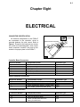
Chapter Eight: Electrical
Connector Identification
Right Side Cover
Left Side Cover
Controller
Quick-Release Connector
Motor
Headlight
Taillight
Troubleshooting
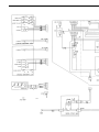
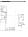
Electrical Schematic
1-1
2-1
3-1
4-1
5-1
6-1
7-1
8-1
1-1
Chapter One
GENERAL
INFORMATION
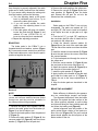
BEEP/LED CODES
The E-Bike™ beeps and flashes various codes to alert the rider to particular conditions. The following chart lists the codes and describes their various functions. Beep codes consist of a series of
long and short beeps, like Morse code. A long beep is represented by a dash (-). A short beep is represented by a dot (•).
Code
OK
GO
Pedal assist
Over heat 1
Over heat 2
System refusal
Battery state of
charge
Low battery
Meaning
The battery pack is
installed and properly
connected.
Sounds at power knob ON.
The system is on and
ready to operate.
The system requests
pedal assist. Sounds
when on a steep hill
or when the motor has
overheated.
The motor is
overheated.
The system will disable the
motor within 3-5
seconds.
Sounds at power knob ON
if the motor has been
disabled.
Beep
--- -•-
--
•
•
--
---
LEDs
The charge level
LEDs cycle twice
in sequence.
•
--- • • • •
Followed by the pedal
assist code (• - - •)
every 8 seconds
--- -
•
-
An error has been
-• --detected. The system
will not operate.
Indicates the battery
state of charge within 3
seconds of power knob ON.
The system will shut
• -• • --down within 3 to 5
seconds.
Green = 100-60%
Yellow = 60-20%
Red = 20-0%
Charge level LEDs
cycle continuously
in sequence.
1-2
VEHICLE IDENTIFICATION NUMBER
This label also contains the gross-vehicle
weight rating and recommended tire inflation
pressure.
The 17-digit vehicle identification number
(VIN) is printed on a label that is affixed to
the inside face of the right frame seat stay.
KEY NUMBER
The 4-digit key number is stamped on the
upper portion of the key shaft.
MODEL CODE
Model code
B1 Bicycles
99-B124BV00-BK,RD
99-B124CV00-BK,RD
99-B124TV00-ML,CR
Model prefix
Year
Description
1B1
2B1
2B1
1999
1999
1999
Base
Comfort
Touring
Color 1
Black (BK)
Black (BK)
Metallic
Blue (ML)
Color 2
Rally Red (RD)
Rally Red (RD)
Metallic
Cranberry (CR)
Color 3
NA
NA
NA
HOW TO READ THE MODEL CODE
Model Year
Product Line
& Category
B1 = Bicycle,
Conventional
Power System
24 = 24 Volts
99 B1 24 C V 00 BK
Model
Brake Type
Battery Type
Base = B
V=V-brake
00=Lead-Acid
Comfort = C D=Disk brake
Touring = T
Color
ML=Metallic Blue
CR = Metallic Cranberry Red
BK = Black
RD = Rally Red
TERMS
Left and Right
NOTE, CAUTION and WARNING
Most of the time, left and right in this manual refer to the rider’s point of view when seated on the E-Bike™ and facing forward. The
one exception to this rule involves the brake
calipers. Left and right on the calipers refers to
a technician’s point of view when standing in
front of the E-Bike™ and looking directly at the
front brake caliper or when standing behind the
E-Bike™ and looking directly at the rear brake
caliper.
The terms NOTE, CAUTION and WARNING have specific meaning in this manual. A
NOTE provides additional information to make
a procedure easier or clearer.
A CAUTION emphasizes precautions that
must be taken to avoid damage to your tools or
to the E-Bike™.
A WARNING alerts you to a situation where
negligence could lead to injury or death. Take
WARNINGS seriously. Failure to heed a
WARNING could result in serious personal
injury or death.
1-3
LUBRICANTS
Grease
The bearings and other mechanical components in the E-Bike™ operate at relatively
low temperatures so most automotive greases
are inappropriate for use on the E-Bike™.
Always use grease made specifically for a
bicycle, such as grease from Bullshot,
Campagnolo, Finish Line, Pedros, Phil Wood,
and Shimano.
promote over-lubrication, which leads to
excessive accumulation of dirt. Apply oil sparingly. Apply enough oil to do the job, but not so
much that it starts to drip from the component.
After applying any oil, wipe off the excess.
THREADLOCK
A threadlocking compound should be used
on most fasteners on the E-Bike™.
Threadlocking compound prevents loosening
caused by vibration and helps seal out moisture.
Loctite 242 (blue) or equivalent is recommended for threadlocking applications. Loctite
242 is a medium-strength threadlocking compound that permits disassembly with common
hand tools.
Before applying Loctite to threads, clean
the thread surface of oil, grease, and other
residue. Apply a small amount of Loctite.
Excess compound could work its way down
the threads and bond parts together. The
torque chart in Chapter Two includes Loctite
recommendations for particular fasteners.
Oil
Always use oils made specifically for bicycle use. Bicycle oils need to be thin enough to
penetrate tight places, they should be durable
so they can withstand exposure to the elements, and they must resist the accumulation
of dirt.
Suitable oils for the E-bike include Alsop,
Bullshot, Campagnolo, Finish Line, Lube Wax,
Phil Wood Tenacous Oil, Pedros, Superlube,
and Triflow.
Motor oil, WD40, 3-in-1 Oil, sewing
machine oil, gun oil, and other common oils
are not suitable and should not be used.
In general, applying oil from a drip applicaRECOMMENDED MAINTENANCE SCHEDULE
Component or Condition
Brake pad adjustment
Wheel quick release adjustment
Tire pressure
Tire wear/damage
Head/tail/brake light operation
Mirror position
Controls and display
Seat post quick release adjustment
Brake pad wear
Brake cable tension/wear
Spoke tension
Wheel true
Hub bearings adjustment
Hub bearing lubrication
Chain lubrication
Derailleur adjustment
Reflectors
Battery and charger
Headset adjustment
Bottom bracket adjustment
Tighten all bolts, nuts, and mounting
hardware
Inspect before every ride
Inspect every 5 to 10 rides*
X
X
X
X
X
X
X
X
X
X
X
X
X
X
X
X
X
X
X
X
X
X
* Depending upon length of ride and riding conditions. Inspect more frequently when riding in dusty or wet
conditions.
1-4
SPECIAL TOOLS
The following special tools are needed for servicing the E-Bike™.
Tool
Hex wrench set: 4mm, 5mm, 6mm
Hex wrench set
Hex wrench set: 2mm, 5mm, 3mm
Fourth hand cable stretcher
Chain checker
Chain breaker (screw type)
Crank wrench
Cable and housing cutter
Gearclean brush
32mm & 36mm head wrench
Pedal wrench
Spoke wrench (black)
Spoke wrench (red)
Tire lever set
Freewheel tool
Bottom-bracket-cartridge tool
Part number
Park AWS-1
Park AWS-11C
Park AWS-3
Park BT-2
Park CC-2C
Park CT-3
Park CCW-14R
Park CN-4C
Park GSC-1
Park HCW-15
Park PW-3
Park SW-0
Park SW-2
Park TL-1C
Park Tool FR-1
Park Tool BBT-2
2-1
Chapter Two
SPECIFICATIONS
Table 1: Mechanical Specifications
Component
Headset
Stack height
Dimensions
Fork
Type
Steerer tube
Travel
Stem 1
Std. model
C & T models
Stem 2
Handlebar
Std model
Rise
Width
Handle
Seat post
Std model
Seat post spacer
Seat post, suspension
C & T models
Seat post spacer
Tires
Std & C models
T model
Rims
Spokes
Front
Rear
Bottom bracket (B/B)
Freewheel
Chainring
Chainring clearance
Crankarm
Chain
Specification
33 mm (1.30 in.)
25.4 mm x 34 mm x 30 mm w/seal
PU Allen key adjustable
1-1/8 in.
65 mm
17 degrees, 110 mm extension
40 degrees, 110 mm extension
28.6 mm x 25.4 mm x 150 mm with quill
30 mm, 10 degrees
620 mm
200 mm
300 mm x 30.0 mm O.D.
100 mm x 30.1 mm ID x 34.9 mm O.D.
350 mm x 27.2 mm O.D.
100 mm x 27.3 I.D. x 34.9 mm O.D.
26 x 1.95 in., black
26 x 1.95 in., Skinwall black
26 x 1.5 in., 14G x 36H, double wall
266 mm, 14G stainless with brass nipples
216 mm & 219 mm, 14G stainless with brass nipples
127 mm cartridge
14-28 T, 7-speed
33 T
16~17 mm (0.63~0.67 in.)
170 mm (6.7 in.)
1/2 x 3/32 x 110 L
Chapter Two
2-2
Table 2: Gear Ratios
Chainring
Freewheel
33T
33T
33T
33T
33T
33T
33T
14T
16T
18T
20T
22T
24T
28T
Gear Inches
61.3
53.6
47.7
42.9
39.0
35.8
30.6
Ratio
0.42
0.48
0.55
0.61
0.67
0.73
0.85
(14/33)
(16/33)
(18/33)
(20/33)
(22/33)
(24/33)
(28/33)
Table 3: Electrical Specifications
Component
Battery (WP12-12)
Type
Capacity
Charger
Input
Output
Charger cord
Length
Wire
Specification
2 in series
Deep discharge, sealed AGM lead-acid
12 volts, 12 amp hours.
115 VAC, 60/50 Hz, 2 amps
24 VDC, 3 amps
1.2 m (4 ft.)
18 AWG, 2-wire with ground
SPECIFICATIONS
2-3
Table 4: Torque Specifications
Item
Handlebar-binder bolt
Handlebar-arm clamp bolts
Stem-binder bolt (stem-2 quill bolt)
Headset locknut
Accessory control clamp bolt
Throttle-control clamp bolt
Controller mounting screw
Brake-lever clamp bolt
Brake-caliper pinch bolt
Brake-pad nut
Caliper pivot bolt
Left-side-cover mounting screws
Right-side-cover mounting screws
Battery-terminal-block mounting screw
Battery compartment mounting screw
Battery pack handle
Battery cover screw
Charger-board mounting screw
Derailleur mounting bolt
Derailleur pinch-mechanism nut
Shifter clamp bolt
Mirror-mounting screw
Chain guard screws
Left bottom-bracket cover screws
Crank-arm mounting bolt
kg-cm
140~200
140~200
180~250
40~50
30~40
30~40
15
30~40
140~200
63.6~85.2
85.2~106.8
10
10
10
10
15
20~30
10
84
42
30~40
30~40
15
20~30
200~250
Pedal
30~50
Bottom-bracket cartridge adapter ring
Chainring bolt
Motor torque arm
Headlight mount
Taillight mounting nut
Horn mounting nut
Cord access cover
Frame mounted connector
Front fender
Rear fender
300~400
350~450
15
15
20
15
5
10
15
15
in.-lb.
34.7~43.4
26.5~34.7
26.5~34.7
13.0
26.5~34.7
53~71
71~89
8.6
8.6
8.3
8.3
13.0
17.4~26.5
8.6
70
36.5
26.5~34.7
26.5~34.7
13.0
17.4~26.5
-
ft.-lb.
10~15
10~15
13~18
10~15
-
*200-pound rider with tires inflated to 60 psi.
Apply Loctite
Apply Loctite
Apply Loctite
Apply Loctite
Apply Loctite
14.4~18.1
Apply Loctite
Apply Loctite
Apply grease to the bolt
threads
26.5~43.4
Apply grease to the stud
threads
21.7~28.9 Apply grease to the threads
25~32
Apply oil to the bolt threads
13.0
Apply Loctite
13.0
17.4
13.0
4.2
8.6
Apply Loctite
13.0
13.0
-
Table 5: Performance Specifications*
Item
Top speed
Range (E mode, flat, no wind)
Maximum gradeability
Acceleration
Special Instructions
Apply Loctite
Apply Loctite
Specification
13.5-14.0 mph
18-20 miles
11% grade, 6 mph
0-10 mph in 5.3 seconds
2-4
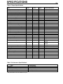
Frame Specifications
Head Tube
163 mm (6.4 in.)
Frame Size (Center to top)
419 cm (16.5 in.)
72˚
RC 431.5 mm
(17.0 in.)
Wheel Base 1062.3 mm (41.8 in.)
3-1
Chapter Three
BATTERY PACK
CHARGING THE BATTERIES
The E-Bike™ includes a charger that is an
integral part of the battery pack. Batteries can
be charged when the battery pack is on-board
the E-bike™ or when the battery pack is
removed for remote charging.
To assure maximum battery life, always
fully recharge the battery after each ride. If the
E-Bike™ will not be used for more than one
week, remove the battery pack from the EBike™ and store it in a cool, dry place. The
controller uses a small amount of power whenever the battery pack is installed in the EBike™. Consequently, the batteries slowly discharge whenever the battery pack is in place,
even if the power knob is OFF. To prevent total
battery discharge during extended periods of
non-use, remove the battery pack and store it
in a cool, dry place. A stored battery should be
recharged at least every three months to help
maintain performance and quality.
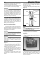
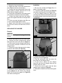
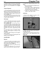
On-board Charging
1. Be sure the power knob is turned OFF.
2. Turn the battery-compartment latches
clockwise, and open the door.
3. Retrieve the charging cord from the compartment above the bottom bracket.
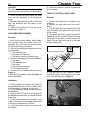
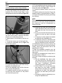
4. Plug the female end of the charging cord
into the receptacle on the battery
charger.(Figure 1)
FIG.1
WARNING
The charger is equipped with a cooling fan. If
the cooling fan does not operate when the
charging cord is plugged in and the red LED is
on, unplug the charger from the electrical outlet immediately. Determine why the fan is not
operating before charging the battery pack.
Replace the charger if necessary.
5. Plug the male end of the charging cord into
a standard 110V/60 cycle electrical outlet. The
red LED on the charger and the cooling fan will
automatically turn on. The LED switches to
green and the cooling fan turns off when the
battery pack is fully charged.
Remote Charging
1. Remove the battery pack from the E-Bike™.
2. Set the battery pack on its side so the battery-pack cover faces up and the handle is to
the side.
Chapter Three
3-2
3. Retrieve the charging cord from the compartment above the bottom bracket.
4. Plug the female end of the charging cord
into the receptacle on the battery charger.
WARNING
The charger is equipped with a cooling fan. If
the cooling fan does not operate when the
charging cord is plugged in and the red LED is
on, unplug the charger from the electrical outlet immediately. Determine why the fan is not
operating before charging the battery pack.
Replace the charger if necessary.
5. Invert the battery case. Tap the case against
the bench or floor to dislodge the batteries
from the battery pack.
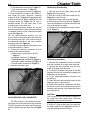
6. Remove each battery and its damper strap
(Figure 3).
Black
Bullet Connector
Interconnect Wire
(Blue)
Bullet Connector
Fuse
5. Plug the male end of the charging cord into
a standard 110V/60 cycle electrical outlet. The
red LED on the charger and the cooling fan will
automatically turn on. The LED switches to
green and the cooling fan turns off when the
battery pack is fully charged.
Red
Black
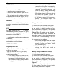
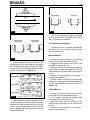
REPLACING THE BATTERIES
The battery pack contains two sealed leadacid batteries that are connected in series. The
following procedure describes how to remove
and replace the two batteries.
CAUTION
Always replace both batteries as a set. Do not
mix old batteries with new batteries, and do not
mix different brands of batteries.
WARNING
Never use a battery that is cracked or broken.
Battery acid is highly corrosive and can cause
severe burns if it comes in contact with your
eyes or skin.
FIG. 2
NOTE
Contact your state or local agency for information on proper battery disposal.
7. Properly dispose of the old batteries.
Installation
1. Wrap the damper strap around the first battery (Figure 3).
Removal
1. Remove the battery pack from the E-Bike™.
2. Remove the two cover screws from the battery pack, and remove the cover.
3. Disconnect and remove the blue interconnect wire that connects the two batteries to
each other in series. Note the fuse on the interconnect cable (Figure 2).
4. Disconnect the battery-pack leads (black
and red) from the spade connectors on each
battery.
FIG.3
2. Set the battery into the compartment so the
end with the spade connectors faces the
charger. Press the battery into the compartment until it bottoms.
3-3
3. Repeat for the second battery.
4. Inspect the fuse on the blue interconnect
wire. Replace the fuse as necessary.
5. Connect the blue interconnect wire to the
upper battery’s positive terminal and to the
lower battery’s negative terminal.
6. Connect the red lead from the battery pack
to the positive terminal on the lower battery.
7. Connect the black lead from the battery
pack to the negative terminal on the upper battery.
8. Fit the cover onto the battery pack. Be sure
no wire is pinched beneath the cover.
9. Apply Loctite 242 (blue) to the threads of
the two cover screws, and secure the cover in
place.
Installation
1. Be sure the insulator (B, Figure 6) is in
place in the battery pack.
2. If removed, install the spacer (A, Figure 6)
onto each mounting stud in the battery pack.
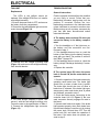
3. Set the charger board into place on the
mounting studs. Secure the board in place with
the charger-board mounting screws and washer (Figure 5).
REPLACING THE CHARGER
Removal
WARNING
Make sure the charger is not plugged in during
service.
FIG. 5
A
A
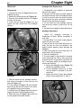
1. Remove the batteries from the battery pack.
2. Remove the three charger-cover screws
that secure the cover to the vent (A, Figure 4).
3. Lift the cover from the charger, and disconnect the three electrical connectors from the
charger board.
4. Remove the screw that secures the charger board to the bracket (B, Figure 4).
B
A
A
B
FIG. 6
A
A
FIG.4
5. Remove the three charger-board mounting
screws (Figure 5), and remove the charger
board. Do not lose the spacer (A, Figure 6)
from each mounting stud.
4. Secure the board to the bracket with the
mounting screw (B, Figure 4).
5. Plug the connectors from the cover into
their mates in the charger board.
6. Fit the cover in place over the charger
board. Be sure the two charger wires are not
pinched under the cover.
7. Secure the cover in place with the three
charger-cover screws (A, Figure 4).
8. Reinstall the batteries and the battery-pack
cover.
3-4
BATTERY PACK
Removal
1. Turn the power knob OFF.
2. Open the battery compartment door.
3. Release the gate latch, and open the battery gate.
4. Use the handle to pull the battery pack from
the compartment. Be sure to support the bottom of the battery pack with your free hand.
Installation
1. Set the lower end of the battery pack into
the battery compartment, and tilt the battery
into place.
NOTE
The E-Bike™ beeps the OK (_ _ _ _•_) whenever the battery pack is reinstalled and good
contact exists between the battery pack and
terminal block in the E-Bike™.
2. Close the gate over the battery, and secure
the gate latch.
3. Close the battery compartment door, and
turn the latches counterclockwise.
BATTERY PACK TEST
Charger operation test
1. Plug the female end of the charging cord into
the port on the charger.
2. Plug the male end into a 110-volt outlet.
3. Watch the battery charger LED and perform
the indicated procedure.
a. If the battery charger LED does not illuminate, the charger is faulty and should
be replaced. Unplug the charging cord,
and check the battery voltage (before
charging) as described below.
b. If the battery charger LED turns to
red and the cooling fan is not operating,
the charger is faulty and should be
replaced. Unplug the charger, and
check the battery voltage (before charg
ing) as described below.
c. If the battery charger LED turns red and
the cooling fan operates, perform the
charger output test described below.
d. If the battery charger LED turns green,
perform the charger output test
described below.
Charger Output Test
1. Remove the cover from the battery pack.
2. Connect a voltmeter’s positive (+) test probe
to the positive (+) battery terminal, and connect the voltmeter’s negative (-) test probe to
the battery negative terminal as shown in
Figure 7. Note the reading on the voltmeter.
3. With the voltmeter still connected as
described in step 2, plug the charger into a
110-volt outlet. Note the reading on the voltmeter.
4. Compare the two readings.
a. If the reading is higher when the charger
is plugged in, the charger is operating
properly. Perform the battery voltage
test (before charging).
b. If the two readings are the same, the
charger has failed and should be
replaced.
Battery Voltage Test, Before Charging
1. Let the battery stand for one hour.
2. Remove the cover from the battery pack.
3. Connect a voltmeter’s positive (+) test probe
to the positive (+) battery terminal, and connect the voltmeter’s negative (-) test probe to
the battery negative terminal as shown in
Figure 7.
4. Note the reading on the voltmeter.
5. If the reading is less than 12 volts, the battery is faulty and should be replaced.
3-5
Battery Voltage Test, After Charging
NOTE
The charger must be operational for this test to
be valid. Perform the charger output test before
performing this test.
1. Charge the battery as described in this
chapter.
2. Unplug the charger, and let the battery
stand for one hour.
3. Remove the cover from the battery pack.
4. Connect a voltmeter’s positive (+) test
probe to the positive (+) battery terminal, and
connect the voltmeter’s negative (-) test probe
to the battery negative terminal as shown in
Figure 7.
5. Note the reading on the voltmeter.
6. The reading should be 12.5 volts or greater.
If the reading is less than 12.5 volts, the battery is faulty and should be replaced.
FIG. 7
4-1
Chapter Four
HANDLEBAR
and CONTROLS
HANDLEBAR HEIGHT ADJUSTMENT
HANDLEBAR POSITION
NOTE
The handlebar may be adjusted to suit the
rider’s preference. The following procedure
describes how to set the handlebar to the stock
position.
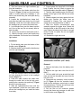
1. Loosen the stem-binder bolt three or four
turns counterclockwise (A, Figure 3). If the bolt
rises from the steering stem, strike the bolt with
a plastic mallet to force the stem wedge down.
1. Loosen the handlebar-binder bolts (A,
Figure 1).
A
B
10~20˚
A
FIG. 2
C
FIG.1
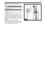
2. Position the handlebar so the ends point
down slightly. The handlebar grips should form
a 10-20˚ angle with a line that parallels the
floor. See Figure 2.
3. Be sure the knurled portion of the handlebar
is centered within the handlebar binder.
4. Tighten the handlebar-binder bolts to the
torque specification in Table 4.
B
B
FIG. 3
A
Chapter Four
4-2
CAUTION
The "Minimum Insert" mark on the handlebar
stem must not sit above the top of the headset.
6. Install the accessory control as described
in this chapter.
THROTTLE CONTROL (RIGHT SIDE)
2. Raise or lower the stem within the head
tube until the handlebar is at the desired
height.
3. Rotate the handlebar from side to side, and
align the handlebar with the wheel or fork
dropouts.
4. Tighten the stem-binder bolt to the torque
specification in Table 4.
HANDLEBAR REPLACEMENT
Removal
1. Note how the brake cables, shifter cable,
and electrical wires are routed around the
headlight. They will have to be rerouted along
the same path during installation.
2. Remove the following components from the
right handlebar:
a. The handlebar grip.
b. The brake-lever housing
c. The throttle control and throttle stop.
3. Remove the following from the left handlebar:
a. The mirror.
b. The handlebar grip
c. The shifter.
d. The brake-lever housing.
e. The accessory control.
4. Remove the two handlebar-binder bolts (A,
Figure 1).
5. Remove the handlebar clamp (B, Figure 1)
and the handlebar.
Removal
1. Remove the battery from the battery compartment.
2. Remove the right side cover from the EBike™.
3. Pull the cable inlet cover around the head
tube, and remove the cable inlet cover from the
left side cover.
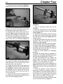
4. Disconnect the throttle control connector (F,
Figure 4) from the controller board. Note how
the throttle control wire is routed through the
frame. The new wire will have to be rerouted
along the same path.
Yellow N
L
Behind
Behindcontroller
controllerconnectors
connectors
A
B
K G
J
H
I
Black
Red
C
D
E
Controller board
F
FIG. 4
5. Pull the wire so the connector passes
through the frame and emerges at the cable
inlet in the left side cover (Figure 5).
Installation
1. Fit the handlebar into place in the binder on
the handlebar arm. Be sure the knurled portion
of the handlebar is centered in the binder.
2. Fit the handlebar clamp into place around
the handlebar.
3. Apply Loctite 242 (blue) to the threads of
the handlebar-binder bolts, and install the bolts
finger tight.
4. Position the handlebar as described in this
chapter, and tighten the handlebar-binder bolts
to the torque specification in Table 4.
5. Install the throttle control as described in
this chapter.
Horn board
board
Horn
M
FIG. 5
HANDLEBAR and CONTROLS
6. Twist and remove the right handlebar grip
from the handlebar.
7. Disconnect the front brake cable from the
S-hook (C, Figure 1). Note how the front brake
cable is routed around the headlight. It will
have to be routed along the same path during
assembly.
8. Loosen the right-brake-lever clamp bolt,
and slide the brake lever body from the right
handlebar. Guide the front brake cable around
the headlight as you remove the brake lever.
9. Lay the brake lever over the frame top tube
so it is out of the way. Do not severely bend or
kink the cable.
10. Loosen the set bolt on the throttle control.
11. Slide the throttle control and throttle stop
off the handlebar. Pull its wire free of the headlight bracket.
4-3
6. Finger tighten the clamp bolt to hold brake
body in place. Use the S-hook to secure the
front brake cable to the shifter cable (C, Figure 1).
7. Twist the right handlebar grip onto the handlebar until the grip is flush with the end of the
handlebar.
8. Slide the brake lever body against the handlebar grip. Position the brake lever as
described in Chapter Five, and torque the
clamp bolt to the specification in Table 4.
9. Slide the throttle control/throttle stop
assembly against the brake lever. Rotate the
throttle control so the LEDs point to the rider’s
eyes.Tighten the clamp bolt so there is enough
friction to hold it in place. Do not over tighten
the clamp bolt.
10. Reinstall the right side cover.
Installation
1. Fit the throttle stop onto the bottom of the
throttle control (Figure 6).
2. Slide the throttle control and the throttle stop
onto the right handlebar.
FIG. 7
ACCESSORY CONTROL (LEFT SIDE)
Removal
FIG. 6
3. Feed the connector end of the throttle control wire through the cutout in the headlight
bracket (Figure 7).
4. Feed the cable around the head tube,
through the cable inlet in the left side cover,
and plug the connector into position (F, Figure
4) on the controller panel.
5. Slide the right-brake-lever body onto the
right handlebar. Guide the front brake cable
around the headlight as you install the brake
lever body.
1. Remove the battery from the battery compartment.
2. Remove the right side cover from the EBike™.
3. Pull the cable inlet cover around the head
tube, and remove the cable inlet cover from the
left side cover.
4. Disconnect the accessory control connector (E, Figure 4) from the controller board.
Note how the accessory control wire is routed
through the frame. The new wire will have to be
rerouted along the same path.
5. Pull the wire so the connector passes
through the frame and emerges at cable inlet
in the left side cover (Figure 5).
Chapter Four
4-4
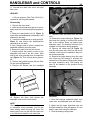
6. Loosen the mirror-mounting bolt (Figure 8),
and remove the mirror from the handlebar end.
FIG.10
FIG. 8
7. Twist the left handlebar grip from the handlebar. Do not lose the shim that sits between
the handlebar grip and the shifter body.
8. Disconnect the shifter cable from the Shook (C, Figure 1). Note how the cable is routed around the headlight. It will have to be routed along the same path during assembly.
9. Loosen the shifter clamp bolt, and slide the
shifter body from the handlebar (Figure 9).
FIG. 9
Guide the shifter cable around the headlight as
you remove the shifter. Lay the shifter over the
frame top tube so it is out of the way. Do not
severely bend or kink the cable.
10. Loosen the clamp bolt on the brake-lever
body (Figure 10), and remove the body from
the handlebar. Guide the brake cable around
the headlight as your remove the lever body.
Lay the lever body over the frame top tube so
it is out of the way.
11. Loosen the set bolt on the accessory control. Slide the housing off the handlebar. Pull its
wire free of the headlight bracket.
Installation
1. Slide the accessory control onto the left
handlebar.
2. Feed the connector end of the accessory
control wire through the cutout in the headlight
bracket (Figure 7).
3. Feed the wire around the head tube, through
the cable inlet in the left side cover, and plug
the connector into position (E, Figure 4) on the
controller panel.
4. Slide the rear-brake-lever body onto the left
handlebar. Take care to guide the rear brake
cable around the headlight.
5. Slide the shifter body onto the left handlebar.
Guide the shifter cable around the headlight.
6. Slide the shim onto the handlebar. Twist the
handlebar grip onto the handlebar until the grip
is flush with the handlebar end.
7. Slide the shifter against the handlebar
grip/shim.
8. Position the shifter body as described in
Chapter Six, and tighten the shifter-body clamp
bolt to the torque specification in Table 4.
9. Slide the brake-lever body against the
shifter. Position the brake lever as described in
Chapter Five, and torque the brake-lever
clamp bolt to the specification in Table 4.
10.Fit the mirror mount into the handlebar end
(Figure 8). Position the mirror, and tighten the
mirror mounting bolt to the torque specification
in Table 4.
11. Slide the accessory control against the
brake lever. Rotate the accessory control on
the handlebar to the same relative position as
the throttle control housing. Tighten the clamp
bolt so there is enough friction to hold it in
place. Do not over tighten the clamp bolt.
12. Use the S-hook to secure the shifter cable
to the front brake cable (C, Figure 1).
HANDLEBAR and CONTROLS
4-5
13. Reinstall the cable inlet cover and right
side cover.
HEADSET
A 36-mm spanner (Park Tool HCW-15) is
required for servicing the headset.
Disassembly
1. Remove the front wheel.
2. Mark the stem height with tape so it can be
easily reset to the correct height during assembly.
3. Break the stem-binder bolt (A, Figure 3)
loose while the handlebar/arm assembly is still
attached to the stem.
4. Loosen the handlebar-arm clamp bolts (B,
Figure 3), and remove the handlebar/arm
assembly from the stem.
5. Use a bungee cord or wire to suspend the
handlebar assembly from the frame.
6. Remove the stem from the fork column.
7. Visually inspect the position of cone in the
adjustable race and in the fork crown. Note
how far the cone protrudes from its respective
cup (Figure 11). This will help during assembly.
8. Remove the headset locknut with the Park
36 mm wrench (Figure 12).
9. Remove the washer and the headlight
FIG. 12
11. Carefully lower the forks from the head
tube.
12. Remove the lower bearing (A, Figure 13).
Note how the bearing is oriented (the closed
side of the retainer facing up toward lower
head-tube race). The bearing will have to be
installed in this position during assembly.
13. Remove the rubber seal (B, Figure 13)
from the fork-crown race. Note how the seal is
oriented. It will have to be installed in this position during assembly.
14. Remove the upper bearing from the head
tube. Note how the bearing is oriented (the
closed side of the retainer facing down toward
the upper head-tube race). The bearing will
have to be installed in this position during
assembly.
A
B
FIG. 11
bracket from the fork column.
10. Support the forks, and remove the
adjustable race from the fork column.
NOTE
The bearing must be reinstalled with the proper orientation during assembly. Look for the
lower bearing when removing the forks. The
bearing may come out with the fork-crown race
or it could remain behind in the head tube.
FIG. 13
Assembly
1. Clean the bearings, head-tube races, forkcrown race, and adjustable race with solvent.
2. Lightly coat the upper head-tube race and
the lower head-tube race with grease. A 1-mm
bead in each race should be sufficient.
3. Pack the bearings with grease.
4-6
NOTE
The grease in the lower head-tube race should
hold the bearing in place during assembly.
4. Press each bearing into the grease in the
head-tube. Be sure the closed side of each
bearing faces the race in the head tube (Figure 14).
12. Fit the headlight bracket and washer on the
fork column. Be sure their notches engage the
slot in the column (B, Figure 15).
13. Thread the headset locknut onto the fork
column.
14. Install the wheel onto the forks. Torque the
headset locknut to the specification in Table 4.
15. Check the headset free play by performing
the following.
NOTE
Do not check for headset free play by grasping
the bottom of the forks. Normal movement in
the suspension could be misinterpreted as
bearing free play.
FIG. 14
5. Set the seal in place on the fork-crown
race. Be sure the seal is oriented in the same
direction you noted during removal.
6. Apply grease to the threads of the fork column.
7. Fit the fork column up into the head tube.
8. Thread the adjustable race (A, Figure 15)
onto the fork column.
A
B
FIG. 15
9. Let the forks drop down so the forks are supported by the adjustable race.
10.Turn the adjustable race until the forks are
drawn up into the head tube.
11. Inspect the position of each cone relative to
its race. Each cone should be in the position
you noted during removal.
a. Grasp the fork crown with one hand (the
upper stanchions above the fork boots)
and grasp the lower fork tube with the
other.
b. Try to move the forks back and forth. You
should not notice any play in the head
set.
c. If free play is noticed, adjust the headset
by tightening the adjustable race.
d. If looseness cannot be eliminated with
out the bearings becoming excessively
tight, the headset must be overhauled.
16. Reinstall the stem into the fork column. Set
the stem to the height you noted during disassembly. Torque the stem-binder bolt to the
specification in Table 4.
17.Slide the handlebar assembly onto the
stem. Be sure the top of the arm is below the
stem crown.
18.Tighten the handlebar-arm clamp bolts to
the specification in Table 4
19. Check for tight bearings by performing the
following.
a. Turn the handlebars from side to side.
The forks should turn smoothly with no
binding. The bearings are too tight if you
feel jerky, incremental movement
instead of a smooth, fluid motion.
b. Lift the E-Bike™ by the top frame tube,
and watch the front wheel. It should
freely rotate to one side or the other. The
bearings are too tight if the wheel does
not fall to one side when you lift the EBike™.
c. If necessary, adjust the headset by loosening the adjustable race.
5-1
Chapter Five
BRAKES
V-BRAKES
NOTE
When working on the brake calipers and pads,
the terms "left" and "right" refer to the technician’s point of view when standing in front of
the E-Bike™ and looking at the front brake
caliper or when standing behind the E-Bike™
and looking at the rear brake caliper.
5. Pull the cable housing from the adjusting
barrel, and slide the inner cable through the
slots in the brake lever, adjusting barrel, and
adjuster locknut (Figure 2).
BRAKE CABLE REPLACEMENT
Removal
1. Squeeze the caliper arms together, and disconnect the cable guide from the bracket on
the left caliper arm (A, Figure 1).
FIG. 2
B
6. Pull the brake lever toward the handlebar,
and disconnect the inner-cable barrel (Figure
3) from the cable anchor on the lever.
A
FIG. 1
2. Loosen the caliper pinch bolt (B, Figure 1),
and free the brake-cable inner wire from the
pinch mechanism.
3. Loosen the adjuster locknut at the brake
lever.
4. Turn the barrel adjuster and the adjuster
locknut until their slots align with the slot in the
brake lever body.
FIG. 3
NOTE
If the cable housing is not damaged, the rearbrake inner wire can be removed and
replaced without removing the cable housing
or the left side cover.
Chapter Five
5-2
7. Remove the brake cable. If you are replacing the rear brake cable, remove the left side
cover, and remove the cable from the rear inlet
on the side cover.
Installation
1. At the brake lever, align the slots in the
brake lever, barrel adjuster, and the barrel locknut.
2. Pull the brake lever to the handlebar, and fit
the inner cable barrel into the cable anchor in
the brake lever (Figure 3).
3. Slide the inner cable through the slots in
the brake lever, barrel adjuster, and the barrel
locknut (Figure 2).
4. Turn the barrel adjuster three full turns out
from its fully-in position.
Turn the barrel adjuster and locknut so their
slots do not align with the slot in the brake
lever.
5. If necessary, align the brake pads as
described in this chapter.
6. Route the cable to the caliper. If you are
replacing a rear brake cable, route the cable
through the rear cable inlet in the left side
cover.
7. Fit the cable guide into the bracket on the
left caliper arm (A, Figure 1).
8. Squeeze the caliper arms together, and
connect the cable guide to the bracket on the
left caliper arm.
9. Secure the inner wire in the brake-caliper
pinch mechanism by performing the following:
a. Feed the brake cable inner wire through
the slot in the pinch mechanism.
b. Use the fourth-hand cable stretcher
(Park Tool BT-2) to pull the inner wire
until the combined clearance between
each brake pad and the rim equals
2 mm (0.08 in.).
c. Tighten the pinch bolt (B, Figure 1) to the
specification in Table 4.
d. Crimp a new end cap onto the end of the
inner wire.
10. Depress and release the brake lever several times, and check the caliper arm balance.
a. The brake pads should contact the rim at
the same time when the brakes are
applied.
b. The gap between each pad and the rim
should equal 1 mm (0.04 in.) when the
brake lever is released.
CAUTION
Do not set the caliper-arm spring tension too
high.
c. If necessary, balance the caliper arms by
turning the spring-tension adjuster (B,
Figure 4) on either arm.
B
A
FIG.4
11. Adjust the brake lever free play as
described in this chapter.
BRAKE LEVER
Removal
1. Remove the handlebar grip from the handlebar.
2. If removing the left brake lever, perform the
following:
a. Loosen the mounting screw, and remove
the mirror from the left-end of the handlebar (Figure 5).
FIG. 5
b. Loosen the set screw on the shifter, and
remove the shifter from the handlebar.
Lay the shifter over the handlebar so it is
out of the way.
BRAKES
3. Squeeze the caliper arms together, and disconnect the cable guide from the bracket on
the left caliper arm (A, Figure 1).
4. Loosen the adjuster locknut at the brake
lever.
5. Turn the barrel adjuster and the adjuster
locknut until their slots align with the slot in the
brake lever body.
6. Pull the inner cable from the adjusting barrel, and slide the inner cable through the slots
in the brake lever, adjusting barrel, and
adjuster locknut (Figure 2).
7. Disconnect the cable end from the cable
anchor in the brake lever (Figure 3).
8. Loosen the brake-lever clamp bolt (Figure
6), and slide the brake lever body from the handlebar.
5-3
the handlebar grip so it is flush with the handlebar end.
7B. When installing the left brake lever, install
the shifter onto the handlebar as described in
Chapter Six.
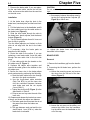
8. Set the brake lever to a 25~35° angle by performing the following:
a. Set the E-Bike™ in an upright position on
a
level surface.
b. Slide the brake-lever body against the
shifter (left brake lever) or against the
handlebar grip (right brake lever).
c. Rotate the brake lever so it is forms a
25~35° angle with a line that parallels
the floor (Figure 7).
d. Tighten the brake lever clamp bolt to the
torque specification in Table 4.
25 - 35˚
FIG.6
Installation
1. Fit a new brake-lever body onto the handlebar, and slide the brake-lever body against the
throttle control.
2. Turn the barrel adjuster and the adjuster
locknut until their slots align with the slot in the
brake lever body.
3. Connect the end of the brake-cable inner
wire to cable anchor in the brake lever (Figure
3).
4. Slide the inner cable through the slots in
the brake lever, adjuster barrel and adjuster
locknut (Figure 2). Fit the cable into barrel
adjuster.
5. Turn the barrel adjuster and adjuster locknut so their slots do not align with the slot in the
brake lever.
6. Squeeze the caliper arms together, and fit
the cable guide into the bracket on the left
caliper arm (A, Figure 1). Be sure the guide
end is completely seated in the bracket.
7A. When installing the right brake lever, install
FIG.7
9. Adjust the brake lever free play as
described in this chapter.
BRAKE LEVER FREE PLAY ADJUSTMENT
1. Pull the brake lever to simulate a panic
stop, and then release the brake lever. Repeat
this at least ten times. This assures that all
components are properly installed and seated.
2. Pull the brake lever until the brake pads just
touch the rim.
3. Measure the clearance between the brake
lever and the handlebar grip. This distance
should be 25 mm (0.98 in.).
4. Turn the barrel adjuster as necessary to
adjust clearance to within specification.
(Turning the adjuster out tightens the inner
wire; turning the adjuster in loosens the wire.)
When the brake lever is within specification,
tighten the adjuster locknut.
5. Squeeze the caliper arms together, and
remove the cable guide from the bracket on the
left caliper arm (A, Figure 1). The brake-
Chapter Five
5-4
lever free play is properly adjusted if the cable
guide can be easily removed from the bracket.
6. If you cannot easily release the cable guide
from the bracket, perform the following:
a. Turn the adjusting barrel at the brake
lever in (clockwise) one full turn. Try to
remove the cable guide again.
b. If you still cannot release the cable
guide, turn the adjusting barrel in an
additional turn.
c. If the cable guide still does not release,
loosen the pinch bolt (B, Figure 1) and
release 2-3 mm (0.079-0.118 in.) of
inner wire from the pinch mechanism.
d. Repeat the adjusting procedure.
BRAKE PAD
The brake pads in the E-Bike™ use a
threaded-stud/curved-washer system (Figure
8). Convex and concave washers on each side
of the brake caliper arm control how the pad is
positioned against the wheel.
A
B
C
D
E
F
FIG.8
Removal
NOTE
Do not mix the parts during disassembly. The
convex and concave washers become mated
through use, and they must be reinstalled in
the same position during assembly.
1. Squeeze the caliper arms together, and disconnect the cable guide from the bracket (A.
Figure 1) on the left caliper arm.
2. Remove the brake pad nut from the pad stud
(F, Figure 8).
3. Remove the plain washer (E, Figure 8), the
concave washer (D, Figure 8), and the convex
washer (C, Figure 8) from the pad stud.
4. Remove the brake pad from the caliper arm.
5. Remove the convex (B, Figure 8) and concave washers (A, Figure 8) from the brake
pad. Discard the old pad. Do not mix the
inboard and the outboard parts.
Installation
Brake pads on the E-Bike™ are not interchangeable. The pads are marked left ("L")
and right ("R"). Be sure to install a left pad on
a left caliper arm and a right pad on a right
arm.
1. Find the left ("L") or right ("R") marking on
the new brake pad. Be sure to install the correct pad onto the caliper arm.
2. Install the inboard concave washer (A,
Figure 8) onto the stud of the new brake pad.
The flat side of the washer must face the brake
pad.
3. Install the inboard convex washer (B, Figure
8) onto the pad stud so the convex side faces
the concave washer.
4. Fit the brake-pad stud through the cutout in
the caliper arm.
5. Slide the convex washer (C, Figure 8) onto
the pad stud so the convex side faces out.
6. Install the concave washer (D, Figure 8) so
the flat side of the washer faces out.
7. Install the plain washer (E, Figure 8).
8. Apply Loctite to the threads of the pad stud,
and install the brake pad nut (F, Figure 8).
Tighten the nut to the torque specification in
Table 4.
9. Align the brake pads as described in this
chapter.
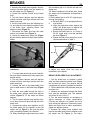
BRAKE PAD ALIGNMENT
Brake efficiency is affected by four parameters: toe, vertical-angle, tangent, and height.
Toe alignment determines how the brakepad face sits against the brake surface of the
rim. When properly adjusted, a pad’s trailing
end (the end facing the front) should reach the
rim before the leading end (Figure 9).
Vertical alignment sets the position of the
pad’s vertical plane relative to the brake surface of the rim (Figure 10). The pad’s vertical
plane should parallel the vertical plane of the
brake surface of the rim.
BRAKES
5-5
Goodheight
height
Good
Too
Toohigh
high
Front
Front
FIG. 9
Good vertical
od verticle-angle
alignment
alignment
FIG. 12
vertical
PoorPoor
verticle-angle
alignment
alignment
Toe, vertical alignment, tangent, and height
must be set whenever the brake pads, caliper
arms, or wheels are replaced.
Toe and Vertical Alignment
Toe can be set by manually manipulating
the pad or by using a spacer. Both methods
are described below.
Manual Method
FIG. 10
Tangent alignment sets the position of the
horizontal axis of the pad relative to the wheel
rim. The distance between the top of the wheel
rim and the top of the pad should be the same
at each end of the pad. (Figure 11)
Good tangent
Poor tangent
1. Loosen the pad mounting nut just enough
so the pad can be manipulated by hand.
2. Adjust the brake cable so the face of the
pad almost touches the rim.
3. Manually set the toe by pulling the leading
edge of the pad (rear side) away from the rim
while pressing the trailing edge (front side) to
the rim.
4. Tighten the pad mounting nut enough to
hold the pad in position.
5. Visually inspect the pad for vertical-angle
alignment. If necessary, manipulate the pad so
the pad face parallels the surface of the rim
(Figure 10).
Spacer Method
Poor tangent
FIG. 11
Height adjustment locates the brake pad in
the rim brake surface. When height is properly
adjusted, the pad will press as near to the top
of the rim as possible without interfering with
the tire (Figure 12). Pad alignment procedure
is described below.
1. Loosen the pad mounting nut just enough
so the pad can be manipulated by hand.
2. Put a spacer between the leading edge
(rear edge) of the pad and the rim.
3. Adjust the brake cable so the face of the
trailing edge (front edge) of the pad touches
the rim.
4. Tighten the pad mounting nut enough to
hold the pad in position.
Chapter Five
5-6
5. Visually inspect the pad for vertical-angle
alignment. If necessary, manipulate the pad so
the face of the pad parallels the rim (Figure
10).
Tangent Alignment
1. Look at each pad from the side, and note the
position of the top of the pad relative to the rim.
The distance from the top of the pad to the top
of the rim should be the same at each end of
the pad (Figure 11).
2. If one end of the pad is closer to the rim than
the other, rotate the pad around the shoe stud
to adjust tangent alignment.
4. Inspect the caliper-mounting boss in the
frame.
a. Be sure the threads of the caliper-mounting boss are clean.
b. The mating surface caliper-mounting
boss should also be clean. Dress the
area with emery cloth if necessary.
c. Inspect the caliper-mounting boss for
cracks or other signs of wear.
Installation
1. Check that the washer is in place on the
caliper-arm pivot bolt (Figure 13).
Pad Height
1. Look at each pad from the side, and note
where the pad engages the brake surface of
the rim. (Figure 12).
2. To adjust the height, move the brake stud up
or down in the caliper slot. Adjust height so the
pad presses against the top of the rim without
interfering with the tire. The top of the pad
should be 1 mm (0.04 in.) below the top of the
rim.
3. If pad height cannot be adjusted without
affecting vertical alignment, correctly set the
pad height.
4. Torque the pad mounting nut to the specification in Table 4.
5. If removed, reconnect the cable guide to the
bracket in the left caliper arm.
FIG. 13
2. Apply Loctite 242 (blue) to the threads of
the caliper pivot bolt.
3. Align the pin on the caliper bushing with the
indexing hole in the caliper-mount boss
(Figure 14).
CALIPER ARM
Removal
1. Squeeze the caliper arms together, and disconnect the cable guide from the bracket on
the left caliper arm (A, Figure 1).
2. Loosen and unthread the caliper pivot bolt.
(A, Figure 4)
3. Remove the caliper arm. Do not lose the
washer that sits behind the caliper pivot bolt.
FIG. 14
BRAKES
4. Thread the caliper-pivot bolt into the calipermounting boss. As you tighten the pivot bolt,
be sure the pin engages then indexing hole in
the boss.
5. Torque the caliper pivot bolt to the specification in Table 4.
6. Align the brake pads as described in this
chapter.
7. Squeeze the caliper arms together, and connect the cable guide to the bracket on the left
caliper arm (A, Figure 1).
8. Secure the inner wire in the brake-caliper
pinch mechanism by performing the following:
a. Feed the brake cable inner wire through
the slot in the pinch mechanism.
b. Use the fourth-hand cable stretcher
(Park Tool BT-2) to pull the inner wire
until the combined clearance between
each brake pad and the rim equals 2
mm (0.08 in.).
c. Tighten the pinch bolt (B, Figure 1) to the
specification in Table 4.
d. Crimp a new end cap onto the end of the
inner wire.
9. Depress and release the brake lever several
times, and check the caliper arm balance.
a. The brake pads should contact the rim at
the same time when the brakes are
applied.
b. The gap between each pad and the rim
should equal 1 mm (0.04 in.) when the
brake lever is released.
CAUTION
Do not set the caliper-arm spring tension too
high.
c. If necessary, balance the caliper arms by
turning the spring-tension adjuster (B,
Figure 4) on either arm.
10. Adjust the brake lever free play as
described in this chapter.
5-7
DISC BRAKE
Brake Pad Clearance Adjustment
1. Hold the adjuster (A, Figure 15) with an
Allen wrench, and loosen the adjuster locknut
(B, Figure 15).
B
A
FIG. 15
2. Spin the wheel and turn the adjuster clockwise until the brake pads barely scrape against
the brake disc.
3. Back out the adjuster 1/2 turn (counterclockwise).
4. Hold the adjuster with an Allen wrench, and
tighten the locknut (B, Figure 15) securely.
5. Set the pads by sharply apply the brakes
four or five times.
NOTE:
A slight amount of pad scraping is normal,
especially with new brakes or new brake pads.
6. Spin the wheel and check for brake pad/disc
scraping. Repeat the adjustment procedure if
scraping is noted.
6-1
Chapter Six
SHIFTER and
DERAILLEUR
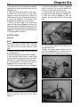
SHIFTER
Removal
1. Remove the shift cable from the S-hook
(Figure 1) that holds the cable to the front
brake cable.
2. Loosen the mounting screw in the mirror
housing, and remove the mirror from the end of
the handlebar Figure 2.
3. Remove the handlebar grip from the left end
of the handlebar. Do not lose the shim between
the grip and the shifter housing.
4. Loosen the shifter clamp bolt, and slide the
shifter housing from the handlebar (Figure 3).
Guide the shifter cable around the headlight as
you remove the shifter housing.
FIG. 1
FIG. 3
5. If you are not servicing the shifter or the
cable, lay the shifter over the top tube. Secure
it in place so it will remain out of the way. Do
not severely bend or kink the cable.
Installation
FIG. 2
1. Slide the shifter housing onto the left end of
the handlebar (Figure 3).
2. Gently route the shifter cable over and
behind the headlight as you slide the shifter
housing against the brake-lever body.
Chapter Six
6-2
3. Slide the shim onto the handlebar. Install the
handlebar grip so the grip end is flush with the
handlebar end.
4. Slide the shifter body against the grip shim.
5. Rotate the shifter body so the barrel
adjuster is below the brake lever. Tighten the
shifter clamp bolt to the specification in Table 4.
6. Check the operation of the brake lever.
Reposition the shifter body as necessary.
7. Secure the shift cable to the front brake
cable with the S-hook (Figure 1). Be sure the
rear brake cable is position behind the S-hook.
8. Fit the mirror housing into the handlebar end
(Figure 2). Tighten the mirror mounting screw
to the specification in Table 4.
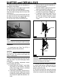
6. Slide the lower cable housing (C, Figure 4)
off the inner wire. Do not lose the ferrule from
either end of the lower cable housing.
7. Release the inner wire from the two housing stops on the right seat stay (A, Figure 5).
8. Slide the tube (B, Figure 5) that sits
between the two housing stops off the inner
wire.
B
SHIFTER CABLE
A
Removal
NOTE
Before removing the shifter cable, note how
the cable is routed along the frame. The new
cable will have to be routed along the same
path.
1. Operate the shifter and move the chain to
the outermost cog.
2. Remove the right side cover from the E-Bike™.
3. Note how the shifter cable is routed along
the top tube and the right seat stay. The cable
will have to be rerouted along the same path.
4. At the derailleur, remove the end cap (A,
Figure 4) from the end of the inner wire.
5. Loosen the pinch-mechanism nut (B, Figure
FIG. 5
9. Pull the shifter cable from the cable inlet in
the right side cover.
10.Slide the upper cable housing from the
inner wire (Figure 6). Do not lose the ferrule
from either end of the upper cable housing.
FIG. 6
C
B
A
FIG. 4
4). Pull the shifter cable from the derailleur
pinch mechanism and out of the barrel
adjuster.
FIG. 7
SHIFTER and DERAILLEUR
11. Remove the shifter from the handlebar as
described in this chapter.
12. Gently pry the cover plate from the inside
face of the shifter housing (Figure 7).
13. Pull the twist unit from the shifter housing.
Slide the shifter housing down the inner wire
and remove it.
14. Push the inner wire into the twister unit until
the barrel end of the inner wire emerges from
the socket in the twister unit (Figure 8).
15. Pull the inner wire from the twister unit.
6-3
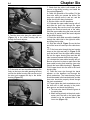
c. Use your hand to move the derailleur to
its innermost position.
d. Hold the derailleur against the stop and
check the guide-pulley alignment.
e. The guide pulley should align with the
innermost cog as shown in Figure 10.
f. If necessary, adjust the inward limit by
turning the L-screw. Tighten the L-screw
to move the derailleur outward. Loosen
the L-screw to move the derailleur
inward.
H Screw
FIG. 8
FIG. 9
NOTE
The shifter inner wire can be removed and
replaced without removing the cable housings.
Installation
A fourth–hand tool (Park Tool BT-2) is
required to perform this procedure
CAUTION
Do not use solvent to clean the shifter housing
and twist unit. The solvent could attack the
plastic in these parts.
1. Clean the shifter housing and twist unit with
soap and water. Dry them thoroughly before
proceeding.
2. Preset the derailleur adjustment screws
before installing the cable.
a. Stand behind the E-Bike™, and check
the position of the derailleur. The guide
pulley should align with the outermost
cog as shown in Figure 9.
b. If necessary, adjust the outward limit by
turning the H-screw. Tighten the H-screw
to adjust the guide pulley inward. Loosen
the H-screw to adjust the derailleur outward.
L Screw
FIG. 10
CAUTION
Lubricate the shifter and cable with Grip Shift
Jonnisnot grease or petroleum jelly. No other
lubricant is suitable for the shifter.
3. Thoroughly lubricate the shifter-housing barrel, spring, cable groove, shifter-housing clip,
and the twist unit with Grip Shift Jonnisnot
grease or petroleum jelly.
4. Feed the free end of the inner wire through
the socket in the twist unit until the barrel end
of the wire is seated in the socket (Figure 11).
6-4
FIG. 11
5. Feed the inner wire along the cable groove
(Figure 12) in the shifter housing and out
through the barrel adjuster.
FIG. 12
6. Fit the twist unit into the shifter housing. Pull
firmly on the inner wire while pressing the twist
unit into the shifter housing. Be sure the end of
the twist unit engages the clip in the shifter
housing (Figure 13).
FIG. 13
Chapter Six
7. Check that the cable is still seated in the
groove in the shifter housing, and install the
cover plate (Figure 7).
8. Check the operation of the shifter. Pull the
inner wire while you operate the shifter. The
inner wire should move in and out, and the
shifter should click along its detents.
9. Slip the shifter onto the handlebar.
10. Lubricate the upper cable housing with oil,
and slide the inner wire through the upper
cable housing. Be sure the inner wire passes
through the ferrule at each end of the cable.
Slide the upper cable along the inner wire until
the ferrule is seated inside the barrel adjuster
at the shifter housing.
11.Route the shift cable around the headlight,
through the cable inlet in the right side cover,
and along the top tube.
12. Slide the tube (B, Figure 5) over the free
end of the inner wire and up to the cable housing.
13. Fit the inner wire through the two housing
stops on the right seat stay (A, Figure 5). Be
sure the ferrule from the upper cable housing
fits into the upper housing stop and that the
tube is secure between both housing stops.
14. Lubricate the lower cable housing with oil.
Be sure a ferrule is in place on each end of the
lower cable housing, and install the inner wire
through the lower cable housing (C, Figure 4).
Fit the upper ferrule into the seat in the lower
housing stop.
15. Feed the inner wire through the barrel
adjuster on the derailleur and through the
pinch mechanism. The lower-housing ferrule
should be seated in the barrel adjuster, and the
inner wire should be properly routed through
the pinch mechanism.
16. Finger tighten the pinch-mechanism nut so
the inner wire is held securely in the pinchplate groove, and check the following:
a. The inner wire should follow the goove in
the pinch plate.
b. When looking directly at the pinch mechanism stud, the tab on the pinch plate
should be on the outboard side of the
inner wire (Figure 14).
SHIFTER and DERAILLEUR
6-5
Derailleur Adjustment
Correct
Pinch plate
Incorrect
Tab
Tab
FIG. 14
17. Loosen the pinch-mechanism nut, and use
the fourth-hand tool to pull the slack from the
inner wire.
18.Torque the pinch-mechanism nut (B, Figure
4) to the specification in Table 4. Check that the
inner cable is still contained within the groove
in the pinch-mechanism plate.
19. Fit an end cap (A, Figure 4) over the end
of the inner wire, and crimp it onto the wire.
20. Install the shifter onto the left handlebar as
described in this chapter.
21. Adjust the derailleur as described in this
chapter.
22. Set the cable tension as described in this
chapter.
DERAILLEUR
Derailleur Lubrication
Apply lubricant to the following points on the
derailleur. See Figure 15.
1. Each edge of the pulley-wheel dust cap.
2. Both ends of each pivot on the parallelogram.
3. Threads of the mounting bolt.
4. Threads of the barrel adjuster.
5. Threads of the pinch-mechanism.
Three screws, the H-, L-, and B-screws, are
used to adjust the derailleur. The H-screw sets
the outward limit of the derailleur’s movement.
The L-screw sets its inward limit. The B-screw
adjusts the distance between the bottom of the
cogset and the derailleur’s guide pulley.
A fourth–hand tool (Park Tool BT-2) is
required to perform this procedure
1. Check the cable attachment to the derailleur
pinch mechanism.
a. Inspect the position of the inner wire in
the pinch-mechanism. The innerwire
should follow the groove in the pinch
plate, and the tab on the pinch plate
should be on the outboard side of the
cable when you look directly at the
pinch-mechanism stud (Figure 14).
b. Loosen the pinch-mechanism nut. Use
the forth-tool to pull the slack from the
inner wire.
c. Torque the pinch-mechanism nut to the
specification in Table 4.
d. Check that the inner cable is still con
tained within the groove in the pinchmechanism plate.
2. Set the derailleur as close as possible to the
cogset by performing the following.
a. Shift the chain to the innermost cog.
b. Completely loosen the B-screw.
c. Back-pedal, and check for bouncing at
the guide pulley (Figure 16). The Bscrew is too loose if bouncing is noticed.
d. Tighten the B-screw one turn, and repeat
the bounce check.
Mounting bolt
B-Screw
Guide
pulley
FIG. 15
Tension pulley
Bouncing
FIG. 16
6-6
3. Set the derailleur’s outward limit by performing the following.
a. Shift the derailleur so the chain is on the
outermost cog.
b. Stand behind the E-Bike™, and check
the position of the derailleur. The
guide pulley should align with the outer
most cog as shown in Figure 9.
c. If necessary, adjust the outward limit by
turning the H-screw. Tighten the Hscrew to adjust the guide pulley inward.
Loosen the H-screw to adjust the
derailleur outward.
4. Set the derailleur’s inward limit by performing the following.
a. Shift the derailleur so the chain rests on
the innermost cog.
b. Stand behind the E-Bike™, and check
the position of the derailleur. The guide
pulley should align with the innermost
cog as shown in Figure 10.
c. If necessary, adjust the inward limit by
turning the L-screw. Tighten the L-screw
to move the derailleur outward. Loosen
the L-screw to move the derailleur
inward.
Setting Cable Tension
A fourth–hand tool (Park Tool BT-2) is
required to perform this procedure.
1. Loosen the nut on the derailleur pinch mechanism.
2. Turn the derailleur barrel adjuster to its full-in
position, and then back out the adjuster three
full turns.
3. Turn the shifter barrel adjuster to its fully-in
position, and then back out the adjuster one
full turn.
NOTE
Do not pull the inner wire so much that the
derailleur begins to move.
4. Use a fourth-hand tool to pull the slack out
of the inner wire.
5. Torque the pinch-mechanism nut to the
specification in Table 4. Check that the inner
wire is still positioned within the pinch-mechanism groove.
Derailleur Installation
1. Lubricate the derailleur as described above.
2. Align the mounting bolt with the hole in the
hanger.
3. Rotate the derailleur clockwise so the stop
tab on the derailleur mounting plate (or the end
of the B-screw) is forward (clockwise) of the
stop tab on the derailleur hanger.
4. Thread the mounting bolt into the hanger but
do not completely secure the bolt at this time.
5. Rotate the derailleur counterclockwise until
the derailleur stop tab presses against the stop
tab on the hanger.
6. Tight the mounting bolt to the torque specification in Table 4.
7-1
Chapter Seven
CHAIN
and CRANKSET
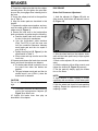
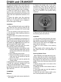
CHAIN
Inspection
The chain inspection tool (Part Tool CC-2C)
is required for this service.
1. Install the chain inspection tool onto the
chain according to the manufacturer’s instructions. Be sure both of the tool’s pegs are inside
a chain link.
2. Rotate the tool’s dial so the pegs press
against the inside of the chain rollers.
3. Read the number opposite the V-notch on
the dial.
a. 0-1 indicates the chain is in good condition.
b. 1-2 indicates the chain is moderately
worn.
c. 2-3 indicates the chain is approaching
the wear limit.
d. 3 or more indicates the chain is worn
beyond the wear limit.
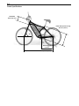
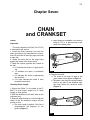
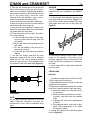
Checking Chain Length
1. Secure the E-bike™ in the stand so the EBike™ is at an angle it would be in if it were
upright on level ground.
2. Shift the derailleur so the chain rides on the
outermost cog.
3. Examine angle formed by a line through the
center of the two derailleur pulleys and the
ground or floor.
a. The chain length is perfect if this line is
perpendicular (90 degrees) to the
ground (Figure 1).
b. Chain length is acceptable if the tension
pulley is 1.75 in. or less forward or rear
ward of the guide pulley.
90˚
FIG. 6
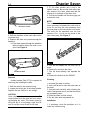
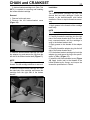
4. Examine the chain.
a. The chain is too long if it sags in the
upper chain run as shown in Figure 2.
b. The chain is too long if the chain contacts
itself or any part of the derailleur after
the chain leaves the tensioner pulley
(Figure 3).
FIG. 7
Chapter Seven
7-2
3. Fit the chain breaker onto a link in the
chain’s lower run. Be sure the chain rollers are
fully seated in the tool’s cradle and that the
driving pin is centered on the chain rivet.
4. Turn the tool handle until the driving pin just
touches the rivet.
Excessive contact
FIG. 3
5. Shift the derailleur so the chain rides on the
innermost cog.
6. Examine the chain as it passes through the
derailleur.
a. If the chain passes through the derailleur
without bending twice, the chain is too
short. See Figure 4.
Insufficient
Bend
Insufficient Bend
FIG. 4
Removal
A chain breaker (Park CT-3) is required for
removing and installing the chain.
1. Shift the chain to the outermost cog.
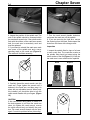
2. Inspect the driving pin of the chain breaker.
Replace the tool if the pin is not straight.
CAUTION
Some chain breakers have two cradles. The
cradle furthest from the guide pin is for removing/installing the chain. The cradle closest to
the guide pin is for adjusting a tight link. Be
sure to use the correct cradle for the task.
NOTE
The rivet should be pressed the minimum distance necessary to separate the chain and no
more. Do not drive the rivet completely from
the inner plate on the inboard side of the chain.
The chain can be separated once the rivet
extends 0.5 to 1.0 mm into the inside of the
inner chain plate. See Figure 5.
FIG. 5
5. Turn the tool handle five full turns, but no
more.
6. Remove the tool from the chain.
7. Flex the chain laterally, and separate the
chain.
8. Remove the chain from the E-Bike™.
Cleaning
1. Immerse the chain in solvent.
2. Use a stiff brush to clean the both sides of
the chain.
3. Use the brush carefully when cleaning the
rollers. Take special care to see that the rollers
are completely clean.
4. Rinse the chain in clean solvent.
5. Dry the chain with compressed air.
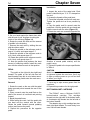
Installation
1. If necessary, move the derailleur so it is
under the outermost cog.
CHAIN and CRANKSET
2. Take the non-riveted end of the chain and
feed it under and around the rear of the tension
pulley on the derailleur. Following the derailleur
cage, route the chain up the front and over the
top of the guide pulley. Once the chain
emerges from the derailleur cage, route it
under and around the outermost cog.
3. Next route the chain around the chainring.
4. Move the chain so the two free ends meet at
the middle of the lower chain run.
5. Join the two ends together by slipping the
end of the inner plate under the rivet protruding inward from the outer plate.
6. Fit the chain tool onto the chain. Pay attention to the following:
a. If the tool has two cradles, fit the chain
over the cradle furthest away from the
tool handle.
b. Be sure the rollers are fully seated on the
tool cradle.
c. Turn the tool handle so the drive pin is
centered on the rivet.
d. Check that the side plates are properly
aligned.
7. Turn the tool handle, and drive the rivet
through the chain until the rivet is centered
within the link. The rivet is properly installed
when an equal amount of rivet protrudes from
the outside of each outer side plate (Figure 6).
7-3
CAUTION
Use oil designed for bicycles. Automotive and
household oils are unsuitable for the E-Bike™
chain.
1. Oil the contact areas between the inner and
outer side plates on each link (A, Figure 7) as
well as the contact areas between the inner
side plates and each end of the rollers (B,
Figure 7).
B
A
B
A
FIG. 7
2. If the chain is installed on the E-Bike™, back
pedal for 30 seconds. If the chain is not
installed, wiggle the chain for 30 seconds. This
helps the lubricant penetrate the crevices in
the chain.
3. Use a clean cloth to wipe excess lubricant
from the chain.
CRANK ARM
Removal
FIG. 6
Lubrication
NOTE
Do not apply excessive amounts of oil to the
chain. Excessive lubrication promotes the
accumulation of dirt, which accelerates chain
wear.
A cotterless crank wrench (Park Tool CCW14R) is required for this service.
1. If the pedal will also be serviced, remove the
pedal from the crank arm.
2. Measure the clearance between the outside
face of the chainring and the right chain stay.
a. Check the clearance on the rear side of
the chainring.
b. Check the chainring clearance at several places, and write down the smallest
value.
c. Compare this value to the specification
in Table 1.
d. The chainring and/or chain stay is damaged if the measurement is not within
the specified range.
3. Loosen and remove the crank-arm mount
ing bolt (Figure 8).
Chapter Seven
7-4
FIG. 8
4. Inspect the position of the spindle end. The
end of the spindle should be recessed within
the crank-arm square hole. If the spindle end is
flush with the surface of the crank-arm square
hole, the crank arm is excessively worn and
must be replaced.
5. If you intend to reinstall the crank arm, mark
one corner of the spindle end and a corresponding mark on the crank arm (Figure 9).
The marks will facilitate assembly.
FIG. 10
7. Turn the crank wrench handle clockwise,
and press the crank arm off the spindle.
8. If you are removing the right arm, remove
the chainring from the chain, and suspend the
chain from the frame with a bungee cord.
Inspection
1. Inspect the spindle flats for signs of a loose
or worn crank arm. The crank-arm marks on
the spindle flats should not extent along the
entire surface of the flat (Figure 11). If they do,
the crank arm is worn and must be replaced.
Good
FIG. 9
6. Carefully thread the crank wrench onto the
crank arm. Finger tighten the wrench until it
bottoms in the crank arm, and then snug it in
place with an adjustable wrench. When properly installed, you should be able to turn the
crank wrench handle with your fingers. (Figure
10)
CAUTION
If the crank wrench body starts to rotate or if
the body appears to pull from the crank arm
when you tighten the crank wrench, remove
the crank wrench body and identify the problem. The crank wrench threads may be damaged. Correct the problem before proceeding.
FIG. 11
FIG. 12
Replace
CHAIN and CRANKSET
2. Inspect the square hole in the crank arm
(Figure 12). The flats of the hole should be
straight and even. Replace the crank arm if its
square hole shows signs of wear or damage.
3. Inspect the crank arm for cracks or other
signs of wear. Pay particular attention to the
area around the mounting holes at either end
of the crank arm. Replace the crank arm if it is
worn.
4. Inspect the spider arms (the crank-arm
spokes) on the right crank arm. Replace the
crank arm if any spider arm is cracked or
shows other signs of damage.
7-5
2. Examine the inboard side of the crankarm/chainring. Note that the chainring is
mounted so the cutout with the tab aligns with
the crank arm (Figure 13). The chainring will
have to be mounted in this position during
installation.
Installation
When installing both crank arms, install the
right crank arm first, and then install the left
crank arm so it is oriented 180° from the right
arm.
1. If you are installing a new right crank arm or
a new chainring, check chainring wobble as
described below.
2. Clean the flats of the spindle with acetone or
alcohol.
3A. If you are reinstalling the old crank arm, fit
the crank arm onto the spindle so the mark you
made on the crank arm aligns with the mark on
the spindle end. (Figure 9) Tap the crank arm
onto the spindle with a plastic mallet.
3B. If installing a new right crank arm and/or
new chainring, perform the following:
a. Rotate the spindle so the reference mark
(from the chainring wobble test) is at the
position that produced the least amount
of wobble.
b. Fit the chainring into the chain.
c. Rotate the derailleur forward, and fit the
crank arm onto the spindle so that the
arm is at 6 o’clock.
d. Tap the crank arm onto the spindle with
a plastic mallet.
4. Apply grease to the crank-arm mounting bolt.
5. Install the crank-arm mounting bolt, and
torque it to the specification in Table 4.
6. Repeat for the left crank arm if necessary.
Be sure the left crank arm is 180˚ opposite the
right crank arm.
CHAINRING
Removal
1. Remove the right crank arm as described in
this chapter.
FIG. 13
3. Remove the five chainring bolts, and remove
the chainring from the crank arm.
Installation
1. Fit the chainring onto the spider (the crankarm spokes) so the chainring mounting holes
align with the threaded hole on the spider.
2. Be sure the cutout with the tab (Figure 13)
aligns with the crank arm.
3. Apply oil to the threads of the chainring
bolts.
4. Finger tighten all five chainring bolts, and
then torque the bolts to the specification in
Table 4.
Chainring Wobble Check
When installing a new right crank arm or reinstalling a right crank arm with a new chainring,
you must install the crank arm in the position
that produces the least amount of chainring
wobble. Perform the following to determine that
position.
1. Place a reference mark in one corner of the
end of right spindle.
2. Rotate the spindle so the reference mark is
at 12 o’clock.
3. Fit the right crank arm onto the spindle so
the arm points to 6 o’clock.
4. Strike the arm with a rubber mallet so the
arm is securely seated on the spindle.
Chapter Seven
7-6
Installation
FIG. 14
5. Set your hand against the frame down tube
with the end of your forefinger touching the
inside of the chainring (Figure 14).
6. Rotate the crank arm and note the amount
of wobble in the chainring.
7. Remove the crank arm by striking the arm
with the rubber mallet.
8. Rotate the spindle so the reference mark is
now at 3 o’clock, and repeat steps 3-7.
9. Rotate the spindle so the reference mark is
at 6 o’clock, and repeat steps 3-7.
10. Rotate the spindle so the reference mark is
at 9 o’clock, and repeat steps 3-7.
11. Note the position that produces the least
amount of chainring wobble. Install the crank
arm with the reference mark in that position.
PEDAL
The pedal on the right side has right-hand
threads. The pedal on the left side has lefthand threads. Keep this in mind when removing and installing pedals onto the crank arms.
Removal
1. Rotate the crank so the arm with the pedal
being removed points towards the rear of the
E-bike™.
2. Place a wrench onto the pedal flats so the
shaft of the wrench is horizontal and pointing
forward.
3. Break the pedal loose.
4. While facing the crank, hold the pedal with
one hand and the wrench with the other.
Rotate the pedal forward (normal pedaling
motion) and remove the pedal.
5. Repeat this procedure for the opposite
pedal.
1. Inspect the ends of the pedal stud. Each
pedal is identified by an “L” or “R” stamped on
the stud.
2. Grease the threads of the pedal stud.
3. Thread the left pedal onto the left crank arm.
Tighten the pedal stud as far as possible by
hand.
4. Face the pedal, and fit a wrench onto the
pedal flats. Hold the pedal with one hand and
hold the wrench with the other (Figure 15).
5. Rotate the crank arm rearward (opposite the
FIG. 15
direction of normal pedal rotation) until the
pedal is snug.
6. Tighten the pedal to the torque specification
in Table 4.
CAUTION
Metal burrs are often created when the pedal
is tightened against the crank arm. Use a rag
to wipe up excess grease so you will not have
to deburr your finger.
7. Use a rag to wipe excess grease from the
crank arm.
8. Repeat this procedure for the right pedal.
BOTTOM-BRACKET CARTRIDGE
The E-Bike™ uses a Chinhaur CH52-73
bottom-bracket cartridge. This cartridge
threads into the right side of the bottom bracket. Its adapter ring threads into the left side of
the bottom bracket.
The adapter ring on this cartridge has standard right-hand threads. The main body, however, has left-hand threads.
CHAIN and CRANKSET
A bottom-bracket-cartridge tool (Park Tool
BBT-2) is required for removing and installing
the bottom-bracket cartridge.
Removal
1. Remove both crank arms.
2. Remove the left bottom-bracket cover
(Figure 16).
7-7
Installation
NOTE
The bottom-bracket cartridge has very fine
threads that are easily damaged. Check the
threads in the bottom-bracket shell before
installation. Dress or tap the threads as necessary.
1. Apply grease to the threads of the cartridge
main body.
NOTE
The main body uses left-hand threads.
FIG. 16
3. Install the bottom-bracket cartridge tool onto
the adapter ring, and remove the ring from the
left side of the bottom-bracket shell (Figure 17).
NOTE
The main body of the cartridge has left-hand
threads. Turn the cartridge clockwise to remove it.
4. Install the bottom-bracket cartridge tool onto
the main body of the cartridge, and remove the
cartridge from the right side of the bottom
bracket.
FIG. 17
2. Carefully threads the cartridge into the right
side of the bottom-bracket shell. Turn the main
body counterclockwise until the cartridge is
snug in the bottom-bracket shell.
3. Apply grease to the threads of the adapter
ring.
4. Carefully thread the adapter ring into the left
side of the bottom-bracket shell.
5. Fit the bottom-bracket-cartridge tool onto the
adapter ring, and torque the ring to the specification in Table 4 (Figure 17).
6. Install the left bottom-bracket cover (Figure
16). Apply Loctite (red) to the threads of the
bottom-bracket-cover screws, and torque the
screws the specification in Table 4.
8-1
Chapter Eight
ELECTRICAL
CONNECTOR IDENTIFICATION
Yellow N
All electrical components in the E-Bike™
are connected to the controller, which is
mounted between the side covers. Refer to
Figure 1. Except for the brake sensor connectors, which are interchangeable, each component’s connector is mated. It can only be connected to its proper place in the E-Bike™.
L
Horn board
M
Behind controller connectors
A
B
K G
J
H
I
Black
Red
C
D
E
Controller board
F
FIG. 1
Controller Board Connectors
Reference Number
A
B
C
D
E
F
Component/Function
Brake sensor, left
Brake sensor, right
Headlight
Taillight/Brake light
Accessory control
Throttle control
Connector Type
2-pin
2-pin
3-pin
6-pin
7-pin
7-pin
Behind Controller Connectors
Reference Number
G
H
I
J
Component/Function
Power (red, from battery terminal block)
Power (black, from battery terminal block)
Motor temperature sensor (2 black wires)
Horn board (yellow and white wires)
Connector Type
Spade
Spade
2-pin
2-pin
Component/Function
Controller (yellow and white wires)
Horn (red and white wires)
Power (red and black wires from
battery terminal block)
Connector Type
2-pin
2-pin
2-pin
Horn Board Connectors
Reference Number
L
M
N
Chapter Eight
8-2
RIGHT SIDE COVER
LEFT SIDE COVER
Removal
Removal
1. Open the door to the battery compartment.
2. Remove the three rubber plugs from the
right side cover holes. Note that the small plug
goes in the lower hole.
3. Remove the three side cover screws. The
screw from the lower hole is smaller than the
two upper screws. It will have to be reinstalled
in the same location.
4. Lift the side cover from the E-Bike™.
5. If necessary, remove the cable inlet cover
from the left side cover. Pull the cable inlet
cover forward and around the head tube until
the tabs clear the left side cover (Figure 2).
1. Be sure the power knob is OFF, and remove
the battery from the battery compartment.
2. Remove the right side cover from the EBike™.
3. Remove the cable inlet cover from the left
side cover.
4. Remove the three battery-compartment
screws (Figure 3) at the front of the battery
compartment.
5. Remove the upper right controller screw (A,
Figure 4). Do not lose the washer behind this
screw.
6. Remove the three left-side-cover screws.
One is located behind the controller (D, Figure
4), one is behind the steering head, and the
third is above the bottom bracket.
FIG. 2
Installation
1. If removed, install the cable inlet cover into
the left side cover. Slide the tabs of the inlet
cover onto the tongues of the side cover
(Figure 2). Gently push the cable inlet cover so
it follows the side-cover contour around the
head tube and rests in place in the left side
cover.
2. Fit the right side cover into place on the EBike™. Be sure no cables or wires are pinched
between the side cover and the frame.
3. Apply Loctite 242 (blue) to the threads of the
side cover mounting screws.
4. Install the screws. Be sure the short screw is
installed in the lower hole. Torque the side
cover mounting screws to the specification in
Table 4.
5. Close and secure the battery compartment
door.
FIG. 3
C
A
B
D
FIG. 4
7. Carefully, pivot the right side cover away
from the E-Bike™ until the battery-compartment passes between the front wheel and forward down tube.
ELECTRICAL
8-3
8A. If you do not need to completely remove
the left side cover form the E-Bike™, use a
wire or bungee cord to suspend the side cover
form the seat.
8B. If the side cover must be completely
removed, perform the following:
a. Squeeze the arms of the rear-brake
caliper together, and disconnect the
rear-brake cable guide from the bracket
on the left caliper arm (A, Figure 5).
b. Loosen the brake-cable pinch bolt (B,
Figure 5), and release the inner cable
end from the pinch mechanism.
c. Carefully pull the brake cable from the
rear inlet in the left side cover.
7. If the brake cable was disconnected from the
rear brake, perform the following:
a. Feed the end of the brake cable inner
wire through the pinch mechanism.
b. Tighten the brake-caliper pinch bolt (B,
Figure 5) to the specification in Table 4.
c. Squeeze the arms of the rear-brake
caliper together, and connect the cable
guide to the bracket on the left caliper
arm (A, Figure 5).
d. If necessary, adjust the brakes.
Installation
1. Be sure the power knob is OFF, and remove
the battery from the battery compartment.
2. Remove the right side cover from the EBike™.
3. Disconnect all the connectors (A-F, Figure
1) from the controller board.
1. If removed, route the rear brake cable
through the rear inlet in the left side cover.
2. Pivot the side cover into place. Carefully fit
the battery compartment door between the
B
A
FIG. 5
front wheel and the forward down tube, and fit
the side cover onto the left side of the EBike™. Be sure all electrical wires and cables
fit into the cable inlet at the front of the left side
cover.
3. Install the three battery-compartment
screws (Figure 3) finger tight.
4. Apply Loctite 242 (blue) to the threads of
each left-side-cover mounting screw, and
install each screw finger tight.
5. Install the upper right controller mounting
screw (A, Figure 4) along with the washer.
Apply Loctite 242 (blue) to the threads of the
screw and finger tighten the screw.
6. Torque the controller mounting screw and
the three side-cover mounting screws to the
specifications in Table 4.
CONTROLLER
Removal
NOTE
On early-production models, the blue ground
wire is secured to the controller heat sink by
the rear controller mounting screw (B, Figure
4). On later-production models, this wire is
secured by a separate ground screw that
mounts to the heat sink just above the rear
controller mounting screw (B, Figure 4).
4. On later-production models, remove the
ground screw and disconnect the blue ground
wire from the heat sink.
5. Hold the controller in place, and remove the
three controller mounting screws (A, B, & C,
Figure 4). When removing the rear controllermounting screw (B, Figure 4), note the two
stepped washers that sit on either side of the
hole in the heat sink. They must be reinstalled
in the same positions during assembly.
6. Lift the controller from the E-bike™, disconnect the four connectors (G-J, Figure 1) from
behind the controller, and then remove the
controller.
Installation
1. Apply Loctite 242 (blue) to the threads of the
controller-mounting screws.
2. Attach the following connectors to their
mates on the back of the controller:
a. The red power connector (G, Figure 1).
Chapter Eight
8-4
b. The black power connector (H, Figure 1).
c. The motor connector (I, Figure 1)
d. The horn-board connector (J, Figure 1).
3. Fit the controller into place in the E-Bike™,
and install the three controller mounting
screws (A, B, & C, Figure 4). Finger tighten the
screws at this point. When installing the rear
mounting screw (B, Figure 4), be sure a
stepped washer fits into each side of the
mounting hole on the heat sink.
4A. On early-production models, be sure the
blue motor ground wire from the motor harness
is installed under the rear controller-mounting
screw (B, Figure 4).
4B. On later-production models, use the
ground screw to secure the blue ground wire to
the controller heat sink. This screw mounts to
the threaded hole above the rear controller
mounting screw (B, Figure 4).
5. Torque the three controller-mounting screws
to the specification in Table 4.
6. Connect the following connectors to their
mates on the controller board:
a. Brake-sensor connectors (A and B,
Figure 1).
b. Headlight connector (C, Figure 1).
c. Taillight/brake-light connector (D, Figure 1).
d. Accessory control connector (E, Figure 1).
e. Throttle control connector (F, Figure 1).
7. Install the right side cover.
A
B
C
QR Housing Disassembly.
1. Roll the seal off the upper cable port (B,
Figure 6) on the housing.
2. Roll the O-ring off the lower cable port (C,
Figure 6) on the housing.
3. Release the latch, and open the housing.
4. Disconnect the QR connector (A, Figure 7).
This is a red and blue connector on some models, red and black on others.
5. Disconnect the temperature-sensor connector (B, Figure 7).
A
B
FIG. 7
QR Housing Assembly
1. Connect the temperature-sensor connector
from the controller to its mate from the motor.
2. Connect the QR connector from the controller to its mate from the motor.
3. Fit the QR connector into place in the QR
housing. Be sure the connection engages the
locating dot in the housing.
4. Fit the temperature-sensor connector into
the housing.
5. Route the motor and controller wires out the
respective ports in the housing.
6. Close the housing lid, and secure the latch.
Be sure the motor and controller wires are not
pinched in the housing or the cable ports when
you close the lid.
FIG. 6
QUICK-RELEASE (QR) CONNECTOR
The QR connector is the electrical connection where the motor connects to the controller.
The QR connector sits inside the QR housing,
which is affixed to the left chain stay (A, Figure
6).
CAUTION
The O-ring and seal must properly installed on
the upper and lower cable ports. They help
keep water out of the QR housing.
6. Roll the O-ring up the motor wire and over
the lower cable port (C, Figure 6) until the Oring rests against the QR housing.
ELECTRICAL
7. Fit the seal (B, Figure 6) over the upper
cable port until its rolled end rests against the
QR housing.
8. Use a cable tie to secure the QR housing to
the left chain stay.
MOTOR
8-5
Installation
1. Apply grease to the axle threads.
2. From the left side of the E-Bike™, position
the wheel so the outmost cog is between the
upper and lower chain runs.
3. Rotate the derailleur rearward so the outmost cog engages the upper chain run.
Removal
The motor is an integral part of the rear
hub. Removing the motor consists of disconnecting the motor at the motor junction, and
then removing the rear wheel. The procedure
is described below.
1. Shift the chain to the outermost rear cog on
the freewheel.
2. Squeeze the top of rear brake arms together and free the rear brake cable from the
bracket on the left arm (A, Figure 5).
FIG. 9
FIG. 8
3. Disconnect the motor from the controller by
disassembling the QR housing as described
above.
4. Remove the hardware that secures the
motor torque arm to the left chain stay (Figure
8).
5. Remove the axle cover from each end of the
axle.
6. Remove the axle nut and washer on each
side of the hub. If necessary, hold one nut tight
while you break the other loose.
7. Rotate the derailleur clockwise (rearward)
around its mounting bolt and lower the wheel
from the frame until the rear cogs clear the
derailleur.
8. Remove the wheel from the left side of the
E-Bike™.
4. Lift the wheel rearward and up into the axle
slots in the dropouts. Be sure the outmost cog
remains engaged with the top chain run.
5. When the wheel is properly installed, the
washer and nut will be outboard of the dropout.
(Figure 9)
6. If removed, loosely reinstall the axle nuts
and washers. Be sure the textured side of the
washers faces inward toward the hub.
7. Finger tighten the axle nuts.
8. Secure the motor torque arm to the frame
seat stay. Apply Loctite 242 (blue) to the
threads of the mounting bolt, and tighten the
nut securely (Figure 8).
9. Assemble the QR housing as described
above.
10. Reconnect the rear brake cable to the
bracket on the left caliper arm (A, Figure 5).
11. Center the wheel between the chain and
seat stays. Move the axle as necessary within
the dropout so the wheel is centered. This is
critical. Take the time to assure that the wheel
is properly centered between the chain stays
and between the seat stays.
12. Also operate the brake to assure that the
rim is centered between the brake pads.
13. Once the wheel is centered, torque the
axle nuts to the specification in Table 4.
Chapter Eight
8-6
HEADLIGHT
Headlight Bulb Replacement
Disassembly
1. Disassemble the headlight as described
above in this chapter.
2. Squeeze the bulb socket contacts together,
and unhook the bulb from the headlight socket.
3. Hook a new bulb onto the socket contacts.
Be sure there are good connections between
the bulb hooks and socket contacts.
4. Fit the socket into the headlight reflector,
and secure the socket in place with the set
screw.
5. Assemble the headlight as described above.
1. Unscrew the bezel (A, Figure 10) from the
headlight housing.
2. Remove the bezel and lens (B, Figure 10).
3. Remove the headlight reflector (A, Figure
11) from the housing.
4. Loosen the set screw (B, Figure 11), and
remove the bulb socket from the headlight
reflector.
Headlight Adjustment
B
A
FIG. 10
C
B
A
C
FIG. 11
Assembly
Adjust the headlight according to
Department of Motor Vehicle regulations in
your state.
1. Set the E-Bike™ on a level surface approximately 25 feet from a wall.
2. Have a friend sit on the bike and hold it vertically. Be sure the tires are inflated to the
proper inflation pressure when adjusting the
headlight.
3. Draw a horizontal line on the wall that is 35
inches above the floor/ground.
4. Turns the headlight on.
5. The main beam of light should be centered
on the horizontal line. That is, there should be
an equal amount of light above and below the
line. If necessary, adjust the headlight by performing the following:
a. Loosen the headlight locknut (Figure 12)
behind the headlight housing.
b. Tilt the headlight housing up or down
until the beam is centered on the horizontal line.
c. Tighten the locknut. Torque the headlight
locknut to the specification in Table 4.
1. Slide the socket into the headlight reflector,
and secure the socket in place with the set
screw (B, Figure 11).
2. Fit the reflector (A, Figure 11) into the headlight housing. Be sure the cutouts in the reflector engage the tabs in the housing.
3. Install the lens (B, Figure 10) so the cutouts
engage the tabs in the headlight housing.
4. Screw the bezel (A, Figure 10) in place. Do
not over tighten the plastic threads.
FIG. 12
ELECTRICAL
8-7
TAILLIGHT
TROUBLESHOOTING
Replacement
General instructions
The LEDs in the taillight cannot be
replaced. If the taillight LEDs burn out, install a
new taillight assembly.
1. Be sure the power knob is OFF, and remove
the battery from the compartment.
2. Disconnect the taillight/brake light connector
under the seat (Figure 13).
Find the symptom that describes the condition
you are trying to correct. Follow that troubleshooting procedure step-by-step until the
problem is corrected. Perform the troubleshooting procedures in the indicated order
unless instructed to proceed to another step.
Before moving on to a next step, reconnect any
part that had been disconnected unless
instructed otherwise.
A. The battery does not beep OK when you
secure the battery in the battery compartment.
FIG. 13
3. Remove the two taillight mounting nuts
(Figure 14), and remove the taillight assembly
from the seat bracket.
1. Turn the headlight on. If the light turns on,
the battery and the connection are fine.
Proceed to step 3.
2. If the headlight does not turn on, push the
bottom of the battery into the battery compartment with your hand. The problem is solved if
the E-Bike™ beeps OK.
3. If the headlight does not come on, check the
battery voltage. Recharge the battery if necessary.
4. Replace the controller.
B. The system beeps GO when the power
knob is turned ON, but the motor does not
operate.
FIG. 14
4. Fit a new taillight assembly in place, and
secure it with the two taillight mounting nuts.
Torque the nuts to the specification in Table 4.
5. Connect the taillight/brake light connector
(Figure 13).
1. Check the operation of the brake sensors by
operating each brake lever. The brake light
should turn on when a brake lever is pulled.
The brake light should also turn off when a
brake lever is released. If the brake light operates properly when each brake lever is pulled
and released, proceed to step 5.
2. Check the brake sensor connectors at the
controller board (A & B, Figure 1). Be sure
each connector securely engages its mate in
the board.
3. Operate each brake lever again. If the brake
light operates properly when each brake lever
is pulled and released, reset the unit by turning
the power knob ON and then OFF. Turn the
power knob ON, and check the operation of
the motor. If the motor does not operate, proceed to step 5.
8-8
4. If the brake light does not operate properly
when a brake lever is pulled and released or if
the brake light is always on, a brake sensor
has failed. Replace the brake lever body with
the defective sensor.
5. Check the throttle control connector (F,
Figure 1). Be sure the connector is securely
connected to the controller.
6. Check the resistance of the throttle.
a. Turn the power knob OFF, and remove
the battery from the battery compartment.
b. Disconnect
the
throttle
control
connector (F, Figure 1) from the
controller board.
c. Measure the resistance between the
black and red terminals in the connector
when the throttle is not applied and
when it is fully applied.
Throttle resistance (black to red
terminals):
No throttle:
10K ± 1K ohms
Full throttle: 10K ± 1K ohms
d. Check the resistance between black and
brown terminals when the throttle is not
applied and when it is fully applied.
Throttle resistance (black to brown
terminals):
No throttle:
500 ± 500 ohms
Full throttle: 5000 ± 500 ohms
e. If any resistance is outside of the specified range, replace the throttle control.
7. Check the output of the controller by performing the following:
a. Attach the positive probe of the voltmeter
to the positive battery terminal (G,
Figure 1) on the controller.
b. Connect the negative probe to the heat
sink on the controller.
c. Turn the power knob ON.The voltage
should read zero. Operate the throttle
and watch the meter. The voltage should
jump to 24 volts. If either reading is outside the specification, replace the controller.
NOTE:
The QR connector (A, Figure 7) is red and
blue in some models but red and black in others.
Chapter Eight
8. Check the connections at the QR connector.
a. Open the QR housing on the left chain
stay (A, Figure 6).
b. Check QR connector (A, Figure 7) and
the temperature-sensor connector (B,
Figure 7). The connector from the motor
must securely engage its mate from the
harness. If the connector is loose, press
it together.
c. Install the battery, turn the power knob
ON, and operate the throttle. If the motor
operates, the connection was the problem. Close the QR housing. If necessary,
secure the housing to the left chain stay
with a cable tie.
9. Check the voltage at the QR connection.
a. Disconnect the QR connector at the QR
housing (A, Figure 7).
b. Connect the probes of a voltmeter to the
red (+) and blue (-) terminals on the harness side of the connection.
c. Turn the power knob ON and operate the
throttle. There should be 24 volts at the
harness side of the connector when the
throttle is operated. If the voltage is with
in specification, replace the motor. If not,
replace the wiring between the QR connector and the controller.
C. The unit does not beep GO when the
power knob is turned ON.
1. Charge the battery. Turn the power knob ON.
If the system beeps GO, the problem is
resolved.
2. Check the operation of the power switch.
a. Turn the power knob OFF, and remove
the battery from the battery compart
ment.
b. Disconnect the throttle control connector (F, Figure 1) from the controller
board.
c. Connect an ohmmeter to the red and
orange terminals in the throttle control connector.
d. Check the continuity when the power
knob is OFF and when it is ON. There
should be no continuity when the switch
is OFF. There should be continuity when
the switch is ON. Replace the throttle
control if it fails either continuity test.
ELECTRICAL
3. Check the temperature-sensor connection
behind the controller (I, Figure 1). Be sure the
connector is secure. Install the battery, and
turn the power knob ON. If the system beeps
GO, you have corrected the problem.
4. Check the temperature-sensor connection in
the QR housing.
a. Open the QR housing, and check that
the temperature-sensor connector is
secure (B, Figure 7).
b. Check system operation by turning the
power knob OFF and then ON. If the
system beep GO, you have corrected
the problem.
5. Check the temperature sensor by performing the following.
a. Disconnect the temperature-sensor connector (B, Figure 7) in the QR housing.
b. Connect a jumper across the terminals in
the harness side of the connector. (The
24-gauge black wires.)
c. Turn the switch ON. The temperature
sensor is bad if the unit beeps GO.
d. If the system does not beep GO, perform
this test at the temperature-sensor connector on the controller (I, Figure 1).
Jump the connector. If the system beeps
GO, the problem is in the wire. Replace
it. If the system does not beep GO,
replace the controller.
D. The headlight does not operate when the
switch is turned on.
1. Turn on the headlight switch and check the
operation of the taillight. Press the horn button
and check the operation of the horn. If the
horn, headlight, and taillight do not operate,
check the three-amp fuse (F3 in the schematic)
inside the controller.
a. Remove the controller, open the controller lid, and inspect the fuse LED.
b. If the LED is on, replace the three-amp
fuse (F3).
c. If the LED is not on, check the fuse (F1)
on the controller fuse module. If you find
a 16-amp fuse, replace it with a 25-amp
fuse. If you find a blown 25-amp fuse,
replace the controller.
2. Check the power by operating the horn. If it
does not sound, charge the battery, and retest
the horn. If the horn sounds, continue with
step 3.
8-9
3. Check the headlight bulb. Replace the bulb
if it is burned out.
4. Check the headlight connector (C, Figure 1).
5. Check the continuity of the headlight
switch.
a. Turn the power knob OFF, and remove
the battery from the battery compart
ment.
b. Disconnect the accessory control connector (E, Figure 1) from the controller
board.
c. Connect an ohmmeter between the blue
and white terminals in the connector.
d. Check the continuity when the headlight
switch is turned OFF and turned ON.
e. There should be no continuity when the
headlight switch is OFF. There should be
continuity when the headlight switch is
ON. Replace the accessory control if it
fails either of these tests.
6. Check the voltage at the bulb socket.
a. Reinstall the battery.
b. Remove the bulb socket from the head
light reflector.
c. Connect a voltmeter’s positive lead to the
socket contact with the black wire.
Connect the voltmeter’s negative lead to
the socket contact with the white wire.
d. Turn the headlight switch ON, and measure the voltage between the contacts.
Voltage should read 24 volts DC. If the
voltage reading is 24 VDC, replace the
bulb or the socket. If the voltage is not
24 volts DC, proceed to step 7.
7. Check the voltage at the headlight wire.
a. Be sure the headlight switch is OFF.
b. Disconnect the headlight socket wires
from the two leads from the headlight
wire.
c. Turn the headlight switch ON, and check
voltage between the white (-) and black
(+) leads of the headlight wire. Voltage
should read 24 volts DC. If voltage is 24
VDC, replace the bulb socket. If the voltage is not 24 VDC, proceed to step 8.
8. Check the continuity of the headlight wire.
a. Be sure the power knob is OFF, and
remove the battery from the battery
compartment.
b. Disconnect the headlight connector (C,
Figure 1) from the controller board.
c. Remove the headlight reflector as
described in this chapter.
8-10
d. Twist the ends of the headlight wire
together (black and white), and check
the continuity across the black and white
terminals in the headlight connector (C,
Figure 1). If there is no continuity,
replace the headlight wire.
E. The horn does not sound when the button is pressed.
1. Turn on the headlight switch and check the
operation of the taillight. Press the horn button
and check the operation of the horn. If the
horn, headlight, and taillight do not operate,
check the three-amp fuse (F3 in the schematic)
inside the controller.
a. Remove the controller, open the controller lid, and inspect the fuse LED.
b. If the LED is on, replace the three-amp
fuse (F3).
c. If the LED is not on, check the fuse (F1)
on the controller fuse module. If you find
a 16-amp fuse replace it with a 25-amp
fuse. If you find a blown 25-amp fuse,
replace the controller.
2. Check the power supply by turning on the
headlight. If the light does not operate, charge
the battery.
3. Check the horn switch by performing the following:
a. Turn the headlight on. The headlight
indicator should light.
b. Press the horn switch. If the indicator
light goes off, the horn switch is okay. If
the indicator does not go off, replace the
accessory control.
4. Check the voltage at the horn.
a. Remove the left side cover.
b. Disconnect the spade connectors from
the back of the horn.
c. Connect a voltmeter’s positive lead to the
red terminal. Connect the voltmeter’s
negative lead to the white terminal.
d. Press the horn button, and measure the
voltage. If the voltage is 24 volts DC,
replace the horn. If the voltage is not 24
volts DC, proceed to step 5.
5. Check the voltage at the horn-board-power
connector.
a. Disconnect the horn-board-power connector (N, Figure 1) from the horn
board.
Chapter Eight
CAUTION
The red and black leads from connector N connect directly to the battery. Power is applied to
this connector whenever the battery is in the
battery compartment.
b. Install the battery into the battery com
partment.
c. Check the voltage at the red (+) and
black (-) terminals on the connector.
d. If the voltage is 24 volts DC, proceed to
step 6. If the voltage is not 24 volts DC,
replace the horn-board-power connector
and wires.
6. Check the voltage from the controller to the
horn board.
a. Disconnect connector L (Figure 1) from
the horn board.
b. Connect a voltmeter to the white (+) and
yellow (-) terminals of connector L.
c. Install the battery if you have not already
done so.
d. Press the button, and check the voltage.
If the voltage reads 24 volts DC, replace
the horn board.
F. The taillight does not turn on when the
headlight switch is ON.
1. Turn on the headlight switch and check the
operation of the taillight. Press the horn button
and check the operation of the horn. If the
horn, headlight, and taillight do not operate,
check the three-amp fuse (F3 in the schematic)
inside the controller.
a. Remove the controller, open the controller lid, and inspect the fuse LED.
b. If the LED is on, replace the three-amp
fuse (F3).
c. If the LED is not on, check the fuse (F1)
on the controller fuse module. If you find
a 16-amp fuse replace it with a 25-amp
fuse. If you find a blown 25-amp fuse,
replace the controller.
2. Press the horn button to check power flow. If
the horn sounds, continue. If not, charge the
battery.
3. Check the taillight/brake light connector (D,
Figure 1) at the controller board. Be sure it is
securely connected to the board.
4. Check the taillight switch by performing the
following.
a. Turn the headlight switch on and check
the headlight LED.
ELECTRICAL
b. If the LED turns on, the switch is fine. If
it does not operate, replace the accessory control.
5. Check the voltage at the taillight/brake light
connector.
a. Disconnect the taillight/brake light connector (Figure 13) under the seat.
b. Install the battery into the battery compartment if you have not already done so.
c. Connect a voltmeter to the brown (-) and
black (+) terminals on the controller side
of the connector.
d. Turn the headlight switch ON, and check
the voltage at the connector. If the voltage is 24 volts DC, replace the taillight/brake light assembly. If the voltage
is not 24 volts DC, proceed to step 6.
6. Check the continuity of the controller-to-taillight/brake light wire.
a. Be sure the power knob is off, and
remove the battery from the battery
compartment.
b. Disconnect the taillight/brake light connector (Figure 13) under the seat.
c. Disconnect the taillight/brake light connector (D, Figure 1) from the controller
board.
d. Place a jumper across the brown and
black terminals in the connector at the
controller end of the wire.
e. Connect an ohmmeter to the brown and
black terminals at the taillight/brake light
end of the wire, and check the continuity
of the wire.
f. If there is no continuity, replace the taillight/brake-light-to-controller wire.
G. The brake light does not operate.
1. Turn on the headlight switch and check the
operation of the taillight. Press the horn button
and check the operation of the horn. If the
horn, headlight, and taillight do not operate,
check the three-amp fuse (F3 in the schematic)
inside the controller.
a. Remove the controller, open the controller lid, and inspect the fuse LED.
b. If the LED is on, replace the three-amp
fuse (F3).
c. If the LED is not on, check the fuse (F1)
on the controller fuse module. If you find
a 16-amp fuse, replace it with a 25-amp
fuse. If you find a blown 25-amp fuse,
replace the controller.
8-11
2. Turn the headlight on to check the power. If
the light does not operate, charge the battery.
3. Check the brake sensor connectors (A and
B, Figure 1) at the controller board. Each
should be secure.
4. Check the output from the brake sensor.
a. Disconnect one of the brake-sensor
connectors from the controller.
b. Connect an ohmmeter to the terminals in
the connector.
c. Operate the brake lever for that side, and
check the continuity.
d. There should be continuity when the
brake lever is applied but no continuity
when the lever is released.
e. Replace the brake lever body if the brake
sensor fails either of these tests.
Proceed to step 6 if the brake sensor
passes both tests.
5. Perform this test on the other brake sensor.
6. Check the voltage at the taillight/brake light
connector.
a. Disconnect the taillight/brake light connector (Figure 13) under the seat.
b. Install the battery into the battery compartment if you have not already done
so.
c. Connect a voltmeter to the black (+) and
yellow (-) terminals on the controller side
of the connector.
d. Operate a brake lever, and check the
voltage at the connector. If the voltage is
24 volts DC, replace the taillight/brake
light assembly.
Wiring Diagram
8-13
EV Global Motors Company
10900 Wilshire Blvd. Suite 310
Los Angeles, California 90024
USA
310-208-7076 tel / 310-208-2444 fax
www.ebike.com
P/N: LIT-82001-00-00
a Lee Iacocca Enterprise