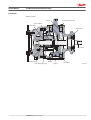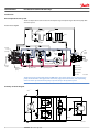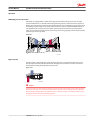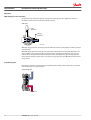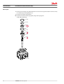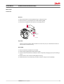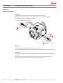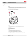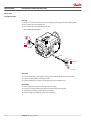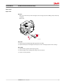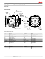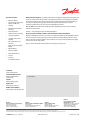
1
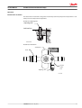
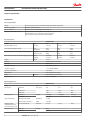
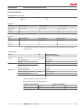
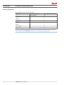
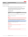
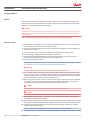
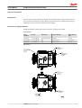
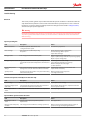
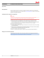
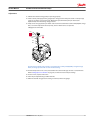
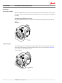
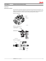
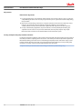
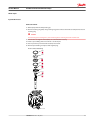
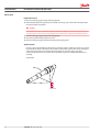
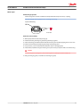
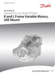
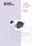
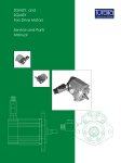
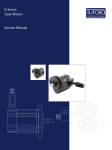
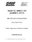
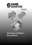
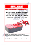
MAKING MODERN LIVING POSSIBLE
Service Manual
Closed Circuit Axial Piston Pumps
LPV
powersolutions.danfoss.com
Service Manual
LPV Closed Circuit Axial Piston Pumps
Revision history
Table of revisions
2
Date
Changed
Rev
July 2015
Danfoss layout
0100
November 2006
First printing
A
11004904 • Rev 0100 • July 2015
Service Manual
LPV Closed Circuit Axial Piston Pumps
Contents
Introduction
Operation
Technical specifications
Overview..............................................................................................................................................................................................4
Warranty.............................................................................................................................................................................................. 4
General instructions........................................................................................................................................................................ 4
Safety Precautions............................................................................................................................................................................5
Symbols used in Danfoss literature............................................................................................................................................6
Design...................................................................................................................................................................................................6
Direct displacement drive system.............................................................................................................................................. 8
LPV Pump schematic diagram.....................................................................................................................................................8
HPRV (High pressure relief valve)............................................................................................................................................... 9
Bypass function................................................................................................................................................................................. 9
CPRV (Charge pressure relief valve)........................................................................................................................................ 10
Loop flushing valve....................................................................................................................................................................... 10
Neutral return mechanism..........................................................................................................................................................11
Specifications...................................................................................................................................................................................12
Fluid and filter recommendations
Fluid and filter recommendations........................................................................................................................................... 15
Startup procedures
Pressure measurements
Troubleshooting
Adjustments
Minor repair
Torque chart
General ..............................................................................................................................................................................................16
Start-up procedure........................................................................................................................................................................ 16
Required tools................................................................................................................................................................................. 17
Port locations and gauge installation.....................................................................................................................................17
Overview........................................................................................................................................................................................... 18
System operating hot...................................................................................................................................................................18
Transmission operates normally in one direction only.................................................................................................... 18
System will not operate in either direction.......................................................................................................................... 18
System noise or vibration........................................................................................................................................................... 19
Sluggish system response...........................................................................................................................................................19
Pump adjustment.......................................................................................................................................................................... 20
Standard procedures, inspections, and adjustments....................................................................................................... 20
Charge pressure relief valve adjustments.............................................................................................................................20
System check and HPRV.............................................................................................................................................................. 22
Checking for proper HPRV valve operation.................................................................................................................... 22
Loop flushing valve....................................................................................................................................................................... 22
Neutral return mechanism..........................................................................................................................................................23
Leveling swashplate with pump installed on machine....................................................................................................24
Input shaft and seal....................................................................................................................................................................... 25
Trunion seal......................................................................................................................................................................................29
High Pressure Relief Valves.........................................................................................................................................................30
Charge pressure relief valve.......................................................................................................................................................31
Loop flushing valve....................................................................................................................................................................... 32
Bypass valve..................................................................................................................................................................................... 33
Coupling............................................................................................................................................................................................34
Fasteners and plugs...................................................................................................................................................................... 35
Fastener size and torque chart..................................................................................................................................................35
Plug size and torque chart..........................................................................................................................................................35
11004904 • Rev 0100 • July 2015
3
Service Manual
LPV Closed Circuit Axial Piston Pumps
Introduction
Overview
This manual includes information for the installation, maintenance, and minor repair of the LPV pump. It
includes a description of the unit and its individual components, troubleshooting information, and minor
repair procedures.
Performing minor repairs requires the unit to be removed from the vehicle/machine. Thoroughly clean
the unit before beginning maintenance, or repair activities. Since dirt and contamination are the greatest
enemies of any type of hydraulic equipment, follow cleanliness requirements strictly. This is especially
important when changing the system filter and when removing hoses or plumbing.
A worldwide network of Danfoss Global Service Partners is available for major repairs. Danfoss Global
Service Partners are trained by the factory and certified on a regular basis. You can locate your nearest
Global Service Partner using the distributor locator at www.sauer-danfoss.com. Click on the Sales and
Service link.
Warranty
Performing installation, maintenance, and minor repairs according to the procedures in this manual will
not affect your warranty. Major repairs requiring the removal of a unit’s rear cover or front flange voids
the warranty unless done by a Danfoss Global Service Partner.
General instructions
Follow these general procedures when repairing Series LPV variable displacement closed circuit pumps.
Remove the unit
Prior to performing major repairs, remove the unit from the vehicle/machine. Chock the wheels on the
vehicle or lock the mechanism to inhibit movement. Be aware that hydraulic fluid may be under high
pressure and / or hot. Inspect the outside of the pump and fittings for damage. Cap hoses after removal
to prevent contamination.
Keep it clean
Cleanliness is a primary means of assuring satisfactory pump life, on either new or repaired units. Clean
the outside of the pump thoroughly before disassembly. Take care to avoid contamination of the system
ports. Cleaning parts by using a clean solvent wash and air drying is usually adequate.
As with any precision equipment, all parts must be kept free of foreign materials and chemicals. Protect
all exposed sealing surfaces and open cavities from damage and foreign material. If left unattended,
cover the pump with a protective layer of plastic.
Lubricate moving parts
During assembly, coat all moving parts with a film of clean hydraulic oil. This assures that these parts will
be lubricated during start-up.
Replace all O-rings and gaskets
4
11004904 • Rev 0100 • July 2015
Service Manual
LPV Closed Circuit Axial Piston Pumps
Introduction
It is recommended that all O-rings be replaced. Lightly lubricate all O-rings with clean petroleum jelly
prior to assembly.
Secure the unit
For major repair, place the unit in a stable position with the shaft pointing downward. It will be necessary
to secure the pump while removing and torquing the endcap bolts.
Safety Precautions
Always consider safety precautions before beginning a service procedure. Protect yourself and others
from injury. Take the following general precautions whenever servicing a hydraulic system.
Unintended Machine Movement
W
Warning
Unintended movement of the machine or mechanism may cause injury to the technician or bystanders.
To protect against unintended movement, secure the machine or disable/disconnect the mechanism
while servicing.
Flammable Cleaning Solvents
W
Warning
Some cleaning solvents are flammable. To avoid possible fire, do not use cleaning solvents in an area
where a source of ignition may be present.
Fluid Under Pressure
W
Warning
Escaping hydraulic fluid under pressure can have sufficient force to penetrate your skin causing serious
injury and/or infection. This fluid may also be hot enough to cause burns. Use caution when dealing with
hydraulic fluid under pressure. Relieve pressure in the system before removing hoses, fittings, gauges, or
components. Never use your hand or any other body part to check for leaks in a pressurized line. Seek
medical attention immediately if you are cut by hydraulic fluid.
Personal Safety
W
Warning
Protect yourself from injury. Use proper safety equipment, including safety glasses, at all times.
Hazardous Material
W
Warning
Hydraulic fluid contains hazardous material. Avoid prolonged contact with hydraulic fluid. Always
dispose of used hydraulic fluid according to state, and federal environmental regulations.
11004904 • Rev 0100 • July 2015
5
Service Manual
LPV Closed Circuit Axial Piston Pumps
Introduction
Symbols used in Danfoss literature
WARNING may result in injury
Tip, helpful suggestion
CAUTION may result in damage to product or
property
Lubricate with hydraulic fluid
Reusable part
Apply grease / petroleum jelly
Non-reusable part, use a new part
Apply locking compound
Non-removable item
Inspect for wear or damage
Option - either part may exist
Clean area or part
Superseded - parts are not interchangeable
Be careful not to scratch or damage
Measurement required
Note correct orientation
Flatness specification
Mark orientation for reinstallation
Parallelism specification
Torque specification
External hex head
Press in - press fit
Internal hex head
Pull out with tool – press fit
Torx head
Cover splines with installation sleeve
O-ring boss port
Pressure measurement/gauge location or
specification
The symbols above appear in the illustrations and text of this manual. They are intended to communicate
helpful information at the point where it is most useful to the reader. In most instances, the appearance
of the symbol itself denotes its meaning. The legend above defines each symbol and explains its purpose.
Design
LPV represents a family of hydrostatic pumps for low to medium power applications with maximum
pressures up to 345 bar [5000 psi]. These pumps can be applied with other products in a system to
transfer and control hydraulic power.
LPV pumps provide an infinitely variable speed range between zero and maximum in both forward and
reverse modes of operation. LPV pumps come in three displacements (25 cm3 [1.53 in3], 30 cm3 [1.83
in3], and 35 cm3 [2.32 in3]).
LPV pumps are compact, high power density units. All models use the parallel axial piston / slipper
concept in conjunction with a tiltable swashplate to vary the pump’s displacement. Reversing the angle
of the swashplate reverses the flow of fluid from the pump, reversing the direction of rotation of the
motor output.
LPV pumps are provided with an internal neutral return mechanism for ease of installation, and are
available with optional loop flushing for circuit flexibility. LPV pumps are designed to receive charge flow
from an auxiliary circuit or from a gear pump mounted on the auxiliary mounting pad. LPV pumps feature
an SAE A auxiliary mounting pad to accept auxiliary hydraulic pumps for use in complementary hydraulic
systems.
LPV pumps include a trunnion style direct displacement control.
6
11004904 • Rev 0100 • July 2015
Service Manual
LPV Closed Circuit Axial Piston Pumps
Introduction
LPV cross section
Trunion
Tapered roller bearing
Cylinder block
Valve plate
Ball bearing
Input shaft
Needle bearing
Piston
Cylinder block spring
11004904 • Rev 0100 • July 2015
Swashplate
Slipper
P106 271E
7
Service Manual
LPV Closed Circuit Axial Piston Pumps
Introduction
Direct displacement drive system
The direct displacement control varies the swashplate angle. Swashplate angle determines pump flow
and motor speed.
Pictorial circuit diagram
Heat exchanger
bypass
Reservoir
Filter
Heat
exchanger
Cylinder
block
assembly
Charge relief
valve
OMS
orbital
motor
Bypass
valve
Output
shaft
Charge pump
Input
shaft
Suction flow
Variable
displacement
pump
HPRV valves
Charge pressure
Loop flushing valves
Servo pressure
High pressure
Case flow
P100 586E
The diagram shows an LPV pump driving an OMR motor. The system shown uses an external charge
pump and external filter. Charge pressure relief valves, high pressure relief valves, and loop flushing
valves are shown separated from the pump to provide clarity to the hydraulic system.
LPV Pump schematic diagram
Charge pressure
inlet
L2
Port A
Port B
L1
8
11004904 • Rev 0100 • July 2015
P106 287E
Service Manual
LPV Closed Circuit Axial Piston Pumps
Operation
HPRV (High pressure relief valve)
LPV pumps are equipped with a combination high pressure relief and charge check valve. The highpressure relief function is a dissipative (with heat generation) pressure control valve for the purpose of
limiting excessive system pressures. The charge check function acts to replenish the low-pressure side of
the working loop with charge oil. Each side of the transmission loop has a dedicated HPRV valve that is
non-adjustable with a factory set pressure. When system pressure exceeds the factory setting of the
valve, oil is passed from the high pressure system loop, into the charge gallery, and into the low pressure
system loop via the charge check.
HPRV valve
P106 273E
Bypass function
The LPV contains a dedicated bypass valve. The bypass function is activated when the bypass valve is
mechanically backed out 3 full turns (maximum). The bypass function allows a machine or load to be
moved without rotating the pump shaft or prime mover.
Bypass valve
P106 286E
C
Caution
Excessive speeds and extended load/vehicle movement must be avoided. The load or vehicle should be
moved not more than 20% of maximum speed and for a duration not exceeding 3 minutes. Damage to
drive motor(s) is possible. When the bypass function is no longer needed care should be taken to reseat
the bypass valves to the normal operating position.
11004904 • Rev 0100 • July 2015
9
Service Manual
LPV Closed Circuit Axial Piston Pumps
Operation
CPRV (Charge pressure relief valve)
An internal charge relief valve regulates charge pressure. Charge pressure is supplied to maintain a
minimum pressure in the low side of the transmission loop.
CPRV valve
Case
pressure
Charge
pressure
P106 274E
Minimum charge pressure is the lowest pressure allowed to maintain a safe working condition in the low
side of the loop.
Maximum charge pressure is the highest charge pressure allowed by the charge relief adjustment, and
which provides normal component life. The charge pressure setting listed in the order code is the set
pressure of the charge relief valve with the pump in neutral, operating with 5 gpm of charge flow. The
charge pressure setting is referenced to case pressure. Charge pressure is the differential pressure above
case pressure.
Loop flushing valve
LPV pumps incorporate an optional integral loop flushing valve, which removes heat and contaminants
from the main loop at an increased rate.
Loop flushing valve
P106 276E
10
11004904 • Rev 0100 • July 2015
Service Manual
LPV Closed Circuit Axial Piston Pumps
Operation
Neutral return mechanism
The neutral return mechanism is designed to mechanically return the pump to zero displacement. A cam
allows precise zero displacement adjustment.
Neutral return adjusting cam
Adjusting cam
Lock/seal nut
P106 277E
Neutral return mechanism
Swashplate
Shaft
Adjusting cam
Neutral
return
arm
P106 278E
11004904 • Rev 0100 • July 2015
11
Service Manual
LPV Closed Circuit Axial Piston Pumps
Technical specifications
Specifications
General specifications
Design
Axial piston pump of trunion swashplate design with variable displacement
Direction of rotation
Clockwise, counterclockwise
pipe connections
Main pressure ports: SAE straight thread O-ring boss
Recommended installation position
Pump installation recommended with control position on the top or side.
Consult Danfoss for non conformance to these guidelines.
The housing must always be filled with hydraulic fluid.
Physical properties
Displacement
Feature
Unit
25
30
35
Maximum Displacement
cm³ [in³]
25 [1.53]
30 [1.83]
35 [2.14]
Flow at rated speed (theoretical)
l/min
[US gal/min]
85.2
[22.5]
104.9
[27.7]
137.0
[36.2]
Input torque at maximum displacement (theoretical)
N•m/ bar
[lbf•in/1000 psi]
0.4
[244]
0.5
[291]
0.6
[340]
Mass moment of inertia of internal rotating components kg•m²
[slug•ft²]
0.001670
[0.0012]
0.001580
[0.00120]
0.001530
[0.00113]
Weight
23 [51]
kg [lb]
Rotation
Clockwise, Counterclockwise
Mounting
SAE B 2 bolt
Auxiliary mounting
SAE J744 A 9T, SPCL 11T
System ports (type)
1 1/16-12 UNF-2B ORB
System ports (location)
Twin radial
Control types
Direct displacement control
Shafts
Splined
Case drain ports
Splined SAE13 tooth, 15 tooth
1 1/16-12 SAE ORB
Operating parameters
Displacement
Rating
Units
25
30
35
Input speed
min-1 (rpm)
Working pressure
minimum
500
500
500
continuous
3400
3500
3600
maximum
3950
4150
4300
210 [3045]
175 [2540]
140 [2030]
63,000
37,000
continuous
bar [psi]
maximum
External shaft loads
345 [5000]
External moment (Me)
N•m [lbf•in]
7.7 [68]
Thrust in (Tin), out (Tout)
N [lbf]
750 [169]
Bearing life (max.
swashplate angle and
max. continuous speed)
at 210 bar [3045 psi]
B10 hours
120,000
Charge pressure
minimum
bar [psi]
6 [87]
maximum
12
11004904 • Rev 0100 • July 2015
20 [300]
Service Manual
LPV Closed Circuit Axial Piston Pumps
Technical specifications
Operating parameters (continued)
Case pressure
rated
bar [psi]
maximum
2 [29]
6 [87]
Sound levels1
dB(A)
100 bar [1450 psi]
200 bar [2900 psi]
300 bar [3451 psi]
Displ. cm³ [in³]
1000 min-1(rpm)
1000 min-1(rpm)
1000 min-1(rpm)
25 [1.53]
62
66
68
35 [2.14]
61
66
69
dB(A)
100 bar [1450 psi]
200 bar [2900 psi]
300 bar [3451 psi]
Displ. cm³ [in³]
3000 min-1(rpm)
3000 min-1(rpm)
3000 min-1(rpm)
25 [1.53]
70
74
76
35 [2.14]
71
75
80
Sound levels
1 Sound data was collected in a semi-anechoic chamber. Values have been adjusted (-3 dB) to reflect
anechoic levels.
Fluid specifications
Feature
Viscosity
Minimum
Filtration
Displacement cm³ [in³]
25 [1.53], 30 [1.83], 35 [2.14]
mm 2/s [SUS]
7 [47]
Recommended range
12-60 [66-278]
Maximum
1600 [7500]
Temperature Range Minimum
2
Unit
C° [F°]
-40 [-40]
Rated
82 [180]
Maximum intermittent
100 [212]
Cleanliness per ISO 4406
Efficiency (charge pressure filtration)
22/18/13
β-ratio
Efficiency (suction filtration)
Recommended inlet screen mesh size
β15-20= 75 (β10≥ 10)
β35-45= 75 (β10≥ 2)
μm
100 - 125
2At the hottest point, normally case drain port.
Mounting flange allowable overhung parameters
Continuous load moment (Mc)
Shock load moment (Ms)
N•m
[lbf•in]
N•m
[lbf•in]
361
[3200]
617
[5470]
11004904 • Rev 0100 • July 2015
13
Service Manual
LPV Closed Circuit Axial Piston Pumps
Technical specifications
Mounting flange G-factors for sample applications
Application
Continuous (vibratory)
acceleration (Gc)
Maximum (shock) acceleration
(Gs)
Skid steer loader
6
10
Trencher
(rubber tires)
6
8
Asphalt paver
6
6
Windrower
6
5
Aerial lift
6
4
Turf care vehicle
6
4
Vibratory roller
6
10
Applications experiencing extreme resonant vibrations may require additional pump support. Refer to
LPV Technical Information 520L0954 for information concerning mounting flange loads.
14
11004904 • Rev 0100 • July 2015
Service Manual
LPV Closed Circuit Axial Piston Pumps
Fluid and filter recommendations
Fluid and filter recommendations
To ensure optimum life, perform regular maintenance of the fluid and filter. Contaminated fluid is the
main cause of unit failure. Take care to maintain fluid cleanliness when servicing.
Check the reservoir daily for proper fluid level, the presence of water, and rancid fluid odor. Fluid
contaminated by water may appear cloudy or milky or free water may settle in the bottom of the
reservoir. Rancid odor indicates the fluid has been exposed to excessive heat. Change the fluid
immediately if these conditions occur. Correct the problem immediately.
Inspect vehicle for leaks daily.
Fluid and filter change interval
Reservoir type
Max oil change interval
Sealed
2000 hours
Breather
500 hours
Change the fluid and filter per the vehicle/machine manufacturer’s recommendations or at these
intervals:
First fluid change recommended at 500 hours.
C
Caution
High temperatures and pressures will result in accelerated fluid aging. More frequent fluid changes may
be required.
Change the fluid more frequently if it becomes contaminated with foreign matter (dirt, water, grease,
etc.) or if the fluid is subjected to temperature levels greater than the recommended maximum.
Dispose of used hydraulic fluid properly. Never reuse hydraulic fluid.
Change filters whenever the fluid is changed or when the filter indicator shows that it is necessary to
change the filter. Replace all fluid lost during filter change.
W
Warning
Hazardous material
Hydraulic fluid contains hazardous material. Avoid contact with hydraulic fluid. Always dispose of used
hydraulic fluid according to state, and federal environmental regulations.
Hazardous material
W
Warning
W Warning
Hydraulic fluid contains hazardous material. Avoid contact with hydraulic fluid. Always dispose of used
hydraulic fluid according to state, and federal environmental regulations.
11004904 • Rev 0100 • July 2015
15
Service Manual
LPV Closed Circuit Axial Piston Pumps
Startup procedures
General
Follow this procedure when starting-up a new pump installation or when restarting an installation in
which the pump has been removed and re-installed on a machine. Ensure pump has been thoroughly
tested on a test stand before installing on a machine.
W
Warning
Unintended movement of the machine or mechanism may cause injury to the technician or bystanders.
To protect against unintended movement, secure the machine or disable/disconnect the mechanism
while servicing.
Prior to installing the pump, inspect for damage that may have occurred during shipping.
Start-up procedure
1. Ensure that the machine hydraulic oil and system components (reservoir, hoses, valves, fittings, and
heat exchanger) are clean and free of any foreign material.
2. Install new system filter element(s) if necessary. Check that inlet line fittings are properly tightened
and there are no air leaks.
3. Install the pump. Install a 50 bar [1000 psi] gauge in the charge pressure gauge port M3.
4. Fill the housing by adding filtered oil in the upper case drain port.
5. Fill the reservoir with hydraulic fluid of the recommended type and viscosity. Use a 10-micron
reservoir filler filter. Ensure inlet line from reservoir to pump is filled.
6. Disconnect the pump from control.
After start-up the oil level in the reservoir may drop due to filling of the system components. Check
the level in the reservoir to maintain a full oil level throughout the start-up.
W
Warning
Damage to hydraulic components may occur if the oil supply is not maintained.
7. Use a common method to disable the engine to prevent the engine from starting. Crank the starter
for several seconds. Do not to exceed the engine manufacturer’s recommendation. Wait 30 seconds
and then crank the engine a second time as stated above. This operation helps remove air from the
system lines. Refill the reservoir to recommended full oil level.
8. When charge pressure begins to appear, enable and start engine. Let the engine run for a minimum
of 30 seconds at low idle to allow the air to work itself out of the system. Check for leaks at all line
connections and listen for cavitation. Check for proper fluid level in reservoir.
C
Caution
Air entrapment in oil under high pressure may damage hydraulic components.
C
Caution
Do not run at maximum pressure until system is free of air and fluid has been thoroughly filtered.
9. When adequate charge pressure is established, increase engine speed to normal operating rpm to
further purge residual air from the system.
10. Shut off engine. Connect pump control. Start engine, checking to be certain pump remains in neutral.
Run engine at normal operating speed and carefully check for forward and reverse control operation.
11. Continue to cycle between forward and reverse for at least five minutes to bleed all air and flush
system contaminants out of loop.
Normal charge pressure fluctuation may occur during forward and reverse operation.
12. Check that the reservoir is full. Remove charge pressure gauge. The pump is now ready for operation.
16
11004904 • Rev 0100 • July 2015
Service Manual
LPV Closed Circuit Axial Piston Pumps
Pressure measurements
Required tools
The service procedures described in this manual can be performed using common mechanic’s hand
tools. Special tools, if required, are shown. When testing system pressures, calibrate pressure gauges
frequently to ensure accuracy. Use snubbers to protect gauges.
Port locations and gauge installation
The following table and drawing show the port locations and gauge sizes needed.
Port information
Port
identifier
Port size
Wrench size
Pressure obtained
Gauge size, bar
[psi]
Case drain
1 1/16-12 UNF 2B
15 mm internal hex
Case drain
10 [100]
Port A, Port B
1 1/16-12 UNF 2B
N/A
System pressure
600 [10,000]
Charge inlet
7/8-14 UNF 2B
N/A
Charge pressure
50 [1000]
Port locations
7/8 -14
SAE straight thread
O-ring boss
charge inlet
1 1/16 -12
SAE straight thread
O-ring boss
case drain
7/8 -14
SAE straight thread
O-ring boss
charge pressure
relief valve
1 1/16 -12
SAE straight thread
O-ring boss
system port A
1 1/16 -12
SAE straight thread
O-ring boss
system port B
1 1/16 -12
SAE straight thread
O-ring boss
case drain (alternate)
11004904 • Rev 0100 • July 2015
P106 323E
17
Service Manual
LPV Closed Circuit Axial Piston Pumps
Troubleshooting
Overview
This section provides general steps to follow if undesirable system conditions are observed. Follow the
steps listed until the problem is solved. Some of the items will be system specific. For areas covered in
this manual, a section is referenced. Always observe the safety precautions listed in Safety precautions,
and related to your specific equipment.
W
Warning
Unintended movement of the machine or mechanism may cause injury to the technician or bystanders.
To protect against unintended movement, secure the machine or disable/disconnect the mechanism
while servicing.
System operating hot
Item
Description
Action
Oil level in reservoir.
Insufficient hydraulic fluid will not meet
cooling demands of system.
Fill reservoir to proper level.
Heat exchanger.
Heat exchanger not sufficiently cooling
the system.
Check air flow and input air temperature
for heat exchanger. Clean, repair or
replace heat exchanger.
Charge pressure.
Low charge pressure will overwork system.
Measure charge pressure. Inspect and
adjust or replace charge relief valve. Inspect charge pump.
Repair or replace charge pump.
Charge pump inlet vacuum.
High inlet vacuum will overwork system. A dirty filter will
increase the inlet vacuum. Inadequate line size will restrict
flow.
Check charge inlet vacuum. If high,
inspect inlet filter and replace as necessary.
Check for adequate line size, length
or other restrictions
System relief pressure
settings.
If the system relief valves are worn, contaminated or, valve
settings are too low, the relief valves will be overworked.
Verify settings of high pressure relief valves and
replace valves as necessary.
System pressure.
Frequent or long term operation over system relief setting
will create heat in system
Measure system pressure. If pressure
is too high, reduce loads.
Transmission operates normally in one direction only
Item
Description
Action
Control linkage
Control linkage operating improperly
Repair/replace control linkage
Interchange high pressure
relief valves
Interchanging the high pressure relief valves will show if
the problem is related to the valve function.
If the problem changes direction, replace the valve that
does not operate correctly.
Ensure bypass valve is
closed.
Open bypass will cause both directions to be inoperative.
Close/repair bypass function.
System will not operate in either direction
Item
Description
Action
Ensure bypass valve is
closed.
If bypass valve is open, the system loop will be
depressurized.
Close bypass valve.
Charge pressure with pump
in neutral
Low charge pressure insufficient to recharge system loop
Measure charge pressure with the pump in neutral. If
pressure is low, go to Pump charge relief valve
18
11004904 • Rev 0100 • July 2015
Service Manual
LPV Closed Circuit Axial Piston Pumps
Troubleshooting
Item
Description
Action
Charge pressure with pump
in stroke
Low charge pressure resulting from elevated loop leakage.
Isolate pump from motor by blocking system ports. With
pump in partial stroke and engaged for only a few seconds,
check pump charge pressure. Low charge pressure
indicates a malfunctioning pump. Continue to next step.
Good charge pressure indicates a malfunctioning motor or
other system component. Check motor charge relief
operation (if present).
Pump charge relief valve.
A pump charge relief valve that is leaky, or contaminated,
or set too low will depressurize the system.
Adjust or replace pump charge relief valve as necessary
Charge pump inlet filter.
A clogged filter will under supply system loop.
Inspect filter and replace if necessary.
Charge pump.
A malfunctioning charge pump will provide insufficient
charge flow.
Repair or replace the charge pump.
System pressure
Low system pressure does not provide enough power to
move load
Measure system pressure. Continue to next step.
System relief valves
Defective high pressure relief valves cause system pressure
to be low
Repair or replace high pressure relief valves.
Item
Description
Action
Reservoir oil level
Low oil level leads to cavitation.
Fill reservoir.
Aeration of the oil/pump
inlet vacuum
Air in system decreases efficiency of units and controls. Air
in system is indicated by excessive noise in pump, foaming
in oil, and hot oil.
Find location where air is entering into the system and fix.
Check that inlet line is not restricted and is proper size.
Cold oil
If oil is under cold conditions, it may be too viscous for
proper function and pump cavitates
Allow the oil to warm up to its normal operating
temperature with engine at idle speed.
Pump inlet vacuum
High inlet vacuum causes noise/cavitation.
Check that inlet line is not restricted and is proper size.
Check filter and bypass valves (if present).
Shaft couplings
A loose shaft coupling will cause excessive noise.
Replace loose shaft coupling. Replace pump or motor.
Shaft alignment
Misaligned shafts creates noise
Align shafts.
Charge/system relief valves
Unusual noise may indicate sticking valves. Possible
contamination.
Clean/replace valves and test pump.
May be a normal condition.
Item
Description
Action
Oil level in reservoir
Low oil level will cause sluggish response
Fill reservoir
High pressure relief valves
Incorrect pressure settings will affect system reaction time
Adjust or replace high pressure relief valves
Low prime mover speed
Low engine speed will reduce system performance
Adjust engine speed
Air in system
Air in system will produce sluggish system response
Fill tank to proper level. Cycle system slowly for several
minutes to remove air from system
Pump inlet vacuum
Inlet vacuum is too high resulting in reduced system
pressure.
Measure charge inlet vacuum. Inspect line for proper sizing.
Replace filter. Confirm proper bypass operation.
System noise or vibration
Sluggish system response
11004904 • Rev 0100 • July 2015
19
Service Manual
LPV Closed Circuit Axial Piston Pumps
Adjustments
Pump adjustment
This section offers instruction on inspection and adjustment of pump components. Read through the
entire topic before beginning a service activity. Refer to Pressure measurements on page 17, for location of
gauge ports and suggested gauge size.
Standard procedures, inspections, and adjustments
C
Caution
Contamination can damage internal components and void the manufacturer’s warranty. Take
precautions to ensure system cleanliness when removing and reinstalling system lines
1. With the prime mover off, thoroughly clean all dirt and grime from the outside of the pump.
2. If removing the pump, tag each hydraulic line connected to the pump. If hydraulic lines are
disconnected, plug each open port, to ensure that dirt and contamination do not get into the pump.
3. Ensure the surrounding areas are clean and free of contaminants such as dirt and grime.
4. Inspect the system for contamination.
5. Look at the hydraulic fluid for signs of system contamination, oil discoloration, foam in the oil, sludge,
or small metal particles.
6. If there are signs of contamination in the hydraulic fluid, all filters must be replaced and the hydraulic
system must be drained and filled with the correct hydraulic fluid.
7. Flush the lines before replacing the hydraulic fluid.
8. Before re-installing the pump, perform a leakage test per Sauer-Danfoss leakage test HPP 112.
Charge pressure relief valve adjustments
The following procedure explains how to check proper operation of the charge pressure relief valve.
Correct charge pressure is the measured pressure minus case drain pressure.
20
11004904 • Rev 0100 • July 2015
Service Manual
LPV Closed Circuit Axial Piston Pumps
Adjustments
1. Validate that external charge pump is operating properly.
2. Install a 50 bar [1000 psi] pressure gauge (tee) in charge pressure inlet port. Install a 10 bar [100 psi]
gauge at one of the case pressure ports. Operate the system with the pump in neutral (zero
displacement) when measuring charge pressure.
3. Verify correct charge pressure per model code. Pressure measurements assume 5 Gal(US)/Min. charge
flow, a reservoir temperature of 50°C (120°F), and are referenced to case pressure.
Charge pressure relief valve
H01
1 in
81 N•m
[60 lbf•ft]
H06
H01A
H07
H08
E101 440E
Pressure listed in model code assumes a charge flow of 19 l/min [5 Gal(US)/Min]. At higher charge
flows, the charge pressure will rise over the rated setting.
4. If measured pressure is not correct, disassemble valve and look for signs of wear or contamination.
Refer to Charge pressure relief valve on page 31, for wrench sizes and torque settings.
5. If valve is worn, replace entire valve.
6. Valve may be adjusted using available shim kit.
7. When the desired charge pressure setting is achieved, remove the gauges.
11004904 • Rev 0100 • July 2015
21
Service Manual
LPV Closed Circuit Axial Piston Pumps
Adjustments
System check and HPRV
Whenever an HPRV valve has been replaced or opened, the pump should be operated in its full range of
functions to ensure proper machine operation. The HPRV valves are pre-set at the factory, no adjustment
is possible.
Checking for proper HPRV valve operation
For suspected HPRV valve malfunction, replace valve with identical relief setting and test operation of
pump.
HPRV valves
HPRV valves
P106 333E
Loop flushing valve
The loop flushing valve in not adjustable. If loop flushing malfunction is suspected, disassemble valve
and check for worn, damaged or scored components. Replace parts if necessary. Refer toLoop flushing
valve on page 32 for disassembly procedures.
Loop flushing valve
Loop flushing
valve
P106 335E
22
11004904 • Rev 0100 • July 2015
Service Manual
LPV Closed Circuit Axial Piston Pumps
Adjustments
Neutral return mechanism
The neutral return mechanism is designed to mechanically return the pump to zero displacement. A cam
allows precise zero displacement adjustment. If pump does not return to neutral, loosen locknut and turn
adjusting screw until creep is eliminated. Torque locknut to 22 Nm [16 lbf•ft]. If neutral adjustment is not
possible, pump teardown is necessary. See your nearest Danfoss Global Service Provider.
Neutral return adjustment
Neutral
return
adjustment
P106 336E
Neutral return adjusting screw
Adjusting cam
Lock/seal nut
P106 277E
Neutral return mechanism
Swashplate
Shaft
Adjusting cam
Neutral
return
arm
P106 278E
11004904 • Rev 0100 • July 2015
23
Service Manual
LPV Closed Circuit Axial Piston Pumps
Adjustments
Neutral return adjustment
1. For propel applications, raise the wheels off the ground and secure the vehicle so you can operate it
safely. Other applications: take necessary steps to ensure you can operate the machine safely during
this procedure.
2. Remove the control linkage and check for creep. If the wheels/ mechanism move while the control
linkage is disconnected, loosen the locknut and turn the adjusting screw clockwise or
counterclockwise. You will achieve maximum adjustment with only 1/4 turn in either direction.
3. If creep is eliminated by adjustment, torque the locknut to 22 N•m [16 lbf•ft] while holding the
adjustment screw secure. If creep cannot be eliminated, then the pump requires major repair.
Remove the unit and refer to Sauer-Danfoss Global Service Partner for repairs.
Leveling swashplate with pump installed on machine
Leveling the swashplate (adjusting neutral return mechanism) with the pump installed on the machine is
the same procedure as adjusting on the test stand. A cam allows precise zero displacement adjustment.
Block wheels off the ground. Disconnect control linkage from pump trunion. If machine creeps, loosen
locknut and turn adjusting screw until creep is eliminated. If neutral adjustment is not possible, pump
teardown is necessary. See your nearest Danfoss Global Service Provider.
It may be necessary to disconnect the control linkage to eliminate possible linkage drag.
24
11004904 • Rev 0100 • July 2015
Service Manual
LPV Closed Circuit Axial Piston Pumps
Minor repair
Input shaft and seal
Shaft seal removal
1. Orient pump with the shaft pointing up.
2. Remove retaining ring (D03) using retaining ring pliers to release the shaft seal components. Discard
retaining ring.
C
Caution
Do not damage the housing bore, shaft or bearing when removing the shaft and shaft seal.
3. Remove the seal support washer (D02). Use a small hook if necessary.
4. Install a special fitting with air chuck into a case drain port.
5. Use air pressure to push out shaft seal (D01). Discard seal.
6. Remove special fitting and replace with original plug.
Remove shaft /seal/bearing
D03
D02
D01
S09
S08
S07
S06
E01
E101 438E
11004904 • Rev 0100 • July 2015
25
Service Manual
LPV Closed Circuit Axial Piston Pumps
Minor repair
Input shaft removal
1. Remove retaining ring (S09) using retaining ring pliers.
2. Pull shaft (E01) with bearing (S07) out of the pump. If necessary, tap on the shaft to dislodge it from
the internal pump components.
C
Caution
If the shaft is to be replaced without complete pump disassembly, do not move or rotate the pump
once the shaft is removed. This may dislodge internal components, making reassembly impossible.
3. Remove retaining ring (S08) using retaining ring pliers.
4. Press bearing off the shaft using the inner race.
5. Remove retaining ring (S06) from the shaft using retaining ring pliers.
Shaft inspection
Check to see that the shaft (E01) and its splines are straight and free of damage or heavy wear. Inspect
the shaft surface where it meets the shaft seal. Replace the shaft if a groove exists at the sealing land
surface that may let dirt into or hydraulic fluid out of the unit. Clean the sealing area with a
nonabrasive material if necessary. Lubricate the shaft with a light coat of hydraulic fluid before reassembly.
Inspect shaft
E01
P106 291E
26
11004904 • Rev 0100 • July 2015
Service Manual
LPV Closed Circuit Axial Piston Pumps
Minor repair
Shaft bearing inspection
Clean bearing with a solvent and lubricate with hydraulic fluid. Inspect for wear, or pitting.
Replace bearing if cleaning exposes wear or damage to bearing.
Inspect shaft bearing
S07
P106 292E
Shaft and seal reassembly
1. Orient pump with the shaft end pointing up.
2. Install first bearing retaining ring (S06) using retaining ring pliers.
3. Lubricate bearing (S07) with hydraulic fluid. Press bearing onto shaft by applying force to inner race.
4. Install second bearing retaining ring (S09) using retaining ring pliers.
5. For protection, cover end of shaft with installation sleeve or packaging tape.
6. Install shaft (S01) with bearing into housing. It may be necessary to tap the shaft to seat the bearing.
C
Caution
Do not damage the housing bore, shaft or bearing when installing the shaft and shaft seal.
7. Using retaining ring pliers, install first seal retaining ring (S09).
11004904 • Rev 0100 • July 2015
27
Service Manual
LPV Closed Circuit Axial Piston Pumps
Minor repair
8. Lubricate the seal (D01) using hydraulic fluid. Press seal into housing until it bottoms out. Press evenly
to avoid binding and damaging the seal.
9. Install the seal support washer (D02).
10. Install the second seal retaining ring (D03) using retaining ring pliers.
Install shaft /seal/bearing
D03
D02
D01
S09
S08
S07
S06
E01
E101 461E
28
11004904 • Rev 0100 • July 2015
Service Manual
LPV Closed Circuit Axial Piston Pumps
Minor repair
Trunion seal
Removal
1. Remove four trunnion cover bolts (N03) using a 13 mm hex wrench.
2. Remove trunnion cover (N01). Remove and discard O-ring (N04).
3. Press the lip seal (N02) out of the trunnion cover (N01); discard.
N03
13 mm
33 N•m
[24 lbf•ft]
N02
N04
N01
E101 493E
Inspection
Inspect seal land on trunnion shaft and trunnion cover for rust, wear, or contamination. Polish seal
land on trunnion shaft if necessary.
Reassembly
1. Press new trunnion seal (N02) into cover (N03).
2. Install new O-ring (N04). Retain with petroleum jelly.
3. Cover the trunnion shaft with an installation sleeve or wrap with packaging tape to prevent damage
to seal.
4. Install trunnion cover and seal assembly (N01) to housing.
5. Install four trunnion cover bolts using a 13mm hex wrench. Torque to 33 N•m [24 lbf•ft].
11004904 • Rev 0100 • July 2015
29
Service Manual
LPV Closed Circuit Axial Piston Pumps
Minor repair
High Pressure Relief Valves
Removal
1. Mark the location of each system check relief valve for proper reassembly.
2. Using a 5/16 internal hex wrench, remove system check relief valves (M10) and (M20).
3. Remove and discard O-rings (M022) and (M023).
Disassemble system check relief valves
M023
M022
M20
5/16 in
M022
M023
M10
5/16 in
E101 441E
Inspection
1. Inspect plug and cartridge. Replace O-rings before reassembly
2. Inspect internal parts of cartridge. If internal parts are worn or damaged, replace entire cartridge.
Reassembly
1. Lubricate and install new O-rings (M022) and (M023) onto each system check relief valve (M10) and
(M20).
2. Install the system check relief valves in their original location as noted during disassembly.
3. Use a 5/16 in internal hex wrench to torque valves to 81 N•m [60 lbf•ft].
30
11004904 • Rev 0100 • July 2015
Service Manual
LPV Closed Circuit Axial Piston Pumps
Minor repair
Charge pressure relief valve
Removal
1. Using a 1 in hex wrench, remove the charge pressure relief valve plug (H01). Discard O-ring (H01A).
2. Charge relief valve shim kit (H06) remains in plug (H01). Remove shims by tapping the plug on the
workbench.
3. Use a magnet to remove the spring (H07).
4. Use a magnet to remove the charge relief poppet (H08).
Charge pressure relief valve
H01
1 in
H01A
H06
H07
H08
E101 440E
Inspection
1. Inspect charge relief valve plug for wear or damage. Replace O-ring before reassembly
2. Inspect shim kit.
3. Inspect the spring. Replace spring if it is warped or bent.
4. Inspect charge relief valve poppet.
Reassembly
1. Insert charge relief valve poppet (H08) and spring (H07) into endcap.
2. Install shims (H06) into charge relief valve plug (H01).
3. Lubricate and install a new O-ring (H01A) onto the charge relief valve plug.
4. Install charge relief valve plug using a 1 in hex wrench. Torque to 81-203 N•m [60-150 lbf•ft].
11004904 • Rev 0100 • July 2015
31
Service Manual
LPV Closed Circuit Axial Piston Pumps
Minor repair
Loop flushing valve
Removal
1. Using a 11/16 in hex wrench, remove the loop flushing valve plugs (J06). Discard Oring (J06A).
2. Use a magnet to remove springs (J07).
3. Use a magnet to remove loop flush spool (J08).
Disassemble loop flushing valve
J06A
J06
11/16 in
J07
J08
J07
J06
11/16 in
J06A
E101 442E
Inspection
1. Inspect loop flushing valve plugs for damage or wear. Replace O-rings before reassembly.
2. Inspect the springs. Replace if warped or bent.
3. Inspect loop flush spool. If worn or damaged, replace the loop flush spool.
Reassembly
1. Insert loop flush spool (J08) and springs (J07) into endcap.
2. Lubricate and install new O-rings (J06A) onto loop flushing valve plug (J06).
3. Thread the loop flushing valve plugs into the housing.
4. Torque to 45 N•m [33 lbf•ft] using a 11/16 in hex wrench.
32
11004904 • Rev 0100 • July 2015
Service Manual
LPV Closed Circuit Axial Piston Pumps
Minor repair
Bypass valve
Removal
Using a 5/8 in hex wrench, remove the bypass valve cartridge (L01). Discard Oring (1003) and backup
ring (1002).
Bypass valve
L01
1003
5/8 in
1002
E101 443E
Inspection
1. Inspect plug and cartridge. Replace O-rings before reassembly
2. Inspect internal parts of cartridge. If internal parts are worn or damaged, replace entire cartridge.
Reassembly
1. Install new O-ring (1003) and backup ring (1002).
2. Install the bypass valve cartridge (L01) using a 5/8 in hex wrench.
3. Torque to 20 N•m [15 lbf•ft].
11004904 • Rev 0100 • July 2015
33
Service Manual
LPV Closed Circuit Axial Piston Pumps
Minor repair
Coupling
Removal
1. Position pump so endcap is on top.
2. Remove coupling (T03). Use a small hook if necessary.
T03
E101 439E
Inspection
Check coupling for abnormal or excessive wear. Look for cracks that indicate coupling fatigue. If wear
or damage is found, replace coupling.
Reassembly
Lubricate and install coupling (T03).
34
11004904 • Rev 0100 • July 2015
Service Manual
LPV Closed Circuit Axial Piston Pumps
Torque chart
Fasteners and plugs
S04
O-ring plug, 1 1/16 - 12
N03/N07
Trunnion
cover screw
H01
Charge relief
valve plug
M022/M023
High pressure
relief valve
T04
End cover
screw
J06
Loop flushing
valve plug
K02
Neutral return
pivot
S03
O-ring plug, 1 1/16 - 12
K08
Neutral return
seal nut
J04
Endcap screw
L01
Bypass valve
P106 323E
Fastener size and torque chart
Item
Fastener
Wrench size
Torque
H01
Charge relief valve plug
1 in
81-203 N•m [60-150 lbf•ft]
J04
Endcap screw
8 mm internal hex
54 N•m [40 lbf•ft]
J06
Loop flushing valve plug
11/16 in
45 N•m [33 lbf•ft]
K02
Neutral return pivot
1/4 in
N/A
K08
Neutral return seal nut
13 mm
22 N•m [16 lbf•ft]
L01
Bypass valve
11/16 in
20 N•m [15 lbf•ft]
M022/M023
High pressure relief valve
5/16 in internal hex
81 N•m [60 lbf•ft]
N03/N07
Trunnion cover screw
13 mm
33 N•m [24 lbf•ft]
T04
End cover screw
9/16 in
44 N•m [32 lbf•ft]
Plug size and torque chart
Item
O-ring plug
Wrench size
Torque
S03, S04
1 1/16 - 12
15 mm internal hex
69 N•m [51 lbf•ft]
11004904 • Rev 0100 • July 2015
35
Products we offer:
•
•
•
•
•
•
•
•
•
•
•
•
•
•
•
•
Bent Axis Motors
Closed Circuit Axial Piston
Pumps and Motors
Displays
Electrohydraulic Power
Steering
Electrohydraulics
Danfoss Power Solutions is a global manufacturer and supplier of high-quality hydraulic and
electronic components. We specialize in providing state-of-the-art technology and solutions
that excel in the harsh operating conditions of the mobile off-highway market. Building on
our extensive applications expertise, we work closely with our customers to ensure
exceptional performance for a broad range of off-highway vehicles.
We help OEMs around the world speed up system development, reduce costs and bring
vehicles to market faster.
Danfoss – Your Strongest Partner in Mobile Hydraulics.
Hydraulic Power Steering
Go to www.powersolutions.danfoss.com for further product information.
Integrated Systems
Wherever off-highway vehicles are at work, so is Danfoss. We offer expert worldwide support
for our customers, ensuring the best possible solutions for outstanding performance. And
with an extensive network of Global Service Partners, we also provide comprehensive global
service for all of our components.
Joysticks and Control
Handles
Microcontrollers and
Software
Open Circuit Axial Piston
Pumps
Orbital Motors
Please contact the Danfoss Power Solution representative nearest you.
PLUS+1® GUIDE
Proportional Valves
Sensors
Steering
Transit Mixer Drives
Comatrol
www.comatrol.com
Schwarzmüller-Inverter
www.schwarzmuellerinverter.com
Local address:
Turolla
www.turollaocg.com
Hydro-Gear
www.hydro-gear.com
Daikin-Sauer-Danfoss
www.daikin-sauer-danfoss.com
Danfoss
Power Solutions (US) Company
2800 East 13th Street
Ames, IA 50010, USA
Phone: +1 515 239 6000
Danfoss
Power Solutions GmbH & Co. OHG
Krokamp 35
D-24539 Neumünster, Germany
Phone: +49 4321 871 0
Danfoss
Power Solutions ApS
Nordborgvej 81
DK-6430 Nordborg, Denmark
Phone: +45 7488 2222
Danfoss
Power Solutions Trading
(Shanghai) Co., Ltd.
Building #22, No. 1000 Jin Hai Rd
Jin Qiao, Pudong New District
Shanghai, China 201206
Phone: +86 21 3418 5200
Danfoss can accept no responsibility for possible errors in catalogues, brochures and other printed material. Danfoss reserves the right to alter its products without notice. This also applies to
products already on order provided that such alterations can be made without changes being necessary in specifications already agreed.
All trademarks in this material are property of the respective companies. Danfoss and the Danfoss logotype are trademarks of Danfoss A/S. All rights reserved.
11004904 • Rev 0100 • July 2015
www.danfoss.com
© Danfoss A/S, 2014