1
H1
Axial Piston Pump
Size 045/053,
Single
Technical
Information
H1 Axial Piston Pump, Size 045/053, Single
Technical Information
Revisions
Revision History
Table of revisions
Date
30 Jul, 2009
Feb 2010
Jun, 2010
Feb 2011
Nov 2012
Page
—
various
4-6, 10, 12,
14, 16-17
Various
Various
Changed
First edition
14 teeth added
New EC directive
Rev
AA
BA
CA
Updated drawings
AC added
DA
EA
Further available literature
Description
Overview, H1 Axial Piston Pumps, Single and Tandem
Basic Information, H1 Axial Piston Pumps, Single and Tandem
Technical Information
H1 Axial Piston Pump, Size 045/053, Single
H1 Axial Piston Pump, Size 045/053, Tandem
H1 Axial Piston Pump, Size 060/068, Single
H1 Axial Piston Pump, Size 069/078, Single
H1 Axial Piston Pump, Size 089/100, Single
H1 Axial Piston Pump, Size 115/130, Single
H1 Axial Piston Pump, Size 147/165, Single
H1 Automotive Control for Single Axial Piston Pumps 045 - 165 cc
Complementary Products
External Remote Charge Pressure Filter
Speed and Temperature Sensor
Pressure Sensor
Hydraulic Fluids, Technical Information
Hydraulic Fluids and Lubricants
Experience with Biodegradable Hydraulic Fluids
Design Guideline for Hydraulic Fluid Cleanliness
Application Information
Applications Manual, Section 1, Selection of Driveline Components
Applications Manual, Section 2, Pressure and Speed Limits for Hydraulic Units
Applications Manual, Section 4, Transmission Circuit Recommendations
PLUS+1 COMPLIANT (Electrical Installation)
H1 Electrical Displacement Control (EDC)
H1 3-position (FNR) Electric Control
H1 Non-Feedback Proportional Electric (NFPE) Control
Service Manuals
H1 Axial Piston Pump, Size 045/053, Single
H1 Axial Piston Pump, Size 045/053, Tandem
H1 Axial Piston Pump, Size 069/078/089/100/115/130/147/165, Single
SD order number
L1012919
11062168
11063344
11063345
11071685
11062169
11069970
11063346
11063347
L1223856
11064579
11046759
L1007019
520L0463
520L0465
520L0467
BLN-9885
BLN-9884
BLN-9886
11022744
11025001
11025002
520L0958
520L0928
520L0848
T000 143E
© 2012 Sauer-Danfoss. All rights reserved.
Sauer-Danfoss accepts no responsibility for possible errors in catalogs, brochures and other printed material.
Sauer -Danfoss reserves the right to alter its products without prior notice. This also applies to products
already ordered provided that such alterations can be made without affecting agreed specifications. All
trademarks in this material are properties of their respective owners. Sauer-Danfoss, the Sauer-Danfoss
logotype, the Sauer-Danfoss S-icon, PLUS+1™, What really matters is inside® and Know-How in Motion™ are
trademarks of the Sauer-Danfoss Group.
Front cover illustrations: F301 557, P003 515
2
11063344 • Rev EA • Dec 2012
H1 Axial Piston Pump, Size 045/053, Single
Technical Information
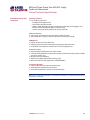
Content
Technical Specifications
Technical Specifications................................................................................................................................ 4
General Technical
Specifications
Shaft Loads........................................................................................................................................................ 6
Mounting Flange Loads................................................................................................................................ 7
Model Code....................................................................................................................................................... 8
Electrical Displacement Control (EDC) Options A2 (12 V)/A3 (24 V)...........................................12
Forward-Neutral-Reverse (FNR) Electric Control Options A9 (12 V)/B1 (24 V)........................14
Non Feedback Proportional Electric Control (NFPE) Options A8 (12 V) / B8 (24 V)...............16
Automotive Control (AC)............................................................................................................................18
Manual Over Ride (MOR)............................................................................................................................20
Displacement Limiter...................................................................................................................................21
Dimensions
Input Shafts.....................................................................................................................................................22
Option G4, ISO 3019-1, flange outer dia 22 mm-4 (SAE B, 13 teeth).....................................22
Option G5, ISO 3019-1, flange outer dia 25 mm-4 (SAE B-B, 15 teeth).................................22
Option G1, ISO 3019-1, outer dia 32 mm-4 (SAE B, 14 teeth)...................................................23
Option F2, ISO 3019-1, Code 25-3, Diameter 25.4 taper 1:8,
without key and no through-hole in the end of the shaft........................................................24
Auxiliary Mounting Pads.............................................................................................................................25
Option H2, ISO 3019-1, flange 82-2 (SAE A, 9 teeth)...................................................................25
Option H1, ISO 3019-1, flange 82-2 (SAE A, 11 teeth) ...............................................................26
Option H3, ISO 3019-1, flange 101-2 (SAE B, 13 teeth)...............................................................27
Option H5, ISO 3019-1, flange 101-2 (SAE B-B, 15 teeth)..........................................................28
Charge Pump
Charge Pump..................................................................................................................................................29
Installation Drawings
Port Description.............................................................................................................................................30
Dimensions......................................................................................................................................................32
Twin port, ORB, remote filter..........................................................................................................32
Controls.......................................................................................................................................................35
Electric Displacement Control (EDC), option A2 (12 V) / A3 (24 V).................................35
Electric Displacement Control (EDC) with manual override, option A4 (12 V) / A5 (24 V)........ 35
Forward-Neutral-Reverse (FNR) with manual override, option A9 (12 V) B1 (24 V) ................... 36
Non Feedback Proportional Electric Control (NFPE) with manual override,
option A8 (12 V) B8 (24V).................................................................................................................................. 36
Automotive control (AC) with manual override, option A7 (12 V)/C2 (24 V)................37
Displacement limiters............................................................................................................................38
Displacement limiter, option B and D .......................................................................................38
Twin port, code 62 metric 4 bold FLG, option D6, D8, F2, and F3...................................39
Suction filtration, option L .............................................................................................................40
Remote full flow charge pressure filtration, option P for end cap option F ................41
External full flow charge pressure filtration, option E . ........................................................42
Speed and Temperature Sensor, option H for mounting flange option K ...................43
11063344 • Rev EA • Dec 2012
3
H1 Axial Piston Pump, Size 045/053, Single
Technical Information
Technical Specifications
Technical Specifications
For definitions of the following specifications, see Basic Information 11062168, Operating
parameters.
General specifications
Design
Direction of rotation
Pipe connections
Recommended
installation position
Auxiliary cavity pressure
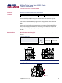
Axial piston pump of cradle swashplate design with variable displacement
Clockwise, counterclockwise
Main pressure ports: ISO split flange boss
Remaining ports: SAE straight thread O-ring boss
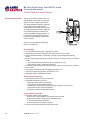
Pump installation position is discretionary, however the recommended control
position is on the top or at the side, with the top position preferred. If the pump
is installed with the control at the bottom, flushing flow must be provided
through port M14 located on the EDC, FNR and NFPE control. Vertical input
shaft installation is acceptable. If input shaft is at the top 1 bar case pressure
must be maintained during operation.
The housing must always be filled with hydraulic fluid.
Recommended mounting for a multiple pump stack is to arrange the highest
power flow towards the input source.
Consult Sauer-Danfoss for nonconformance to these guidelines.
Will be inlet pressure with internal charge pump. For reference see operating
parameter on next page. Will be case pressure with external charge supply.
Please verify mating pump shaft seal capability.
T000 126E
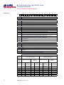
Technical data
Feature
Unit
Size 045
Size 053
[in3]
45.0
[2.75]
53.8
[3.28]
Displacement
cm3
Flow at rated (continuous) speed
l/min [US gal/min]
153
[40]
183
[48]
Torque at maximum displacement
[lbf•in/
N•m/bar
0.72
[437.7]
0.86
[522.03]
(theoretical)
1000psi]
Mass moment of inertia of rotating
[slug•ft2]
0.00465 [0.00343]
0.00458
[0.00338]
kg•m2
components
Mass [weight] dry (without charge
pump or auxiliary mounting
kg
[lb]
41.0
[90.0]
flange)
Oil volume
liter
[US gal]
1.3
[0.34]
ISO 3019-1 flange 101-2 (SAE B)
Mounting flange
Special bolt diameter. See installation drawings.
ISO 3019-1, outer dia 22 mm - 4 (SAE B, 13 teeth)
Input shaft outer diameter,
ISO 3019-1, outer dia 25 mm - 4 (SAE B-B, 15 teeth)
splines and tapered shafts
ISO 3019-1, outer dia 32 mm - 4 (SAE-B, 14 teeth)
Conical keyed shaft end similar to ISO 3019-1 code 25-3, taper 1:8
ISO 3019-1, flange 82 - 2, outer dia 16 mm - 4 (SAE A, 9 teeth)
Auxiliary mounting flange with metric
ISO 3019-1, flange 82 - 2, outer dia 19 mm - 4 (SAE A, 11 teeth)
fasteners, shaft outer diameter and
ISO 3019-1, flange 101 - 2, outer dia 22 mm - 4 (SAE B, 13 teeth)
splines
ISO 3019-1, flange 101 - 2, outer dia 25 mm - 4 (SAE B-B, 15 teeth)
Suction ports
ISO 11926-1 – 1 5/16 -12 (SAE O-ring boss)
∅19.0 - 450 bar split flange boss per ISO 6162, M10x1.5
Main port configuration
ISO 11926-1 – 1 5/16 -12 (SAE O-ring boss)
Case drain ports L1, L2
ISO 11926-1 – 1 1/16 -12 (SAE O-ring boss)
Other ports
SAE O-ring boss. See installation drawings at the back of this manual.
Customer interface threads
Metric fasteners
T301 001E
4
11063344 • Rev EA • Dec 2012
H1 Axial Piston Pump, Size 045/053, Single
Technical Information
Technical Specifications
Technical Specifications
(continued)
For definitions of the following specifications, see Basic Information 11062168, Operating
parameters.
Operating parameters
Feature
Input speed
System pressure
Charge pressure
Control pressure
Charge pump inlet pressure
Case pressure
Lip seal external pressure
Unit
Minimum for internal charge supply
at minimum charge pressure. Performance (pressure and displacement)
may be limited due to limited control
pressure
Minimum for external charge supply
at minimum charge pressure. Full
performance (pressure and displacemin-1 (rpm)
ment) possible at minimum charge
and control pressure supply.
Minimum for full performance (pressure and displacement) for internal
charge supply at minimum charge
and control pressure
Rated
Maximum
Maximum working pressure
Maximum pressure
bar
[psi]
Maximum low loop
Minimum low loop pressure
Minimum
bar
[psi]
Maximum
Minimum (at corner power for EDC
and FNR)
bar
[psi]
Minimum (at corner power for NFPE)
Maximum
Rated
bar (absolute) [in Hg vacuum]
Minimum (cold start)
Maximum
bar
[psi]
Rated
bar
[psi]
Maximum
Maximum
bar
[psi]
Size 045
Size 053
500
500
1175
1250
3400
3500
420
450
[6090]
[6525]
45
10
16
35
380
400
[650]
[150]
[232]
[508]
21.5
[312]
24
40
0.7
0.2
4.0
3.0
5.0
0.4
[348]
[580]
[9]
[24]
[58]
[44]
[73]
[5.8]
T000 171E
Fluid specifications
Feature
Viscosity
Temperature
range 2)
Filtration
(recommended
minimum)
[5510]
[5800]
Unit
Intermittent 1)
Minimum
Recommended range
Maximum
Minimum (cold start) 3)
Recommended range
Rated
Maximum intermittent 1)
Cleanliness per ISO 4406
Efficiency (charge pressure filtration)
Efficiency (suction and return line filtration)
mm2/s
[SUS]
°C
[°F]
β-ratio
Recommended inlet screen mesh size
µm
1)
Intermittent = Short term t < 1min per incident and not exceeding 2 % of duty cycle based load-life
2)
At the hottest point, normally case drain port
3)
Cold start = Short term t < 3min, p ≤ 50 bar [725 psi], n ≤ 1000 min-1(rpm)
11063344 • Rev EA • Dec 2012
5
7
12-80
1600
-40
60-85
104
115
[42]
[49]
[66-370]
[7500]
[-40]
[140-185]
[220]
[240]
22/18/13
β15-20 = 75 (β10 ≥ 10)
β35-45 = 75 (β10 ≥ 2)
100 – 125
T000 129E
5
H1 Axial Piston Pump, Size 045/053, Single
Technical Information
General Technical Specifications
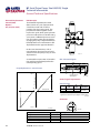
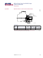
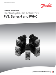
Shaft Loads
External radial shaft loads
H1 pumps are designed with bearings that can accept some external radial loads.
The external radial shaft load limits are a function of the load position and orientation,
and the operating conditions of the unit. External radial shaft loads impact lifetime.
For lifetime calculations please contact Sauer-Danfoss representative.
The maximum allowable radial load (Re) is based on the maximum external moment
(Me) and the distance (L) from the mounting flange to the load. It may be determined
using the following table and formula.
Re = Me / L
Radial load position
0° Re
L
Re
90° Re
270° Re
Me
Me = Shaft moment
L = Flange distance
Re = External force to the shaft
180° Re
P301 168
Thrust loads should be avoided. Contact factory in the event thrust loads are anticipated.
6
11063344 • Rev EA • Dec 2012
H1 Axial Piston Pump, Size 045/053, Single
Technical Information
General Technical Specifications
Shaft Loads
(continued)
Maximum external shaft load based on shaft deflection
Unit
External radial moment – Me
Nm
Size 045/053
[lbf•in]
TDB
[TBD]
All external shaft loads affect bearing life. In applications with external shaft loads,
minimize the impact by positioning the load at 0° or 180° as shown in the figure.
T000 174E
Sauer-Danfoss recommends clamp-type couplings for applications with radial shaft
loads.
Contact your Sauer-Danfoss representative for an evaluation of unit bearing life if you
have continuously applied external loads exceeding 25 % of the maximum allowable
radial load (Re) or the pump swashplate is positioned on one side of center all or most of
the time.
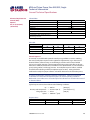
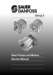
Mounting Flange
Loads
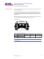
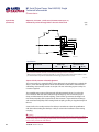
H1 single pump front flange load
The moments shown below apply for control orientation top or side (see table and
figures).j
Mounting flange load
Size 045/053
Control orientation
Unit
Rated moment – MR
Shock load moment – MS
Nm
[lbf•in]
Control on top
Control on side
2020
[17 880]
1300
[11 510]
4110
[36 380]
2930
[25 935]
T000 175E
Control on top
Control on side
P301 214
For calculation details refer to H1 Pump Basic Information Manual 11062168, section
Mounting Flange Loads.
MR
MS
P301 213
11063344 • Rev EA • Dec 2012
7
H1 Axial Piston Pump, Size 045/053, Single
Technical Information
General Technical Specifications
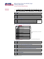
Model Code
A B
H1 P
D
F
E
G
H
J
K
M
N
S T
V
W
X
Y
A
Displacement
045
053
A
Rotation
L
R
B
A8
B8
A7
C2
Orifices, 0.8 mm in servo supply 1 and 2, recommended for propel applications
Orifices, 1.3 mm in servo supply 1 and 2 (Standard), recommended for propel applications
No orifice, recommended for non-propel applications
Displacement limiters
N
C
G
Electric Displacement Control (EDC) 12V, Deutsch connector
Electric Displacement Control (EDC) 24V, Deutsch connector
Electric Displacement Control (EDC) 12V, Deutsch connector, Manual override
Electric Displacement Control (EDC) 24V, Deutsch connector, Manual override
Forward-Neutral-Reverse (FNR) 12V, Deutsch connector, Manual override
Forward-Neutral-Reverse (FNR) 24V, Deutsch connector, Manual override
Non Feedback Proportional Electric (NFPE) 12V, Deutsch connector, Manual override
(align with option E: Displacement Limiters & option W: Special Hardware)
Non Feedback Proportional Electric (NFPE) 24V, Deutsch connector, Manual override
(align with option E: Displacement Limiters & option W: Special Hardware)
AC-1 (Automotive), 12V, Manual Override (align with option E: Displacement Limiters & option W:
Special Hardware)
AC-1 (Automotive), 24V, Manual Override (align with option E: Displacement Limiters & option W:
Special Hardware)
Orifices
C1
C2
C3
E
Revision code
Control
A2
A3
A4
A5
A9
B1
F
Left hand (counter clockwise)
Right hand (clockwise)
Product Version
A
D
45 cm³ [2.75 in³]
53.8 cm³ [3.28 in³]
B
D
None
No limiters, with nested springs (required for NFPE) (align with option Y: Settings for adjustment, if
applicable)
Adjustable externally (align with option Y: Settings for adjustment, if applicable)
Adjustable externally with nested springs, required for NFPE
Endcap options
Twin port
High
pressure
ports
Match
with below
options
(M+N)
ISO 11 926 O-ring ports
With pressure limiter
Without pressure
limiter
(HPRV only)
ISO 6162 split flange ports
With pressure limiter
Without pressure
limiter
(HPRV only)
Remote and
Remote or
Remote and
Remote or
Match
external
external
external
external
Suction
Suction
Suction
Suction
with below filtration charge supply filtration charge supply filtration charge supply filtration charge supply
options (T)
for full charge
for full charge
for full charge
for full charge
flow filtration
flow filtration
flow filtration
flow filtration
D6
X
D8
X
E5
X
E6
X
E9
X
F1
X
F2
X
F3
X
8
11063344 • Rev EA • Dec 2012
H1 Axial Piston Pump, Size 045/053, Single
Technical Information
General Technical Specifications
Model Code
(continued)
A B
D
F
E
H1 P
H
K
M
N
S T
V
W
X
Y
NNN NNN
ISO 3019-1, flange 101-2 (SAE B)
Input shaft
ISO 3019-1, outer dia 22 mm - 4 (SAE B, 13 teeth splined shaft 16/32 pitch)
ISO 3019-1, outer dia 25 mm - 4 (SAE B-B, 15 teeth splined shaft 16/32 pitch)
ISO 3019-1, outer dia 32 mm - 4 (SAE B, 14 teeth splined shaft 12/24 pitch)
Conical keyed shaft end similar to ISO 3019-1 code 25-3, taper 1:8 (key not supplied with pump)
Auxiliary mounting pad
NN
H2
H1
H3
H5
M
N
J
Mounting
G4
G5
G1
F2
K
H
F
F
J
G
None
ISO 3019-1, flange 82 - 2, outer dia 16 mm - 4 (SAE A, 9 teeth 16/32 coupling)
ISO 3019-1, flange 82 - 2, outer dia 19 mm - 4 (SAE A, 11 teeth 16/32 coupling)
ISO 3019-1, flange 101 - 2, outer dia 22 mm - 4 (SAE B, 13 teeth 16/32 coupling)
ISO 3019-1, flange 101 - 2, outer dia 25 mm - 4 (SAE B-B, 15 teeth 16/32 coupling)
Shipping cover
Overpressure protection type and setting side “A” **
Overpressure protection type and setting side “B” **
** Pressure protection type must be the same for side “A” and “B”
High pressure relief valve + pressure
limiters with bypass
High pressure relief valve only with bypass
K
(no pressure limiters)
L18 K18 180 bar [2610 psi]
L20 K20 200 bar [2900 psi]
L23 K23 230 bar [3336 psi]
Use the selection for ports “A” and “B”
L25 K25 250 bar [3630 psi]
L28 K28 280 bar [4061 psi]
L30 K30 300 bar [4350 psi]
L33 K33 330 bar [4786 psi]
L35 K35 350 bar [5080 psi]
L38 K38 380 bar [5510 psi]
L40 K40 400 bar [5800 psi] (45 cm3 only)
L42 K42 420 bar [6090 psi] (45 cm3 only)
Contact factory for pressures not shown or for applied pressure above maximum working pressure
(see System Pressure page 5)
L
S
Charge pump
B
N
T
Filtration options (align with option G: Endcap selection)
L
P
E
V
Suction filtration (see basic drawings)
Remote full charge flow filtration (see endcap drawings)
External charge flow filtation (see endcap drawings), (align with option S: Charge pump, option N)
Charge pressure relief setting (contact factory for pressure not shown)
20
24
W
12 cm³/rev [0.73 in³/rev]
No charge pump, external charge supply, (align with Option T: Filtration Options, option E)
20 bar [290 psi]
24 bar [348 psi]
Special hardware features
PN
P1
None
NFPE valve plate (align with option D: Control Selection and option E: Displacement Limiters)
11063344 • Rev EA • Dec 2012
9
H1 Axial Piston Pump, Size 045/053, Single
Technical Information
General Technical Specifications
Model Code
(continued)
A B
X
F
Y
E
G
H
J
F
K
M
N
S T
V
W
X
Black paint and Sauer-Danfoss nametag
Special settings
NNN
D3F
D4F
D3H
D4H
None
AC1-control, System F: Functional basis, Motor Speed Sensor, CAN J1939 in/out without
Customer Files, 12V
AC1-control, System F: Functional basis, Motor Speed Sensor, CAN J1939 in/out without
Customer Files, 24V
AC1-control, System H: Functional basis, Motor Speed Sensor, CAN J1939 out, SIL2 certifiable
without Customer Files, 12V
AC1-control, System H: Functional basis, Motor Speed Sensor, CAN J1939 out, SIL2 certifiable
without Customer Files, 24V
11063344 • Rev EA • Dec 2012
Y
NNN NNN
Paint and nametag
NNN
10
D
H1 P
H1 Axial Piston Pump, Size 045/053, Single
Technical Information
Notes
Notes
11063344 • Rev EA • Dec 2012
11
H1 Axial Piston Pump, Size 045/053, Single
Technical Information
General Technical Specifications
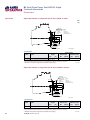
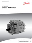
Electrical Displacement
Control (EDC)
Options
A2 (12 V)/A3 (24 V)
EDC Principle
The Electrical Displacement Control
(EDC) consists of a pair of proportional
solenoids on each side of a threeposition, four-way porting spool. The
proportional solenoid applies a force
input to the spool, which ports hydraulic
pressure to either side of a double acting
servo piston. Differential pressure across
the servo piston rotates the swashplate,
changing the pump‘s displacement from
full displacement in one direction to full
displacement in the opposite direction.
Under some circumstances, such as
contamination, the control spool could
stick and cause the pump to stay at some
displacement.
A serviceable 125 μm screen is located in
the supply line immediately before the
control porting spool.
M14
C2
F00B
Displacement
100 %
-a
EDC-Schematic diagram
C1
Pump displacement vs. control current
-b
P003 191
F00A
Feedback from
Swash plate
T
P
P003 478E
Control signal requirements
Control current
a*
b
Pin
mA
mA
connections
12 V
640
1640
any order
24 V
330
820
* Factory test current, for vehicle movement or
application actuation expect higher or lower value.
Voltage
Current mA
"0"
a
b
T000133E
Connector
100 %
1
2
P003 479E
P003 480
Description
Mating connector
Wedge lock
Socket contact (16 and 18 AWG)
Sauer-Danfoss mating connector kit
Quantity
1
1
2
1
Ordering number
Deutsch® DT06-2S
Deutsch® W2S
Deutsch® 0462-201-16141
K29657
T000 134E
12
11063344 • Rev EA • Dec 2012
H1 Axial Piston Pump, Size 045/053, Single
Technical Information
General Technical Specifications
Electrical Displacement
Control (EDC)
Options
A2 (12 V)/A3 (24 V)
(continued)
Solenoid data
Voltage
Maximum current
Coil resistance @ 20 °C [70 °F]
Coil resistance @ 80 °C [176 °F]
PWM Range
PWM Frequency (preferred)*
Inductance
IP Rating (IEC 60 529) + DIN 40 050, part 9
IP Rating (IEC 60 529) + DIN 40 050, part 9
with mating connector
* PWM signal required for optimum control performance.
12V
1800 mA
3.66 Ω
4.52Ω
24V
920 mA
14.20 Ω
17.52Ω
70-200 Hz
100 Hz
33 mH
140 mH
IP 67
IP 69K
T000 135E
Flow table
Shaft rotation
CW
Coil energized*
C2
Port A
in
Port B
out
Servo port pressurized
M5
* For coil location see installation drawings.
CCW
C1
out
in
M4
C2
out
in
M5
C1
in
out
M4
T000 136E
Control response
H1 controls are available with optional control passage orifices to assist in matching
the rate of swashplate response to the application requirements (e.g. in the event of
electrical failure). Software ramp or rate limiting should be used to control vehicle
response in normal operation. The time required for the pump output flow to change
from zero to full flow (acceleration) or full flow to zero (deceleration) is a net function of
spool porting, orifices, and charge pressure. A swashplate response table is available
for each frame indicating available swashplate response times. Testing should be
conducted to verify the proper software and orifice selection for the desired response.
H1 pumps are limited in mechanical orificing combinations. Software is envisioned
as the means to control the swashplate response in normal operating conditions.
Mechanical servo orifices are to be used only for fail-safe return to neutral in the event of
an electrical failure.
Typical response times shown below at the following conditions:
∆p
Viscosity and temperature
Charge pressure
Speed
=
=
=
=
250 bar
30 mm2/s (50 °C)
20 bar
1800 min-1 (rpm)
[3626 psi]
[141 SUS (122 °F)]
[290 psi]
Response times
Stroking direction
Neutral to full flow
Full flow to neutral
0.8 mm [0.03 in] Orifice 1.3 mm [0.05 in] Orifice
1.7 s
0.9 s
1.1 s
0.6 s
No orifice
0.5 s
0.3 s
T000 177E
11063344 • Rev EA • Dec 2012
13
H1 Axial Piston Pump, Size 045/053, Single
Technical Information
General Technical Specifications
Forward-Neutral-Reverse
(FNR) Electric Control
Options
A9 (12 V)/B1 (24 V)
The 3-Position (F-N-R) control uses an
electric input signal to switch the pump
to a full stroke position.
Under some circumstances, such as
contamination, the control spool could
stick and cause the pump to stay at some
displacement.
A serviceable 125 μm screen is located in
the supply line immediately before the
control porting spool.
P003 193
Pump displacement vs. electrical signal
3-Position electric control,
hydraulic schematic
M14
100 %
Displacement
C1
“0“
C2
F00B
T
F00A
P
P003 189
Voltage VDC
Control current
Voltage
12 V
24 V
Min. current to
stroke pump
mA
750
380
Pin
connections
any order
T000 138E
100 %
P003 190E
Solenoid connector
1
2
P003 480
Description
Mating connector
Wedge lock
Socket contact (16 and 18 AWG)
Sauer-Danfoss mating connector kit
Quantity
1
1
2
1
Ordering number
Deutsch® DT06-2S
Deutsch® W2S
Deutsch® 0462-201-16141
K29657
T000 134E
14
11063344 • Rev EA • Dec 2012
H1 Axial Piston Pump, Size 045/053, Single
Technical Information
General Technical Specifications
Forward-Neutral-Reverse
(FNR) Electric Control
Options
A9 (12 V)/B1 (24 V)
(continued)
Solenoid data
Voltage
Minimum supply voltage
Maximum supply voltage (continuous)
Maximum current
Nominal coil resistance @ 20 °C [70 °F]
PWM Range
PWM Frequency (preferred)*
IP Rating (IEC 60 529) + DIN 40 050, part 9
IP Rating (IEC 60 529) + DIN 40 050, part 9
with mating connector
* PWM signal required for optimum control performance.
12 V
9.5 Vdc
14.6 Vdc
1050 mA
8.4 Ω
24 V
19.0 Vdc
27.0 Vdc
500 mA
34.5 Ω
70-200 Hz
100 Hz
IP 67
IP 69K
T000 139E
Pump output flow direction vs. control signal
Shaft rotation
CW
Coil energized*
C1
Port A
in
Port B
out
Servo port pressurized
M5
* For coil location see installation drawings.
CCW
C2
out
in
M4
C1
out
in
M5
C2
in
out
M4
T000 140E
Control response
H1 controls are available with optional control passage orifices to assist in matching
the rate of swashplate response to the application requirements (e.g. in the event of
electrical failure). Software ramp or rate limiting should be used to control vehicle
response in normal operation. The time required for the pump output flow to change
from zero to full flow (acceleration) or full flow to zero (deceleration) is a net function of
spool porting, orifices, and charge pressure. A swashplate response table is available
for each frame indicating available swashplate response times. Testing should be
conducted to verify the proper software and orifice selection for the desired response.
H1 pumps are limited in mechanical orificing combinations. Software is envisioned
as the means to control the swashplate response in normal operating conditions.
Mechanical servo orifices are to be used only for fail-safe return to neutral in the event of
an electrical failure.
Typical response times shown below at the following conditions:
∆p
Viscosity and temperature
Charge pressure
Speed
=
=
=
=
250 bar
30 mm2/s (50 °C)
20 bar
1800 min-1 (rpm)
[3626 psi]
[141 SUS (122 °F)]
[290 psi]
Response times
Stroking direction
Neutral to full flow
Full flow to neutral
0.8 mm [0.03 in] Orifice 1.3 mm [0.05 in] Orifice
1.8 s
0.9 s
1.6 s
0.8 s
No orifice
0.5 s
0.4 s
T000 179E
11063344 • Rev EA • Dec 2012
15
H1 Axial Piston Pump, Size 045/053, Single
Technical Information
General Technical Specifications
Non Feedback
Proportional Electric
Control (NFPE)
Options A8 (12 V) /
B8 (24 V)
The Non Feedback Proportional Electric
(NFPE) control is an electrical automotive
control in which an electrical input
signal activates one of two proportional
solenoids that port charge pressure to
either side of the pump servo cylinder.
The NFPE control has no mechanical
feedback mechanism.
The pump displacement is proportional
to the solenoid signal current, but it also
depends upon pump input speed and
system pressure. This characteristic also
provides a power limiting function by
reducing the pump swashplate angle
as system pressure increases. A typical
response characteristic is shown in the
accompanying graph.
Under some circumstances, such as
contamination, the control spool could
stick and cause the pump to stay at some
displacement.
A serviceable 125 μm screen is located in
the supply line immediately before the
control porting spool.
P003 192
NFPE Schematic
M14
C1
C2
F00A
F00B
T
Pump displacement vs. input signal
100 %
Control signal requirements
NFPE control
r
Control current
bar
=0
∆p
300
bar
∆p
=
"0"
a
= 30
∆p
b
a*
mA
710
360
715
365
b
c Pin
mA mA connections
1135 1380
585 675
any order
1140 1495
570 720
* Factory test current, for vehicle movement or application actuation expect higher or lower value.
c
T301 002E
Displacement
a
b
Size
Voltage
(cm3)
12 V
45
24 V
12 V
53
24 V
0 ba
r
0 ba
∆p
=
Signal Current
mA(DC)
c
P
P003 188
Connector
1
100 %
Description
Mating connector
Wedge lock
Socket contact (16 and 18 AWG)
Sauer-Danfoss mating connector kit
2
P003 187E
Quantity
1
1
2
1
P003 480
Ordering number
Deutsch® DT06-2S
Deutsch® W2S
Deutsch® 0462-201-16141
K29657
T000 134E
16
11063344 • Rev EA • Dec 2012
H1 Axial Piston Pump, Size 045/053, Single
Technical Information
General Technical Specifications
Non Feedback
Proportional Electric
Control (NFPE)
Options A8 (12 V) /
B8 (24 V)
(continued)
Solenoid data
Voltage
Maximum current
Coil resistance @ 20 °C [70 °F]
Coil resistance @ 80 °C [176 °F]
PWM Range
PWM Frequency (preferred)*
Inductance
IP Rating (IEC 60 529) + DIN 40 050, part 9
IP Rating (IEC 60 529) + DIN 40 050, part 9
with mating connector
* PWM signal required for optimum control performance.
12V
1800 mA
3.66 Ω
4.52Ω
24V
920 mA
14.20 Ω
17.52Ω
70-200 Hz
100 Hz
33 mH
140 mH
IP 67
IP 69K
T000 135E
Pump output flow direction vs. control signal
Shaft rotation
CW
Coil energized*
C1
Port A
in
Port B
out
Servo port pressurized
M5
* For coil location see installation drawings.
CCW
C2
out
in
M4
C1
out
in
M5
C2
in
out
M4
T000 140E
Control response
H1 controls are available with optional control passage orifices to assist in matching
the rate of swashplate response to the application requirements (e.g. in the event of
electrical failure). Software ramp or rate limiting should be used to control vehicle
response in normal operation. The time required for the pump output flow to change
from zero to full flow (acceleration) or full flow to zero (deceleration) is a net function of
spool porting, orifices, and charge pressure. A swashplate response table is available
for each frame indicating available swashplate response times. Testing should be
conducted to verify the proper software and orifice selection for the desired response.
H1 pumps are limited in mechanical orificing combinations. Software is envisioned
as the means to control the swashplate response in normal operating conditions.
Mechanical servo orifices are to be used only for fail-safe return to neutral in the event of
an electrical failure.
Typical response times shown below at the following conditions:
∆p
Viscosity and temperature
Charge pressure
Speed
=
=
=
=
250 bar
30 mm2/s (50 °C)
20 bar
1800 min-1 (rpm)
[3626 psi]
[141 SUS (122 °F)]
[290 psi]
Response times
Stroking direction
Neutral to full flow
Full flow to neutral
0.8 mm [0.03 in] Orifice 1.3 mm [0.05 in] Orifice
2.2 s
1.1 s
1.3 s
0.7 s
No orifice
0.7 s
0.3 s
T301 004E
11063344 • Rev EA • Dec 2012
17
H1 Axial Piston Pump, Size 045/053, Single
Technical Information
General Technical Specifications
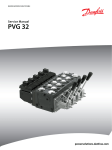
Automotive Control (AC)
CC1
CC2
The H1 AC Control offers the following
features and functions:
WARRANTY VOID IF REMOVED
CC3
CAN PPC PSC PPU
The H1 Automotive Control (H1 AC) is an
electric NFPE Control with an integrated
Microcontroller, installed on the pump.
The integrated Microcontroller enhanced
control performance with a flexible,
configurable control scheme for an entire
single path propel transmission. With the
pre-installed application software and
easily changeable control parameters, it
is possible to tailor the vehicle’s driving
behavior to the individual requirements
of the customer.
P003 544
Driving Profiles
• Four selectable system modes, selectable via switch.
• Independent curves and settings for forward and reverse (4 x 2 curves).
• Switch selectable between automotive and engine speed independent driving
modes.
• Engine speed independent drive modes for sweepers, snow blowers (non-automotive
mode).
–– Load independent drive modes for off road applications (nonautomotive for rollers and forestry machines).
• Load independent swash plate control via pump swash plate angle sensor to achieve
EDC behavior
• Creep speed mode (slow shunting, digging operation, etc.)
• Constant speed mode (sweepers, snow-blowers, etc.)
• Integrated vehicle speed limiter function.
Advanced Control Functions
• Inch function without separate control valve.
• Integrated temperature sensor for:
–– Hydraulic systems overheat protection.
–– Low temperatures pump flow limitation.
–– Compensation of oil viscosity changes if using (radial piston motors, etc.).
–– Configurable engine anti stall protection.
–– Engine over speed protection while inching.
Integrated Motor Controller
• Integrated electric motor control for:
–– Proportional, variable PCOR or two position motor controls.
–– Brake pressure defeat, depending on the FNR position
or the real vehicle driving direction.
–– Initial breakaway motor torque override.
• Separate over speed protection for the hydro motor.
18
11063344 • Rev EA • Dec 2012
H1 Axial Piston Pump, Size 045/053, Single
Technical Information
General Technical Specifications
Automotive control (AC)
(continued)
Auxiliary Functions
• Four auxiliary outputs for :
–– Intelligent brake light control.
–– Automatic park brake function.
–– Vehicle speed dependent output to activate (load stabilizer, warning lights, etc.).
–– Reverse buzzer controlled by FNR or reverse driving.
–– System status lamp (fault detection for pump solenoids). Economic Features
• Technology and enabler for economic driving and fuel savings.
• Easy combination options to other components of the PLUS+1 Family.
CAN Options
• Engine remote control via CAN J1939.
• Integrated signal converter (analog driving pedal into CAN signal, etc.).
• Compatible to all CAN J1939 components on market (displays, etc.).
Functional Safety
• External Safety Certification for SIL-2 (IEC 61508).
• Safety controlled Vehicle Start-Protection (engine speed check, battery check and FNR
must be in neutral, etc.).
• Operator presence detection.
• Vehicle speed dependent direction change lock.
• Brake test mode for roller applications to fulfill EN500-4.
Installation Features
• Factory calibration for hysteresis compensation.
• Starting current adjustment in the factory
• Pre-installed application software and parameter files
Refer to the “Technical Information – H1 Automotive Control” L1223856 for details about
installation and wiring.
11063344 • Rev EA • Dec 2012
19
H1 Axial Piston Pump, Size 045/053, Single
Technical Information
General Technical Specifications
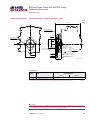
Manual Over Ride (MOR)
All controls are available with a Manual Over Ride (MOR) either standard or as an option
for temporary actuation of the control to aid in diagnostics.
Forward-Neutral-Reverse (FNR) and Non Feedback Proportional Electric (NFPE) controls
are always supplied with MOR functionality.
Unintended MOR operation will cause the pump to go into stroke. The vehicle or device
must always be in a „safe“ condition (i.e. vehicle lifted off the ground) when using the
MOR function. The MOR plunger has a 4 mm diameter and must be manually depressed
to be engaged. Depressing the plunger mechanically moves the control spool which
allows the pump to go on stroke. The MOR should be engaged anticipating a full stroke
response from the pump.
Warning
An o-ring seal is used to seal the MOR plunger where initial actuation of the function will
require a force of 45 N to engage the plunger. Additional actuations typically require
less force to engage the MOR plunger. Proportional control of the pump using the MOR
should not be expected.
Refer to control flowtable for the relationship of solenoid to direction of flow.
P003 204
MOR-Schematic diagram (EDC shown)
M14
C1
C2
F00B
F00A
Feedback from
Swash plate
20
11063344 • Rev EA • Dec 2012
T
P
P003 205E
H1 Axial Piston Pump, Size 045/053, Single
Technical Information
General Technical Specifications
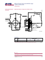
Displacement Limiter
H1 pumps are designed with optional mechanical displacement (stroke) limiters factory
set to max. displacement.
The maximum displacement of the pump can be set independently for forward and
reverse using the two adjustment screws to mechanically limit the travel of the servo
piston down to 50 % displacement. Adjustment procedures are found in the H1 pumps
Service Manual.
Adjustments under operating conditions may cause leakage. The adjustment screw can
be completely removed from the threaded bore if backed out to far.
Displacement limiter
P003 266
Displacement change (approximately)
Size
045
053
1 Turn of displacement
limiter screw
[0.31 in3]
5.1 cm3
3
6.0 cm
[0.37 in3]
Internal
wrench size
External
wrench size
4 mm
13 mm
Torque for external
hex seal lock nut
23 Nm
[204 lbf•in]
T000 181E
For more information refer to H1 pumps Service Manual 520L958, section Displacement
Limiter Adjustment.
11063344 • Rev EA • Dec 2012
21
H1 Axial Piston Pump, Size 045/053, Single
Technical Information
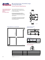
Dimensions
Option G4, ISO 3019-1, flange outer dia 22 mm-4 (SAE B, 13 teeth)
Spline data
Number of teeth : 13
Pitch fraction
: 16/32
Pressure angle : 30°
Pitch ∅
: ∅20.6375
Type of fit
: fillet root side
Per
: ansi b92.1b class 6e
∅74.3 MIN
∅18.5
±0.12
33 ±0.68
16. 5 ±0.15
Paint free
8 ±0.8
mm
[in]
∅22.085
±0.09
Input Shafts
Mating coupling
Must not protrude
Beyond this point
Mounting flange
Flange 101-2
Per ISO 3019-1 (SAE B)
P700 33 266
Specifications
Option
Spline
Min active spline
length2
Torque rating1
Rated torque
Maximum torque
Nm
[lbf•in]
Nm
[lbf•in]
180
[1600]
222
[1970]
mm
[in]
G4
13 teeth, 16/32 pitch
16.5
[0.65]
1)
For definitions of maximum and rated torque values, refer to:
Basic Information Manual 11062168, section Shaft Torque Ratings and Spline Lubrication.
2)
Minimum active spline length for the specified torque ratings.
T301 005E
Option G5, ISO 3019-1, flange outer dia 25 mm-4 (SAE B-B, 15 teeth)
Spline data
Number of teeth : 15
Pitch fraction
: 16/32
Pressure angle : 30°
Pitch ∅
: ∅23.813
Type of fit
: fillet root side
Per
: ansi b92.1b class 6e
8 ±0.8
∅74.3 Min
22 ±0.15
Paint free
∅25.23 ±0.09
∅21.98 ±0.12
38 ±0.68
Mating coupling
Must not protrude
Beyond this point
Mounting flange
Flange 101-2
Per ISO 3019-1 (SAE B)
P700 33 267
Specifications
Option
Spline
Min active spline
length2
Torque rating1
Rated torque
Maximum torque
Nm
[lbf•in]
Nm
[lbf•in]
277
[2450]
370
[3270]
mm
[in]
G5
15 teeth, 16/32 pitch
22.0
[0.866]
1)
For definitions of maximum and rated torque values, refer to:
Basic Information Manual 11062168, section Shaft Torque Ratings and Spline Lubrication.
2)
Minimum active spline length for the specified torque ratings.
22
11063344 • Rev EA • Dec 2012
T000 183E
H1 Axial Piston Pump, Size 045/053, Single
Technical Information
Dimensions
Option G1, ISO 3019-1, outer dia 32 mm-4 (SAE B, 14 teeth)
mm
[in]
Spline data
Number of teeth : 14
Pitch fraction
: 12/24
Pressure angle : 30°
Pitch ∅
: ∅29.633
Type of fit
: fillet root side
Per
: ANSI B92.1b CLASS 6e
30.6 ±0.15
Paint free
8 ±0.8
Mating coupling
Must not protrude
Beyond this point
Mounting flange
Flange 101-2 (SAE B)
Per ISO 3019-1
∅31.58 ±0.09
∅74.3 Min
48 ±0.68
∅25.72 ±0.12
Input Shafts
P700 33 265-45
Specifications
Option
Spline
Min active spline
length2
Torque rating1
Rated torque
Maximum torque
Nm
[lbf•in]
Nm
[lbf•in]
534
[4720]
592
[5240]
mm
[in]
G1
14 teeth, 12/24 pitch
30.6
[1.205]
1)
For definitions of maximum and rated torque values, refer to:
Basic Information Manual 11062168, section Shaft Torque Ratings and Spline Lubrication.
2)
Minimum active spline length for the specified torque ratings.
11063344 • Rev EA • Dec 2012
T000 182E
23
H1 Axial Piston Pump, Size 045/053, Single
Technical Information
Dimensions
Input Shafts
(continued)
Option F2, ISO 3019-1, Code 25-3, Diameter 25.4 taper 1:8,
without key and no through-hole in the end of the shaft
mm
[in]
63.14 ±1.01
36.17 ±0.76
∅74.3 Min
.750-16UNF-2A THD
∅22.225 Gage
9.5 ±0.38 Gage
Taper 1:8 per SAE J501
Nominal ∅25.4mm
8 ±0.8
Paint free
Mounting flange
Flange 101-2
Per ISO 3019-1 (SAE B)
P700 33 268
Specifications
Option
Tapered shaft
Torque rating1)
Rated torque
Maximum torque
Nm
[lfb•in]
Nm
[lfb•in]
405
[3580]
540
[4780]
F2
25.4 taper without key 2)
For definitions of maximum torque values, refer to:
Basic Information Manual 11062168, section Shaft Torque Ratings and Spline Lubrication.
2)
Mating part must maintain a minimum gap width of 1.0 mm with the shaft shoulder after installation of the
part. Transmittable torque will be reduced if the minimum gap requirement is not met.
1)
T000 190E
Tapered shaft customer acknowledgement
The Sauer-Danfoss H1 tapered shaft has been designed using the industry standard ISO
3019-1, minus the through-hole in the end of the shaft. Sauer-Danfoss recommends a
self-locking nut instead of a castle nut and pin. The nut and mating square-cut key are
customer supplied.
The specified torque rating of the tapered shaft documented above is based on the
cross-sectional diameter of the shaft, through the keyway, and assumes the proper
clamp and fit between shaft and coupling. Sauer-Danfoss guarantees the design and
manufactured quality of the tapered shaft. The customer is responsible for the design
and manufactured quality of the mating female coupling and key and applied torque on
the nut.
Sauer-Danfoss has made provisions for the key in accordance to the ISO specification
with the understanding that the key is solely to assist in the installation of the mating
coupling.
CCaution
Torque must be transmitted by the taper fit between the shaft and it’s mating coupling,
not the key. Torque or loading inadvertently transmitted by the customer supplied key
may lead to premature shaft failure.
24
11063344 • Rev EA • Dec 2012
H1 Axial Piston Pump, Size 045/053, Single
Technical Information
Dimensions
Auxiliary Mounting Pads
Option H2, ISO 3019-1, flange 82-2 (SAE A, 9 teeth)
mm
[in]
239.6 ±2.5
Auxiliary mounting pad
For mating flange 82-2
Per ISO 3019-1 (SAE A)
Paint free
4x M10 x1.5-6H THD
15 min THD depth
∅82.601 +0.076
0
∅88.621 +0.13
0
R0.8 max
Spline data
Number of teeth : 9
pitch fraction
: 16/32
Pressure angle : 30°
Pitch ∅
: ∅14.288
Type of fit
: fillet root side
Per
: ANSI B92.1b CLASS 7e
O-ring seal required
Ref ∅82.22 ID x 2.62 cross section
1.956 ±0.076
2x 53.2 ±0.175
Mating shaft shoulder must
Not protrude beyond this point
8.1 ±0.25
2x 106.4 ±0.35
14.5 MIN
Shaft clearance
57.2 MIN
Shaft clearance
Mating shaft must not
Protrude beyond this point
P700 33 318-45
Specifications
Option
Spline
Torque rating1
maximum torque
Nm
H2
9 teeth, 16/32 pitch
162
1)
For definitions of maximum torque values, refer to:
Basic Information Manual 11062168, section Shaft Torque Ratings and Spline Lubrication.
[lbf•in]
[1430]
T000 150E
C Caution
Standard pad cover is installed only to retain coupling during shipping. Do not operate
pump without an auxiliary pump or running cover installed.
11063344 • Rev EA • Dec 2012
25
H1 Axial Piston Pump, Size 045/053, Single
Technical Information
Dimensions
Auxiliary Mounting Pads
(continued)
Option H1, ISO 3019-1, flange 82-2 (SAE A, 11 teeth)
mm
[in]
239.6 ±2.5
Auxiliary mounting pad
For mating flange 82-2
Per ISO 3019-1 (SAE A)
Paint free
4x M10x1.5-6H THD
15 min THD depth
∅82.601 +0.076
0
∅88.621 +0.13
0
R0.8 max
Spline data
Number of teeth : 11
Pitch fraction
: 16/32
Pressure angle : 30°
Pitch ∅
: ∅17.4625
Type of fit
: fillet root side
Per
: ANSI B92.1b CLASS 7e
O-ring seal required
Ref ∅82.22 ID x 2.62 cross section
1.956 ±0.076
2x 53.2 ±0.175
Mating shaft shoulder must
Not protrude beyond this point
8.1 ±0.25
2x 106.4 ±0.35
14.5 min
Shaft clearance
57.2 min
Shaft clearance
Mating shaft must not
Protrude beyond this point
P700 33 319-45
Specifications
Option
Spline
Torque rating1
maximum torque
Nm
H1
11 teeth, 16/32 pitch
296
1)
For definitions of maximum torque values, refer to:
Basic Information Manual 11062168, section Shaft Torque Ratings and Spline Lubrication.
[lbf•in]
[2620]
T000 151E
C Caution
Standard pad cover is installed only to retain coupling during shipping. Do not operate
pump without an auxiliary pump or running cover installed.
26
11063344 • Rev EA • Dec 2012
H1 Axial Piston Pump, Size 045/053, Single
Technical Information
Dimensions
Auxiliary Mounting Pads
(continued)
Option H3, ISO 3019-1, flange 101-2 (SAE B, 13 teeth)
mm
[in]
239.6
"A" ±2.5
±2.5
Auxiliary mounting pad
For mating flange 101-2
Per ISO 3019-1 (SAE B)
4x M 12 x1.75-6H THD
19.75 min THD depth
Note:
bolt length
greater than
19.75 mm could
result in a leak or
damage to the unit
Paint free
∅101.651 +0.076
0
∅107.823
+0.13
0
R0.8 MAX
Spline data
Number of teeth : 13
Pitch fraction
: 16/32
Pressure angle : 30°
Pitch ∅
: ∅20.638
Type of fit
: fillet root side
Per
: see
ANSItable
B92.1b CLASS 7e
O-ring seal required
Ref ∅94.92 id x 2.62 cross section
2x 73 ±0.175
Mating shaft shoulder must
Not protrude beyond this point
1.956 ±0.076
11.4 ±0.25
2x 146 ±0.35
"B" Min
14.5
Min
Shaft clearance
57.2
"C" Min
Min
Shaft clearance
Mating shaft must not
Protrude beyond this point
P700 33 320-45
Specifications
Option
Spline
Torque rating1
maximum torque
Nm
H3
13 teeth, 16/32 pitch
395
1)
For definitions of maximum torque values, refer to:
Basic Information Manual 11062168, section Shaft Torque Ratings and Spline Lubrication.
[lbf•in]
[3500]
T000 152E
C Caution
Standard pad cover is installed only to retain coupling during shipping. Do not operate
pump without an auxiliary pump or running cover installed.
11063344 • Rev EA • Dec 2012
27
H1 Axial Piston Pump, Size 045/053, Single
Technical Information
Dimensions
Auxiliary Mounting Pads
(continued)
Option H5, ISO 3019-1, flange 101-2 (SAE B-B, 15 teeth)
mm
[in]
239.6 ±2.5
Auxiliary mounting pad
For mating flange 101-2
Per ISO 3019-1 (SAE B)
Paint free
4x M12x1.75-6H THD
19.75 min THD depth
Note:
Bolt length greater than
19.75 mm could result in
a leak or damage to the unit
∅101.651 +0.076
0
∅107.823 +0.13
0
R0.8 max
Spline data
Number of teeth : 15
Pitch fraction
: 16/32
Pressure angle : 30°
Pitch ∅
: ∅23.813
Type of fit
: fillet root side
Per
: ANSI B92.1b CLASS 7e
O-ring seal required
Ref ∅94.92 id x 2.62 cross section
2x 73 ±0.175
2x 146 ±0.35
Mating shaft shoulder must
Not protrude beyond this point
1.956 ±0.076
11.4 ±0.25
14.5 min
Shaft clearance
57.2 min
Shaft clearance
Mating shaft must not
Protrude beyond this point
P700 33 321-45
Specifications
Option
Spline
Torque rating1
maximum torque
Nm
H5
15 teeth, 16/32 pitch
405
1)
For definitions of maximum torque values, refer to:
Basic Information Manual 11062168, section Shaft Torque Ratings and Spline Lubrication.
[lbf•in]
[3580]
T000 212E
C Caution
Standard pad cover is installed only to retain coupling during shipping. Do not operate
pump without an auxiliary pump or running cover installed.
28
11063344 • Rev EA • Dec 2012
H1 Axial Piston Pump, Size 045/053, Single
Technical Information
Charge Pump
Charge Pump
Charge pump sizing/selection
In most applications a general guideline is that the charge pump displacement should
be at least 10 % of the total displacement of all components in the system. Unusual
application conditions may require a more detailed review of charge flow requirements.
Please refer to BLN-9885, Selection of Drive line Components, for a detailed procedure.
System features and conditions which may invalidate the 10 % guideline include (but are
not limited to):
• Continuous operation at low input speeds (< 1500 min-1 (rpm))
• High shock loading and/or long loop lines
• High flushing flow requirements
• Multiple Low Speed High Torque motors
• High input shaft speeds
Contact your Sauer-Danfoss representative for application assistance if your application
includes any of these conditions.
Charge pump flow and power curves
Charge pressure: 20 bar [290 psi]
Viscosity and temperature: 11 mm2/s [63 SUS]
Charge pump power requirements
Charge pump flow
14
50
12
5.0
3.5
40
4.0
3
1
0
3
73
[0.
in
1
2.0
1.0
0
0
500
1000
1500
2500
2000
Speed min-1(rpm)
2.5
3.0
10
0
3.0
]
v
/re
HP
3
m
2c
20
l/min
US gal/min
30
3000
3500
4000
P003 368E
11063344 • Rev EA • Dec 2012
2.0
Kw
9
6
80 °C [180 °F]
1.5
3
12
1.0
cm
3
[0.7
3
]
rev
in /
0.5
0
0
500
1000
1500
2500
2000
-1
Speed min (rpm)
3000
3500
4000
P003 369E
29
H1 Axial Piston Pump, Size 045/053, Single
Technical Information
Installation Drawings
Control solenoid connector "C2"
Deutsch DT04-2P
To be paint free
Port Description
Case drain port "L4"
Port ISO 11926-1 - 1 1/16-12
Servo gauge port "M4"
Port ISO 11926-1 - 7/16-20
∅29 max clearance dia for fitting
System port "B"
Port ISO 11926-1 - 1 5/16-12
CCW
P700 33 051-1
Charge inlet port "S"
Port ISO 11926-1 - 1 5/16-12
System port "A"
Port ISO 11926-1 - 1 5/16-12
CW
System A gauge port "MA"
Port ISO 11926-1 - 9/16-18
Port description
Port
Description
ISO 11 926-1
A
ISO 6162
System port “B”, ISO 11 926-1
B
optional ports
ISO 6162
E
Charge filtration port, from filter
F
Charge filtration port, to filter
L1
Case drain port
L2
Case drain port
MA System “A” gauge port
MB System “B” gauge port
M3 Charge gauge port
AM3 Alternate charge pressure port
M4 Servo gauge port
M5 Servo gauge port
M14 Case gauge port
S
Charge inlet port
System port “A”,
optional ports
Sizes
1 5/16 -12
∅19.0
1 5/16 -12
∅19.0
7/8 -14
7/8 -14
1
1 /16 -12
1 1/16 -12
9/16 -18
9/16 -18
9/16 -18
9/16 -18
7/16 -20
7/16 -20
7/16 -20
1 5/16 -12
T301 007E
Please contact Sauer-Danfoss for specific installation drawings
30
11063344 • Rev EA • Dec 2012
H1 Axial Piston Pump, Size 045/053, Single
Technical Information
Installation Drawings
System B gauge port "MB"
Port ISO 11926-1 - 9/16-18
Port Description
(continued)
Charge filtration port "F"
Port ISO 11926-1 - 7/8-14
To filter
Charge filtration port "E"
Port ISO 11926-1 - 7/8-14
From filter
Case gage port "M14"
Port ISO 11926-1 - 7/16-20
∅21 max clearance dia for fitting
(EDC, FNR, NFPE)
Alternate charge pressure port ("AM3")
Port ISO 11926-1 - 9/16-18
Control solenoid connector "C1"
Deutsch DT04-2P
To be paint free
Servo gauge port "M5"
Port ISO 11926-1 - 7/16-20
∅29 max clearance dia for fitting
Charge gauge port "M3"
Port ISO 11926-1 - 9/16-18
Case drain "L2"
Port ISO 11926-1 - 1 1/16-12
P700 33 051-2
Please contact Sauer-Danfoss for specific installation drawings
11063344 • Rev EA • Dec 2012
31
H1 Axial Piston Pump, Size 045/053, Single
Technical Information
Installation Drawings
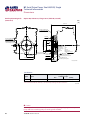
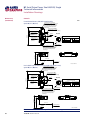
Dimensions
Twin port, ORB, remote filter
mm
Y
238 ±2.5
186.3 ±1.2
177.3 ±1.2
2x 136.2 ±1.2
2x 120 ±1.2
Servo gauge port "M4"
Port ISO 11926-1 - 7/16-20
∅24.5 max clearance dia for fitting
Control solenoid connector "C2"
Deutsch DT04-2P
Paint free
See view W for pin out 41.1 ±0.8
System port "B"
Port ISO 11926-1 - 1 5/16-12
W
Mounting flange
Flange 101-2
Per ISO 3019-1 (SAE B)
19.8 ±2.1
9.7 0-0.5
1 ±0.5
R0.8 max
5°
74.4 ±0.8
A
∅74.38 min
C
2x 59 ±0.8
B
∅101.6 0-0.05
2x 110.5 ±1.2
A
Z
Case drain port "L4"
Port ISO 11926-1 - 1 1/16-12
45°±
2x 147.3 ±1.2
C
Paint free
B
Charge inlet port "S"
Port ISO 11926-1 - 1 5/16-12
Name plate
Paint free
System port "A"
Port ISO 11926-1 - 1 5/16-12
X
A-A
B-B
C-C
89.5 ±0.8
89.5 ±0.8
91.2 ±0.8
(2x)
Shaft CL
Shaft CL
Shaft CL
P700 33 051-1
1
W (2:1)
Control solenoid
Connector “C1” & “C2”
Pin Assignment
Pin Assignment
2
P301 320
1
Supply
2
Ground
OR
1
Ground
2
Supply
T301 079
Please contact Sauer-Danfoss for specific installation drawings
32
11063344 • Rev EA • Dec 2012
H1 Axial Piston Pump, Size 045/053, Single
Technical Information
Installation Drawings
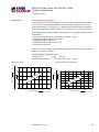
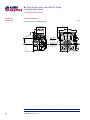
Dimensions
(continued)
Twin port, ORB, remote filter
Control solenoid connector "C1"
Deutsch DT04-2P
Paint free
See view W for pin out
Z
mm
206 ±2.5
2x 64.2 ±0.8
(1)
Servo gauge port "M5"
Port ISO 11926-1 - 7/16-20
∅24.5 max clearance dia for fitting
173.3 ±2.5
Charge gauge port "M3"
Port ISO 11926-1 - 9/16-18
90 ±0.8
Case drain port "L2"
Port ISO 11926-1 - 1 1/16-12
88.5 ±1.5
(29)
D
D
(129.7)
95.1 ±0.8
Approximate
center of gravity
(128)
D-D
81.5 ±0.8
174.8 ±1.2
Y
Shaft CL
199.8 ±1.2
E-E
E
F
F
t "E"
n por
4
ltratio6-1 - 7/8-1
fi
e
ChargISO 1192
t
r
o
P
filter
From
15°
(199.8)
93.5 ±0.8
6 ±0.5
E
64 ±0.8
60 ±0.8
Case gauge port "M14"
Port ISO 11926-1 - 7/16-20
∅21 max clearance dia for fitting
F-F
15°
System B gauge port "MB"
Port ISO 11926-1 - 9/16-18
58 ±0.8
Alternate charge pressure port ("AM3")
port ISO 11926-1 - 9/16-18
"
ort "F 4
ion p
-1
filtrat26-1 - 7/8
e
rg
Cha ISO 119
Port er
To filt
93.5 ±0.8
200 ±1.2
(199.8)
P700 33 051-2-3
Please contact Sauer-Danfoss for specific installation drawings
11063344 • Rev EA • Dec 2012
33
H1 Axial Piston Pump, Size 045/053, Single
Technical Information
Installation Drawings
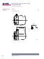
Dimensions
(continued)
mm
X
189.3 ±1.2
System A gauge port "MA"
Port ISO 11926-1 - 9/16-18
40 ±0.8
2x ∅14.3 +0.25
-0.13
CCW
CW
2x 73 ±0.25
P700 33 051-1-3
Please contact Sauer-Danfoss for specific installation drawings
34
11063344 • Rev EA • Dec 2012
H1 Axial Piston Pump, Size 045/053, Single
Technical Information
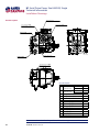
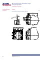
Installation Drawings
Controls
mm
2x 64.2 ±0.8
206 ±2.5
Electric Displacement Control (EDC),
option A2 (12 V) / A3 (24 V)
Case gauge port "M14"
Port ISO 1926-1 - 7/16-20
∅21 max clearance dia for fitting
Control solenoid
connector "C1"
Deutsch DT04-2P
paint free
Shaft CL
1
W (2:1)
Control solenoid
Connector “C1” & “C2”
Pin Assignment
Pin Assignment
Control solenoid
connector "C2"
Deutsch DT04-2P
paint free
58 ±0.8
2
1
Supply
2
Ground
OR
1
Ground
2
Supply
T301 079
P301 320
Mounting flange
147.3 ±1.2
173 ±2.5
Z
120.1 ±1.2
Mounting flange
Shaft CL
P700 332 58-45
Electric Displacement Control (EDC) with manual override,
Control manual override "C1"
option A4 (12 V) / A5 (24 V)
Depressing the plunger mechanically
2x 64.2±0.8
moves the control spool. Actuation
allows full stroke pump response as
per coil and rotation dependent
control logic
206 ±2.5
Case gauge port "M14"
Port ISO 1926-1 - 7/16-20
∅21 max clearance dia for fitting
Control solenoid
connector "C1"
Deutsch DT04-2P
paint free
Shaft CL
1
W (2:1)
Control solenoid
Connector “C1” & “C2”
Control solenoid
connector "C2"
Deutsch DT04-2P
paint free
Pin Assignment
Pin Assignment
58
2
P301 320
Mounting flange
1
Supply
2
Ground
OR
1
Ground
2
Supply
T301 079
Control manual override "C2"
Depressing the plunger mechanically
moves the control spool. Actuation
allows full stroke pump response as
per coil and rotation dependent
control logic
147.3 ±1.2
Z
173 ±2.5
Dimensions
(continued)
120.1 ±1.2
Shaft CL
Mounting flange
P700 33 399-45
Please contact Sauer-Danfoss for specific installation drawings
11063344 • Rev EA • Dec 2012
35
H1 Axial Piston Pump, Size 045/053, Single
Technical Information
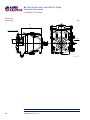
Installation Drawings
Dimensions
(continued)
Controls
mm
Forward-Neutral-Reverse (FNR) with manual override,
Control manual override "C1"
option A9 (12 V) B1 (24 V)
Depressing the plunger mechanically
206 ±2.5
2x 64.2 ±0.8
moves the control spool. Actuation
allows full stroke pump response as
per coil and rotation dependent
control logic
Case gauge port "M14"
Port ISO 1926-1 - 7/16-20
∅21 max clearance dia for fitting
Control solenoid
connector "C1"
Deutsch DT04-2P
paint free
Shaft CL
1
W (2:1)
Control solenoid
Connector “C1” & “C2”
Control solenoid
connector "C2"
Deutsch DT04-2P
paint free
Pin Assignment
Pin Assignment
58 ±0.8
2
1
Supply
2
Ground
OR
1
Ground
2
Supply
T301 079
P301 320
Mounting flange
Control manual overrid "C2"
Depressing the plunger mechanically
moves the control spool. Actuation
allows full stroke pump response as
per coil and rotation dependent
control logic
173 ±2.5
147.3 ±1.2
Z
120.1 ±1.2
Mounting flange
Shaft CL
P700 33 401-45
Non Feedback Proportional Electric Control (NFPE) with manual override,
Control manual override "C1"
option A8 (12 V) B8 (24V)
Depressing the plunger mechanically
206 ±2.5
2x 64.2 ±0.8
moves the control spool. Actuation
allows full stroke pump response as
per coil and rotation dependent
control logic
Case gauge port "M14"
Port ISO 1926-1 - 7/16-20
∅21 max clearance dia for fitting
Control solenoid
connector "C1"
Deutsch DT04-2P
paint free
Shaft CL
1
W (2:1)
Control solenoid
Connector “C1” & “C2”
Control solenoid
connector "C1"
Deutsch DT04-2P
paint free
Pin Assignment
Pin Assignment
58
2
P301 320
1
Supply
2
Ground
OR
1
Ground
2
Supply
T301 079
Mounting flange
Control manual override "C2"
Depressing the plunger mechanically
moves the control spool. Actuation
allows full stroke pump response as
per coil and rotation dependent
control logic
173 ±2.5
147.3 ±1.2
Z
120.1 ±1.2
Shaft CL
Mounting flange
P700 33 400 -45
Please contact Sauer-Danfoss for specific installation drawings
36
11063344 • Rev EA • Dec 2012
H1 Axial Piston Pump, Size 045/053, Single
Technical Information
Installation Drawings
Controls
Automotive control (AC) with manual override,
option A7 (12 V)/C2 (24 V)
V
Control connector ”CAN”
Deutsch DTM04-3P
Paint free
For using the connector
the plug may be removed
61.2 ±0.8
Control connector ”CC2”
Deutsch DTM04-12P -BPaint free
61.2 ±0.8
Mounting flange
2x 187.1 ±1.2
208.9 ±2.5
190.5 ±1.2
Control connector ”CC1”
Deutsch DTM04-12P -APaint free
Control connector ”CAN”
Deutsch DTM04-3P
Paint free
For using the connector
the plug may be removed
Control connector ”CC2”
Deutsch DTM04-12P -BPaint free
Shaft CL
Plug removing can cause
contamination issues
Control manual override ”C1”
Depressing the plunger mechanically
moves the control spool. Actuation
allows full stroke pump response as
per coil and rotation dependent
control logic.
Control connector ”CCC3”
Deutsch DT06-2S
Paint free
For using the connector
the plug may be removed
30.2 ±0.8
Control connector ”CC1”
Deutsch DTM04-12P -APaint free
mm
209 max
Dimensions
(continued)
V
Control manual override ”C2”
Depressing the plunger mechanically
moves the control spool. Actuation
allows full stroke pump response as
per coil and rotation dependent
control logic.
89.2 ±0.8
“PPU” wire harness
is factory installed to speed sensor
P700 52 604
Please contact Sauer-Danfoss for specific installation drawings
11063344 • Rev EA • Dec 2012
37
H1 Axial Piston Pump, Size 045/053, Single
Technical Information
Installation Drawings
Displacement limiters
Dimensions
(continued)
mm
Displacement limiter, option B and D
2x (116.1)
2x 106.3 ±0.8
2x 74.4 ±0.8
2x displacement
limiter screw
Wrench size
4 internal hex
2x displacement
limiter seal nut
Wrench size
13 external hex
Torque to 23.0 nm
P700 33 194
Please contact Sauer-Danfoss for specific installation drawings
38
11063344 • Rev EA • Dec 2012
H1 Axial Piston Pump, Size 045/053, Single
Technical Information
Installation Drawings
Endcap
mm
Twin port, code 62 metric 4 bold FLG, option D6, D8, F2, and F3
4x 25.4 ±0.25
2x 11.9 ±0.25
186.32 ±1.2
System port "B"
∅19-450 bar
Split flange boss
Per ISO 6162
M10x1.5
18 full thread depth
59 ±0.8
59 ±0.8
Installation Drawings
(continued)
System port "A"
∅19-450 bar
Split flange boss
Per ISO 6162
M10x1.5
18 full thread depth
90 ±0.8
System ports "A" &"B"
P700 33 203
Please contact Sauer-Danfoss for specific installation drawings
11063344 • Rev EA • Dec 2012
39
H1 Axial Piston Pump, Size 045/053, Single
Technical Information
Installation Drawings
Installation Drawings
(continued)
Filtration
mm
Suction filtration, option L
A-A
89.5 ±0.8
177.3 ±1.2
Shaft CL
A
Charge inlet port "S"
Port ISO 1926-1 - 1 5/16-12
A
P700 33 466
Please contact Sauer-Danfoss for specific installation drawings
40
11063344 • Rev EA • Dec 2012
H1 Axial Piston Pump, Size 045/053, Single
Technical Information
Installation Drawings
Filtration
Installation Drawings
(continued)
mm
Remote full flow charge pressure filtration, option P for end cap option F
199.8 ±1.2
60 ±0.8
A
A
B
B
15°
93.5 ±0.8
(199.8)
"F"
port -14
ation
/8
e filtr 926-1 - 7
rg
a
h
1
C
ISO 1
Port er
To filt
177.3 ±1.2
93.5 ±0.8
t "E"
n por
ltratio - 7/8-14
fi
e
-1
Charg O 11926
IS
Port lter
fi
From
(199.8)
6 ±0.5
15°
89.5 ±0.8
C
Charge inlet port "S"
Port ISO 11926-1 - 1 5/16-12
Shaft CL
C
P700 33 360
Please contact Sauer-Danfoss for specific installation drawings
11063344 • Rev EA • Dec 2012
41
H1 Axial Piston Pump, Size 045/053, Single
Technical Information
Installation Drawings
Installation Drawings
(continued)
Filtration
mm
External full flow charge pressure filtration, option E
199.8 ±1.2
A-A
A
A
93.5 ±0.8
"
ort "E 4
ion p
-1
filtrat26-1 - 7/8
e
rg
Cha ISO 119
Port filter
from
60 ±0.8
(199.8)
6 ±0.5
15°
P700 45 735
Please contact Sauer-Danfoss for specific installation drawings
42
11063344 • Rev EA • Dec 2012
H1 Axial Piston Pump, Size 045/053, Single
Technical Information
Installation Drawings
Installation Drawings
(continued)
Speed and Temperature Sensor
Speed and Temperature Sensor, option H for mounting flange option K
mm
19.8 ±2.1
Mounting flange
Flange 101-2
Per ISO 3019-1 (SAE B)
9.7 0-0.5
1 ±0.5
2x ∅14.3 +0.25
-0.13
101.6 0-0.05
23 ±0.5
45°
±5°
R0.8 max
Z
Paint free
2x 73 ±0.25
106 ±0.8
Speed sensor connector
Deutsch DTM04-6P
Paint free
107.6 ±0.8
125.2 ±2.5
P700 33 206
Z (2:1)
Speed sensor
Connector
PIN
1
2
3
4
5
6
ASSIGNMENT
Output signal 2
Direction
Output signal 1
Supply
Ground
Temperature
1
6
3
4
P301 310
Please contact Sauer-Danfoss for specific installation drawings
11063344 • Rev EA • Dec 2012
43
Products we offer:
• Bent Axis Motors
• Closed Circuit Axial Piston Pumps
and Motors
• Displays
• Electrohydraulic Power Steering
• Electrohydraulics
• Hydraulic Power Steering
Sauer-Danfoss is a global manufacturer and supplier of highquality hydraulic and electronic components. We specialize in
providing state-of-the-art technology and solutions that excel in
the harsh operating conditions of the mobile off-highway market.
Building on our extensive applications expertise, we work closely
with our customers to ensure exceptional performance for a broad
range of off-highway vehicles.
We help OEMs around the world speed up system development,
reduce costs and bring vehicles to market faster.
Sauer-Danfoss – Your Strongest Partner in Mobile Hydraulics.
• Integrated Systems
• Joysticks and Control Handles
• Microcontrollers and Software
Go to www.sauer-danfoss.com for further product information.
• Open Circuit Axial Piston Pumps
• Orbital Motors
• PLUS+1™ GUIDE
• Proportional Valves
• Sensors
• Steering
Wherever off-highway vehicles are at work, so is Sauer-Danfoss.
We offer expert worldwide support for our customers, ensuring
the best possible solutions for outstanding performance. And with
an extensive network of Global Service Partners, we also provide
comprehensive global service for all of our components.
• Transit Mixer Drives
Please contact the Sauer-Danfoss representative nearest you.
Members of the Sauer-Danfoss Group:
Local address:
Comatrol
www.comatrol.com
Schwarzmüller-Inverter
www.schwarzmueller-inverter.com
Turolla
www.turollaocg.com
Valmova
www.valmova.com
Hydro-Gear
www.hydro-gear.com
Sauer-Danfoss-Daikin
www.sauer-danfoss-daikin.com
11063344 • Rev EA • Dec 2012
Sauer-Danfoss (US) Company
2800 East 13th Street
Ames, IA 50010, USA
Phone: +1 515 239 6000
Fax:
+1 515 239 6618
Sauer-Danfoss ApS
DK-6430 Nordborg, Denmark
Phone: +45 7488 4444
Fax:
+45 7488 4400
Sauer-Danfoss GmbH & Co. OHG
Postfach 2460, D-24531 Neumünster
Krokamp 35, D-24539 Neumünster, Germany
Phone: +49 4321 871 0
Fax:
+49 4321 871 122
Sauer-Danfoss-Daikin LTD.
Shin-Osaka TERASAKI 3rd Bldg. 6F
1-5-28 Nishimiyahara, Yodogawa-ku
Osaka 532-0004, Japan
Phone: +81 6 6395 6066
Fax:
+81 6 6395 8585
www.sauer-danfoss.com