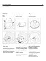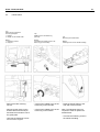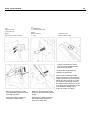
1
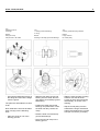
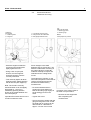
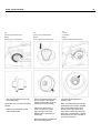
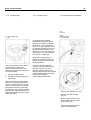
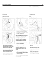
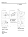
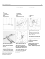
STIHL TS 360,350 AVE
1
Service Manual
Cutquik
TS 360, 350 AVE
Only the assemblies and
components typically featured in
the TS 360, 350 AVE are
described in this Service Manual.
All other repair work is described
in Manual 08 S.
You should make use of the
illustrated parts list while carrying
out repair work. They show the
installed positions of the individual
components and assemblies.
Microfilmed parts list are always
more up to date than printed lists!
Refer to the "Technical Information
Bulletins" for engineering changes
which have been introduced since
publication of this service manual.
Service manuals and technical
information bulletins describing
engineering changes are intended
exclusively for the use of STIHL
servicing dealers and staff and
must not be passed on to third
parties.
The STIHL Special Tools manual
lists all special servicing tools
currently available from STIHL.
Always use original STIHL
replacement parts.
Original STIHL parts can be
identified by the STIHL part
number, the STIHl logo
and the STIHL parts symbol ( .
The symbol may appear alone
on small parts.
A fault on the machine may have
several causes. Consult the
"troubleshooting charts" when
tracing faults.
STIHl
STIHL TS 360,350 AVE
2
CONTENTS
1.
Tightening torques
2
4.1.3
4.1.4
4.1.5
4.1.6
4.1.7
Ignition lead plug
Ignition lead
Stop switch lead
Stop switch
Flywheel
16
17
18
18
19
2.
Drive for abrasive body
3
2.1
2.2
Bearing with guard
Check the axial and radial truth
of running
V-belt
V-belt pulley
(clutch drum)
3
7
9
5.
AV handle system/frame
20
9
5.1
5.2
Buffer ring
Handle frame
20
21
3.
Air filter
11
6.
Special servicing tools and
aids
23
3.1
3.2
Air filter
Filter housing
11
12
Special servicing tools
Servicing aids
23
23
4.
Ignition system
13
4.1
4.1.1
4.1.2
4.1.2.1
4.1.2.2
Repairing the components
Spark plug
Module plate
Ignition timing
Removal Installation
13
13
15
15
15
1.
Tightening torques
2.3
2.4
Fastener
Self-tapping
cheese-head screw
Flat head screw
Cheese-head screw
Cheese-head screw
Cheese-head screw
Countersunk screw
Cheese-head screw
Cheese-head screw
Cheese-head screw
Cheese-head screw
Locking screw
Nut
Nut
Nut
Hexagon bolt
Cheese-head screw
Nut
1) Only for USA
Thread
size
IS-B4,2x9,5
M4x12
IS-M4x16
IS-M5x33
IS-M5x30x22
M6x12
IS-M6x18
IS-M6x18
IS-M6x24
IS-M6x40
M8
M10X1
M10x1 L
M10x1 L
M10x35
IS-M6x20
M12x0,75
M14x1,25
6.1
6.2
For component
Rubber vibration buffer/
handle frame
Guard for cutting wheel
Module plate
Fan housing
Fan housing
Limit stop/bearing
Filter housing
Buffer ring
Buffer ring/handle frame
Support/handle frame
Filter cover
Flywheel
V-belt pulley
V-belt pulley, front
Connecting piece
Connecting piece
Stop switch
Spark plug
Torque
Nm
Remarks
(kpm)
3.0
3.3
4.0
5.0
5.0
7.0
6.5
7.0
7.5
7.5
12.0
27.5
32.5
37.5
47.5
8.5
2.7
27.5
(0.3)
(0.33)
(0.4)
(0.5)
(0.5)
(0.7)
(0.65)
(0.7)
(0.75)
(0.75)
(1.2)
(2.75)
(3.25)
(3.75)
(4.75)
(0.85)
(0.27)
(2.75)
1)
STIHL TS 360,350 AVE
2.
DRIVE FOR ABRASIVE
BODY
2.1
Bearing with guard
3
Top:
1 = Guard (new version)
2 = Size 19 fastening bolts for
bearing
Bottom:
1 = Guard (former version)
2 = Size 13 fastening bolts for
bearing
Top:
Removing the bearing
Top:
Removing the axial clamp ring
1 =Thrust washer
Bottom:
Pliers 0811 611 8200
Bottom:
Unscrewing the nut
- Check axial and radial truth of
running; see 2.2.
- Lift the bearing with guard out of
the V-belt.
- Unscrew the fastening bolts on
the bearing and remove the
guard.
- Draw the axial clamp ring off the
shaft.
Note: The former machine versions
feature a steel guard and size 13
hexagon bolts.
- Remove the thrust washer.
- Lock the V-belt pulley. Unscrew
the nut and draw the V-belt pulley
off the shaft
Important! The nut has a left-hand
thread.
STIHL TS 360,350 AVE
4
Top:
1 = Woodruff key
2 = Washer
Top:
Flat head screws
Top:
1 = Rubber washer
2 = Disk
Bottom:
Removing the shaft
Bottom:
Removing the flange
Bottom:
Removing the bearing
- Remove the Woodruff key
from the groove in the shaft.
- Remove the washer from the
shaft.
- Draw the shaft out of the
deep-groove ball bearings.
- Unscrew both flat head
screws and remove them
together with the spring
washers.
- Remove the disk and rubber
washer from the flange and
guard.
Note: Note the number of spring
washers.
- Remove the bearing from the
guard.
- Remove the flange from the
guard.
STIHL TS 360,350 AVE
Top:
Removing the rubber ring
Bottom:
1 = Rubber washer
2 = Disk
5
Top:
1 = Countersunk screw
2 = Limit stop
3 = Cheese-head screw
4 = Rubber vibration buffer
Bottom:
Pliers 0811 641 8380
- Remove the rubber ring from the
bearing.
- Unscrew the countersunk
screw and remove the limit
stop.
- Remove the rubber washer and
disk from the bearing.
- Unscrew the cheese-head
screw in order to replace the
rubber vibration buffer.
Note: The limit stop and rubber
vibration buffer only feature in
machines for the USA.
Top:
Removing a
circlip
Bottom:
Pressing out the deep-groove ball bearings
with drift pin 4119 893 7200
- Remove the circlips from
the grooves before
removing the deep-groove
ball bearings.
- Force both deep-groove
ball bearings and the ring
out of the bearing with the
drift pin.
STIHL TS 360,350 AVE
Top:
Fastening bolts for
the flange
Bottom:
Fitting the circlip
with pliers 0811 641 8380
- Unscrew the fastening screws on
the flange and remove the flange
from the guard.
The parts are assembled in reverse
order.
Note: Particular care must be taken
when carrying out the following
work.
- Place the circlip in one of the
bearing grooves.
6
Top:
1 = Deep-groove ball bearing
2 = Ring
Bottom:
Pressing in the deep-groove ball bearings
- Slide the first deep-groove ball
bearing onto the shaft, then the
ring and the second deep-groove
ball bearing.
- Position the deep-groove ball
bearings and press them in with
the shaft until they contact the
circlip.
- Draw the shaft out of the deepgroove ball bearings.
- Place the second circlip in the
bearing groove.
Top:
Correctly positioned spring washers
Bottom:
Longer collar on
the V-belt pulley
- Slide the same number of spring
washers onto the flat head
screws as were removed during
disassembly, as shown in the
drawing.
- Slip the V-belt pulley onto the
shaft with the longer chamfered
edge first and tighten the nut with
a torque of 37.5 Nm (3.75 kpm).
STIHL TS 360,350 AVE
7
2.2
Tightening
the segment
1 = Fastening bolts
2 = Segment
- Place the segment under the
rear bolt on the bearing and
lightly tighten the bolt.
- Using a size 13 open-jaw
wrench, turn the segment
clockwise until the V-belt is
correctly tensioned.
- Then securely tighten all three
fastening bolts, starting with the
bolt at the rear (with segment).
Note: The V-belt is correctly
tensioned when it can be slightly
depressed (5 - 10 mm) by
moderately pressing with the
fingers in the middle between the
two V-belt pulleys.
Important! Excessive tension in the
V-belt increases the wear.
Check the axial and
radial truth of running
Top:
Fitting the test wheel
1 = Arresting grooves
2 = Arresting lugs
1 = Test wheel 5910 851 6100
2 = Gauge holder 5910 850 6000
3 = Dial gauge 0000 890 9100
Bottom:
Test equipment in position
Since changes in the shaft
diameter (due to scoring etc.) can
affect the radial truth of running of
the cutting wheel, it is normally
sufficient carefully to inspect the
shaft around the cutting wheel
mount.
The axial truth of running, on the
other hand, depends on the state of
various components and must
therefore be determined by
measurement.
- Fit the test wheel and then
position the thrust washer so
that the arresting lugs engage in
the arresting grooves in the
shaft.
- Tighten the screw.
- Secure the gauge holder with dial
gauge to the guard cover so that
the axial truth of running can be
determined for a diameter of
approx. 130 mm over one full
revolution of the wheel. Refer to
the table "Test procedure".
- Remove the test equipment
after completing the
measurement.
STIHL TS 360,350 AVE
Test procedure
Radial truth of running:
Visual inspection
of the spindle (shaft)
Axial truth of running:
Check the axial truth of
running with the STIHL
test wheel or diamond
cutting wheel (over a
diameter of 130 mm)
8
Actual condition
Possible causes
Remedy
Wear marks or scoring
around the cutting wheel
mount
Fastening screw loose,
use of wrong cutting wheels
(diameter of mount > 20 mm
or > 22 mm)
Replace the
spindle (shaft)
Axial eccentricity
≤ 0.15 mm
> 0.15 mm
Damaged or uneven contact
surfaces of the thrust washers
(especially the inner thrust
washer); contact surfaces not
plane; genuine STIHL
parts have not been used
None
Dirt; thrust washers or
Replace the
cutting wheel fitted incorrectly; thrust washers
application of force when
cutting or during transport
Spindle (shaft)
damaged
Incorrect handling,
use of force
Replace the
spindle (shaft)
Distinct radial play in the
bearing seat spindle
bearing defective
Deep-groove ball bearings
damaged by exposure to dirt
and/or bearing seat worn
down at the spindle
Replace the spindle
and deep-groove
ball bearings
STIHL TS 360,350 AVE
2.3
9
V-belt
2.4
Top:
Fastening screws for the
connecting piece and fastening
screw on the front handle
Bottom:
Removing the connecting piece
V-belt pulley
(clutch drum)
Top:
Stop screw 1107 191 1200
Connecting piece with
V-belt in position
Bottom:
Stop screw in cylinder
- Remove the V-belt.
- Place a new V-belt in the
connecting piece.
- Position the connecting piece
and retighten the fastening
screws.
Note: Check the position of the
V-belt and that it moves easily
before tightening the fastening
screws.
- Remove the bearing with guard;
see 2.1.
- Unscrew the fastening screws
on the connecting piece and on
the front handle.
- Push the power unit aside slightly
and remove the connecting piece.
Tighten the two cheese-head
screws with a torque of 8.5 Nm
(0.85 kpm) and the hexagon
screw with a torque of 47.5 Nm
(4.75 kpm).
- Replace the bearing with guard;
see 2.1.
- Remove the V-belt; see 2.3.
- Unplug the ignition lead.
- Unscrew the spark plug and
screw in the stop screw
instead, turning it into the
cylinder as far as possible, so
that the crank shaft is arrested.
STIHL TS 360,350 AVE
10
Top:
Unscrewing the fastening nut
Top:
Forcing out the needle sleeve
Top:
1 = Disk
2 = Bushing
Bottom:
Assembly pin 1119 893 7200
Bottom:
Friction surface of the clutch drum
Bottom:
Correctly positioned needle sleeve
- Unscrew the fastening nut from
the V-belt pulley
Important! The nut has a left-hand
thread.
- Draw the V-belt pulley off the
crank shaft journal.
- Check the needle sleeve and
force it off the V-belt pulley
from the clutch side using an
assembly pin if necessary.
- Check the clutch drum; it
must not show any major
signs of wear or scoring.
Replace the V-belt pulley if
necessary.
- Draw the bushing and disk off
the crank shaft journal.
The parts are assembled in
reverse order.
Note: The assembly pin must be
positioned on the thicker, beaded
side of the needle sleeve and
forced in from the clutch drum
side until it is flush with the inner
edge of the V-belt pulley. Tighten
the fastening nut with a torque of
32.5 Nm (3.25 kpm).
STIHL TS 360,350 AVE
3.
AIR FILTER
3.1
Air filter
Top:
Screw plug on top of
the filter
Bottom:
Removing the prefilter
11
Top:
Unscrewing the wing nut
Bottom:
Removing the main filter
1 = Cover lid
Removing the auxiliary filter
- Rinse the prefilter in clean
naphtha if it is extremely dirty.
Note: The prefilter must be
completely dry before it is
replaced.
- Unscrew the wing nut on the
screw plug
- Remove the main filter and
press the cover lid out of the
main filter.
The purpose of the air filter is to
collect the dirt entrained with the
combustion air and thus minimize
the amount of wear in the power
unit.
- Before removing the filter, close
the choke shutter so that dirt
cannot enter the carburetor.
This is done by drawing out the
choke.
Clogged filters reduce the engine
efficiency, increase the fuel
consumption and make it more
difficult to start the equipment.
- Unscrew the screw plug on the
filter cover and remove the filter
cover.
For this reason, the air filter
must always be cleaned as
soon as the engine power
deteriorates.
- Remove the prefilter from the
main filter and knock it clean.
Note: The main filter must be
replaced if it is soiled.
- Draw the auxiliary filter off the
flange bolt, gently tap it clean
and rinse in a clean, nonflammable solution (such as hot
soapy water).
Note: The auxiliary filter must be
replaced immediately if the flock
coating is defective.
STIHL TS 360,350 AVE
3.2
12
Filter housing
Top:
Plug on ignition lead
Bottom:
Grommet
- Remove the air filter; see 3.1.
- Remove the fan housing;
see 4.1.7.
- Disconnect the ignition lead from
the spark plug.
- Draw the grommet for the ignition
lead out of the filter housing.
Top:
Locking screw
Bottom:
Fastening screws for the
filter housing
Top:
Removing the filter housing
Bottom:
Positioning the filter housing
- Unscrew the locking screw from
the filter housing.
The parts are assembled in
reverse order.
- Unscrew the fastening screws
from the filter housing.
Note: Draw the manifold through
the opening before positioning
the filter housing and tighten the
fastening screws with a torque of
6.5 Nm (0.65 kpm). Coat the
thread of the locking screw with
Loctite (see 6.2) and tighten with
a torque of 12.0 Nm (1.2 kpm).
Note: The screws at the rear are
located below the manifold.
- Draw the filter housing upwards,
pressing the manifold out through
the opening at the same time.
STIHL TS 360,350 AVE
4.
IGNITION SYSTEM
Important! Utmost care must be
taken both during troubleshooting
and when carrying out maintenance and repair work on the
ignition system. The high voltages
may cause fatal accidents!
13
4.1
Repairing
the components
4.1.1
Spark plug
Top: Checking the
electrode gap with a caliper
gauge
Bottom:
Adjusting the ground electrode
with a Bosch setting gauge
Module plate
Troubleshooting in the ignition
system should always start with
the spark plug.
First check the spark plug designation if the machine refuses to
start, if the engine power is
unsatisfactory or if the ignition
cuts out, etc. Only Bosch spark
plugs of type WSR 6 F or NGK
BPMR 7 A may be used. Other
types of spark plug and plugs
made by other manufacturers
cannot be used on account of the
large electrode size.
The STIHL Cutquiks TS 360,
350 AVE are fitted with a
transistorized (breakerless)
magneto-ignition system that is
not dependent on external power
supplies (battery, dynamo, etc.).
The ignition system basically
comprises the module plate and
flywheel and is easily accessible.
Spark plug blackened or charred:
- Clean with brass wire brush and
then blow through with
compressed air.
Note: Do not use a steel wire
brush.
Spark plug covered with oil:
- Wash the insulator nose with a
grease solvent and then blow
through with compressed air.
Electrode gap:
The gap between electrodes
increases as a result of the
natural burn-off.
- The electrode gap must be
checked regularly with a caliper
gauge. The gap must be equal
to 0.5 mm.
- The ground electrode must be
adjusted accordingly if necessary.
Important! A new spark plug
must be fitted without fail if the
electrodes have burned down
severely.
STIHL TS 360,350 AVE
Checking the spark plug:
The spark plug can only be checked
correctly with the aid of a spark plug
tester.
As a provisional measure, the spark
plug can also be inserted in the
ignition lead plug and connected to
ground after being dismantled and
cleaned. Considerable sparking
must be evident at the electrodes
when the starter is pulled.
14
Important! Never touch live parts:
the high voltages can cause fatal
accidents.
Note: If in doubt, install a new spark
plug in place of the old one.
The cable connections must then
be checked if sparking is not
observed although the spark plug is
in perfect condition.
Note: Frayed insulation on the
ignition and stop switch leads can
cause short-circuits to ground
preventing the engine from
starting or causing it to
malfunction.
Installation of the spark plug:
- Clean the spark plug and check
that the gasket is undamaged.
- Screw in the spark plug and
tighten with a torque of 27.5 Nm
(2.75 kpm).
The appearance of the insulator nose, the "face of the spark plug", is a major source of information on
the effects of different operating conditions:
Condition of the insulator nose
Examples of corresponding
operating conditions
Normal:
Greyish-yellow to brown, dry
Engine OK,
correct spark plug
(heat range as specified)
Charred:
Velvety, dull black layer
of soot
Mixture too rich, lack of air
(air filter clogged,
choke partly closed),
electrode gap too large,
wrong spark plug
(heat range too high)
Covered with oil:
Layer of damp carbon oil
and soot
Fuel mixture contains
too much oil
Overheated:
Beading on the insulator nose,
corroded electrodes
Mixture too lean, spark plug
loose, wrong spark plug
(heat range too low)
STIHL TS 360,350 AVE
4.1.2
Module plate
15
4.1.2.1 Ignition timing
4.1.2.2 Removal and installation
Top:
Grommet
Bottom:
Fastening bolts for
the module plate
1 = High-voltage output
2 = Tab
In electronically controlled
(breakerless) magneto-ignition
systems, the ignition timing has
been set at 2.1 mm before the
UDC at n = 8000 rpm and cannot
be adjusted. Taking into account
the permissible variation in the
elelctronic circuit, this value may
range from 1.9 to 2.5 mm before
the UDC at n = 8000 rpm.
Since these systems are not
subject to mechanical wear, the
ignition timing does not change
during operation.
The module plate contains all the
functional parts required for
ignition timing control. Only two
electrical connections emerge from
the coil assembly:
1. The high-voltage output
2. The tab for connecting the stop
switch lead
Correct functioning of the module
plate can only be checked with the
aid of a complex test unit. For this
reason, the workshop tests should
be limited exclusively to checking
the sparking. The complete module
plate must be replaced if there is no
spark (although the leads and stop
switch are intact).
However, defects inside the
circuitry may cause the timing to
change in such a way as to
produce positive spark control
although the timing itself is outside
the permissible range so that the
starting and operating
characteristics deteriorate.
- Remove the flywheel; see 4.1.7.
- Remove the filter housing;
see 3.2.
- Remove the grommet for the
ignition lead from the mount
of the crank case.
- Unscrew the fastening bolts
from the module plate.
STIHL TS 360,350 AVE
16
4.1.3
Top:
Stop switch lead
Bottom:
Drawing the unscrewed
ignition lead out of the
high-voltage dome
Ignition lead plug
Top:
1 = Ignition lead plug
2 = Grommet
Markings on the module plate
and crank case
Bottom:
Removing the spiral spring
from the ignition lead plug
- Unscrew the ignition lead from
the contact pin and draw it out of
the high-voltage dome.
Note: The high-voltage dome must
be filled with STIHL multipurpose
grease (0781 120 1109) before
screwing in the ignition lead.
Important! Graphite (Molykote)
grease and silicone insulating
paste must not be used.
- Slide the protective sleeve over
the high-voltage dome.
- Remove the module plate
from the crank shaft journal
and disconnect the stop switch
lead from the module plate.
- Draw the module plate slightly
forwards, pulling the ignition
lead out of the grommet in the
housing at the same time.
- Remove the protective sleeve
from the high-voltage dome.
- Replace the module plate and
loosely screw in the screws.
- Remove the fan housing;
see 4.1.7.
Important! A washer must be
placed under the head of each
screw.
- Disconnect the ignition lead
from the spark plug and draw
the grommet out of the filter
housing.
- Align the module plate so that
the markings match. Tighten the
fastening screws with a torque of
4.0 Nm (0.4 kpm).
- Grip the spiral spring with
suitable pliers and draw it
out of the ignition lead plug.
The remaining parts are assembled
in reverse order.
STIHL TS 360,350 AVE
17
4.1.4
Top:
Drawing the ignition lead
into its plug
Bottom:
Inserting the spiral spring
Ignition lead
Top:
Protective grommet
Correct position of the spiral spring in the
recess of the ignition lead plug.
Bottom:
Removing the ignition lead
1 = Grommet
- Press the hook of the spiral
spring into the middle of the
conductor cross-section
approx. 15 mm from the
end of the ignition lead.
- Pull back the ignition lead until
the spiral spring is located in the
recess of the ignition lead plug.
- Press the grommet into the
mount in the filter housing and
slide the spark plug terminal
onto the spark plug.
- Remove the spiral spring
from the ignition lead and
draw the plug off the lead.
- Coat the end of the ignition
lead with oil over a length of
approx. 20 mm.
- Slip the plug onto the
ignition lead.
- Grip the ignition lead with
suitable pliers and draw it out
of its plug.
- Replace the fan housing; see
4.1.7.
- Remove the module plate;
see 4.1.2.2.
- Draw the protective grommet
off the ignition lead.
- Draw the ignition lead out of
the grommet in the crank case.
STIHL TS 360,350 AVE
18
4.1.5 Stop switch lead
Top:
1 = Insulating tube
2 = Grommets
3 = Ignition lead plug
Top:
1 = Contact sleeve
2 = Protective grommet
Bottom:
Piercing the centre of
the ignition lead
Bottom:
Removing the stop switch lead
1 = Grommet
4.1.6 Stop switch
1 = Fastening nut
2 = Plate
3 = Adapter
- Remove the filter housing; see
3.2.
- Draw the contact sleeve of the
stop switch lead out of the stop
switch; see 6.1.5.
- Unscrew the fastening nut on the
stop switch and remove the plate.
- Remove the stop switch from the
adapter.
The parts are assembled in
reverse order.
- Draw the insulating tube and
grommets off the ignition lead.
- Remove the ignition lead; see
4.1.4.
- Remove the ignition lead plug;
see 4.1.3.
- Slide the protective grommet
back a little and draw the contact
sleeve of the stop switch lead out
of the stop switch.
- Cut the new ignition lead to the
required length (length as
specified in the spare parts list
or equal to that of the old lead).
Note: The centre at the end of the
lead which is screwed into the
ignition module must first be
pierced with a sharp tool.
- Draw the stop switch lead out of
the grommet in the crank case.
The parts are assembled in
reverse order.
Note: The stop switch must be
positioned so that the groove in
the threaded insert points
upwards. Tighten the fastening nut
with a torque of 2.7 Nm (0.27 kpm).
STIHL TS 360,350 AVE
4.1.7
19
Flywheel
Top:
Fastening bolts on
the fan housing
Bottom:
Fastening nut on the
flywheel
Removing the flywheel:
- Use the stop screw to arrest the
piston; see 2.4.
- Unscrew the fastening bolts from
the fan housing and remove the
fan housing.
- Unscrew the fastening nut for the
flywheel from the crank shaft.
Top:
Extractor 1106 890 4501
Top:
1 = Magnet pole
2 = Flywheel
Bottom:
Extracting the flywheel
Bottom:
Woodruff key for flywheel
- Screw the extractor onto the
flywheel and draw the flywheel
off the crank shaft.
- There must not be any signs of
cracking or other damage on the
flywheel and magnet pole,
otherwise the flywheel must be
replaced.
Installing the flywheel:
- Ensure that the Woodruff key is
fitted correctly.
Important! The journal of the
crank shaft and the hole in the
flywheel hub must be degreased
with a commercial solvent-based
degreasing agent without
chlorinated or halogenated
hydrocarbons.
- Position the flywheel.
- Fit the fastening nut and tighten
with a torque of 27.5 Nm
(2.75 kpm).
The remaining parts are
assembled in reverse order.
STIHL TS 360,350 AVE
5.
AV HANDLE SYSTEM/
FRAME
5.1
Buffer ring
Top:
1 = Fastening screw on
the front handle
2 = Middle screw
Bottom:
Fastening screws on the buffer ring
20
Top:
1 = Fastening screws in the
buffer ring (fan side)
2 = Middle screw
Bottom:
Unscrewing the middle screw
1 = Fastening screws in the buffer ring
Fitting the middle screw
1 = Tear guard
- Remove the filter housing in
order to replace the buffer ring
on the handle; see 3.2.
- Unscrew the middle screw and
the fastening screws in the buffer
ring, then remove the buffer ring.
The parts are assembled in
reverse order.
The crank case, handle frame and
front handle are connected by
means of ring-shaped rubber
vibration buffers. Damaged buffers
(buffer rings) must always be
replaced.
- Unscrew the fastening screw for
the front handle from the handle
bracket.
- Unscrew the middle screw from
the connecting piece and remove
the handle bracket.
- Unscrew the fastening screws in
the buffer ring and remove the
buffer ring from the handle
bracket.
- Unscrew the middle fastening
screw in the buffer ring and
remove it together with the tear
guard.
- Unscrew the fastening screws in
the buffer ring and remove the
buffer ring.
Note: The tear guard must be
fitted under the middle screw on
the side of the connecting piece
and fan side. Tighten the fastening
screws of the buffer rings with a
torque of 7.0 Nm (0.7 kpm).
STIHL TS 360,350 AVE
5.2
21
Handle frame
Top:
Removing the end sleeve
from the guide plate
1 = Slit pin
2 = Nipple on the throttle cable
Top:
Middle screw of the buffer ring
(fan side)
Bottom:
1 = Fastening screws
2 = Support
Bottom:
Unscrewing the middle screw in the
buffer ring (on the handle)
Top:
Removing the handle frame
Bottom:
Fastening screw in the handle moulding
- Remove the filter housing;
see 3.2.
- Unscrew the middle screw in the
buffer ring on the fan side.
- Draw the handle frame to the
rear and off the machine.
- Disconnect the nipple on the
throttle cable from the slit pin
and draw the end sleeve out of
the guide plate.
- Unscrew the middle screw in the
buffer ring on the handle.
Note: The following steps are
required in order to replace the
handle frame.
- Unscrew the fastening screws
from the bottom support.
- Unscrew the fastening screw in
the handle moulding.
STIHL TS 360,350 AVE
Top:
Fastening screws
for the buffer ring
Bottom:
Removing the handle moulding
22
Top:
1 = Helical spring
2 = Starting throttle button
Bottom:
Removing the pin
1 = Hole
1 = Fastening screw
2 = Rubber vibration buffer
- Unscrew the fastening screw
from the rubber vibration buffer
and remove the buffer.
The parts are assembled and
refitted in reverse order.
Note: Press the starting throttle
button onto the pin until it engages.
Tighten the fastening screws of the
buffer ring with a torque of 7.0 Nm
(0.7 kpm), the fastening screws in
the support with a torque of 7.5 Nm
(0.75 kpm) and the fastening screw
in the handle moulding with a
torque of 3.0 Nm (0.3 kpm).
- Remove the fastening screws
from the buffer and then remove
the buffer ring itself.
- Draw the starting throttle button
off the pin and remove the helical
spring.
- Draw the handle moulding up
and off the handle frame.
- Push the pin inwards and out of
the handle frame through the
hole on the other side.
STIHL TS 360,350 AVE
23
6.
Special servicing tools and aids
6.1
Special servicing tools
No.
Part name
1
Pliers A 10
0811 611 8200
2
3
Pliers C 19
Test wheel
0811 641 8380
5910 851 6100
4
5
6
7
Gauge holder
Dial gauge
Stop screw
Assembly pin
5910 850 6000
0000 890 9100
1107 191 1200
1119 893 7200
8
9
10
11
Extractor
Size 13 insert
Size 17 insert
Torque wrench
12
Torque wrench
13
Insert I-5 x 150
1106 890 4501
5910 893 5608
5910 893 5610
5910 890 0301
5910 890 0302
5910 890 0311
5910 890 0312
0812 542 2104
14
Screwdriver with T-handle
QI-5x150
5910 890 2400
6.2
Servicing aids
No.
Part name
Part No.
Part No.
Application
Outer circlip on the
thrust washer
Inner race of the bearing
Checking the radial truth of running of the
cutting wheel mount
Checking the radial truth of running
Checking the radial truth of running
Arresting the crank shaft
Forcing the needle sleeve into
and out of the V-belt pulley
Extracting the flywheel
Crank shaft nut
Hexagon bolt of the connecting piece
Tightening the cheese-head screws
with internal star
For all hexagon socket head screws
Application
1
Commercial solvent-based
degreasing agent without
chlorinated and
halogenated hydrocarbons
Cleaning the crank shaft journal
2
Lubricating grease
0781 120 1111
Needle sleeve
3
Solid adhesive
(Loctite 270)
0786 111 1109
Locking screw for air filter