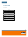
1
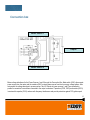
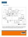
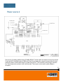
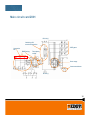
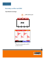
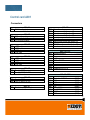
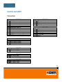
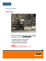
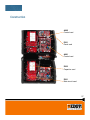
Service Manual
KempGouge™ ARC 800
1
Table of contents
General......................................................................................................................................3
Technical data.......................................................................................................................... 4
Main circuit diagram................................................................................................................5
Connection box....................................................................................................................... 6
Power source 1........................................................................................................................ 7
Power source 2........................................................................................................................ 8
Main circuit card Z001............................................................................................................ 9-10
Connectors............................................................................................................11
Operational measurings........................................................................................12
Capacitor card Z002............................................................................................................... 13
Secondary rectifier card Z003................................................................................................ 14
Operational measurings........................................................................................15
Control card A001.................................................................................................................... 16
Connectors............................................................................................................17-18
Leds...................................................................................................................... 19
Jumper settings.....................................................................................................20
Control card A002.................................................................................................................... 21
Connectors...........................................................................................................22
Panel card P001....................................................................................................................... 23
Control panel.........................................................................................................24
Error codes...............................................................................................................................25
Constructions.......................................................................................................................... 26-27
IGBT testing............................................................................................................................. 28
IGBT replacing......................................................................................................29
Testing cable connection........................................................................................................30-31
2
General
•
•
•
•
•
•
In carbon arc gouging metal is removed by melting it with an arc
and blowing the molten metal away from the object with compressed air.
A carbon rod is used as an electrode which can be either round or
flat inshape.
KempGouge™ ARC 800 suitable for all types of carbon arc gouging.
800-ampere power source with control panel.
Power sources can be connected to the mains supply of 400 V 3~.
The whole system weight is 115 kg with the transport unit which enable
easy moving from one job to another.
3
Technical data
4
Main circuit diagram
Power source 1
Connection box
Power source 2
Kemppi KEMPGouge 800 power source is basically one FastMig KM 400 (referred power source 1) and one FastMig
KMS 400 (referred as power source 2) power source connected in parallel. Mains voltage is delivered to the power
sources 1 and 2 through Connection box which also contains output connectors of the power source.
5
Connection box
Power source 1
Output
Power source 2
Mains voltage is delivered to the Power Sources 1 and 2 through the Connection Box. Main switch (S001) disconnects
power source from the mains and the varistors (R001) protect power source from the low energy voltage spikes. After
main switch the voltage branches to power sources 1 and 2. Outputs of power sources 1 and 2 are connected in
parallel in connection box and then connected to the output connectors. Capacitors (C002, C003) and varistor (R003)
in series with capacitor (C001) reduce radio frequency interference and provide protection against TIG ignition spark.
6
Power source 1
Power source 1 is slightly modified version of FastMig KM 400. The main switch and output connectors are removed.
Secondary unit is replaced with KMS 400 secondary unit. Control card A001 is modified version of KMS control card.
The purpose of A002 is to provide operating voltage and interface to the system bus for the panel P001.
7
Power source 2
Power source 2 is slightly modified version of FastMig KMS 400. The main switch and output connectors are removed.
Control card A001 is modified version of KMS control card. Second system bus connector is removed from the back
panel and is used to connect power source 2 to power power source 1. This connection is done through connection
box. Second system bus connector is left to the front panel. This connector can be used to update software in
the system.
8
Main circuit card Z001
•
•
•
•
•
EMI filtering
Three phase rectifier (V6)
Switching-ON transient suppression
Power Stage
Current transformer (T1)
9
Main circuit card Z001
DC-link (+)
Switching- ON
transient supression
Connection
box
IGBT-gates
EMI-Filtering
Three phase
rectfier
Power stage
Current transformer
DC-link (-)
10
Main circuit card Z001
X19
X21
X15
X14
X11
X10
X13
X12
X9
X8
X20
X18
X40
X41
X29
X6
X37
X36
X7
X17
X16
X3
X2
Connectors
X1
X2
X3
X4
X5
X6
X7
X8
X9
X10
X11
X12
X13
X14
X15
Z001 connectors / signals
Main switch
Main switch
Main switch
Chassis ground
Chassis ground
Main transformer
Main transformer
IGBT gates and emitters
IGBT gates and emitters
IGBT gates and emitters
IGBT gates and emitters
IGBT gates and emitters
IGBT gates and emitters
IGBT gates and emitters
IGBT gates and emitters
X4
X16
X17
X18
X19
X20
X21
X29
X36
X37
X40
X41
X1
X5
Z001 connectors / signals
Primary choke
Primary choke
DC-link voltage (+)
DC-link voltage (+)
DC-link voltage (-)
DC-link voltage (-)
Chassis ground
Current transformer secondary
Current transformer secondary
Auxiliary transformer
Auxiliary transformer
11
Main circuit card Z001
Operational measurings
A
B
A.
Main transformer T001 primary voltage,
set values 50 A/16,5 V
B.
IGBT-gate pulses, set values 50 A/16,5 V
12
Capacitor card Z002
X3
X1
- Energy storage
- Discharging
X4
X2
Connectors
X1
X2
X3
X4
Z002 connectors / signals
DC +
DC +
DC DC -
13
Secondary rectifier card Z003
X5
X6
X7
X8
Z003
X1
X2
X3
X4
X5-X8
X1-X4
- Rectifying
- Snubber
- Protection against HF
Connectors
X1
X2
X3
X4
X5
X6
X7
X8
Z003 connectors / signals
Main transformer secondary
Main transformer secondary
Main transformer secondary
Main transformer secondary
Secondary choke
Secondary choke
Secondary choke
Secondary choke
14
Secondary rectifier card Z003
Operational mesurings
C
X5
X6
X003, machine (-) pole
X7
X8
Z003
X1
X2
X3
X4
C.
Voltage after secondary rectifier card Z003,
set values 50 A/16,5 V
15
Control card A001
X5
X6
X7
X9
X2
F1
X17
F2
H8
H4
X15
X14
X13
X16
X4
H2
H10
X1
H9
H1
X11
X3
X8
X10
- Microcontroller
- PWM circuit
- Secondary voltage measurement
- Secondary current measurement
- IGBT drive
- Auxiliary power supply
- Machine size jumpers (J1, J2)
- Primary current limit jumpers (J3, J4, J5)
- Operational jumpers
- LED’s
16
Control card A001
Connectors
X1
A001 / X1
DC-link voltage (+)
X2/1
X2/2
X2/3
A001 / X2
20V auxiliary voltage~
20V auxiliary voltage ground
20V auxiliary voltage~
X3/1
X3/3
X3/4
X3/6
IGBT emitter
IGBT emitter
IGBT gate
IGBT gate
X4/1
X4/3
X4/4
X4/6
IGBT emitter
IGBT emitter
IGBT gate
IGBT gate
X5/1
X5/2
A001 / X5
Fan (-) (M002)
Fan (+) (M002) 24 VDC
X6/1
X6/2
X7
A001 / X3
A001 / X4
A001 / X6
Fan (-) (M001)
Fan (+) (M001) 24 VDC
A001 / X7
Production programming bus
X8/1
X8/3
X8/4
X8/5
X8/6
X8/7
X8/9
X8/10
X8/11
X8/12
A001 / X8
Current transformer ~
Primary current limit jumper (J3)
Primary current limit jumper (J4)
Primary current limit jumper (J5)
Current transformer ~
GND (Primary current limit jumper J3)
GND (Primary current limit jumper J4)
GND (Primary current limit jumper J5)
-
X9/1
X9/2
X9/3
X9/4
X9/5
X9/7
X9/8
X9/9
X9/10
X9/12
A001 / X9 / PS1
System bus DATA
System bus DATA to control card A002/X4-8
+ 50 V
G003 + 38 VDC
Connection A002 X1/4
G003 –
X9/1
X9/2
X9/3
X9/4
X9/6
X9/7
X9/8
X9/9
X9/10
X9/11
A001 / X9 / PS2
System bus DATA B
System bus DATA B
+50V
+50V
+5V
+5V
Analog DATA
Analog DATA
GND
GND
(X005)
(X006)
(X005)
(X006)
(X005)
(X006)
(X005)
(X006)
(X006)
(X005)
17
Control card A001
Connectors
X10/1
X10/2
X10/3
X10/4
X10/5
X10/6
X10/7
X10/8
X10/9
X10/10
X10/11
X10/12
J6
J7
J8
J9
A001 / X10
Shunt (+)
To connection box (+)
Machine size jumper J1
Machine size jumper J2
Shunt (-)
GND(Machine size jumper J1)
GND(Machine size jumper J2)
X16/7
X16/8
X16/9
X16/10
X17/1
X17/2
X17/3
X17/4
X17/5
X17/6
A001 / X16
H002 + (yellow led) over temperature
H002 H001 + (green led) power on
H001 A001 / X17
+24V
CLU_fault
GND
CLU_AD_CH1
CLU_AD_CH2
ON/OFF
A001 / X11
Device number jumpers
Device number jumpers
-
A001 / X13
X13/1 PTC, Rg 101 (Z001)
X13/2 PTC, Rg 101 (Z001)
A001 / X14
X14/1 PTC, Rt 101 (T001)
X14/2 PTC, Rt 101 (T001)
A001 / X15
X15/1 PTC, Rg 201 (Z003)
X15/2 PTC, Rg 201 (Z003)
18
Control card A001
Operation of the LEDs on control card
H1
H2
H3
H4
H5
H6
H8
H9
H10
A001 / LEDS
IGBT gate pulses
IGBT gate pulses
IGBT gate pulses
IGBT gate pulses
+15V
+5V
Data communication
Micro controller operation
Micro controller operation
H1-H4: Indicate the existence of the gate pulses.
H5, H6: Indicate that auxiliary voltages exist (+5V and +15V). If these Leds are not lit when the power
source is switched on, first thing to do is check if control card fuses are OK.
H8: Indicates that there is data communication taking place through the system bus when it is lit.
H9, H10: Indicate state of the microcontroller. In normal situation both leds should be lit.
19
Control card A001
Jumper settings
Operation of the Jumpers J7-J8 (Connector X11 on control card A001):
Power sources 1 and 2 has to have different device numbers in the system.
Device number is given using jumpers J7 and J8 as follows:
- J7 not placed, J8 not placed -> Device number 2
- J7 placed, J8 not placed -> Device number 13
- J7 not placed, J8 placed -> Device number 14
- J7 placed, J8 placed -> Device number 15
Limitations:
- Power source 1 must have device number 2.
- Power source 2 can have device numbers 13, 14 or 15.
20
Control card A002
Connectors
X4
X3
X1
X2
- Connection to the panel card P001
- Fuse
21
Control card A002
Connectors
X1/1
X1/4
A002 / X1
Connection to A001, X9/4
Connection to A001, X9/10
X2
A002 / X2
Connection to panel card
X4/2
X4/3
X4/4
X4/6
X4/8
X4/11
X4/12
X4/14
X4/15
A002 / X4
Start
M+
U-measurement
+5V
Connection to A001 X9/2
Valve
GND
M-
22
Panel card P001
- Main micro controller
- User interface (buttons, potentiometers, display)
- Connection to the A002
Connectors
X2
P001 / X2
Connection to A002
23
Control panel
P1
P4
P1
P2
P3
P4
P5
P2
P3
P5
Left display (gouging current or name of adjustable parameter)
Indicator lights for the current area
Right display (gouging voltage or value of adjustable parameter)
Setup button
Control knob (gouging current adjustment, factory reset)
User Setup menu:
Parameters:
FAC (restore factory settings)
1. Press Setup-button P4 (~5s)
2. Select by Control knob ”FAC ALL”
3. Press Setup-button
24
Error codes
Power source
User interface
DLI
Others
1………50
201.…..250
251.…..255
0………999
Err 2:
Err 3:
Err 4:
Err 11:
Err 12:
Err 13:
Err 14:
Err 15:
Err 21:
Err 22:
Err 23:
Err 31:
Err 205:
Err 221:
Err 222:
Err 223:
Err 224:
Err 225:
Err 241:
Err 251:
Err 252:
Err 254:
Power source undervoltage ( new start up )
Power source overvoltage ( new start up )
Power source is overheated
Two units have the same address in the system bus
Data error on communication
Member of a wrong FastMIG family connected
Data communication problem between power source and auxiliary unit
Power source program / updating method problem
Power source´s control card +5 V aux. Voltage too low
Power source´s control card +15 V aux. Voltage too low
Temporarily power source overvoltage
Power source calibration error. Welding only possible with default values.
Error on setting current. Perhaps one of the power sources are not operational
Data error of the panel (1)
Data error of the panel (2)
Data error of the panel (3)
Data error of the panel (4)
Program updating problem.
EEPROM is faulty
DLI data communication error(another unit in the bus is using same code=conflict)
DLI data error (2)
DLI data communication error(connection to other units has been interrupted(maybe bad
connectors or cable damages)
DLI data communication error(program update problem, maybe a wrong program version etc.
Unidentified error (system bus has sent an error message not identified by the panel)
Err 255:
Err 0, 999:
25
Construction
T002
Aux. transformer
KM400
L001
Choke
CONNECTION
BOX
L002
Secondary choke
KMS400
T001
Main transformer
26
Construction
A002
Control card
P001
Panel card
A001
Control card
Z002
Capacitor card
Z001
Main circuit card
27
IGBT testing
E2
C1
C1/3
X15
X14/G3
B1/4
X14
G3
X11/
X10/G4
X13
X12/G1
X9
X8/G2
X6
X12
G1
X15
E3
X13
E1
C2E1/1
X6
B2/6
X7
X10
G4
X7
X8
G2
X11
E4
X9
E2
E2/2
C1/3
B1/4
X14
G3
G
X12
C
E
G1
B2/6
X7
E2/2
C2E1/1
B2/6
X6
X10
G4
C2E1/1
X15
E3
X13
E1
C1/3
B1/4
TR 2
IGBT-TESTER
TR 1
CONTROL
E2/2
ON
X11
E4
X9
E2
OFF
X8
G2
28
IGBT replacing
Mounting the IGBT to the heat sink
The tools and premises used in this work must be clean and free of dirt and dust. Even very
small particles (0,050mm) between the surfaces may increase the gap between heatsink and
module, causing overheating ans possible damage.
Heat transfer compound is to be spread in even layer of approximately 0,1 mm onto the module
base. Then the module should be immediately mounted on the heatsink, in order to minimize
the possibility of dirt getting between the components.
Firts, all the M5 type screws are tightened 0,5...2 NM. After a few minutes the module can be
tightened into the torque of 3 NM.
29
Testing cable connection / low voltage test
Testing cable makes possible to test power sources separately.
Notice !
If you got an error code 205, make factory recall settings from machine setup
Power source(PS)1:
1. Disconnect Control Bus-connector X005 from PS2 (7-way amphenol, left corner inside PS2)
2. Disconnect cooler fans from both of power sources.
3. Connect Kemppi Multipower ~22 VAC to control card A001: X2/1,2
- after testing power source 1 connect all connectors back as original connections
Power source(PS)2:
1. Disconnect jumper(s) from A001/X11 (device number setting)
2. Disconnect cooler fans from both of power sources.
3. Disconnect PS1 connectors: A002/X4, A002/X1
4. Disconnect PS2 connector: A001/X9
5. Connect Test Cable:
-connect connector A to PS2/A001/X9
-connect connector B to PS2/A001,X9 (baum)
-connect connector C to PS1/A002/X1
-connect connector D to PS1/A002/X4
6. Connect Kemppi Multipower ~22 VAC to PS1 control card A001: X2/1,2
- after testing power source 2 connect all connectors back as original connections
.
30
Testing cable connection
Necessary parts:
•
Connector A:
•
Connector B:
•
Connector C:
•
Connector D:
•
Electric wire
Plug 12 poles, male
Contact body 12 poles, female
Plug 6 poles, male
Plug 15 poles, male
9770459
9770453
9770458
9770460
A
B
C
A001/X9
A
B
PS2/A1,X9
C
A002/X1
D
A002/X4
(pins: 5 pcs female
(pins: 2 pcs male
(pins: 2 pcs female
(pins: 1 pcs female
9770463)
9770462)
9770463)
9770463)
D
Connections:
A;2 - D;8
A;4 - C;1
A;5 - B;5
A;10 - C;4
A;12 – B;12
31