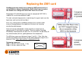
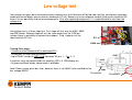
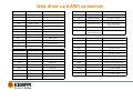
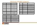
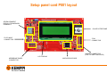
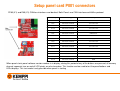
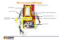
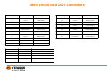
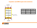
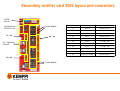
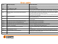
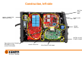
1
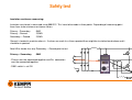
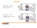
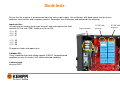
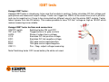
Service manual FastMig Pulse power sources
version 1.1
Released 30.12.2009
Updated 13.01.2010
WARNING!
400VAC 50/60Hz and 570VDC or higher are inside the machine
Before removing any covers or commencing any testing or measurement disconnect
the power source from the mains voltage
Dangerous DC voltage still exist after the removal of the input voltage.
Wait at least one minute for the capacitors to become discharged.
The device may be repaired only by a person legally authorized to perform electric
work.
Electrostatic Discharge
Electrostatic discharge (ESD) is phenomenon that occurs almost everywhere and often. At its most powerful, it is known as
thunder and lightning electrical charges as high as one billion volts can be discharged between clouds or between clouds and
the ground below. This type of electrical discharge cannot occur at normal ground level, of course.
Movement and friction generate static discharges of a few thousand volts in certain conditions. For example, stroking a cat can
generate thousands of volts.
Electronic appliances welding machines included are now designed and manufactured in ways that take into account the ESD
problem. It is only apparent when an appliance is taken apart for servicing. At that time the ground terminal is often
disconnected and sensitive electronic components can be prone to electrostatic discharge. The best way to protect against
ESD when handling electronic cards or microchips is an earth connection. You frequently hear of people who wonder why a
new, unused electronic card works at first and then stops working afterwards. The reason may well be that some of its
components are damaged by ESD. Memory circuits are especially sensitive. It may be that a memory circuit damaged by ESD
breaks down only weeks later. It looks like a software problem but in fact it is a tiny defect in the memory circuit itself.
A simple, effective enough way to protect against ESD is to wear an earth bracelet when handling electronic circuits or cards.
The bracelet is earthed to the frame of the appliance being serviced. An equally important shielding device is an earth pad on
the workbench. Also wearing clothing manufactured from natural fiber (cotton) decreases electrical charging.
All Kemppi factory parts susceptible to ESD (e.g. control cards) are delivered in packaging or pouches that
protect and earth the components. Packets and pouches carry yellow ESD labels. Parts susceptible to ESD
must be kept in their original packages only removed just before installation.
Article taken and abridged from Kemppi PRONEWS
Tools and testing equipments
While repairing Kemppi machines there is no need to have any special hand tools. Most of the work can be done with normal
workshop tools and testing can be done by digital multimeter and Kemppi Multipower or a standard workshop power source.
Hand tools and accessories:
Metric combination wrenches 8-19mm, 28mm
Screwdrivers: flat 0,5 x 3mm and torx T10-T25
Needle-nose pliers
Side cutters
Torque wrench with torx heads
Cable ties
Testing equipments:
Digital multimeter True RMS (800VDC, 600VAC for safe operation)
Regular workshop power source (with 20VAC output) or Kemppi Multipower (22VAC)
PE tester (15-25A e.g. Megger PAT32)
Insulation resistance meter (500VDC, e.g. Megger PAT32)
Useful extra tools:
Kemppi IGBT tester
Digital oscilloscope 10MHz or greater
General service procedure
It is recommended that a systematic method is used on all repair or maintenance work, each repair is a
special case and should be handled as required, but by following a routine, less mistakes and safety issues
will occur. Here is an example of a general routine:
1. Safety test
2. General troubleshooting
3. Static tests
4. Repair work
5. Low voltage test
6. Load bank test
7. Safety test
8. Test welding
Note! Safety test must be done before and after repair, to be sure machine is not possibly dangerous for user
or service man. Remember always use recommended fuse sizes in service workshop equipment to be sure
of safety issues.
Always try to isolate failure to certain blocks. This manual has several tests to make conclusions and to
isolate the problem. Be careful not to make assumptions, because it might lead you to change the wrong
parts.
Safety test
Safety test should be carried out before opening machine or connecting it to the mains power
supply, to protect the service technician.
All the new machines are tested in the factory, but it is recommended to repeat these tests before and after service repair work.
The safety test is divided into two parts, protective earth (PE) conductor continuity and insulation resistance measuring.
PE conductor continuity measuring:
PE continuity is measured between protective earth conductor and machine chassis. Resistance should be less than 100mΩ
(0,1Ω). Below is a calculation to determine the desired test voltage
R = 100mΩ
I = 15 A
U =?
U = R × I = 0,1Ω ×15 A = 1,5V
When using 15A as the measuring current, the voltage should be less
than 1,5V between PE conductor and machine chassis. Then the
resistance must be less than 100mΩ.
Easiest way to measure PE conductivity is to have special tester like
Megger PAT32. It tests conductivity using an input current of 25A, so
voltage should be less that 2,5V.
The protective conductor continuity measuring can be
done with equipment similar to that shown in these
pictures
Safety test
Insulation resistance measuring:
Insulation resistance is measured using 500VDC. This have to be made in three points. Depending of measuring point
there have to be minimum resistance values:
Primary – Secondary
Primary – Ground
Secondary – Ground
5MΩ
2,5MΩ
2,5MΩ
Ground is located in machine chassis. If values are much less than expected there might be insulation break down and it
should be inspected.
Note! Wire feeder has only Secondary – Ground point to test
Primary – Secondary
5MΩ
• Phases must be connected together and Dix connectors
must be connected together.
• S001 switch is set ON
Safety test
Primary – Ground
2,5MΩ
• Phases must be connected together
• S001 switch is set ON
Secondary – Ground
2,5MΩ
• Dix connectors must be connected together
• S001 switch is set ON
General troubleshooting
Always try to get a detailed description of the complaint!
This troubleshooting guide is to remind the service technician, to check the simple things first, a visual
inspection can often help with fault finding. If visual damage can be seen, replace all broken parts. If
everything looks normal, or broken parts are changed, it is recommended, that a low voltage test is carried
out.
Disconnect the machine from the input supply and remove covers, then check:
• Are there any breaks in the cables?
• Are the cables correctly connected?
• Are there any loose components?
• Are mains fuses/circuit breakers OK & correct valves?
• Any signs of burning or arching?
Connect the machine to the mains input supply and check:
• Is there a stable three phase 400VAC input inside the machine?
• Is the machine in shut down mode?
• Are the settings OK?
Diode tests
Ensure that the machine is disconnected from the mains input supply. Use multimeter with diode check function to test
machines input rectifier and secondary rectifier. Remember to test forwards and backwards the following.
Input rectifier:
Use positive test lead to check input terminal side and negative test lead
to check DC link side. S001 switch must be set ON.
• L1 – X1
• L2 – X1
• L3 – X1
• L1 – X3
• L2 – X3
• L3 – X3
Change test leads and repeat tests.
If diodes OK:
There should be threshold voltage approx. 0,5VDC (forward biased
condition) or over the meters limit (reverse biased condition)
If short circuit:
close to 0VDC.
Input terminal
X1 DC link
positive
X3 DC link
negative
Diode tests
Use multimeter with diode check function to test machines input rectifier and secondary rectifier. Remember to test
forwards and backwards the following.
Secondary rectifier:
Use positive test lead to check positive output side and negative test
lead to check four banks of diodes.
• Positive output rail – Bank 1
• Positive output rail – Bank 2
• Positive output rail – Bank 3
• Positive output rail – Bank 4
Change test leads and repeat tests.
There should be threshold voltage approx. 0,335VDC (forward
biased condition) or “over the limit” (OL) (reverse biased
condition)
If meter reads close to 0VDC, diodes are in short circuit.
POSITIVE OUTPUT RAIL
FOUR BANKS OF DIODES
IGBT tests
IGBT module can be tested two different ways. Easiest and fastest is to use DMM to have some info about IGBT
module. Another way is to use Kemppi IGBT tester to have exact data.
IGBT testing by DMM:
To test the modules four IGBTs individually, disconnect the gate leads X3 and X4 from the A001 card, set the DMM to
diode check function, use the chart below.
X4
IGBT number
Positive test lead
Negative test lead
IGBT 1
gate lead X4-1
Z002 X1
IGBT 2
Z002 X3
Gate lead X4-1
IGBT 3
Gate lead X3-3
Z002 X1
IGBT 4
Z002 X3
Gate lead X3-3
The threshold voltage should be approx. 0,335VDC (forward biased)
Reverse the test leads, and repeat the above tests, the meter should read
“over the limit” or “OL” (reversed biased)
X3
IGBT tests
IGBT gate lead testing (set to resistance function):
• Disconnect module gate leads X3 and X4
• Measure twisted paired wires
X4
Meter should read approx. 10kΩ
Simple static test of A001 gate circuit (set to diode function):
• Disconnect module gate leads X3 and X4
Positive test lead
Negative test lead
X4-4
X4-1
X4-6
X4-3
X3-4
X3-1
X3-6
X3-3
Meter should read approx. 0,1VDC.
Reverse the test leads, and repeat the above tests, the meter should read
“over the limit” or “OL”
X3
IGBT tests
Kemppi IGBT tester:
Kemppi IGBT tester is simple way to be sure that module is working. Tester simulates DC link voltage and
gate pulses and measures output voltage. Tester can trigger two IGBTs at the same time (one for positive
and one for negative) so it have to be connected two different ways to test the whole IGBT module. Tester
takes it power from two 9V battery. This makes possible to have “DC link” voltage as high as 18VDC which
makes measuring more reliable.
Kemppi IGBT tester buttons and connectors:
ON/OFF switch
Switches tester ON and OFF
TR1 and TR2:
Trigger buttons for gate controls
LEDS:
Shows if output has a voltage
C1/3:
Emulates DC link positive voltage
E2/2:
Emulates DC link negative voltage
B1/4:
TR1 gate control signal/positive
B2/6:
TR2 gate control signal/negative
C2E1/1:
Pos. / Neg. output voltage measuring
Note! Switching tester OFF saves battery life while not used.
IGBT tests
X1
X3
X4
Kemppi IGBT testing by Kemppi IGBT tester:
• Disconnect X3 and X4 connectors
IGBTs 1 and 2:
• Connect C1/3 to Z002 X1 (DC link positive)
• Connect E2/2 to Z002 X3 (DC link negative)
• Connect B1/4 to X4-4 (IGBT 1 gate control, positive)
• Connect B2/6 to X4-6 (IGBT 2 gate control, negative)
• Connect C2E1/1 to X4-1 (point between IGBT 1 and 2)
IGBTs 3 and 4:
• Keep C1/3 and E2/2 connected as above
• Connect B1/4 to X3-6 (IGBT 3 gate control, positive)
• Connect B2/6 to X3-4 (IGBT 4 gate control, negative)
• Connect C2E1/1 to X4-1 (point between IGBT 3 and 4)
Only when triggering by buttons TR1 and TR2 LEDs should
illuminate.
If LEDs don’t light or are lit without triggering, the IGBT module
may be faulty. Double check connections to be sure.
X3
Replacing the Z001 card
FastMig production family has a soldering IGBT module and it is
not possible to change it separately. Only reliable way to replace
the module is to change the whole Z001 main circuit card.
Electrolube HTC NON-Silicone heat transfer compound EHTC10S is
supplied for use during equipment repair.
The tools and workshop premises used during this type of work must be
kept clean and free from dirt and dust.
Even very small particles (0,050mm) between the surfaces could
increase the gap between the module an the heat sink ,causing
overheating and damage.
Heat sink transfer compound is to be spread in an even layer of
approximately 0,1mm onto the module. Then the module should be
immediately mounted onto the heat sink, this minimizes the possibility of
any contamination (dirt etc.) getting between the components.
The M5 fixing screws are tightened (stage 1) to 0,5 – 2 Nm. After few
minutes the module fixing screws can be finally tightened (stage 2) to a
torque of 3 Nm. Note! Input rectifier is tightened to 2 Nm.
Tightening sequence:
Stage 1: All four screws to 0,5 – 2 Nm
Stage 2: All four screws to 3 Nm
Low voltage test
Low voltage test gives basic information where machine has fault. Machine will be fed from auxiliary transformer secondary
winding to control blocks and via primary winding to DC link. Because of reversed power feeding (and current limited to 5A)
there is lesser possibility to burn more components. Also after replacing components it is recommended to start from low
voltage test.
Low voltage test is a three stage test. First stage will test only the A001, A002
and P001 cards. Second stage will test the same cards and, the CAN bus
voltage (there is possibility to connect wire feeder). Third stage test all the
above and the DC link.
X2
X008
Testing First stage:
• Current must be limited to 5A in workshop PSU
• Disconnect X2 and X008 connectors
• Input 20VAC straight to A001 card connector X2 pins 1 - 2 or 2 - 3.
If machine starts up control cards are working (LED’s lit, P65 display on)
• By pressing Menu button, demo mode is available
Note! Power source gives bus error, because there is no 38VAC to be rectified for the
bus voltage 50VDC
Disconnect
Disconnect
20VAC
Low voltage test
Testing Second state:
• Current must be limited to 5A in a workshop PSU
• Connect only X2 and input 20VAC to connector X2 pins 1-2 or 2-3
• Voltage goes to another secondary coil as 38VAC
• Wire feeder unit can be connected and all setups used
• Wire feeder can be triggered and wire feed speed adjusted
38VAC
If no wire feeder is connected, P65 display show’s “Local loop”.
If machine can start up, control cards and CAN bus is working (check voltage).
Testing Third stage:
• Current must be limited to 5A in a workshop PSU
• Input 20VAC to aux. transformers connector X2 pins 1-2 or 2-3
• Voltage goes thought secondary winding to primary side as 400VAC
• Voltage goes also to another secondary coil as 38VAC (as above)
• Machine starts up and DC link voltage can be measured Z002 X1 and X3
• Note! There can be over 400VDC in DC link!
• Wire feeder unit can be connected and all setups used
Connect
20VAC
38VAC
400VAC
If machine does not start up or current goes to 5A limit, there is probably a short circuit
somewhere in the primary.
Note! Wire feeder can not be triggered, power source takes too much power and
machine shuts down.
Connect
20VAC
Gate driver card A001 layout
POWER SUPPLY
FUSES 2 x 3.15A
IGBT DRIVER
PANEL CONNECTOR
COOLING FAN’S
CONNECTORS
OVERHEAT
PROTECTION
PTC’s
CONNECTORS
SYSTEM BUS
INTERFACE
PROCESSOR CARD A002
CONNECTOR
POWER-ON LED AND
OVERTEMPERATURE LED
CONNECTOR
WATER COOLER
CONNECTOR
Gate driver card A001 LED info
A001 Gate driver card has several LEDs to show basic information of cards functions and states. LEDs H1, H4, H5 and H6 shows if
IGBT can have control signals. LEDs H7 and H8 show if there is feeder unit connected and if data is available in CAN bus. LEDs H2 and
H3 shows if there is needed control voltages from cards own PSU.
H1
H4
H5
H6
IGBT gate pulses
IGBT gate pulses
IGBT gate pulses
IGBT gate pulses
H7 Remote control unit connected
H8 Data communication
H2 +5V
H3 +15V
Gate driver card A001 connectors
Connector/pin
Connector type
Description
Connector/pin
Connector type
Description
X1
Tab terminal 6,3mm
DC-link voltage (+)
X6/1
2-pin wire to board
Switched Fan M001 (-)
X6/2
MATE-N-LOCK2
Fan M001 +24VDC
X7
40-pin box header
Connects gate driver
and processor board
X8
16-pin box header
with locking latches
Panel board connector
X2/1
3-pin wire to board
20V auxiliary voltage ~
X2/2
MATE-N-LOCK
20V auxiliary voltage ground
X2/3
20V auxiliary voltage ~
X3/1
6-pin wire to board
IGBT emitter
X3/2
MATE-N-LOCK
Not Connected
X3/3
IGBT emitter
Connector/pin
Connector type
Description
X3/4
IGBT gate
X9/1
12-pin wire to board
System bus DATA
X3/5
Not Connected
X9/2
MATE-N-LOCK
System bus DATA
X3/6
IGBT gate
X9/3
System bus +50V
Connector/pin
Connector type
Description
X9/4
System bus +50V
X4/1
6-pin wire to board
IGBT emitter
X9/5
System bus +50V
X4/2
MATE-N-LOCK
Not Connected
X9/6
Remote control +5V
X4/3
IGBT emitter
X9/7
Remote control +5V
X4/4
IGBT gate
X9/8
Remote control analog input
X4/5
Not Connected
X9/9
Remote control analog input
X4/6
IGBT gate
X9/10
System bus GND
X9/11
System bus GND
X9/12
System bus GND
X5/1
2-pin wire to board
Switched Fan M002 (-)
X5/2
MATE-N-LOCK2
Fan M002 +24VDC
Gate driver card A001 connectors
Connector/pin
Connector type
Description
X12
Tab terminal 6,3mm
Chassis ground
X13/1
X13/2
2-pin wire to board
MATE-N-LOCK2
PTC, primary
heat sink profile
PTC, primary
heat sink profile
X14/1
2-pin wire to board
PTC,
main transformer
X14/2
MATE-N-LOCK2
PTC,
main transformer
X15/1
2-pin wire to board
PTC, secondary
heat sink profile
X15/2
MATE-N-LOCK2
PTC, secondary
heat sink profile
Connector/pin
Connector type
Description
X17/1
6-pin wire to board
Cooling unit, supply voltage +24V
X17/2
MATE-N-LOCK2
Cooling unit, error signal (0 – active)
X17/3
Cooling unit, GND
X17/4
Cooling unit, analog input
X17/5
Cooling unit, analog input
X17/6
Cooling unit, on/off signal (+5VDC = on)
X18
Plated PCB hole
Chassis ground
Connector/pi
n
Connector type
Description
X16/1
12-pin wire to board
Spare supply voltage +15V
X16/2
MATE-N-LOCK
Auxiliary voltage ground
X16/3
Spare supply voltage +5V
X16/4
Auxiliary voltage ground
X16/5
Not connected
X16/6
Auxiliary voltage ground
X16/7
Over temperature LED +5VDC
X16/8
Over temperature LED switched
Gnd
X16/9
Power ON LED switched +5VDC
X16/10
Power ON LED Gnd
X16/11
Spare supply voltage +24V
X16/12
Auxiliary voltage ground
Processor card A002 layout
POWER SUPPLY
PRIMARY CURRENT,
SECONDARY VOLTAGE
AND CURRENT
MEASUREMENT
CIRCUITRY
PRIMARY CURRENT
TRANSFORMER AND
MACHINE SIZE JUMPER
CONNECTOR
GATE DRIVER CARD A001
CONNECTOR
POWER
SUPPLY
JTAG
CONNECTOR
SECONDARY VOLTAGE
AND CURRENT (SHUNT)
CONNECTOR
MICROCONTROLLER
REAL TIME CLOCK
BATTERY CR2032
FPGA
Processor card A002 LED info
A002 processor card also has LEDs for easy card level checking. H9 – H14 show different voltages in card. Led
H8 shows if FBGA configuration is executed successfully (LED should illuminate). H1 shows microcontrollers
operation state and H2 – H3 shows if there is activity in data communication lines.
H12 +5V
(analog)
H9 +15V
H10 +5.3V
H11 +1.2V
H13 +2.5V
H14 +3.3V
H8 FPGA Configuration
H1 Microcontroller state
H2, H3 Data communication
Processor card A002 connectors
Connector/pin
Connector type
Description
Connector/pin
Connector type
Description
X1
20-pin box
header
JTAG
(production programming)
X11/1
6-pin wire to
board
Not connected
X11/2
MATE-N-LOCK2
Spare A/D, not connected
X3
40-pin box
header
Connects gate driver and
processor board
X9/1
6-pin wire to
board
Current transformer (ac)
X9/2
MATE-N-LOCK2
Machine size jumper J1
X9/3
Machine size jumper J2
X9/4
Current transformer (ac)
X9/5
Machine size jumper J1
X9/6
Machine size jumper J2
X11/3
Shunt (+)
X11/4
Secondary voltage (+)
X11/5
Not connected
X11/6
GND, Shunt (-)
G1
2032 battery
holder
RTC battery
Setup panel card P001 layout
SEVEN SEGMENT
DISPLAY FOR MEMORY
CHANNELS
PULSE POTENTIOMETER
FLATCABLE
CONNECTOR
JTAG
CONNECTOR
JUMPER CONNECTOR
(FOR FUTURE PURPOSES)
LCD DISPLAY
MEMBRANE PANEL
CONNECTOR
MICROPROCESSOR
Setup panel card P001 connectors
PF65 (X1) and P65 (X1) CAN bus interfaces are identical. Both Panels use CAN interface and KeBus protocol.
Connector/pin
Connector type
Description
X1/1
Pin header, 2.54mm
Not connected
X1/2
Pin header, 2.54mm
Not connected
X1/3
Pin header, 2.54mm
Not connected
X11/4
Pin header, 2.54mm
Not connected
X1/5
Pin header, 2.54mm
WF number
X1/6
Pin header, 2.54mm
CAN transfer
X1/7
Pin header, 2.54mm
GND
X1/8
Pin header, 2.54mm
CAN receive
X1/9
Pin header, 2.54mm
Not connected
X1/10
Pin header, 2.54mm
Not connected
X1/11
Pin header, 2.54mm
Not connected
X1/12
Pin header, 2.54mm
Not connected
X1/13
Pin header, 2.54mm
Not connected
X1/14
Pin header, 2.54mm
Not connected
X1/15
Pin header, 2.54mm
+5VDC
X1/16
Pin header, 2.54mm
GND
When panel starts panel software version number in in display, during this period of any of the buttons are pressed, all memory
channel segments turn on and all LCD pixels are also turned on. This function can be used to test the panel buttons and
LEDs/displays. This test mode is only possible when panel is starting
Main circuit card Z001 layout
Z002 CARD CONNECTIONS
IGBT MODULE
INPUT RECTIFIER
PRIMARY CURRENT TRANSFORMER
Z002 CARD CONNECTIONS
GATE CONTROL
CONNECTORS
TRANSIENT SUPPRESSION DIODE
EMI FILTER
Main circuit card Z001 connectors
Connector/pin
Connector type
Description
Connector/pin
Connector type
Description
X1
Bolt on
Main switch
X16
Bolt on
Primary choke
X2
Bolt on
Main switch
X17
Bolt on
Primary choke
X3
Bolt on
Main switch
X18
Bolt on
DC-link voltage (+)
X4
Plated PCB hole
Chassis ground
X19
Bolt on
DC-link voltage (+)
X5
Plated PCB hole
Chassis ground
X20
Bolt on
DC-link voltage (-)
X29
Soldered wire
Chassis ground
X21
Bolt on
DC-link voltage (-)
X6
Bolt on
Main transformer
X31
Soldered wire
DC-link voltage (+)
X7
Bolt on
Main transformer
X8-X15
Soldered wire
IGBT gates and emitters
Connector/pin
Connector type
Description
X36
Soldered wire
Current transformer secondary
X37
Soldered wire
Current transformer secondary
X40
Soldered wire
400VAC Aux. transformer
X41
Soldered wire
400VAC to Aux. transformer
Capacitor card Z002 layout and connectors
DISCHARGE
RESISTORS
X1
X3
DC – LINK
CAPACITORS
X2
X4
DISCHARGE
RESISTORS
Connector/pin
Connector type
Description
X1
Bold on
DC-link voltage (+)
X2
Bold on
DC-link voltage (+)
X3
Bold on
DC-link voltage (-)
X4
Bold on
DC-link voltage (-)
Secondary rectifier card Z003 layout and connectors
FILTER
CIRCUIT
TIG INGNITION
PROTECTION
X1 – X2
DIODE BANKS
X5 – X8
Connector/pin
Connector type
Description
X1
Bold on
Main transformer
X2
Bold on
Main transformer
X3
Bold on
Main transformer
X4
Bold on
Main transformer
Bold on
RC – DAMPING
CIRCUIT
X3 – X4
DIODE BANKS
X5
Bold on
Secondary choke
X6
Bold on
Secondary choke
X7
Bold on
Secondary choke
X8
Bold on
Secondary choke
X9
Tab terminal 6,3mm
Main transformer
Other tests
PTC CONNECTORS
FAN CONNECTORS
Here are several useful tests not mentioned before.
Machines three PTCs in connectors X13 – X15:
• PTCs are serial wired and any of them can affect thermal alert
• Resistance should be 55 - 70Ω
• Values measured in 20 Celsius degrees and may vary depending environment
temperature
• If machine is warmed up values may vary
• Broken PTC has mostly hundreds of kilo ohms or no value at all
Cooling fans:
• Cooling fans operating voltage is 24VDC (max. current 458mA)
• When cooling fans start, ground is switched
If cooling fans are not working, they might be short circuited or A001 card has failure in
control logic.
Note! There is delay in cooling fan start up.
CAN bus voltage 0VDC
• Check if there is aux. voltage 38VAC to aux rectifier G003
• Check if there is CAN bus voltage 50VDC in rectifiers output
• Check if there is burned fuse in back plate fuse socket (6,3A)
DC
PLUS
AC
AC
DC
MINUS
CAN bus voltage
rectifier
Load bank test
Load back test is used not only to simulate welding but also to check voltage/current characteristics. Load bank can be
passive load with switchable power resistors or active with selectable voltage/current curves. If using passive load bank
a multimeter is used for voltage and clamp meter for current measuring. Some passive loads has integrated meter for
easier testing. Active loads have mostly meters because of their special construction (its control electronics needs
values to adjust active load).
To be sure load bank is adjusted correctly, a calculation is required for voltage or current to have desired nominal
curve. Constant voltage (e.g. MIG/MAG) and constant current (MMA) have different voltage/current values and they
can be calculated from following formulas.
CC (MMA machines) curve’s secondary voltage can be calculated when certain current is set:
U 2 = 0,04 × I 2 + 20
CV (MIG/MAG machines) curve’s secondary current can be calculated when certain voltage is set:
I2 =
U 2 − 14
0,05
Voltage/current have to be set for nominal curve, correct output power. E.g. when making PTC test there must be right
values to meet duty cycle specified in technical specification.
Most useful tests to be made with a load bank are to check maximum and minimum current and to check if machines
voltage/current adjustments and control electronics work.
Load bank test
Fastmig pulse power source can be tested without wire feeder in local loop mode. In local loop mode it is possible to
have a secondary current up to 100A. To adjust current, remote controller have to be connected
Note! Local loop mode does not include MMA nominal curve so it is not possible to weld by MMA
Example 1: Constant current test (local loop mode)
• Turn the machines main switch OFF
• Connect machine to load bank
• Turn the machines main switch ON
• Connect remote controller to power source
• In panel P65 can be seen title “Local loop”
• Add some load to load bank
• When current starts to flow, raise current to desired level (this example uses maximum value 100A)
• Be fast when increasing load, there can exist arc inside the load bank switches
• Measure current by clamp meter and voltage by DMM
• Values can be seen also in panel P65
Current should be 100A and voltage can be calculated from following equation:
I 2 = 100 A
U 2 = 0,04 × I 2 + 20
= 0,04 ×100 A + 20 = 4 + 20 = 24V
To get required voltage increase or decrease load in the load bank. Before disconnecting the load, decrease machine
current to minimum to avoid unnecessary arc inside the load bank switches.
Load bank test
To make MIG/MAG load bank test for Fastmig Pulse, wire feeder must be connected to the power source.
Example 2: Constant voltage test (MIG/MAG)
• Turn the machines main switch OFF
• Connect machine to load bank
• Turn the machines main switch ON, be sure machine start is OFF (open)
• Add some load to load bank
• Adjust machine voltage to desired level (this example uses 22V)
• Start the machine
• Measure current by clamp meter and voltage by DMM
• Values can be seen also in panels P65 and PF65
Now voltage should be 22V and current can be calculated from following equation:
U 2 = 22V
U 2 − 14
0,05
22V − 14
8
=
=
= 160 A
0,05
0,05
I2 =
To get the required current increase or decrease load in the load bank. Before disconnecting the load, put machine
start to OFF to avoid unnecessary arc inside the load bank switches.
Error codes
Error
Problem description
Solution description
Err 1
Power source not calibrated or calibration data cannot be
read
Restart power source, if the problem continues after multiple startups, check the power
source control cards.
Err 3
Over voltage, mains supply
Check the main voltage.
Err 4
Over heat, power source
Do not shut down the machine, cooling fans will cool the machine. Check the ventilation.
If cooling fans are not running, check the power source connections and voltages.
Err 5
Auxiliary voltage +15VDC too low (control card led H9
+15VDC)
Main supply voltage is too low or aux supply faulty, check the main/aux supplies. Can
show up also if one of the mains phases is missing.
Note! Only one of the three phases can affect this error if missing (one where aux
transformer is NOT connected).
Err 8
FPGA not configured
Restart the power source, if the problem continues after multiple startups check the
power source control cards.
Err 27
Water cooler error
Check the water cooler connections and functions. For more details check the cooler
service manual.
Err 42
WF Motor over current warning, delayed fault at 3,5A
Check the gun and the consumable parts.
Err 43
WF Motor over current error, delayed lock at 5A
Check the gun and the consumable parts.
Err 45
Gas guard alert (only if gas guard connected and activated)
Check the shielding gas, gas guard and all the connections.
Err 50
Function is not activated
If function is required, please order proper license.
Err 62
Power source not connected or not identified
Check the intermediate cable. Feeder is powered up but it can not identify the power
source.
Err 81
Welding program not found
If welding program is required, please order proper welding program and license.
MEM ERR
Error while reading or writing to memory
Machine can not write to feeder memory card, check the cables and connections,
possibly broken control/memory card.
NO BUS
Panel can not connect to the CAN bus
Check the flat cables. Check the panels
Construction, right side
PRIMARY
CHOKE
AUXLIARY
TRANSFORMER
Z003
SECONDARY
RECTIFIER
DIODES
MAIN
TRANSFORMER
SECONDARY
CHOKE
SECONDARY EMC
FILTER
Construction, left side
IGBT DRIVER
CARD
A001
MAINS CONNECTOR
AND VARISTORS
PANEL CARD
P001
MAINS
SWITCH
WATER COOLER
POWER CONNECTOR
Z001 MAIN CIRCUIT BOARD
AND Z002 DC-LINK
CAPACITOR BOARD
SHUNT RESISTOR
PROCESSOR CARD A002