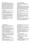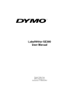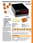
1
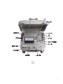
HR-33T Dew Point Microvoltmeter
Instruction/Service Manual
© 1978, 1986, 2001 Wescor, Inc
M2820-1
Wescor, Inc
459 South Main Street
Logan, UT 84321 USA
Phone: 435-752-6011
Toll Free: 800-453-2725
Fax: 435-752-4127
Email: [email protected]
Email Service: [email protected]
CONTENTS
SECTION 1 – INSTRUMENT SPECIFICATIONS . . . . . . . . . . . . . . . . . . . . . . . . . . . . . . . . . . . . . . . . . . . . 3
SECTION 2 – BASIC OPERATING PROCEDURE . . . . . . . . . . . . . . . . . . . . . . . . . . . . . . . . . . . . . . . . . . .
2.1 – Dew Point Mode . . . . . . . . . . . . . . . . . . . . . . . . . . . . . . . . . . . . . . . . . . . . . . . . . . . . . . . . . . .
2.2 – Psychrometric Mode . . . . . . . . . . . . . . . . . . . . . . . . . . . . . . . . . . . . . . . . . . . . . . . . . . . . . . . .
2.3 – Combined Dew Point and Psychrometric Mode . . . . . . . . . . . . . . . . . . . . . . . . . . . . . . . . . . . .
2.4 – Temperature Measurements . . . . . . . . . . . . . . . . . . . . . . . . . . . . . . . . . . . . . . . . . . . . . . . . . . .
5
5
6
6
8
SECTION 3 – ADDITIONAL OPERATING INFORMATION . . . . . . . . . . . . . . . . . . . . . . . . . . . . . . . . . .
3.1 – Av Set Adjustment . . . . . . . . . . . . . . . . . . . . . . . . . . . . . . . . . . . . . . . . . . . . . . . . . . . . . . . . .
3.2 – Thermal and Vapor Equilibration . . . . . . . . . . . . . . . . . . . . . . . . . . . . . . . . . . . . . . . . . . . . .
3.3 – Effect of Zero Drift on Reading . . . . . . . . . . . . . . . . . . . . . . . . . . . . . . . . . . . . . . . . . . . . . . .
3.4 – Ancillary Instrument Functions . . . . . . . . . . . . . . . . . . . . . . . . . . . . . . . . . . . . . . . . . . . . . . .
3.5 – Av Versus Temperature . . . . . . . . . . . . . . . . . . . . . . . . . . . . . . . . . . . . . . . . . . . . . . . . . . . . .
11
11
12
13
13
13
SECTION 4 – THEORY OF OPERATION . . . . . . . . . . . . . . . . . . . . . . . . . . . . . . . . . . . . . . . . . . . . . . . . .
4.1 – Thermocouple Cooling Coefficient . . . . . . . . . . . . . . . . . . . . . . . . . . . . . . . . . . . . . . . . . . . .
4.2 – Psychrometric Method . . . . . . . . . . . . . . . . . . . . . . . . . . . . . . . . . . . . . . . . . . . . . . . . . . . . . .
4.3 – Dew Point Method . . . . . . . . . . . . . . . . . . . . . . . . . . . . . . . . . . . . . . . . . . . . . . . . . . . . . . . . .
4.4 – HR-33T Dew Point System . . . . . . . . . . . . . . . . . . . . . . . . . . . . . . . . . . . . . . . . . . . . . . . . . . .
4.5 – Effect of Ambient Temperature . . . . . . . . . . . . . . . . . . . . . . . . . . . . . . . . . . . . . . . . . . . . . . .
15
15
17
17
18
20
SECTION 5 – ELECTRONICS . . . . . . . . . . . . . . . . . . . . . . . . . . . . . . . . . . . . . . . . . . . . . . . . . . . . . . . . . . 23
SECTION 6 – MAINTENANCE . . . . . . . . . . . . . . . . . . . . . . . . . . . . . . . . . . . . . . . . . . . . . . . . . . . . . . . . . 27
6.1 – General Maintenance . . . . . . . . . . . . . . . . . . . . . . . . . . . . . . . . . . . . . . . . . . . . . . . . . . . . . . 27
6.2 – Batteries . . . . . . . . . . . . . . . . . . . . . . . . . . . . . . . . . . . . . . . . . . . . . . . . . . . . . . . . . . . . . . . . 27
SECTION 7 – TROUBLESHOOTING . . . . . . . . . . . . . . . . . . . . . . . . . . . . . . . . . . . . . . . . . . . . . . . . . . . . 29
SECTION 8 – PARTS LIST . . . . . . . . . . . . . . . . . . . . . . . . . . . . . . . . . . . . . . . . . . . . . . . . . . . . . . . . . . . . 39
L
HR-33T
Figure 1
1
L
2
SECTION 1 – INSTRUMENT SPECIFICATIONS
Standard Power Supplies
HR-33T: 5103A Modular Battery Pack (included with instrument).
Batteries: Four Eveready type 522 or equivalent. Battery Life: 10
hours nominal.
HR-33T-R: 5112 Rechargeable Battery Pack (included with
instrument). Consists of 30 Nicad batteries in a case which is
interchangeable with the 5103A Battery Pack or the AC power
supplies. The HR-33T-R will operate approximately 20 hours per
charge.
Optional AC Power Supplies
Model 5106: 115V 50-60 Hz.
Model 5109: 230V 50-60 Hz.
Controls
ON/OFF (power supply module)
ZERO OFFSET COARSE
ZERO OFFSET FINE
RANGE
FUNCTION
Av SET
Av (Read)
/C/µV (temperature/microvolts)
Ranges
10, 30, 100, and 300 µvolts full scale plus positive and negative
battery voltage, temperature 0/C to 30/C, 0-100/C (with accuracy as
specified below)
Functions
HEAT, INPUT SHORT, READ, COOL, DEW POINT
Accuracy
± 1% of full scale-recorder output
± 2% of full scale-panel meter
Temperature ± 0.5/C from 0/C to 40/C (refer to Figure 3)
Zero Drift
Less than 0.5 µvolts per 24 hours
Less than 0.1 µvolts per 1/C
Noise
Less than 0.1 µvolts p-p
Input Impedance
100 ohms or less (higher impedances will degrade accuracy)
Rise Times
2 seconds (10% - 90%)
Zero Suppression
± 75 µvolts
Recorder Output
10 volts full scale (10mA)
Connectors
SUREFAST™ bulkhead connector
Binding Posts
(constantan binding post for reference junction)
External Dimensions
23 cm x 30 cm x 13 cm
Weight
3.3 kg with batteries
3
4
L
5
SECTION 2 – BASIC OPERATING PROCEDURE
The HR-33T permits water potential determination with a variety of sensors in either the dew point or the
psychrometric mode. Both methods of measurement, after proper calibration, should give the same water
potential. The dew point method of water potential measurement is affected much less by changes in ambient
temperature than the psychrometric method. The sensitivity coefficient of the dew point method is approximately
twice that of the psychrometric method. For these reasons, the dew point method is often preferred. Either method
may at different times appear to be the better choice, depending upon the circumstances and conditions of a
particular experiment. Procedures for both methods are detailed in the following.
2.1 – Dew Point Mode
Be sure that the battery pack or the power supply is supplying the proper voltage (see section 6).
The following step-by-step procedure will enable you to obtain consistent and meaningful results from any type
of thermocouple psychrometer, including thermocouples mounted in sample chambers.
1.
Always set the FUNCTION switch on INPUT SHORT while connecting or disconnecting to the input
terminals. If the sensor is equipped with a SUREFAST™ connector, plug the connector into the
SUREFAST receptacle on the front panel. If the sensor does not have a connector, the leads should be
connected to the binding posts. The wire from the chromel side of the hygrometer/psychrometer should
be connected to the black binding post and the wire from the constantan side of the
hygrometer/psychrometer should be connected to the red binding post. The constantan wire from the
temperature measurement thermocouple should be connected to the blue binding post. On Wescor
hygrometer/psychrometers, the copper lead from the temperature measurement thermocouple is also
connected to the constantan side of the hygrometer/psychrometer thermocouple. If a sensor is used
which has these two leads separate, both should be connected to the red post.
The temperature measurement thermocouple can be connected at the same time as the psychrometer.
Temperature measurements can be made by moving the C//µV switch to the C/ position as explained
in Paragraph 2.4.
2.
6
Determine and set “Av” as follows:
(If “Av” for the sensor to be used is known, adjust the Av SET knob while depressing the Av switch until
the meter is at the desired value).
a.
Allow the thermocouple to equilibrate in a dry, isothermal, surrounding (dew point depression >
1/C). If the sensor is a C-52 Sample Chamber, it is sufficient to empty and dry the sample
chamber by wiping it with a kimwipe. Room air is usually sufficiently dry. Soil psychrometers
or sample chambers which rely upon a waterbath or an insulated box for thermal stability must
be air dried and thermally insulated while Av is determined.
b.
With the FUNCTION switch in the READ position and the RANGE switch set to 30 µvolts, adjust
the ZERO OFFSET control to bring the meter reading to zero. It is necessary to accurately zero
the meter before determining Av.
c.
Rotate the FUNCTION switch to cool for a few seconds, then to DEW POINT. Depending upon
the position of the Av set knob, the meter will tend to (1) fall back toward zero, (2) hold steady,
or (3) climb upscale. Rotate Av SET until the meter holds relatively steady and the reading is
between 15 and 30 on the bottom scale. (If the needle is rising or pegged upscale, rotate the
control clockwise).
d.
When the Av button is depressed, the meter will give a reading proportional to the position of the
Av SET control. The numerical value of the reading on the 100 µvolt scale is the cooling
coefficient, Av, of the thermocouple being used. (See Section 4, Theory of Operation).
3.
If the thermocouple is in a sample chamber, insert the sample to be tested and allow sufficient time for
thermal and vapor equilibration. If using a soil psychrometer or a similar sensor, allow time for
equilibration after installation (Paragraph 3.2).
4.
With the RANGE switch set to the anticipated range and the FUNCTION switch on READ, bring the
meter reading to zero by adjusting the ZERO OFFSET control.
5.
Rotate the FUNCTION switch to COOL long enough to ensure that water has condensed on the
junction. Cooling times required will vary from 5 seconds or less for very wet samples to 30 seconds
or more for dry samples. Once the necessary cooling time has been determined for a given water
potential range and sample type, this time should be used for all measurements within that range,
including calibration measurements.
6.
The temperature of the thermocouple will fall below the dew point temperature during COOL
(assuming the sample is within the measurement range). When switched to DEW POINT, the
temperature will converge to the dew point. The e.m.f. produced by the temperature difference between
the junction at the dew point temperature and the ambient temperature is a linear function of the water
potential. The proportionality constant is approximately -0.75 µvolts bar-1. Within the normal range
of temperatures encountered in water potential measurements, little, if any, correction for ambient
temperature is required. However, it is necessary to maintain the proper Av setting, as explained in
Paragraph 3.5.
2.2 – Psychrometric Mode
The psychrometric mode does not require the determination or setting of Av. To use the HR-33T in the
psychrometric mode, follow the procedure outlined in Paragraph 2.1 through step 5, omitting step 2. After cooling
the junction (step 5), rotate the FUNCTION switch to READ. The meter will indicate a “plateau” signal before
falling to zero. The proportionality constant for psychrometric determination of water potential is approximately
-0.47 µvolts bar-1. The microvolt output divided by this number can be used for rough approximations of water
potential. The temperature correction given below must be used if the temperature is different from 25/C. More
accurate measurements can be obtained by individually calibrating each psychrometer.
A correction for the temperature of the thermocouple can be made using the relationship:
CORRECTED READING = READING / (0.325 + 0.027T)
where T is in degrees Celsius.
2.3 – Combined Dew Point and Psychrometric Mode
Combined dew point and psychrometric measurement is sometimes useful. This can be accomplished by switching
the FUNCTION switch from DEW POINT to READ upon completion of the dew point measurement. The plateau
should be identical to the plateau obtained using the psychrometric mode for the same cooling time. If the plateau
is wider, then water has been added to the thermocouple during the dew point measurement period. If the plateau
is narrower, then water has evaporated during the dew point measurement period. A strip chart recorder should
be employed for this evaluation.
The combined mode permits Av to be experimentally determined under wet thermocouple conditions. The value
of Av must be adjusted until the duration of the plateau is the same as in psychrometric measurement. In readjusting Av, remember that increasing the Av setting decreases the cooling of the thermocouple which will
decrease the width of the plateau.
7
Figure 2 shows the output for each of the three modes of operation presented above. The recordings were made
with a 0.5514 molal NaCl solution in a C-52 Sample Chamber. The psychrometric output for all psychrometers
should be between -0.34 µvolts bar-1 and -0.55 µvolts bar-1 at 25/C.
8
Output For Dew Point, Psychrometric, and Combined Modes
Figure 2
9
2.4 – Temperature Measurements
Use the following procedure to measure temperature with a copper-constantan thermocouple.
1.
Connect the hygrometer/psychrometer using the SUREFAST™ connector if it is so equipped. If a
SUREFAST™ connector is not provided on the sensor, connect the constantan wire to the blue binding
post and the copper wire to the red binding post. It is not necessary to disconnect the
hygrometer/psychrometer sensor leads while making temperature measurements nor is it necessary to
disconnect the temperature measurement thermocouple while making psychrometer measurements.
2.
Set the C//µV switch to C/ and the RANGE switch to 30 for measurement of temperatures between 0/
and 30/ Celsius. Above 30/, use the 100 scale.
3.
Read the temperature in degrees Celsius directly from the meter.
For optimum accuracy, correct the reading using Figure 3.
10
11
Temperature Correction Curve
Figure 3
L
12
SECTION 3 – ADDITIONAL OPERATING INFORMATION
The measurement of water potential using the dew point method is relatively straightforward and eliminates errors
that might otherwise occur in reading the “plateau” signal from a thermocouple using the wet bulb/dry bulb
temperature comparison, or psychrometric method. Nevertheless, while the resulting output from the dew point
meter is less subject to interpretive evaluation, the electronic process by which this output is derived from the
thermocouple is somewhat more involved than with the psychrometric method. It is therefore recommended that
the operator familiarize himself with the principles employed to obtain the dew point reading, as reviewed here
and in Section 4, Theory of Operation, in order that he will have a better understanding of the overall operation
of the instrument and the results obtained. Inherent limitations in the electronic switching circuitry prevent the
instrument from being used in the dew point mode for water potential readings between zero and -1 bar
(approximately 0.75 µvolts).
3.1 – Av Set Adjustment
The dew point method requires that the electronic gain of the duty cycle control circuitry be matched to the cooling
coefficient (Av) of the thermocouple being used. This operation is easily performed using the procedure in
Paragraph 2.1, step 2, which allows the numerical value of Av to be read on the meter. The alternative procedure
described in Paragraph 2.3 may also be used. This gain-matching procedure is essential, since it ensures the
energy-balance condition that will cause the junction temperature to converge to the dew point. If, during the
matching procedure, Av is set so that the meter drifts downward, then while a dew point reading with a wet
thermocouple is being taken, water slowly evaporates from the junction. Conversely, if Av is such that the meter
drifts upward, then the junction will slowly accumulate water. In other words, failure to correctly adjust Av SET
to match the Av of the thermocouple being used will result in the thermocouple being held at a temperature slightly
above or slightly below the dew point. If the junction gradually loses its water until it is dry, then the reading will
become meaningless and decay toward zero.
The cooling coefficient determines the ultimate limit of the thermocouple’s range in measuring water potential
since it represents the maximum temperature depression that can be reached by the junction through Peltier
cooling. If the dew point is below this temperature, no measurement can be made in the dew point mode since
it will not be possible to condense water from the sample onto the junction.
For example, if a given junction has Av = 50 µvolts, the lowest potential that can be measured by the junction will
be
50 µvolts
= -66.6 bars
-0.75 µvolts bar-1
Using the psychrometric method, this same junction would produce a maximum signal of approximately 31
µvolts.1
Wescor junctions typically exhibit cooling coefficients of 50 to 80 µvolts, with some units as low as 40 µvolts or
as high as 90 µvolts.2
1
Researchers have reported measurements as low as -3000 bars using a sample exchange
technique in a Wescor Sample Chamber, but this technique can only be employed in conjunction with the
psychrometric method.
Wescor Soil Psychrometers are individually tested and labeled for cooling coefficient, Av. A
strip chart recording showing the psychrometric response to a 0.55 molal NaCl calibration solution is
included with each sensor.
2
13
3.2 – Thermal and Vapor Equilibration
Thermal equilibration can be easily determined by comparing the reading on INPUT SHORT and on READ. The
difference between these two readings represents the difference between the junction temperature and the
temperature at the head of the psychrometer chamber where the chromel and constantan wires fasten to the
connecting pins. The offset should be less than 3 µvolts for meaningful measurements. Higher offsets are
evidence of excessive thermal gradients (Section 7).
Vapor equilibration can occur very rapidly for a sample chamber containing a solution (often less than one
minute). For a ceramic cup in a calibration solution, equilibration may take one or two hours. For ceramic cups
buried in soil, it is necessary that the disturbed soil come to equilibrium with the surrounding soil. It is advisable
to allow 24 hours after installing soil psychrometers before reading the water potential.
The equilibration time for in situ measurement of water potential of leaves with the L-51 or L-51A Leaf
Psychrometers varies with the type of leaf being measured and the conditions of measurement. Some leaves
equilibrate in 15 minutes or less but others may require several hours.
Repeatable water potential readings indicate that equilibration has occurred. Care must be taken that the period
between measurements is long enough to detect small changes, especially where long equilibration times are
involved.
14
3.3 – Effect of Zero Drift on Reading
Given the condition of water condensed on the junction at the dew point temperature, the direct reading of the
instrument in dew point mode will continue indefinitely. However, the accuracy of the reading will be directly
affected by any thermally induced zero offset that occurs in the thermocouple or intermediary connecting points,
or in the instrument itself. Zero drift in the instrument will normally be negligible, but other effects may become
substantial. Therefore, sustained continuous readings over several minutes in duration should not be relied upon
for accuracy unless extreme care has been taken to allow complete temperature equilibration and unless ambient
temperature variations and thermal gradients have been eliminated.
3.4 – Ancillary Instrument Functions
In addition to the operational functions used to measure water potential as described in Section 2, the HR-33T also
features three additional functions that are incorporated in the RANGE switch and the FUNCTION switch:
HEAT
supplies heating current to the
thermocouple to dry the junction when
necessary.
+BATT
measures internal battery voltage
-BATT
(full scale = 30 volts)
3.5 – Av Versus Temperature
It has been found, both theoretically and empirically, that Av changes by a factor of 0.7 µvolts/°C with Wescor
Psychrometers. Av for temperatures other than the temperature at which Av was measured is given by the formula:
Av,T1 = 0.7(T1 – T0) + Av,T0
where
Av,T1 is the value of Av at the new temperature (T1), and
Av,T0 is the value of Av at the temperature of measurement (T0).
An example of such a correction is as follows:
Given:
Av at 25/C = 55 µvolts
T = 12/C
Av at 12/C = 0.7(12 – 25) + 55 = 45.9 µvolts
For maximum accuracy, Av should be readjusted to the correct value whenever operating at temperatures different
from T0.
15
L
16
SECTION 4 – THEORY OF OPERATION
4.1 – Thermocouple Cooling Coefficient
In a thermocouple consisting of substances a and b, a temperature difference )T between the two junctions will
cause a thermoelectric e.m.f., E, to be set up between the junctions. The magnitude and direction of E is
determined by the thermoelectric properties of the two substances and is given by
E = Pab)T
(1)
where Pab is the sensitivity of the thermocouple in volts/degree.
When a current, I, is caused to flow through the junction in the direction of its thermoelectric e.m.f., the junction
is cooled by an amount proportional to the current. This is known as the Peltier Effect after Peltier who discovered
it in 1834.
dWp
= -AabI
(2)
dt
dWp'dt is the rate of energy transfer. The coefficient Aab is known as the Peltier Coefficient. For very small
currents, a linear relationship exists between the thermoelectric e.m.f. and Peltier cooling; the coefficients Pab and
Aab are related by the equation 3
Aab = T Pab
(3)
where T is the absolute temperature.
Equation (2) may lead one to believe that the junction can be cooled to any desired temperature simply by
providing a sufficient amount of cooling current. At higher values of I, however, this simple relationship does not
hold true inasmuch as the current passing through the junction not only cools by the Peltier Effect, but heats the
junction as a result of the resistance. Equation (2) must therefore be modified to account for this effect such that
dWp
= -AabI + RI2
(4)
dt
3
Smith, Jones, and Chasmar, “The Detection and Measurement of Infra-Red Radiation,” (Oxford
University Press, 1960) p. 62.
17
where R is the electrical resistance of the junction and thermocouple lead wires in the immediate vicinity of the
junction. The second, or heating, term of the equation is negligible at small values of I, but because the heating
effect increases with the square of I, it rapidly becomes the dominant factor in the equation. Thus, in thermocouple
psychrometers, there is an optimum value of cooling current that will produce maximum temperature depression,
beyond which a further increase in current will actually reduce the cooling effect. Furthermore, microscopic
differences in the geometry and alloy makeup of the junctions influence the value of R and hence the net cooling
effect. Thus, while the thermocouple voltage - temperature sensitivity, Pab, and the Peltier Coefficient, Aab, will
be identical in every junction made from the same two materials, the maximum cooling capability of a junction
will vary somewhat from one junction to the next.
When the temperature of the junction is depressed by means of Peltier cooling, heat will begin to flow into it from
its surroundings. This transfer of energy will limit the maximum realizable temperature depression, depending
upon numerous factors including chamber geometry, volume, and materials. When these factors are fixed,
however, the maximum realizable temperature depression of the junction is also fixed. This maximum
temperature depression is of concern in thermocouple psychrometry, and of particular interest where the dew point
method is used.
From the foregoing, it is clear that the Peltier Coefficient, Aab, does not, by itself, determine the maximum
temperature depression of the junction. For our purposes, therefore, we shall define a slightly different coefficient
which we shall call the cooling coefficient. It shall be a characteristic parameter of a given thermocouple
psychrometer, representing its maximum junction temperature depression resulting from the passage of a
nominally optimum cooling current. Since the temperature of the junction is directly related to its thermoelectric
e.m.f., the cooling coefficient will be expressed in microvolts (this is in harmony with the Peltier Coefficient
which, as defined above, also has units of Watts-Ampere, or Volts).
DEFINITION: The cooling coefficient Av, for a given thermocouple psychrometer is defined as the
differential e.m.f. in microvolts that results from the passage of a specified nominally optimum cooling
current through the junction at a specified ambient temperature.
Stated mathematically: Av = Pab)Tm
(5)
where )Tm is the temperature differential that results from the given current. The measurement of Av must be
performed in such a way that the differential e.m.f. is measured immediately after cessation of cooling current
flow, and is completely independent of any consequential effects of the current other than the temperature
depression of the junction. These requirements are fulfilled in the HR-33T.
Statistical data on a large number of Wescor Thermocouple Psychrometers have shown that the optimum cooling
current is typically 8.0 milliamperes. This value of cooling current is standard in the HR-33T Dew Point
Microvoltmeter (RMS current = 8 mA at 95% duty cycle).
18
4.2 – Psychrometric Method
Thermocouple psychrometers provide a measurement of water potential in situ or in sample chambers through
their ability to sense the relative humidity of their environment, this parameter being linearly related to water
potential within the range from 0 to approximately &70 bars. With the psychrometric method, the junction is
cooled by the passage of an electrical current through it (Peltier Effect) to a temperature below the dew pont, thus
causing pure water to condense upon the junction. Having accomplished this, the cooling current is discontinued,
and the condensed water allowed to evaporate from the junction back into the surrounding atmosphere. The
evaporating water draws heat from the junction (heat of vaporization), depressing the temperature of the junction
from that of the surrounding air temperature. The magnitude of the temperature depression depends upon the
relative humidity and the temperature of the surrounding air; the drier (and warmer) the air, the faster the
evaporation rate and the greater the depression. The temperature of the junction is measured by electrical means
prior to cooling and during evaporation. The differential temperature of the junction is an explicit function of the
relative humidity and hence of the water potential in the media being measured.4 Thermocouple psychrometers
have a typical responsivity near 0.47 µvolts bar-1 at 25°C. Because the effects of temperature must be removed
from the measurement, a correction for ambient temperature, if other than 25°C, is made to obtain the true water
potential (refer to Paragraph 2.2).
4.3 – Dew Point Method
In the psychrometric method, the temperature that the junction attains while water evaporates from its surface is
always lower than the ambient, but higher than the dew point temperature. This fact becomes obvious when one
recognizes that if the junction were somehow to be held at the dew point temperature, no water would evaporate
from it. This simple observation is the fundamental principle upon which the dew point thermocouple method
is based, to wit:
If held at the dew point temperature, a wet thermocouple junction will neither lose water through evaporation nor
gain water through condensation.
4
Rigorous analyses of the principles of thermocouple psychrometry are available in the literature.
A simplified and generalized description of the process is used here to provide a basis for comparison with
the dew point method.
19
Consider a hypothetical thermocouple junction whose temperature is determined exclusively by the heat transferred
to it or away from it by condensing or evaporating water. Assume also that the junction has an initial temperature
T, and that it is covered with water. If T is above the dew point, water will evaporate from the junction, carrying
with it the heat of vaporization until the temperature of the junction falls to the dew point, at which time
evaporation will cease. If T is below the dew point, additional water will condense upon its surface, and the heat
of condensation will raise the temperature of the junction until it reaches the dew point, at which time
condensation will cease.
Therefore, given the aforesaid independence from all heat transfer except that due to water, the temperature of
a wet junction will always converge upon the dew point.
4.4 – HR-33T Dew Point System
In the real world, it is not possible for a thermocouple junction to be independent of heat transfer mechanisms that
nature calls into play. Nevertheless, considering the circumstances that will prevail whenever a measurement of
water potential is to be made, it is possible to simulate the above described hypothetical situation. During the
measurement, the wet junction temperature will always be below the temperature of its surroundings. Therefore,
heat will tend to flow from the surroundings to the junction. Using Peltier cooling, a counter flow of heat can be
created whose magnitude is adjusted electrically to exactly balance the heat inflow for a net energy transfer of zero.
It this balanced condition is set up on a dry thermocouple to account for all heat transfer mechanisms other than
condensing or evaporating water, then when the junction is wet, its temperature will be influenced only by the
water, just as in the hypothetical example.
To illustrate, let the heat transfer from the surroundings to the dry thermocouple be represented by the relationship
dWs
= k)T
(6)
dt
where k is a proportionality constant representing effective thermal conductivity, and )T is the temperature
differential between the temperature of the surroundings and the thermocouple junction.
Although the general mathematical description for radiative and conductive transfer mechanisms to and from the
junction are considerably more complex than the above relationship, for small )T, such as applies here, the simple
linear model of equation (6) is sufficiently accurate.5
5
Smith, et al, op cit, p. 48.
20
Heat transfer due to Peltier cooling and resistive heating is given by equation (4). Assuming an optimum value
of cooling current, the maximum temperature depression )Tm will be obtained. If the cooling current is pulsed
at a regular periodic rate, the actual cooling effect can be varied linearly between zero and maximum. The average
temperature depression of the thermocouple junction will be given by
)T = L)Tm
(7)
The cooling duty cycle, L, is a unitless number between 0 and 1 and is given by
ta
(8)
L=
tb
where ta = “on” time of cooling current, and tb = period of electronic impulses. (In the HR-33T, L is restricted by
design to the range from 0 to 0.95.)
By controlling the value of L, we are able to adjust the magnitude of cooling to exactly balance heat inflow. Then
using equations (5), (6), and (7), we have
dWp
kLAv
dWs
=
dt
=
dt
(9)
Pab
The psychrometer output is given by Pab)T. If we use this output to control the value of L such that
Pab)T
L=
Av
(10)
then the exact energy balance stated in (9) is satisfied. The instrument output is divided electronically by the value
of Av which is set into the instrument using the Av SET control.
To illustrate, assume Av SET has been adjusted for a given thermocouple and the thermocouple has been placed
in position for measurement. The junction temperature is lowered below the dew point for a short time to
condense water upon its surface (when in COOL, the cooling duty cycle is always at its maximum value, or 0.95).
When the FUNCTION switch is rotated to DEW POINT, the cooling duty cycle immediately assumes a value
dictated by the microvoltmeter output such that heat is removed form the junction at the same rate it flows in from
the surroundings. Since the junction temperature is below the dew point, water continues to condense, liberating
the heat of condensation. As the temperature of the junction rises, )T becomes smaller as does the psychrometer
output and the duty cycle L so that Peltier cooling continues to remove exactly the amount or heat flowing in from
the surroundings. This automatic process continues until the junction temperature reaches the dew point and
condensation ceases. The system will then maintain the dew point temperature. However, if a change in ambient
temperature occurs, the meter output will be affected proportionately, since the initial ambient temperature is
used as a reference point from which the dew point depression is measured.
21
4.5 – Effect of Ambient Temperature
Thermocouple output as a function of water potential and ambient temperature is easily obtained for the HR-33T.
Thermocouple output is simply the thermocouple sensitivity, Pab multiplied by the dew point depression, )T.
When the dew point depression is small (as is the case for water potential measurement), )T = )e/S, where )e
is the difference between saturation and chamber vapor pressure, and S is the slope of the vapor pressuretemperature function at ambient temperature. The Clausius-Clapeyron equation gives S as a function of
temperature, saturation vapor pressure, (e0), and latent heat of vaporization (8):
e08
S=
(11)
RT2
where R is the universal gas constant. A relationship between )e and water potential (8) is obtained using the
expression,
R
e = e0 exp
(12)
RT
Thus,
)e = e0 – e = e0(1 – exp
R
)
(13)
(1 – exp R/RT)
(14)
RT
and
)E = Pab)T = Pab )e/S =
PabRT2
8
Equation (14) is the desired relationship between thermocouple output and water potential. At high water
potentials where the exponential can be approximated by the first two terms of a series, equation (14) becomes
-PabTR
E=
8
(15)
indicating a linear relationship between E and 8 with a sensitivity of about &0.75 µvolts bar-1. Figure 4 shows
the agreement between theoretical and actual calibration curves. Values of constants used were T = 298°K, R =
4.60 bars °K-1, 8 = 24330 bars and Pab = 63 µvolts °K-1.
22
23
Theoretical vs. Actual Instrument Output
Figure 4
Change in sensitivity with temperature is found by dividing Equation (15) by R and differentiating with respect
to temperature. This gives
d(E/R)
-Pab
=
dT
8
(16)
Since P and 8 increase with temperature at about the same rate, the change in sensitivity with temperature remains
approximately constant at about 2.5 × 10⁻³ µvolts bar-1 °C-1 or about 0.3 percent per degree from 10 to 50°C. Thus,
over the normal range of temperatures encountered in water potential measurements, little, if any, temperature
correction for thermocouple sensitivity is required. However, Av does change with temperature. This temperature
dependence is discussed in Paragraph 3.5.
24
SECTION 5 – ELECTRONICS
The electronic system of the HR-33T, when in the DEW POINT operational mode, is depicted in the block
diagram, Figure 5. The voltage signal from the thermocouple is processed through the microvoltmeter section of
the instrument, amplified by a gain of 10. This signal is fed to the panel meter through the range amplifier and
into the non-inverting input of a level comparison circuit whose bistable logic output is either “high” (positive)
or “low” (negative) depending upon whether the voltage at the + input terminal is higher or lower than the voltage
at the – input terminal. The microvoltmeter signal is compared to the sawtooth ramp voltage by this circuit. Since
the ramp voltage starts at zero, and assuming that some finite signal is present from the thermocouple
(thermocouple temperature depressed from ambient), the comparator output will initially be “high,” and the
thermocouple will receive cooling current through the electronic switching circuits. When the ramp voltage
becomes higher than the signal voltage, the output of the comparator switches to “low,” and the cooling current
is discontinued. The microvoltmeter indicates the thermocouple voltage during this interval, and the sample hold
circuit maintains the signal level from one reading interval to the next. The negative pulses produced by the
sawtooth/pulse generator circuit are added to the thermocouple signal at the + input of the comparator. These
pulses represent a 0.05 duty cycle, and limit the cooling duty cycle to a maximum of 0.95, ensuring a minimum
read interval of at least 0.05 to maintain the output signal in the sample hold circuit.
The height of the sawtooth waveform is adjusted by the Av SET control such that for a given thermocouple, the
cooling duty cycle, as dictated by the thermocouple temperature depression signal, will remove precisely that
amount of heat that is flowing into the junction from its surroundings. If the water on the junction then causes
a movement of the junction temperature toward the dew point, the output signal will change, dictating a
corresponding change in the cooling duty cycle, thus maintaining a balance of thermal energy being conducted
into and out of the junction.
To further illustrate, Figure 6 depicts the temporal relationship between the various signal and control waveforms
and levels as they will appear during initial cooling and as the junction temperature converges to the dew point.
The height of the sawtooth waveform is determined by the Av SET control to match the thermocouple cooling
coefficient, Av. For another junction having a different cooling coefficient, a different sawtooth height will
accordingly be set in the instrument.
At output levels below approximately 0.75 µvolts (-1 bar), the cooling duty cycle becomes so small that the
frequency response characteristics of the processing circuitry begin to affect the linearity of the system, such that
automatic dew point operation cannot be maintained in this range.
25
26
HR-33T Electronic System, Dew Point Mode
Figure 5
27
Typical Control and Signal Waveforms vs. Junction Temperature
Figure 6
The FUNCTION control switch establishes appropriate interconnections among the instrument’s control and
measuring circuits for the operational mode selected by the operator. The cooling duty cycle and instrument output
indication for each operational mode are set forth in Table 1.
Table 1
Instrument Operation Versus Function Switch Position
Operational Mode
Cooling Duty Cycle
Meter Reading
Notes
HEAT
No cooling
Not meaningful
Psychrometer junction
heated to drive off
moisture
INPUT SHORT
No cooling
Controlled by the offset
Allows OFFSET to be
set to zero. Protects
meter while changing
connections
READ
No cooling
Not meaningful
Microvolt output from
the psychrometer
thermocouple
COOL
0.95
Microvolt output from
the psychrometer
thermocouple
Maximum cooling
DEW POINT
Automatically
controlled between 0 0.95
Microvolt output from
the psychrometer
thermocouple
Junction converges to
dew point temperature
28
SECTION 6 – MAINTENANCE
6.1 – General Maintenance
The instrument is constructed using solid state circuitry and high quality components throughout. There is no
requirement for general periodic maintenance other than battery replacement in the 5103A power supply module.
As with any precision equipment, reasonable care should be exercised to protect the instrument from severe
mechanical shock or from extremes in temperature. The instrument panel and case may be cleaned using a soft
cloth and mild soap solution, if necessary.
6.2 – Batteries
The HR-33T with the 5103A battery pack uses four Eveready alkaline type 522 (or equivalent) storage batteries.
They are connected in series to provide +18, &18, and zero volt connections to power the instrument. The
batteries are mounted in the power supply module which is removed from the instrument by rotating the fasteners
and lifting straight up.
The battery voltage can be tested at any time by moving the RANGE switch to +BATT or &BATT. The reading
will be in volts with full scale = 30 volts. Two batteries are read at one time to give nominal readings of plus or
minus 18 volts respectively. Batteries should be replaced anytime the voltage reading falls below 16 volts.
CAUTION
Remove used batteries promptly to avoid the danger of instrument damage by corrosive leakage.
In no event should the instrument be stored for extended periods without first removing the batteries.
The useful operating battery life is theoretically 10 hours, but actual service may vary substantially
from this depending upon operating condition and freshness of the batteries when placed in service.
The HR-33T-R with the 5112 rechargeable battery pack uses 30 nickel cadmium batteries in a case which is
interchangeable with the 5103A battery pack. A charger is supplied with the 5112 battery pack. The charger
supplies 25 mA current to the batteries. A discharged battery can be completely recharged in 14 to 16 hours. The
charger should not be left connected to the power supply for longer than two days or the batteries may deteriorate
and become inoperative. A fully charged power supply will provide approximately 20 hours of operation.
29
L
30
SECTION 7 – TROUBLESHOOTING
If the instrument fails to operate satisfactorily, check the batteries and replace when needed, as outlined in Section
6.
If the batteries are satisfactory but the instrument does not operate properly, one of the following circumstances
may be the reason:
[a]
Leads Improperly Connected to the Binding Posts
Make sure that the leads are connected to the binding posts as outlined in Section 2.
It may be impossible to tell from inspection of the lead wires which wire is connected to the constantan
and which to the chromel wire. To determine if the leads are connected properly, set the RANGE to
100. If the lead wires are connected properly, the meter needle should rise from 0 to 30 µvolts (with
the thermocouple in dry air) in about 7 seconds after the FUNCTION switch is rotated to COOL. The
meter will then approach a maximum value asymptotically. When the FUNCTION switch is rotated
to DEW POINT, the needle will gradually rise of fall, depending on the Av setting (Paragraph 2.1, 2c),
but will generally not rise more than 10 µvolts. It the leads are reversed, the needle rapidly rises to 20
µvolts (2 to 3 seconds). It will continue to rise to and beyond 100 µvolts on COOL and on DEW
POINT.
[b]
Open Thermocouple
Measure the thermocouple resistance with an ohmmeter. It the resistance is less than 2 ohms, the
thermocouple is probably shorted. If it is greater than 20 ohms, it is probably open or has a bad
connection.
[c]
Loose Connection
If the meter can be controlled with the ZERO OFFSET controls when the FUNCTION switch is in the
SHORT position but not in the READ position, then the binding posts may be loose from the meter or
the psychrometer leads loose from the binding posts. These should be cleaned and tightened.
[d] Wet Measuring Junction
If the measuring junction is wet, readings will generally be near zero. Wet junctions may occur if
readings are repeated without waiting for the junction to dry completely (this may require 5 minutes
or more at water potentials approaching zero). Wet junctions apparently also persist for long periods
in soil psychrometers, perhaps resulting from temperature gradients. Detection and avoidance of wet
junctions differs with the type of psychrometer and the way in which it is being used.
(1) Wescor C-52 Sample Chamber: If a wet junction is suspected, turn the FUNCTION switch to
READ and observe the meter needle while the chamber is opened and the sample pulled partway
out to allow dry air to enter the chamber. If the junction is wet, the needle will quickly rise to
high readings and after several seconds drop to zero. The time is dependent upon the quantity of
water condensed on the junction. The chamber is then closed and, after a short vapor and
equilibration time, is ready for another reading. If the junction is dry, the reading drops to zero
within one or two seconds after transient excursions associated with pressure changes on opening
the chamber.
(2) In-situ Soil Psychrometer: If condensation is suspected, turn the FUNCTION switch to HEAT to
evaporate all water. This may take 10 seconds or more. Switch to READ and allow 5 minutes
for thermal and vapor equilibration, then make a reading. One problem associated with use of the
HEAT function is that water evaporated from the junction will condense on the nearest surface,
i.e., the thermocouple mount, rather than in the soil, possibly leading to erroneous readings.
31
Repeated or prolonged cooling of the junction can gradually build up moisture in the
psychrometer, even without use of the HEAT function, and this water is only slowly dissipated
throughout the soil. Thermal gradients may also cause condensation within the chamber.
[e]
Excessive Temperature Gradients
These can be detected in single junction psychrometers as a difference in readings where the
FUNCTION switch is alternated between READ and INPUT SHORT. Differences above 1 µvolt
indicate undesirable temperature gradients, and above 10 µvolts often preclude reliable determinations.
Solution: Place the psychrometer perpendicular to the temperature gradient, and wait until its
temperature is uniform with the offset near zero to make readings. Routine checks of zero offset are
highly recommended.
[f]
Contaminated Chamber or Thermocouple
The thermocouple or the chamber in which it is mounted may become contaminated, making accurate
water potential measurements impossible. One method of detecting a contaminated thermocouple is
to compare the psychrometric plateau with the plateau produced by a clean psychrometer for the same
water potential and the same cooling time. Figure 7 shows typical curves for a clean and for a
contaminated thermocouple. The fall-off from the plateau begins earlier and is more gradual for a
contaminated psychrometer.
32
Output Characteristics for Contaminated and Clean Thermocouples
Figure 7
33
Often a soil psychrometer can be cleansed by running clean water over the unit for a period of several
hours. It this is not successful, the case must be removed. The thermocouple and mount can be
cleansed by rinsing in distilled water several times, and drying by blowing with clean air. Distilled or
deionized water used for rinsing must have a resistance of 1 megohm mL-1 or better. Rinse water of
lower quality may preclude successful cleaning of the thermocouple.
Most sample chambers can be easily taken apart so that the thermocouple is exposed. The same method
that was given for cleaning a disassembled soil psychrometer can then be used to clean the sample
chamber thermocouple. Sometimes with a sample chamber it is necessary to remove the o-ring and
clean around the thermocouple and in the o-ring groove with a wet swab, taking care to avoid touching
the thermocouple wire. In all cases, it is important to avoid touching the thermocouple wire as the
thermocouple is fragile and can easily be broken. After cleaning, contamination tests should again be
performed.
If none of the above appears to solve the problem, the instrument may be returned to the factory for repair. Before
returning an instrument for service, please contact Wescor for return authorization and instructions. (See front
pages of this manual for contact information). Customers outside the USA must pay customs brokerage fees and
freight charges both ways. Freight to the factory should be prepaid. Customs brokerage fees will be invoiced at
the time instrument is returned to customer.
If return is impractical, or it you prefer to make your own repairs, a qualified electronics technician who has access
to a standard VOM (20,000 ohm per volt) and an oscilloscope may be able to identify and replace any defective
part or component. Some parts can be obtained from any radio electronic supply house, or they can be ordered
from the factory using the part numbers listed in Section 8.
A schematic diagram of the instrument is shown in Figure 8. The power supply schematics are shown in Figure
9. Test point locations and waveforms are detailed in Figures 10 and 11. A thermocouple psychrometer can be
simulated for checkout purposes by attaching a 10 ohm resistor to the instrument binding posts. The ZERO
OFFSET controls can be used to simulate a varying signal at the input terminals, and the complete electronic
system can be analyzed to isolate and identify any faulty component.
CAUTION
Instrument damage resulting from repairs attempted by non-factory-authorized personnel may void
the warranty.
34
HR-33T Schematic Diagram
Figure 8
35
HR-33T Power Supply Schematic Diagram
Figure 9
36
Test Point Locations
Figure 10
37
Test Point Data & Waveforms
Figure 11
38
Front Panel Assembly
Figure 12
39
Chassis Wiring Schematic
Figure 13
40
SECTION 8 – PARTS LIST
5106 - 110 Volt AC Power Supply
Ref. No.
Part No.
Qty.
U.M.
Description
C16,C17
05-0116
2
EA
120364
1
EA
120370
1
EA
17-0101
17-0124
17-0128
17-0154
17-0160
2
2
2
2
6
EA
EA
EA
EA
EA
17-0226
1
EA
17-0227
1
EA
17-0245
2
EA
CAPACITOR .005 uF 1000 W VDC +/- 20%
CERAMIC DISC
HR-33T NICAD BATTERY PACK & POWER SUPPLY
HOLDER
HR-33T 5106 & 5109 POWER SUPPLY FRONT
PANEL
6-32 NUTSERT ALUMINUM
4-40 HEX NUT STANDARD
STANDOFF 6-32 THD X 1/4" OD X 1.25" L
6-32 X 3/8 FLATHEAD PHILLIPS CAD
6-32 X 3/8" L PANHEAD PHILLIPS ZINC
PLATED
ADJUSTABLE RIGHT HAND GRIP LATCH W/
STEEL KNOB
ADJUSTABLE LEFT HAND GRIP LATCH W/STEEL
KNOB
6-32 HEX NUT STANDARD
17-0250
17-0314
2
2
EA
EA
17-0390
330698
1
1
EA
EA
C14,C15
05-0117
17-0124
17-0244
2
1
1
EA
EA
EA
R60
CR12,CR13
T1
35-0308
36-0116
44-0100
930245
39-0102
39-0113
1
2
1
1
1
1
EA
EA
EA
EA
EA
EA
39-0150
39-0235
1
1
EA
EA
S6
SPACER #6 x .250 LG x 1/4 OD ALUMINUM
4-40 x 3/4 LG PANHEAD SLOTTED SCREW ZINC
PLTD
CONNECTOR 3 PRONG MALE
HR-33T 5106 POWER SUPPLY PCB ASSEMBLY
(115 VOLT)
470 uF 50 V ALUMINUM ELECTROLYTIC
4-40 HEX NUT STANDARD
4-40 x 1/4 LG PANHEAD SLOTTED SCREW ZINC
PLTD
20 OHM 5% 1/2W
1N4004 1 AMP RECTIFIER DIODE
POWER TRANSFORMER 50/60 HZ 7.5V @ .6A
HR-33T 5106 POWER SUPPLY PC BOARD
SWITCH SPDT ON-OFF-ON
FUSE 3/16A 250V SLO-BLO 1/4 DIA X 1-1/4
LONG
FUSE HOLDER
IEC CONNECTOR, BOTTOM FLANGE W/SOLDER
TERMINAL
5109 - 230 Volt AC Power Supply
Ref. No.
Part No.
Qty.
U.M.
Description
C16,C17
05-0116
2
EA
120364
1
EA
120370
1
EA
17-0101
17-0124
17-0128
17-0154
17-0160
2
2
2
2
6
EA
EA
EA
EA
EA
17-0226
1
EA
CAPACITOR .005 uF 1000 W VDC +/- 20%
CERAMIC DISC
HR-33T NICAD BATTERY PACK & POWER SUPPLY
HOLDER
HR-33T 5106 & 5109 POWER SUPPLY FRONT
PANEL
6-32 NUTSERT ALUMINUM
4-40 HEX NUT STANDARD
STANDOFF 6-32 THD X 1/4" OD X 1.25" L
6-32 X 3/8 FLATHEAD PHILLIPS CAD
6-32 X 3/8" L PANHEAD PHILLIPS ZINC
PLATED
ADJUSTABLE RIGHT HAND GRIP LATCH W/
STEEL KNOB
41
Ref. No.
Part No.
Qty.
U.M.
Description
17-0227
1
EA
17-0245
17-0250
17-0314
2
2
2
EA
EA
EA
P1
17-0390
340337
1
1
EA
EA
C14,C15
05-0117
17-0124
17-0244
2
2
2
EA
EA
EA
R61
CR12,CR13
T1,T2
35-0301
36-0116
44-0100
940184
39-0104
39-0136
39-0150
39-0235
1
2
2
1
1
1
1
1
EA
EA
EA
EA
EA
EA
EA
EA
ADJUSTABLE LEFT HAND GRIP LATCH W/STEEL
KNOB
6-32 HEX NUT STANDARD
SPACER #6 x .250 LG x 1/4 OD ALUMINUM
4-40 x 3/4 LG PANHEAD SLOTTED SCREW ZINC
PLTD
CONNECTOR 3 PRONG MALE
HR-33T 5109 POWER SUPPLY PCB ASSEMBLY
(230 VOLT)
470 uF 50 V ALUMINUM ELECTROLYTIC
4-40 HEX NUT STANDARD
4-40 x 1/4 LG PANHEAD SLOTTED SCREW ZINC
PLTD
10 OHM 5% 1/2W
1N4004 1 AMP RECTIFIER DIODE
POWER TRANSFORMER 50/60 HZ 7.5V @ .6A
HR-33T 5109 POWER SUPPLY PC BOARD
SWITCH DPDT 0N-0N MINI BAT TOGGLE
FUSE 1/8 AMP 250 VOLT 3AG (TYPE T)
FUSE HOLDER
IEC CONNECTOR, BOTTOM FLANGE W/SOLDER
TERMINAL
Part No.
Qty.
U.M.
Description
130678
17-0128
17-0154
17-0160
1
2
2
4
EA
EA
EA
EA
17-0226
1
EA
17-0227
1
EA
17-0245
17-0323
17-0390
17-0464
17-0585
30-0114
39-0104
2
2
1
4
8
4
1
EA
EA
EA
EA
EA
EA
EA
HR-33T 5103A BATTERY PACK BRACKET
STANDOFF 6-32 THD X 1/4" OD X 1.25" L
6-32 X 3/8 FLATHEAD PHILLIPS CAD
6-32 X 3/8" L PANHEAD PHILLIPS ZINC
PLATED
ADJUSTABLE RIGHT HAND GRIP LATCH W/
STEEL KNOB
ADJUSTABLE LEFT HAND GRIP LATCH W/STEEL
KNOB
6-32 HEX NUT STANDARD
#6 WASHER FLAT STEEL
CONNECTOR 3 PRONG MALE
BATTERY CLIP (9 VOLT)
RIVET 0.118 DIA 0.156 L 0.218 HEAD BRASS
BATTERY 9 VOLT ALKALINE
SWITCH DPDT 0N-0N MINI BAT TOGGLE
Part No.
Qty.
U.M.
Description
340472
17-0339
1
4
EA
EA
17-0160
4
EA
17-0245
17-0407
4
4
EA
EA
HR-33T CASE SUBASSEMBLY
RUBBER BUMPER 5/8" DIA X 5/16" H FOR #6
SCREW
6-32 X 3/8" L PANHEAD PHILLIPS ZINC
PLATED
6-32 HEX NUT STANDARD
2-56 X 1/4 PANHEAD SLOT CAD SCREW
S6
Battery Pack No. 5103A
Ref. No.
P1
S5
Case
Ref. No.
42
Front Panel
Ref. No.
Part No.
Qty.
U.M.
Description
13-0101
13-0102
3
2
EA
EA
17-0125
17-0160
2
2
EA
EA
17-0240
17-0241
17-0243
17-0248
17-0251
17-0304
17-0407
17-0480
17-0493
2
2
1
2
1
2
2
2
5
EA
EA
EA
EA
EA
EA
EA
EA
EA
17-0657
2
EA
17-0720
2
EA
18-0107
310329
340324
340541
35-0904
35-1055
39-0101
39-0103
1
1
1
1
2
1
1
1
EA
EA
EA
EA
EA
EA
EA
EA
39-0226
1
EA
KNOB WITHOUT SKIRT FOR 1/4" SHAFT
KNURLED KNOB W/ARROWHEAD ON SKIRT FOR
1/4" SHAFT
4-40 HEX NUT SMALL
6-32 X 3/8" L PANHEAD PHILLIPS ZINC
PLATED
BINDING POST BLACK
BINDING POST RED
RECEPTACLE 3 PRONG
#10 WASHER INTERNAL STAR STEEL
BINDING POST GREEN
2-56 HEX NUT STANDARD
2-56 X 1/4 PANHEAD SLOT CAD SCREW
#8 WASHER INTERNAL STAR STEEL
3/8-32 NUT 1/2" DIA X 3/32" THICK STEEL
CAD
WASHER #8 BRASS 3/8" OD X 1/16" THICK X
.172" ID
6-32 x 1.312" LG FEMALE STANDOFF 1/4"
HEX ALUM
METER ANALOG 0-1 MA SCALE
HR-33T RECEPTACLE MTG PLATE SUBASSEMBLY
HR-33T 5103A BATTERY PACK ASSEMBLY
HR-33T FRONT PANEL, SCREENED
100K 1 TURN PANEL MOUNT 2 WATT
50K 1 TURN PANEL MOUNT
SWITCH 3 POLE ON-NONE-ON
SWITCH DPDT PUSH BUTTON MOMENTARY
SNAP-ACTION
SWITCH CAP SMALL BLACK PLASTIC FOR ALCO
MSP-5
Ref. No.
Part No.
Qty.
U.M.
Description
R301
R302
R306
R310
R308
R304
R309
R307
R303
R305
CR301,CR302
Q301
CR303
35-0165
35-0213
35-0508
35-0614
35-0680
35-0720
35-1000
35-1004
35-1009
35-1071
36-0103
36-0110
36-0204
1
1
1
1
1
1
1
1
1
1
2
1
1
EA
EA
EA
EA
EA
EA
EA
EA
EA
EA
EA
EA
EA
910027
1
EA
510 OHM 5% 1/4W
51K 5% 1/4W
41.2 OHM 1% 1/4W
20.0K 1% 1/4W
49.9K 1% 1/4W
80.6K 1% 1/4W
10K 1 TURN 1/4" DIA
10 OHM 1 TURN 1/4" DIA
100K 20 TURN SIDE ADJUST
100K 1% WITH 7 IN. LEADS THERMISTOR
1N4148 SWITCHING DIODE
2N3906 PNP TRANSISTOR GENERAL PURPOSE
1N4570A/1N4571A DIODE ZENER 6.4V-400
MILLIWATTS
HR-33T TEMPERATURE PC BOARD
Temperature Board
43
Mother Board
Ref. No.
Part No.
Qty.
U.M.
Description
C101,C102
C213,C214
C219
05-0100
05-0107
05-0109
2
2
1
EA
EA
EA
C204
U205
U204
U202
U201,U203
05-0113
21-0106
21-0144
21-0190
21-0191
320777
35-0124
35-0140
35-0177
35-0184
35-0189
35-0193
35-0196
35-0201
35-0203
35-0203
35-0205
35-0213
35-0213
35-0213
35-0213
35-0220
35-0220
35-0220
35-0227
35-0235
35-0244
35-0244
35-0251
35-0500
35-0568
35-0625
35-0802
35-0810
35-1001
35-1003
35-1030
36-0102
36-0103
36-0103
36-0103
36-0103
36-0108
36-0109
36-0109
36-0109
36-0110
36-0110
36-0110
36-0116
36-0159
1
1
1
1
2
1
2
2
1
2
2
1
2
1
1
2
1
2
2
2
2
2
1
10
1
1
2
1
1
1
1
1
1
1
1
1
1
1
3
1
4
2
2
1
2
2
2
1
2
2
1
EA
EA
EA
EA
EA
EA
EA
EA
EA
EA
EA
EA
EA
EA
EA
EA
EA
EA
EA
EA
EA
EA
EA
EA
EA
EA
EA
EA
EA
EA
EA
EA
EA
EA
EA
EA
EA
EA
EA
EA
EA
EA
EA
EA
EA
EA
EA
EA
EA
EA
EA
930297
1
EA
10 uF 25VDC +/- 20% TANTALUM DIPPED
CAP,CER,.01uF,X7R,10%,.1"LEADS,50V
CAPACITOR,CERAMIC,RADIAL
0.2,0.047uF,X7R,50V
0.1 uF 100 V 10 % METALLIZED POLYESTER
4011 QUAD 2-INPUT NAND GATE
LF355N OP AMP
LM741CN OP AMP
LM301N OP AMP
5500 AMP BOARD DC-M7 ASSEMBLY
10 OHM 5% 1/4W
47 OHM 5% 1/4W
1.6K 5% 1/4W
3.3K 5% 1/4W
5.1K 5% 1/4W
7.5K 5% 1/4W
10K 5% 1/4W
16K 5% 1/4W
20K 5% 1/4W
20K 5% 1/4W
24K 5% 1/4W
51K 5% 1/4W
51K 5% 1/4W
51K 5% 1/4W
51K 5% 1/4W
100K 5% 1/4W
100K 5% 1/4W
100K 5% 1/4W
200K 5% 1/4W
430K 5% 1/4W
1.0M 5% 1/4W
1.0M 5% 1/4W
2.0M 5% 1/4W
10.0 OHM 1% 1/4W
9.09K 1% 1/4W
27.4K 1% 1/4W
976K 1% 1/4W
1.00M 1% 1/4W
20K 1 TN 1/4 DIA TOP ADJ
100K 1 TURN 1/4" DIA
5K 1 TURN 1/4" DIA
DUAL-GATE MOSFET SK3991
1N4148 SWITCHING DIODE
1N4148 SWITCHING DIODE
1N4148 SWITCHING DIODE
1N4148 SWITCHING DIODE
1N4743A DIODE 1 WATT 13V
2N3904 NPN TRANSISTOR GENERAL PURPOSE
2N3904 NPN TRANSISTOR GENERAL PURPOSE
2N3904 NPN TRANSISTOR GENERAL PURPOSE
2N3906 PNP TRANSISTOR GENERAL PURPOSE
2N3906 PNP TRANSISTOR GENERAL PURPOSE
2N3906 PNP TRANSISTOR GENERAL PURPOSE
1N4004 1 AMP RECTIFIER DIODE
FET, P-CHANNEL, GENERAL PURPOSE,
DEPLETION MODE
HR-33T MOTHER PC BOARD
R241,R242
R101,R103
R223
R102,R104
R210,R213
R240
R215,R221
R205
R262
R207,R220
R218
R209,R212
R222,R224
R225,R228
R260,R261
R216,R217
R226
R284-R293
R230
R219
R214,R229
R208
R231
R251
R259
R939
R257
R934
R211
R295
R294
Q221
CR215-CR217
CR207
CR209-CR212
CR103,CR106
CR104-CR105
Q220
Q101,Q204
Q206,Q208
Q205,Q207
Q222
Q102,Q203
CR101-CR102
Q211
44
5112 Battery Pack
Ref. No.
Part No.
Qty.
U.M.
Description
110070
2
EA
120364
1
EA
120570
1
EA
120802
1
EA
14-0138
1
EA
17-0101
17-0128
17-0154
17-0160
2
2
2
4
EA
EA
EA
EA
17-0226
1
EA
17-0227
1
EA
17-0390
30-0121
39-0104
1
1
1
EA
EA
EA
HR-33T NICAD BATTERY PACK END PAD
INSULATION
HR-33T NICAD BATTERY PACK & POWER SUPPLY
HOLDER
HR-33T 5112 NICAD BATTERY PACK FRONT
PANEL
HR-33T NICAD BATTERY PACK BOTTOM PAD
INSULATION
CONNECTOR JACK FOR .312 HOLE W/SILVER
PLATED LUG
6-32 NUTSERT ALUMINUM
STANDOFF 6-32 THD X 1/4" OD X 1.25" L
6-32 X 3/8 FLATHEAD PHILLIPS CAD
6-32 X 3/8" L PANHEAD PHILLIPS ZINC
PLATED
ADJUSTABLE RIGHT HAND GRIP LATCH W/
STEEL KNOB
ADJUSTABLE LEFT HAND GRIP LATCH W/STEEL
KNOB
CONNECTOR 3 PRONG MALE
NICAD BATTERY PACK
SWITCH DPDT 0N-0N MINI BAT TOGGLE
45