1
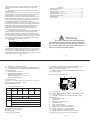
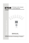
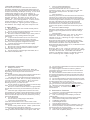
I. General Introduction
The brand new 510 Series instrument can measure
insulation resistance, AC voltage and phase sequence.
As a new generation all mighty electrical test instrument
we have successfully developed recently , it has made
fundamental changes to the circuit industry of
conventional insulation resistance . Aided by the nice
and fashionable design, 510 Series have more and
stronger functions , are easier to use and more
reliable . The instrument and accessories are all in
the toolbox , fit for field application . It can be used to
test the insulation resistance of power system ,
electrical equipment , lightning arrester equipment ,
and measure AC voltage and phase sequence test .
II. Safety Rules
1.
Be sure to read this user manual carefully before
using this instrument.
2.
Do not use this instrument when the rear cover is not
in place, or you may get electrical shock.
3.
Be sure to check the insulation layer of the probe is
sound and free of any damage before using this
instrument.
4.
To prevent electrical shock, be sure not to touch
electric lead and circuit when the test is in process.
5.
Be sure to confirm the range selection switch has
been set in the appropriate range before testing.
6.
Confirm the plug of the wire has been tightly
inserted in the terminal.
7.
Be sure not to use the instrument when it is moist
8.
Be sure not to turn the function selection switch
when the test is in process.
9.
Do not apply any voltage higher than 600V, AC or
DC between test terminals.
2
VI. Operation Instruction
1.
Safety Precautions
Be careful of the high voltage shock. When the
①
insulation resistance test is over, be sure to confirm the
high voltage on the object under test has been
discharged.
Do not touch the object under test when the test is in
②
process in case you should get electrical shock.
The object under test shall not be live and be sure to
③
confirm the object under test is securely earthed when
you test the insulation resistance . Short circuit the
two test terminals of the object under test to
discharge before you start the test .
Do not include any external voltage into the test loop
④
when you test the insulation resistance.
Be sure to confirm the knob switch is in right position
⑤
and the test wire is firmly connected before you start the
test.
When the high voltage switch has been turned on,
⑥
up to 5000V high voltage is generated between L terminal
and E terminal . Be sure not to touch any exposed part of
instrument and the object under test, otherwise you may
get electrical hazard.
2.
AC Voltage Test
Do not test any voltage higher than 600V.
①
Connection of Test Terminals.
②
Insert the red test lead into the ACV socket of the
instrument and the black test lead into the G socket of the
instrument.
Set the rotary switch at the “600V”position and
③
connect the probe to the object under test.
The value displayed by the instrument now is the AC
④
voltage between two terminals of the object under test .
6
3.
Test of Insulation Resistance.
Connection of Test Terminals
①
Insert the red test lead into the L socket of the
instrument and the plug of the black test lead with
flat crocodile clamp into the E socket of the
instrument .
Test connection
②
The wiring of E socket of the instrument is the earth wire ;
The wiring of L socket of the instrument is the line wire.
The G terminal socket of the instrument is the shield wire
to test the high insulation resistance. If necessary, insert
the plug of the black test wire with probe into the G
terminal socket of the instrument, to eliminate the
measurement error caused by the leak current in the
surface of the product, and ensure the accuracy of the
test ;
③
Selection of Rated Voltage
Select the rated voltage you need to test the insulation
resistance by turning the knob to the relevant voltage
class.
④
Test Operation
Connect the other terminal of the wire to the object
under test . Press the Test / Stop key , the red
indicator turns on , indicating the high voltage output
of test is connected.
When the test has started, the LCD of the instrument
displays some readings. The value displayed by LCD is
the insulation resistance of the object under test.
When the high voltage indicator is on, it indicates the test
instrument is working properly.
Turn off
⑤
When the test is over , press the Test / Stop key , the
red indicator turns off , indicating the test high voltage
has been disconnected . Put the DIP switch at OFF
position, LCD displays nothing. For capacitive load, be
sure to discharge the residual charges in the
7
10. Do not test in inflammable environment since spark
may lead to explosion.
11. Stop using the instrument in case any metal is
exposed because the shell or test wire is broken when
the test is in process.
12. Be sure that the test wire has been removed from
the test terminal and the function range selection switch
is in the OFF position when you remove the rear cover to
replace battery.
13. Do not replace battery when the instrument is moist.
14. Be sure to put the function range selection switch at
the OFF position when your work is over.
15. Remember to remove the battery when you are
going to not use the instrument for a long period of time.
16. When the instrument displays “
” , replace
battery promptly , to ensure the accuracy of
measurement .
III. Performance Features
1.
Low power consuming CMOS dual integral A/D
conversion IC, automatic zero
2.
LCD: 3 1/2 bit large screen display, maximum
reading 1999
3.
Data holding function, functional icons display
4.
Can measure voltage lower than AC600V
5.
Low Battery indication
6.
LCD backlight function
7.
Can test phase sequence
8.
Automatically convert range ( Insulation test only )
9.
Perfect protection circuits, which can effectively
prevent the harm of reverse voltage
10. LCD dimension: (65x48)mm (digit is 29 mm high )
11. Power: 8x1.5V (R6 AA) battery
3
object under test before you remove the test wire , to
prevent the residual charges discharge and harm
people .
4.
Phase Sequence Measurement Method(5101A,
5102A,5103A)
There is high voltage in the 3 - phase wire . It would be
highly dangerous to touch, therefore be sure to handle
with care when you connect wires for a 3-phase
measurement. In case the instrument indicator is not on
when the test wire has been connected, one phase may
be live. Be careful not to get shocked. Do not test any
voltage that is higher than the rated voltage of
100V450V / 40-60Hz ( 3- phase AC ) . Do not measure
for more than 30 minutes when the voltage is higher than
200V and not more than 3 minutes when the voltage is
higher than 450V. The duration mentioned above
commences from the moment the probe wires of two
phase sequences are connected.
The phase sequence function allows you to test the
①
phase sequence of 3-phase AC power supply (100V450V/40-60Hz). When you have connected the phase
sequence probes with the test wires by input terminals ,
you can judge the positive phase and reverse phase
of 3 - phase AC according to LED indicator and beep,
and phase missing indicated by LED .
Test State
②
Phase Sequence Test Indication
Open Phase Test Indication
Beep
Positive phase (CW indicator is on)
L1, L2 and L3 indicators are on.
Long beep
Reverse phase (CCW indicator is on) L1, L2 and L3 indicators are on.
No beep
Missing phase (CCW indicator is on)
No beep
Any of L1, L2 and L3 is not on
Note: When the measurement probes have been
connected, the phase sequence measurement function
shall indicate the positive phases and reverse phases of
a 3-phase AC, and the LED indicator will indicate the
phase missing. Be sure to measure with 3 triple-color test
wires with 3 round crocodile clamps .
Contents
General Introduction … … … … … … … … …………2
Safety Rules … … … … … … … … … … … … …………2
Performance Features … … … … … … … … …………3
Specification … … … … … … … … … … … … …………4
Operation Schematic View … … … … … … …………5
Operation Instruction… … … … … … … … … …………6
Maintenance … … … … … … … … … … … … …………9
Accessories … … … … … … … … … … … … …………9
Warning
This user manual includes warning
and safety specifications, which shall be
strictly followed to ensure safety. Please
be sure to read through this user manual
before using this instrument.
8
1
12. Dimension: 190x155x75mm
13. Weight: approximately 900g(including batteries)
14. The instrument and accessories can be put into one
for easy carriage
15. Environment conditions
16. Operating temperature: 0C~40C
Relative humidity<80%
Storage temperature: -10C ~50C
Relative humidity<80%
3.
Phase Sequence Test(only 5101A,5102A,5103A)
Phase-phase voltage range tested: 100V-450V
Frequency tested: 40-60Hz
4. Phase Sequence test result is indicated by LED No
and display in LCD
V. Operation Schematic View
1
2
3
INSULATION
HV
IV. Specification
Accuracy: ( %reading+digit ) the warranty is one year
Environment temperature: 23℃±5℃
Relative humidity: <75%
1.
Insulation Resistance
Model
Testing
Volatge
Out Voltage
Range
5103A
5101A
5102A
250 / 500
/ 1000V
500 / 10 0 0 10 00 / 250 0 250 / 500
100 / 250
/ 10 0 0 / 2500V / 5 0 0 / 1000V
/ 2500V
/ 5000V
5104A
90%-110% of the test voltage
0.1MΩ-20GΩ
0.1MΩ-200GΩ
0.1MΩ-20GΩ
0.01MΩ
Resolution
0.1MΩ-200MΩ±(3%rdg+5dgt)
Accuracy
5105A
200MΩ—10GΩ±(5%rdg+5dgt)
10GΩ—200GΩ±(10%rdg+5dgt)
2.
AC Voltage Measurement
Measurement range: 0-600V
Accuracy: ( 2% rdg+5dgt )
Resolution:1V
Test frequency: 50/60Hz
4
L1
L2
L3
D.H
PHASE
CW
CCW
13
12
11
L1
L2
E
L
10 9
L3 / G MAX
Test
4
5
6
7
700V
ACV
8
1.
LCD display
2.
Phase sequence measurement LED indicators (CW,
CCW, L1, L2 and L3)
3.
Insulation resistance measurement high voltage
LED indicator
4.
Data holding switch
5.
Test button
6.
Backlight indicator switch
7.
Function switch
8.
ACV Input terminal
9.
LINE input terminal ( Insulation )
10. EARTH input terminal ( Insulation )
11. Phase sequence L 1 input terminal
12. Phase sequence L2 input terminal
13. Phase sequence L3/ACV measurement G
terminal / shield input terminal for insulation
5
510 Series
Digital Insulation Resistance Tester
OPERATION MANUAL
Model:
5101A
5104A
5102A
5105A
5103A
Rev 4 . 0
510 Series
Digital Insulation Resistance Tester
OPERATION MANUAL
Model:
5101A
5104A
Rev 4 . 0
5102A
5105A
5103A
VII. Maintenance
This instrument is a precision electronic instrument, be
sure to maintain it well.
1.
Do not apply the instrument to any AC voltage
higher than 600V.
2.
Do not use the instrument when the rear cover of the
instrument is in place.
3.
To replace battery, remove the probe and power off
the instrument first. Unscrew the screws of the battery
cover and remove the battery cover. Be sure to replace
the battery according to the specification requirement.
4.
Do not forget to remove the battery if you are not
going to use the instrument for a long period of time .
Place the instrument at a dry and well ventilated
environment.
5.
Do not alter any internal circuit of this instrument at
will in case it is damaged.
VIII. Accessories
1.
One copy of user manual
2.
1 toolbox
3.
2 sets of dedicated test wires (a phase sequence
test wire, an insulation resistance test wire
4.
8 cells of 1.5V AA batteries
9