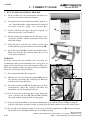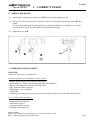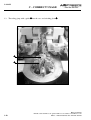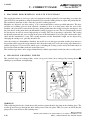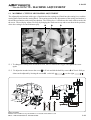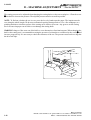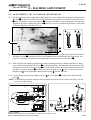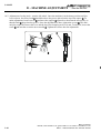
1
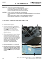
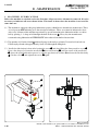
MODEL
S-104.M
EYELET BUTTONHOLE MACHINE
PARTS AND SERVICE MANUAL
MACHINE SERIAL No.
PART NUMBER
97. 1410.0.000
This manual is valid from the serial No.: L142913M
AMF is trademark of AMF Group, Inc.
09/2012
LIMITED WARRANTY ON NEW AMF REECE EQUIPMENT
Warranty provisions:
A ninety (90) day limited service labor warranty to correct defects in installation, workmanship, or material without charge for
labor. This portion of the warranty applies to machines sold as ”installed” only.
A one (1) year limited material warranty on major component parts to replace materials with defects. Any new part believed
defective must be returned freight prepaid to AMF Reece, Inc. for inspection. If, upon inspection, the part or material is determined to be defective, AMF Reece, Inc. will replace it without charge to the customer for parts or material.
Service labor warranty period shall begin on the completed installation date. Material warranty shall begin on the date the
equipment is shipped from AMF Reece, Inc.
Exclusions:
Excluded from both service labor warranty and material warranty are: (1) Consumable parts which would be normally considered
replaceable in day-to-day operations. These include parts such as needles, knives, loopers and spreaders. (2) Normal adjustment
and routine maintenance. This is the sole responsibility of the customer. (3) Cleaning and lubrication of equipment. (4) Parts
found to be altered, broken or damaged due to neglect or improper installation or application. (5) Damage caused by the use of
non-Genuine AMF Reece parts. (6) Shipping or delivery charges.
There is no service labor warranty for machines sold as ”uninstalled”.
Equipment installed without the assistance of a certified technician (either an AMF Reece Employee, a Certified Contractor, or
that of an Authorized Distributor) will have the limited material warranty only. Only the defective material will be covered. Any
charges associated with the use of an AMF Reece Technician or that of a Distributor to replace the defective part will be the
customer’s responsibility.
NO OTHER WARRANTY, EXPRESS OR IMPLIED, AS TO DESCRIPTION, QUALITY, MERCHANTABILITY, and FITNESS FOR
A PARTICULAR PURPOSE, OR ANY OTHER MATTER IS GIVEN BY SELLER OR SELLER’S AGENT IN CONNECTION HEREWITH. UNDER NO CIRCUMSTANCES SHALL SELLER OR SELLER’S AGENT BE LIABLE FOR LOSS OF PROFITS OR ANY
OTHER DIRECT OR INDIRECT COSTS, EXPENSES, LOSSES OR DAMAGES ARISING OUT OF DEFECTS IN OR FAILURE OF
THE EQUIPMENT OR ANY PART THEREOF.
WHAT TO DO IF THERE IS A QUESTION REGARDING WARRANTY
If a machine is purchased through an authorized AMF Reece, Inc. distributor, warranty questions should be first directed to that
distributor. However, the satisfaction and goodwill of our customers are of primary concern to AMF Reece, Inc. In the event that
a warranty matter is not handled to your satisfaction, please contact the appropriate AMF Reece office:
Prostejov,
Phone:
Fax:
e-mail:
Czech Republic
(+420) 582-309-286
(+420) 582-360-608
[email protected]
Warranty Registration Card
(Please Fax or Mail immediately after installation)
Note: All Warranty Claims Void, unless Registration Card on file at AMF Reece HQ
Machine model number:
(S100, S101, S104, S105, S 311, Deco, S4000 , EBS Mark II, ES505, etc)
Manufacturer‘s serial or production number:
Installation Site Information:
Customer‘s Name:
Customer‘s Mailing Address:
Customer‘s Telephone Number:
Supervising Mechanic‘s or Technician‘s Name:
Signature of Supervising Technician:
AMF Reece Technician‘s Name:
AMF Reece Technician‘s Signature:
Type of garment produced at this location?
Average Daily Production Expected from this machine?
(number of buttonholes, jackets sewn, pants produced, buttons sewn, etc)
Any special requirements required at this location?
What other AMF Reece Machines are at this location?
How can we serve you better?
Tovární 837, 798 11 Prostejov, Czech Republic
Fax: +420 582 360 606, e-mail: [email protected], website: www.amfreece.com
S-104.M
TABLE OF CONTENTS
A - INTRODUCTION
1.
2.
3.
4.
5.
6.
7.
8.
General information .......................................................................................................................... 1-1
Safety labels and decives .................................................................................................................. 1-2
Terminology of machine parts ........................................................................................................... 1-3
Terminology of butttonhole parts ...................................................................................................... 1-4
Technical condition ........................................................................................................................... 1-5
Coloured markings ............................................................................................................................ 1-6
Safety instructions for operators and servicemen ............................................................................... 1-6
Special equipment ............................................................................................................................. 1-8
B - MACHINE INSTALATION
1.
2.
3.
4.
5.
Contents of consigment ..................................................................................................................... 1-9
Sewing head instalation onto the table ............................................................................................... 1-9
Thread stand instalation ................................................................................................................... 1-10
Connecting machine with distribution of electricity .......................................................................... 1-11
Belt tension assembly and adjustment ............................................................................................. 1-15
C - CORRECT USAGE
1. Buttonhole sewing process ............................................................................................................. 1-16
2. Needle exchange ............................................................................................................................ 1-17
3. Threading the machine .................................................................................................................... 1-17
4. Principles of sewing ........................................................................................................................ 1-21
5. Machine description and its functions .............................................................................................. 1-22
6. Changing seaming width ................................................................................................................. 1-22
7. Stitch density adjustment / changing the buttonhole shape - with - withot eye ................................. 1-23
8. Stitching lenght and flybar adjustment ............................................................................................ 1-24
9. Changing the position of stitch row - gaps for cut ........................................................................... 1-25
10. Setting the spread of the clamp feet ................................................................................................. 1-25
D - MACHINE ADJUSTMENT
1. Table adjustment ............................................................................................................................. 1-26
2. Stopping mechanism ....................................................................................................................... 1-28
3. Stopping stroke adjustment ............................................................................................................. 1-30
4. Barke adjustment ............................................................................................................................ 1-31
5. Turning mechanism alignment ......................................................................................................... 1-32
6. Buttonhole shape adjustment .......................................................................................................... 1-33
7. Needle bar height ............................................................................................................................ 1-34
8. Loopers adjustment ......................................................................................................................... 1-35
9. Spreaders adjustment ...................................................................................................................... 1-37
10. Upper thread trimming .................................................................................................................... 1-38
11. Upper thread tension ....................................................................................................................... 1-39
12. Sewing switch lewer ....................................................................................................................... 1-40
13. Material cutting mechanism adjustment ........................................................................................... 1-41
14. Adjustment of clamping mechanism ............................................................................................... 1-43
15. Cut before and cut after adjustment ................................................................................................ 1-45
E - MAINTENANCE
1.
2.
3.
4.
Machine cleaning and maintenance ................................................................................................. 1-46
Summary of maintenance ................................................................................................................ 1-47
Machine lubrication ......................................................................................................................... 1-48
Disposal provisions .......................................................................................................................... 1-51
Released 03/2010
E-mail: [email protected]; [email protected]; website: www.amfreece.com
Phone: +420 582 309 286; Fax: +420 582 360 606
0-1
S-104.M
TABLE OF CONTENTS
0-2
Released 03/2010
E-mail: [email protected]; [email protected]; website: www.amfreece.com
Phone: +420 582 309 286; Fax: +420 582 360 606
S-104.M
A - INTRODUCTION
1 . G E N E R A L I N F O R M AT I O N
S-14.M sewing machine is intended for sewing buttonholes on outwear. It has been designed and
manufactured to be reliable and easy to operate. Special attention is paid to ensure ease and effective
safety for machine operators and servicemen.
Safety mechanisms protect both, operators and the machine, and respect valid safety and hygiene provisions
for usual technological usage of the machine. Those safety mechanisms contain electrical plug, operation
switch (circuit breaker) and covers ensuring safety operation on the machines; only if they are fitted onto
the machine correctly.
There are information labels on the machine to point out additional danger. Do not remove or damage
those labels. In case of damage, order a new one. Mentioned warnings cannot cover all safety aspects and
therefore it is very important for an operator to read this manual carefully and understand it well before he
starts operating the machine. It will also eliminate errors during machine installation and its operation. Do
not put the machine into operation unless you have read entire manuals supplied with the machine and
have understood each function and procedure.
There are four categories of safety instructions in this manual:
DANGER!
Ignoring instructions may endanger operator’s life.
CAUTION!
Ignoring instructions may cause a serious injury of the operator or damage the machine.
WARNING!
Ignoring instructions may cause damage on the machine or injury of the operator.
NOTICE!
Breaking procedures may cause functional problems of the machine.
We recommend that servicemen from AMF Reece supervise the installation of the machines and initial
training of your mechanics and operators.
The most effective method ensuring safety of operators working on the machine is a strict safety program
including instructions for safety operation. Operators and servicemen should wear safety glasses.
Released 03/2010
E-mail: [email protected]; [email protected]; website: www.amfreece.com
Phone: +420 582 309 286; Fax: +420 582 360 606
1-1
S-104.M
A - INTRODUCTION
2. SAFETY LABELS AND DEVICES
Ê
Ë
Ì
Í
Caution when removing cover,
electric current possible injury
Danger - possible injury
Caution when removing cover, possible injury
Grounding
Ë
Ê
Ì
Î
Ï
Ð
Ñ
Ò
Rotation direction
Switch
Needle guard
Drive belt cover
Foot pedal
Í
Î
Ñ
Ð
Ï
Ò
1-2
Released 03/2010
E-mail: [email protected]; [email protected]; website: www.amfreece.com
Phone: +420 582 309 286; Fax: +420 582 360 606
S-104.M
A - INTRODUCTION
3. TERMINOLOGY OF MACHINE PARTS
Ó
Thread stand
Table
Stand
Hand wheel
Drive belt cover
Motor
Hand screw
Needle bar
Clamp feet
Stop lever
Start lever
Cutting lever
Sewing table
Ó
Released 03/2010
E-mail: [email protected]; [email protected]; website: www.amfreece.com
Phone: +420 582 309 286; Fax: +420 582 360 606
1-3
S-104.M
A - INTRODUCTION
4 . T E R M I N O L O G Y O F B U T T O N H O L E PA R T S
12
3
13
2
8
1
5
10 mm
9
6
11
10
4
Ê First row of stitches
7
Ñ Length of cut. Material can be cut before
Ë Second row of stitches (CA)
sewing (CB) or after sewing (CA) the
Ì Density in the eye
buttonhole. Cut before (CB) can be used on
Í Shear gap
firm thick materials only
Î Stitch density = the number of stitches in 1 cm Ò Total buttonhole length = lenght of sewing
(C7)
mehsuped from the top of cutting
The bigger density, the better quality look of
the buttonhole
Ó Flybar (AF)
Open end
Ï Bite size = the width of side stitches (C6)
Eye width (material cutting)
Eye length (material cutting)
Ð Lengthwise pre-sewing
1-4
Released 03/2010
E-mail: [email protected]; [email protected]; website: www.amfreece.com
Phone: +420 582 309 286; Fax: +420 582 360 606
S-104.M
A - INTRODUCTION
5. T E C H N I C A L C O N D I T I O N S
S-104.M Mechanical eyelet buttonhole machine with chain stitch can be used on men and ladies’ garments.
Gimp can be also used. With a simple change, the following types of buttonholes can be sewn:
- flybar
- with eye
- without eye
Description
- without bar
- with eye
- without eye
Parameters
Sewing speed
Stitch type
Buttonhole
lenght
Up to 1900 spm
401 two thread chainstitch
Stitch density
3 - 16 st/cm
4 to 12
2 ...4 mm
Stitch bite
Buttonhole types
Eye types
Fly bar lenght
Maximum clamp height
Maximum work thickness
Buttonhole cutting mode
Cutting space
Bedplate movement
Needle system
Recomended thread*
Operating condition
Machine db level
Machine head dimension
Machine head weight
Table dimension
Machine weight
Electrical requirements
13 - 32 mm (1/2”-1 1/4”)
No eye; 2,7x 4,3 mm
3,0 to 7,0 mm
10 mm
to 6 mm
Cut before (CB),
Cut after (CA)
- 0,50 to + 1,8 mm
40 mm
02.0501.0.111 (Nm 90, 100, 110)
70, 100, 120,
gimp 11{120.
Yes
According to IEC 364-3, IEC 364-5-51 temperature from +5°C to 40°C, relative air humidity from 30 to 8 0%
Max. 80 dB/ stoping 82 dB
800 mm (height)
x 640 mm (width)
x 790 mm (depth)
89 kg (152 lbs)
750 mm (height)
x 1100 mm (width)
x 700 mm (depth)
230 V
400 V
230 V
110 V
158 kg
50/60 Hz
50/60 Hz
50/60 Hz
60 Hz
3 Ph
3 Ph
1 Ph
1 Ph
NOTICE!
If you use threads 100 thick or less, the manufacturer recommend using the left looper order number
11.4005.0.005
Released 03/2010
E-mail: [email protected]; [email protected]; website: www.amfreece.com
Phone: +420 582 309 286; Fax: +420 582 360 606
1-5
S-104.M
A - INTRODUCTION
6. C O L O U R E D M A R K I N G
Screw - top links:
Yellow marks — 1. Loosing and following disassembly of this link causes
distinctive intervention to the mechanism adjustment, was
done when assembled and sewed off at the that factory.
2. After such an intervention to the mechanism, new
adjustment of set mechanism needs to be done and complete
check of whole machine adjustment as well.
Lubrication locations:
Blue marks
— Screws and nuts secured against loosing with glue
„LOCTITE“.
Red marks
— CAUTION: Lubrication regime adherance is necessary
for protection of the reliable long-term machine operation.
7. S A F E TY I N S T R U C T I O N S F O R O P E R AT O R S A N D S E R V I C E M E N
When positioning the machine onto its operational place, we recommend keeping the minimal distance of
the machine as in the drawing. Follow the instructions below. Do not start the machine unless you have
carefully read the operator’s manual.
1-6
Released 03/2010
E-mail: [email protected]; [email protected]; website: www.amfreece.com
Phone: +420 582 309 286; Fax: +420 582 360 606
S-104.M
A - INTRODUCTION
DANGER!
- Before connecting the machine with the power, make sure all covers are mantled onto the machine.
- If any of the safety covers needs to be dismantled, turn the main switch off, and possibly unplug the
power from the socket.
- Do not connect the machine with the power if any of the covers is dismantled.
- Once the machine is connected with the power, check the rotation of the pulley.
CAUTION!
- Remember the position of the switch so that you can use it from any position.
- Make sure that the power, its dimension and circuit breaker provides constant power supply to ensure
reliable performance of the machine.
- Check that none of the cables is damaged in order to prevent accident injury from happening by touching
them.
- Damaged covers must be immediately repaired or replaced with new ones.
- Never touch rotating parts.
- Never put fingers into the sewing area.
- Turn the main switch off before you change a needle.
- Unplug the power cord from the socket before you clean or maintain the machine.
- If you do not work on the machine, disconnect the power with the main switch.
- Do not make any modifications in the machine that would endanger its safety.
- Be aware that every machine part can become dangerous if they are not handled or serviced the right
way. It is important that everybody working with the machine – operate it or do the maintenance on it –
gets acquainted with information in this instruction book and in the spare parts manual.
WARNING!
- Keep maintaining the machine regularly as described in the manual.
- If the power is cut off, turn the main switch off.
- Do not paint, do not damage, do not remove or change the safety labels. Keep them clean. If they are
not legible or you loose them, order new ones at our company and place it onto their original location.
- Bind your long hair – it can be caught and winded by the driving mechanism.
- Buttons (hooks) on your sleeves must be buttoned up so that loose parts of your outfit are not winded
into the driving mechanism.
- Do not work onto the machine impaired or intoxicated.
- If you are unsure of the operation process, call up a serviceman.
- The machine user must provide for illuminating the working area – minimum 750 Lux.
Released 03/2010
E-mail: [email protected]; [email protected]; website: www.amfreece.com
Phone: +420 582 309 286; Fax: +420 582 360 606
1-7
S-104.M
A - INTRODUCTION
8. S P E C I A L E Q U I P M E N T
8.1. Work light Ê
- standard light can be ordered additionally, order number
12.0008.4.875
8.2. Set up gauge Ë
- 03.0279.1.000
Ê
8.3. Buttonhole distance kit Ì
- 03.5511.0.003
8.4. Loopers
-11.4005.0.001 - for single thread stitch
-11.5005.0.005 - for sewing thin threads
Ë
Ì
1-8
Released 03/2010
E-mail: [email protected]; [email protected]; website: www.amfreece.com
Phone: +420 582 309 286; Fax: +420 582 360 606
S-104.M
B - MACHINE INSTALLATION
1. CONTENT OF CONSIGNMENT
1.1. If not stated otherwise, the consignment contains the following:
Ê
- machine head
- cardboard with accessories
(specification in the Spare Parts section 3-58)
- thread stand dismantled Ê
- operator’s manual with Spare Parts list
- stand dismantled with motor (if ordered)
1.2. When unpacking the machine, it is necessary to follow marks
placed on the wrapping.
WARNING!
Visible damaged of the consignment that happened during the shipment must be immediately reported to
the carrier. Check the content of the consignment with the order. Possible impediments must be immediately
reported to the manufacturer. Later claims cannot be acknowledged!
2 . SEWING HEAD INSTALATION ONTO THE TABLE
WARNING!
Do not lift the sewing machine by the table
but by iron the machine.
NOTE!
If not supplied with the
machine a full instruction
manual for assambling the
manufacturer, order
number 97.0104.0.020.
780
2.1. Once you unpack the machine, install it onto its intended place. Follow the instructions in this
service manual page 3-56 to asamble the stand dismantled. The machine is supplited with a stand
of a standard height. The recommended height of the table is 780 mm measured from the floor.
For work while seated use a chair with adjustable height. The desk height can be adjusted by
lifting it up once loose the screws Î . Tighten the screws firmly after the adjustment.
2.2. The stability is secured with the rear
support Ë, that is operated with a
hand screw Ì. Check the desk level.
2.3. Place the pubber cushions Í ,
supplied in the standard accessory,
onto, appropriate holes of the table.
2.4. Unpack the sewing head Ï, set it
onto the rubber cushions Í. To
fasten the sewing head liseing the
screws Ð, the steel washers Ñ and
the rubber cushions Ò, supplied in
the standard accessory.
Ë
Released 03/2010
E-mail: [email protected]; [email protected]; website: www.amfreece.com
Phone: +420 582 309 286; Fax: +420 582 360 606
1-9
S-104.M
B - MACHINE INSTALLATION
3 . T H R E A D S TA N D I N S TA L L AT I O N
3.1. Put the thread stad together according
to the drawing
3.2. Position of the locking ring Ê allows
assembly of the thread stand for various
thicknes of table top. Threaded end of
the post Ï must not extend more
than 1 mm (1/32“) through the locking
nut Î
3.3. Insert the washer Ë and the post into
the hole provided in the right rear of
the table top Ì. Insert the washer Í
and tighten the nut Î.
1-10
Released 03/2010
E-mail: [email protected]; [email protected]; website: www.amfreece.com
Phone: +420 582 309 286; Fax: +420 582 360 606
S-104.M
B - MACHINE INSTALLATION
4 . C O N N E C T I N G M A C H I N E W I T H D I S T R I B U T I O N O F E L E C T R I C I TY
4.1. Once you mount the machine sewing head onto the stand connect the power cord with the socket.
No appliances can not be connected with the socket - circuit protection. Teh pulley in teh rear left
must rotate clock wise once you connect the power cord with the socket, switch on the switch
and press the foot pedal.
CAUTION!
It is necessary to connect the conductive construction elements of the machine according to the diagram
number 4.7.
WARNING!
The electrical connection can be done by an appropriate electrical qualification person only. power point.
The pulley placed under the rear removable cover must turn clockwise when connected to the power
point, when the switch turned on and when the foot pedal pressed down.
4.2. Diagram connection legend:
XP
QMF1
M1
W1
W2
C1
- main switch - plug
- workswitch - circuit breaker
- motor
- feed cable
- feed cable for M1
- starting capacitor
4.3. Diagram of connection 1N+PE 110V/60Hz:
17.0007.8.171
Released 03/2010
E-mail: [email protected]; [email protected]; website: www.amfreece.com
Phone: +420 582 309 286; Fax: +420 582 360 606
1-11
S-104.M
B - MACHINE INSTALLATION
4.4. Diagram of connection IN+PE 230V/50Hz
17.0007.8.172
4.5. Diagram of connection 3N+PE 230V/60Hz:
17.0007.8.173
1-12
Released 03/2010
E-mail: [email protected]; [email protected]; website: www.amfreece.com
Phone: +420 582 309 286; Fax: +420 582 360 606
S-104.M
B - MACHINE INSTALLATION
4.6. Diagram of connection 3N+PE 400V/50Hz
17.0007.8.173
4.7. Diagram of connection of conductive construction elements
Outer connector for potential difference
equalizing marked in the scheme.
Released 03/2010
E-mail: [email protected]; [email protected]; website: www.amfreece.com
Phone: +420 582 309 286; Fax: +420 582 360 606
1-13
S-104.M
B - MACHINE INSTALLATION
4.8. Instalation diagram
- EYLET BUTTONHOLE MACHINE
- WORK SWITCH-CIRCUIT BREAKER WITH OVERCURRENT PROTECTION SM 1-2,5
- MAIN SWITCH, PLUG
- 3 F MOTOR; 1148
- FEED CABEL
- FEED CABEL FOR M1
- OUTER CONNECTOR FOR POTENTIAL DIFFERENCE EQUALIZING SCREW M6-30 FROM BRASS
- INSRTION TRAY
- CLIP “A”
PROTECTION FROM DANGEROUS TOUCH REALIZED ACCORDING TO EN 60204-1
1-14
Released 03/2010
E-mail: [email protected]; [email protected]; website: www.amfreece.com
Phone: +420 582 309 286; Fax: +420 582 360 606
S-104.M
B - MACHINE INSTALLATION
5. BELT TENSION ASSEMBLY AND ADJUSTMENT
CAUTION!
According to electrical power freqvency is necessary to use the motor pulley Î 50Hz or 60 Hz. (If the motor
rotations are higher then is reccommend by the manufacturer, the machine can get damaged)
1. Remove the belt cover Ê and the frame Ë. Put V-belt Ì on the pulley Í and over the hole in table on
motor pulley Î .
2. Loose the nut Ï and turn the motor Ð tighten the belt and tighten back the nut.
3. Check the tightein with 30 N pressure. Belt sag should be around 20 mm.
4. Check the pulley rotation direction to make sure the pulley rotates counter clock wire.
5. Install belt cover Ê and the frame Ë.
mm
20
N
30
Motor — 50Hz, 1400 RPM
60Hz
42,3 mm
53 mm
50Hz
(EU)
60Hz
(USA)
Released 03/2010
E-mail: [email protected]; [email protected]; website: www.amfreece.com
Phone: +420 582 309 286; Fax: +420 582 360 606
1-15
S-104.M
C - CORRECT USAGE
1 . B U T T O N H O L E SEWING PROCESS
1.1. Read carefully all safety instructions and make sure
all covers are mantled onto the machine.
1.2. Put lubrication oil into lubrication holes marked as
„oil“, check that theke a right amount of oil in the oil
reservoir with oil gauge (see section E3).
Ê
1.3. Check, whether the upper thread and gimp are
threaded correctly, as in Section C3.
1.4. Before starting the machine for the first time, put a
small piece of fabric, similar to your piece to be sewn,
under the clamps.
1.5. Plug the power cord into the socket and start the
motor with the operation switch (circuit breaker) Ê.
1.6. Press the foot pedal Ë to activate the machine drive.
Make sure that the drive pulley under the rear tilt
cover moves clockwise.
WARNING!
To make certain that the machine sews correctly, we
recommend sewing a few buttonholes on a scrap piece of
fabric. It will also remove excess oil from the sewing area.
When the machine is in the operation, do not try to hold or
move the sewn fabric with your hands.
Ë
Ì
Ñ
1.7. Place the fabric under the clamp feet.
Í Ï
1.8. Moving the lever for manual clamping Ì towards
the operator will bring the clamping feet Ñ down
and they will clamp the fabric.
1.9. Press the start up lever Í. The clamping feet go down
automatically. Once the sewing is finished and
buttonhole cut, the clamping feet go up.
Ð
1.10. If it is necessary to interrupt the sewing during the
cycle, pull the stop lever Ï. The machine finishes
the cycle without sewing and the clamps go up.
1.11. You can stop the machine at any moment during the cycle with the foot pedal Ë (pressing the
pedal by your tiptoe stops the sewing, pressing the pedal with your heel starts the sewing again).
1.12. To start the cycle witmout sewing, it is necessary to lift the supporting lever Ð and once youturn
the machieon, the machine finishes the cycle without sewing.
1-16
Released 03/2010
E-mail: [email protected]; [email protected]; website: www.amfreece.com
Phone: +420 582 309 286; Fax: +420 582 360 606
S-104.M
C - CORRECT USAGE
2 . NEEDLE EXCHANGE
2.1. Loosen the securing screw of the needle Ë and remove the original needle.
2.2. Place the needle so that the grove A of the needle is on the other side than the tensor Ì. The
needle
must not have broken tip or other defect. You can check whether it is straight, if you roll the
needle on the flat pad. A good needle does not deflect in the tip.
2.3. Tighten the screw Ë.
Ë
3 . THREADING THE MACHINE
WARNING!
make sure the power is switched off!
Look and quality of the buttonhole is influenced by:
- threads, their elasticity and resistance to breakage
- thread thickness – make sure that thread has the same thickness
- material sewn (thickness, density, fiber direction)
- upper and lower thread tension
- stitch density - see section A5
- stitch width
- technology of sewing process (size of material spreading, distance of stitches from the cut edge)
Correct buttonhole should have:
- uniform stitch density
- consistent chain formation
- symmetric eye shape
- proportional shape and size
- smoothly trimmed threads
Released 03/2010
E-mail: [email protected]; [email protected]; website: www.amfreece.com
Phone: +420 582 309 286; Fax: +420 582 360 606
1-17
S-104.M
C - CORRECT USAGE
Pull threads on as shown in the pictures below. Use the threading tool Ê (in the machine accessories) to
make the pulling easier. The threading tool Ë can be ordered (order number 12.0008.6.200). Thread
tension is adjusted with the nut Í as per sewing conditions. It is necessaryto side adjust the thread passes
position, that passes through the fixedthread tension Ì considering the upper adjustable thread tension
dises.
3.1. Threading upper thread in the machine
Í
3.1
Ï.
3.2
Ð
THREAD
3.3
Í
Into needle bar
Ê
Form thread
supply
Ë
Ì
Í
Ì
Note: Thread makes 1,5x turns around the roller.
1-18
Released 03/2010
E-mail: [email protected]; [email protected]; website: www.amfreece.com
Phone: +420 582 309 286; Fax: +420 582 360 606
S-104.M
C - CORRECT USAGE
3.2. Threading lower thread
can be done once the machine arm lifted Ï . Is lifted and the clamping plates Ð are removed as shown in
the previous picture, process described in section E1, point 1.2.
Released 03/2010
E-mail: [email protected]; [email protected]; website: www.amfreece.com
Phone: +420 582 309 286; Fax: +420 582 360 606
1-19
S-104.M
C - CORRECT USAGE
3.3. Threading gimp with a guide Ñ into the race and stitching plate Ò .
Ò
Ñ
1-20
Released 03/2010
E-mail: [email protected]; [email protected]; website: www.amfreece.com
Phone: +420 582 309 286; Fax: +420 582 360 606
S-104.M
C - CORRECT USAGE
4. PRINCIPLES OF SEWING
S-105 machine manufactured by AMF Reece sews with a two-thread chain buttonhole stitch with the
possibility to use gimp Ì . The principle of a chain stitch is weaving two so called endless threads, upper
thread Ê and lower thread Ë , that enables sewing applications without the necessity to refill the supply of
lower thread – as it is usual when sewing lockstitches.
Ê
Ë
Ì
On a regular basis, gimp is inserted into the face side of the work piece (on the seam side – bottom side of the work piece when sewing onto the machine). The machine can be additionaly equipped with top
guide of gimp for its insection ON the seam side-bottom side of the work piece.
Gimp - creates plastic look of a buttonhole and together with a bottom thread
decorative stitch provides the shape and firmness of a buttonhole.
Decorative stitch – creates plastic shape nearer the cut. The upper thread
makes a covering stitching on the upper side of the fabric.
Released 03/2010
E-mail: [email protected]; [email protected]; website: www.amfreece.com
Phone: +420 582 309 286; Fax: +420 582 360 606
1-21
S-104.M
C - CORRECT USAGE
5 . M AC H I N E D E S C R I P T I O N A N D I T S F U N C T I O N S
The supplied machine is a box-type piece of equipment with an optimally raised working area above the
table desk. The arm with the sewing mechanism is placed in the folding frame to adjust and pull in threads.
The machine is installed so that t suits the seated or standing operator.
Machines are adjusted “cut after sewing” (CA) at the manufacturer, unless specified otherwise. The base
position of a working plate of such adjusted a machine is in its rear dead point. After the start of the
machine, the plate moves towards the operator, during which time the clamps clamp the work piece and
the plate moves to the point where the buttonhole sewing is suppose to start. The feet automatically stretch
the work piece in order to ensure high quality of sewing. The size of opening is adjustable. The sewing
mechanism automatically starts sewing in the place of the buttonhole by releasing the clutch of the drive
shaft and the buttonhole is sewn. The starting moment and the buttonhole length can be adjusted by
changing the cutting steel, possibly the knife too.
Once the sewing of a buttonhole is finished, the needle is set in the upper position and the plate moves to
the position where upper thread is trimmed. After that, the work piece is cut, the clamps open themselves
and the work piece is released. The whole cycle, excluding the sewing, can be run by the hand wheel on
the left side of the machine under the removable cover.
The machine operation can be stopped immediately with the operational switch (breaker) or table pedal.
6. CHANGING SEAMING WIDTH
The standard range of seaming width – from 2,0 up to 4,0 mm can be changed by loosing the nut Ê ,
shifting it up and down and tightening.
Ë
Ê
WARNING!
When adjusting this device, check the needle position against the hole for gimp in the stitching plate. The
needle tip must not go through the hole during centre and side prick. This way you can check that the
gimp will be sewn between the stitching rows.
1-22
Released 03/2010
E-mail: [email protected]; [email protected]; website: www.amfreece.com
Phone: +420 582 309 286; Fax: +420 582 360 606
S-104.M
C - CORRECT USAGE
7 . S T I T C H D E N S I TY A D J U S T M E N T / CHANGING THE BUTTONHOLE SHAPE WITH - WITHOUT EYE
Stitch density adjustment can be done throught the hole in the right side base cover.
7.1. To adjust the number of stitches, loose the nut Ê and move the drawbar Ë forward → A or
backward → B (forward to increase the number of stitches, backward to decrease the number of
stitches) as needed. Once you finish the adjustment, tighten the nut Ê .
7.2. The technique to change the number of stitches in the eye is different for sewing buttonholes with
eyes. The adjustments of a buttonhole whout eye (NO EYE) can be done once you remove the
back arm cover . To sew a buttonhole without eye, move the lever Ì forward → C. Loosen the
screw Í , move the pin Î forward or backward (forward to increase the number of stitches,
backward to decrease the number of stitches). Once you finish the adjustment, tighten the screw
Í . The pin Î controls the descent of the roll Ï on the inclined plane in the moment of the race
turning.
7.3. The change when sewing a buttonhole without/ with eyeis done by rotation of lever Ð about 180°
in the direction to the second position. Shown positionis sewing the buttonhole with eye (on the
lever is written „EYE“). The second position is for sewing the buttonhole without eye (on the lever
is written „NO EYE“).
Í
Ï
Ì
Ð
Î
Ê
Ë
NOTE!
The stitch density slightly changes as the main cam brake wears out during the machine operation.
Released 03/2010
E-mail: [email protected]; [email protected]; website: www.amfreece.com
Phone: +420 582 309 286; Fax: +420 582 360 606
1-23
S-104.M
C - CORRECT USAGE
8 . S T I T C H I N G L E N G T H A N D F LY B A R A D J U S T M E N T
8.1. The length of stitching, it means the moment when the sewing process begins with the movement of
working desk can be influenced as follows: loosen the screw Í of the dial gauge Î and move it Î so
that the required length of stitching on the dial gauge Î is at the same point as the edge of the mark Ë .
Tighten the screw Í . The total length of stitching L is now set up – see the picture.
WARNING!
The total length of stitching is the length of cut + the length of seaming.
8.2. If a buttonhole with flybar is to be sewn, it is necessary to loosen the screw Ê of the ruler Ì , move the
ruler Ì towards the operator (to obtain longer flybar) or off the operator (to shorten flybar, or eliminate
it). This is the technique to adjust the P length – see the picture.
L
L
P
WARNING!
If you adjust the length, you must install a cutting steel of the corresponding length.
D
C
Ì
Í
Ê
Î
Ë
1-24
Released 03/2010
E-mail: [email protected]; [email protected]; website: www.amfreece.com
Phone: +420 582 309 286; Fax: +420 582 360 606
S-104.M
C - CORRECT USAGE
9 . C H A N G I N G T H E P O S I T I O N O F S T I T C H ROW – G A P S F O R C U T
The change of the position of stitch rows is used especially when the thickness of the sewn material
changes or when the machine is adjusted from cut before to cut after and vise versa.
Loose the screw Ê and move it to change the setting as per the drawing it down the space for cutting
becomes larger by moveing it up the space for cutting becomes smaller.
Ê
WARNING!
When you change the gap between both rows of stitches, you may need to adjust the sewing mechanism
as well. It is also necessary to check, if the needle is not hitting the edge of the stitching plate so that the
needle will not brake.
10. SETTING THE SPREAD OF THE CLAMP FEET
Different types of material require larger or smaller spread of the material between the clamp feet. In order
to change the spread, use the setting shown in the picture.
Loosen the screw Ê at each side of the machine and move the setting stops Ë inward →A, to make the
spread wider - and outward →B, to make the spread narrower.
NOTE!
Make sure that the spread is equal on both sides.
Ë
Ê
Released 03/2010
E-mail: [email protected]; [email protected]; website: www.amfreece.com
Phone: +420 582 309 286; Fax: +420 582 360 606
1-25
S-104.M
D - MACHINE ADJUSTMENT
WARNING!
Do not start any maintenance work before you read the service manual
with instructions for mechanics – Sections D and E.
DANGER!
• before you start doing any maintenance work, always turn the operational switch (breaker) off and
unplug the power cord. That will eliminate the possibility of the machine being accidentally switched on
by another person.
• Make sure that the power cord is secured against any mechanical breakage.
CAUTION!
• Maintenance work must be done by a qualified person only.
• When changing defective parts, use parts corresponding with original ones.
• Do not run the machine unless all covers dismantled for maintenance purposes were placed back.
• Wipe away spilt oil. Keep the working area clean.
WARNING!
• Read carefully the entire manual for servicemen.
• Use specified kinds of lubrication or their equivalents only.
We are not responsible for claims that happen due to violating these instructions.
1 . TA B L E A D J U S T M E N T
NOTE!
The holder of switching pins of the fly bar is adjusted and fixed with pins at the manufacturer. There is no
need to adjust the pins if they move freely. In case the pins don´t snap in freely, follow below steps:
1.1. Adjust the machine for a buttonhole without eye according to the section C 7.3.
1.2. Lift up the machine. Turn the left shift Ê until the looper mechanism start turning. The roll Ë is in
the position Ò . Of the cam travel Ì . The switching pins Í must freely snap into the groov Ï .
1.3. At the end of the buttonhole, before the home position, in the beginning of the race return turn, the
right pin Í is in the guiding travel Î. Loosen the screew Ð on the lever . Adjust the lever Ñ, so
that the pin leaves the guiding travel freely without the table moving side ways. Tighten the
screwÐ .
1.4. After the machine is started again, by turning the hand wheel Ê and the race turning in the eye
(loopers in the rear position) adjust the of the right pin about half way 3 ...3,5 mm into the guuding
travel, by nuts on the draw bar .
1.5. Once the left pin snaps into the guiding travel (the narrower section of the travel), adjust the depth
of the pin about half way 3 ... 3,5 mm into the guiding travel Î as well, by nuts on the draw bar.
1-26
Released 03/2010
E-mail: [email protected]; [email protected]; website: www.amfreece.com
Phone: +420 582 309 286; Fax: +420 582 360 606
S-104.M
D - MACHINE ADJUSTMENT
1.6. Once the roll Ë is moved into the furthest position from the at the bottom of the eccentric (looking
from the right side) before the eye (before turning the race) adjust the position so that the left pin is
about 1 mm above the guiding travel.
Ë
Ò
Ì
Î Ï
Í
Ñ
Ð
Ñ
Ð
Ê
Ñ Ð
Ó
WARNING!
The holder of the pins Í is at the manufacturer fitted by wedges and fined with a pin. Do not change
the position of wedges. Switching over the pins can be adjusted after turning the cam in to the position
when the roll Ë is in the position Ò of cam travel Ì . The pin Í should leave the groove Î in the cam at
this point. If not, adjust the bracket Ó as needed once you loos the screen .
Released 03/2010
E-mail: [email protected]; [email protected]; website: www.amfreece.com
Phone: +420 582 309 286; Fax: +420 582 360 606
1-27
S-104.M
D - MACHINE ADJUSTMENT
2. STOPPING MECHANISM
2.1. Adjustment is done out of sewing process in the home position of the machine, it means during the
time when the stopping mechanism blocks the movement of sewing shaft. It is impossible to turn the
hand wheel Ê. The play of the roll in this position is 0,1-0,2mm above the draw bar Ì. Stopping lever
Í secures the roll stud Î. Loosen the nut Ï, set up gap between the roll Ìand the draw bar Ë by the
screw Ð. Then set up the stop to the roll stud having the play min 0,1mm.
Ð
Ê
ÍÑ
Î
0,1 mm
Ì
Ï
Ë
2.2. The play between the brake Ò and the hand wheel cam Ó is supposed to be 0,1mm max. Adjust it
once you loosen the screw. Pulling the blocking lever forward, move the hand wheel anti clockwise. In
the lowest point of the hand wheel cam, when the play is set, tighten the screw. Make sure that the lever does not have axial play on the shaft. Tighten the screw and check the play between the roll Ë and the
draw bar Ì.
Ò
Ó
1-28
Released 03/2010
E-mail: [email protected]; [email protected]; website: www.amfreece.com
Phone: +420 582 309 286; Fax: +420 582 360 606
S-104.M
D - MACHINE ADJUSTMENT
2.3. Turn the hand wheel Ê to keep the stop at the lever in A position. Turn the left wheel
stop of the right stopping wheel gets released. Once the stop is realesed, stop turning!
until the
2.4. The play of 0,1 ...0,2 mm between the dogs can be adjusted by loosing the screw , moving the
wheel inside or outside as necessary. Tighten the screw after the adjustment.
0,25 mm
Ê
Ò
Ó
2.5. Turn the hand wheel Ê until the stop gets into B position. Turn the left wheel to the point where the
roll Ë reaches the highest point of the draw bar Ì, which is the furthest movement backwards that the
stopping lever can make. Adjust the play 0,1-0,2mm point between the block and the lever ,
once you loosen the nut .
2.6. Further wheel movement makes the roll Ë leave the highest point Ì. At this point, release the
lever that is fitted onto the block . The brake Ò is in contact with the cam Ó when turning the
hand wheel Ê. The paly between the dogs should be cca 0,25mm or more at the end of the
sewing cycle. If it is not, loosen the screw in the travel at the left side of the machine and adjust
it as necessary. (Towards the operator shaller play, from the bigger play). Test the cycle.
0,1-0,2 m
m
Ë
Ì
Released 03/2010
E-mail: [email protected]; [email protected]; website: www.amfreece.com
Phone: +420 582 309 286; Fax: +420 582 360 606
1-29
S-104.M
D - MACHINE ADJUSTMENT
3 . STOPPING STROKE ADJUSTMENT
The friction clutch is set by the manufacturer in order to deaden the initial stroke by sliding, 35 - 47mm from
the pulley loop. It corresponds with values from 45 to 60 on the gauge, between the shaft and the drive pulley.
To check the adjustment, order the gauge 03.0403.0.000.
WARNING!
The manufacturer does not recommend slippage larger than 55mm. Smaller slippage than 35 mm causes
excessive wear-out on all funkcional parts.The clutch stop may get broken.
Take the following steps to check the setting:
3.1. Make a mark Ê on the pulley Ë to the position of the stop nose Ì.
3.2. Start the machine. Sew one cycle with the machine. Switch the machine off.
3.3. Check the slippage value by placing the mark “0” on the gauge ➍ onto pulley diametr ➊ to the stop nose
Ì
Ì. The original mark made on the pulley checks the value of clutch slippage.
3.4. If the value is smaller than 35 mm, bend the nose Î of the seafety washer and turn the safety nut Ï about
12mm anti clockwise. Lock the nut with a suitable safety nut nose. Check the slippage.
Ê
Ë
Î
Ì
Ï
Í
WARNING!
During a long machine operation, the stitch density changes. It is due to main cam and drive shaft brake
running. They need to be checked.
1-30
Released 03/2010
E-mail: [email protected]; [email protected]; website: www.amfreece.com
Phone: +420 582 309 286; Fax: +420 582 360 606
S-104.M
D - MACHINE ADJUSTMENT
4. BRAKE ADJUSTMENT
0,75 mm
Ì
Ê
Ë
4.1 Adjustment of drive shaft brake
The Drive shaft brake optimalizes the stitch density of the buttonhole seaming on both, left and right side.
1. Loosen the screw Ê of the ring Ë of the drive shaft brake
2. Set the brake pressure using a suitable tool (screw driver). Set the groove between the flexible washers Ì by
pressing them and the ring for approximately cca 0,75mm.
Ë
3. Tighten the screw Ê of the ringË
WARNING!
The shaft brake is an emergency brake. If the main shaft brake pressure is too high, machine mechanisms may
work incorrectly; especially the stopping mechanism. Set the lowest possible pressure.
4.2 Main cam brake adjustment
The main cam brake affects the stitch density, which is adjusted as in chapter 2. It is a specification given by the
manufacturer to set up the distance between stitches. It is necessary to adjust the brake belt again after some
machine operation because of wear out.
1. Loosen the safety nuts Í.
2. Turn the screw Î increase the pressure of 1/4 turn.
3. Tighten the safety nut Í.
Í
NOTE!
Combination of pressures of both brakes should make
it possible to reach 1,6 mm moving downwards on one
stroke with stitch density set up as in section C7. No
more no less!
Î
Released 03/2010
E-mail: [email protected]; [email protected]; website: www.amfreece.com
Phone: +420 582 309 286; Fax: +420 582 360 606
1-31
S-104.M
D - MACHINE ADJUSTMENT
5 . TURNING MECHANISM ALIGNMENT
When the machine does not move, turning segments Ê, Ì are adjusted on the right in the machine axis onto
the second segment gear. Supporting area of the looper holder Ñ is in vertical position on the table axis Ò. The
looper mechanism is adjusted after loosing the screw Ë needle bar mechanism after loosing the screw Í. Tension
disks Ð are forward-facing. Adjust the symmetric turning with the stud Î, and turning sewing mechanism
onto 180o ± 2o with the stud Ï.
Ê
Ë
Ð
Ì
Í
Ï
Î
WARNING!
It is very important to move the looper mechanism of
180oonly. The turning must be vertical onto horizontal
table axis Ò and the correct bite of the needle bar must
be in the same distance from the looper mechanism (the
needle cannot move further or closer to the edge of the
throat plate).
Ñ
Ò
1-32
Released 03/2010
E-mail: [email protected]; [email protected]; website: www.amfreece.com
Phone: +420 582 309 286; Fax: +420 582 360 606
S-104.M
D - MACHINE ADJUSTMENT
6. BUTTONHOLE SHAPE ADJUSTMENT
To check the buttonhole shape, it is necessary to create a new stitching pattern on a pice of paper with cutting
sewing. Use a tip in the needle bar instead of a needle, to create a stitching pattern on the paper. It is possible
to order the tip at the manufacturer, order number 02.0001.0.000.
6.1. Check the new stitching pattern and determine where to adjust the nut Ê to obtain the right eye shape.
Use the examples below as guidance.
6.2. Once you loosen the nut Ê placed on the lever Ë move this nut upwards or downwards as needed. If the
eye shape corresponds with the picture in the example A, move the nut Ê downwards. If the eye shape
corresponds with picture in B, move the nut Ê upwards.
6.3. Tighten the nut Ê after the adjustment. Start the machine and make another stitch pattern. If you did not obtain
the required eye shape on the sample, repeat the above mentioned steps.
NOTE!
It is a standard procedure to repeat the process several times.
Button hole
shape:
Example A
Example B
Ë
Ê
Released 03/2010
E-mail: [email protected]; [email protected]; website: www.amfreece.com
Phone: +420 582 309 286; Fax: +420 582 360 606
1-33
S-104.M
D - MACHINE ADJUSTMENT
7. NEEDLE BAR HEIGHT
Turning the hand wheel on the right side of the machine, lower the needle bar Ê to the bottom position. Use
the gauge Í (03.0279.1.000) to make an adjustment or another similar tool with checking point 15,85 mm
from the bottom surface for clamp plates.
- Loosen the collar screw Ì to lower the needle
- Loosen the collar screw Ë to lift up the needle
Set the other collar so that the needle bar does not have ascial play, but turns freely in the turning point. Tighten
the collar screws again.
Ì
Ë
Ê
16,2 mm
Í
REECE 105
03-0279-1-000
WARNING!
It is recommended not to loosen the upper bearings. The manuifacturer adjusts the bearing in a way that
the needle tip is set onto the sewing mechanism axis – such setting eliminates the production variations of
machines. Other adjustment can damage parts of the sewing mechanism or break the needle.
1-34
Released 03/2010
E-mail: [email protected]; [email protected]; website: www.amfreece.com
Phone: +420 582 309 286; Fax: +420 582 360 606
S-104.M
D - MACHINE ADJUSTMENT
8. LOOPERS ADJUSTMENT
8.1. Adjustment is done with clamping plates dismantled from the machine,
stitching plate and the upper thread trimming knife holder Ê removed.
Loosen the screw Ë to remove it.
Ê
8.2. The loopers are adjusted correctly if their tips are in the centre of the
needle, when the needle lifts up of 2,4 mm from the bottom dead point.
It is suitable to do the adjustment in the moment when the blocking
lever is out of function, in the area of sewing. This position can be
reached by turning the left hand wheel until the block lever lifts up.
Ï
2,9 mm
Î
19,1 mm
8.3. Adjust the distance of the left looper Î from the needle after loosing
the screw Ñ so that there is a gap 0,1-0,2mm between the
needle and the looper tip. Tighten the screw. Adjust the
same gap on the right looper Ð when it goes along the
needle.
Ë
REECE 105
03-0279-1-000
8.4. The needle bar can be lifted up from the bottom position in
the centre stitch by turning the hand wheel so that it is possible to stick in a gauge Í with its higher end between the
surface plane for clamping plates and the end of the needle
bar. Once you loose the clip screw Ì, move the tip of the
left looper Î onto the needle axis Ï and tighten the screw.
Turn the hand wheel until the right looper Ð comes to the
needle centre. Side bite should be minimal, as per section C6.
The needle bar should be at the same height as at the left
looper – check with a gauge Í.
Í
Ñ
0,1-0,2 mm
Ì
WARNING!
It is important to check that the gap between left (right) looper is the same in the side bite when coming
back as per 8.3. Different gap can be
adjusted as per section D5. it is necessary to
check the distance of the loopers in 3 positions
Ï
of the needle bar and the race. (1st row of
stitches, eye tip, 2nd row of stitches).
Î
Released 03/2010
E-mail: [email protected]; [email protected]; website: www.amfreece.com
Phone: +420 582 309 286; Fax: +420 582 360 606
Ð
1-35
S-104.M
D - MACHINE ADJUSTMENT
8.5. If it is not like that, loosen the crew Ó and turn slightly the bushing nut
ers are in the axis of the needle, at the same height.
with a wrench until the loop-
Ï
Î
Ð
Ñ
Ó
1-36
Released 03/2010
E-mail: [email protected]; [email protected]; website: www.amfreece.com
Phone: +420 582 309 286; Fax: +420 582 360 606
S-104.M
D - MACHINE ADJUSTMENT
9. SPREADERS ADJUSTMENT
9.1. The position of spreaders is controlled by stoppers . The right spreader Ó needs to be adjusted to the
edge of the right looper Ò , the left spreader with its groove to the opening of the left looper Ï. Loosen
the screws to change the set up with adjustments of stoppers . The stoppers also define the axial
play of the spreaders; after their adjustment, they must not hang.
9.2. Spreaders set up, to achieve correct operation of the left and right looper Ó, is done after loosing the
nut and adjusting the tail of the draw bar by turning it. Adjust the right looper so that it is in the
home position at the moment of being back in the bottom dead point. This is the key point for spreding
of the left spreader. It is important that the distance between the needle and the spreader is same for
both spreaders.
WARNING!
Check the play between the right looper and spreader. It must be as small as possible:
Right - 0,05 mm at the most, so that sewing thread cannot slide in between the right loopet and spreader.
Left - 0,1 mm minimum, so that sewing thread cannot slide in between the left loopet and spreader.
Check the play between the needle Ð and the supporting steady . Adjust the steady by bending it to the play
of 0,05 mm. Once the stitching plate is fitted in, check the play between the needle Ð and the stitching plate .
According used thread
Released 03/2010
E-mail: [email protected]; [email protected]; website: www.amfreece.com
Phone: +420 582 309 286; Fax: +420 582 360 606
1-37
S-104.M
D - MACHINE ADJUSTMENT
10. UPPER THREAD TRIMMING
10.3. The position of the knife Ê to catch the upper
thread loop can be changed by loosing the screw
Î so that the knife edge is 0,9 mm from the
needle Ï. If the position of the knife changes,
it is necessary to check the height – to keep the
play as in part 9.1.
Ì
Ë
10.4. Adjsut the basic position of the actuator Ò with
the screw after loosing the nut , so that the distance from the arm Ó is 0,5 mm.
10.5. The trimming is adjusted by tilting the lever .
Loosen the screw . Tilting the lever further
into the direction of the roll travel will make
the trimming mechanism action longer. If the
lever tilting into the direction of the roll travel
is smaller, the trimmenig mechanism action
will be shorter.
Î Ê Í
Ï
Ñ
Ó
Ò
Ð
Ó
Ò
0,5 mm
WARNING!
Maximal knife tilt Ê, is adjusted at the manufacturer. The
trimming knife Ê must not catch with its tip the bottom
thread Ð.
Position of looper during trimming
(sewing mechanism closed)
Í
1-38
Released 03/2010
E-mail: [email protected]; [email protected]; website: www.amfreece.com
Phone: +420 582 309 286; Fax: +420 582 360 606
S-104.M
D - MACHINE ADJUSTMENT
11. UPPER THREAD TENSION
The amount of the thread required for sewing another buttonhole changes with the conditions and quality of the
sewn workpiece. Thin materials usually require more thread at the beginning of sewing than thick materials. If
more than one kind of fabric is being sewn, it is suitable to make the adjustment on the thinnest/lightest fabric.
Í
Ì
Ë
Ê
11.1. Thread tensioner tilts in the direction → X when the machine sews the buttonhole eye. Do the adjustment when ithe machine is in the home position. (When CA set up)
11.2. To obtain thread Ê beginning as long as possible, loosen the screws Ë and turn the cam Ì all the
way to the point with the pin Í at the cam stroke Ì. Then tighten the screws well Ë. To shorten
the length of the thread Ê at the beginning of sewing, adjust the position of the cam Ì in the
direction of the arrow A → as needed.
Released 03/2010
E-mail: [email protected]; [email protected]; website: www.amfreece.com
Phone: +420 582 309 286; Fax: +420 582 360 606
1-39
S-104.M
D - MACHINE ADJUSTMENT
12. SEWING SWITCH LEVER
12.1. Loosen the nut Ê of the set screw Ë.
12.2. Screwing in → A will shorten the length of sewing the second row of stitches. Screwing out → B will
lengthen the sewing of the second row of stitches. Secure the position with the nut Ê.
Ë Ê
1-40
Released 03/2010
E-mail: [email protected]; [email protected]; website: www.amfreece.com
Phone: +420 582 309 286; Fax: +420 582 360 606
S-104.M
D - MACHINE ADJUSTMENT
1 3 . MATERIAL CUTTING MECHANISM ADJUSTMENT
The adjustable mechanism at this type of machine has the cutting steel fitted into the cutting lever and the
cutting knife fitted into the cutting block. The starting point for the adjustment of the cuting mechanism is
the needle mechanism and sewing mechanism. The cutting lever is fitted onto the studs and secured with
the scren . The axial play adjust care fully by bringing the studs near/away and secure them in the position,
when the cutting lever has minimum play.
Ê
Ð
Ì
Ë
13.1. To change the cutting steel loosen the screew, move it towards the stopper and tighten the screw
again.
13.2. To adjust the incudes loosen the screw Ï in X axis and tilt the knife by screws Î in X axis. Side poor to the right
.
sition can be adjusted by loosing the screws Í to the left
Ï
49,5-0,3 mm
53,5 mm
Î
Í
Released 03/2010
E-mail: [email protected]; [email protected]; website: www.amfreece.com
Phone: +420 582 309 286; Fax: +420 582 360 606
1-41
S-104.M
D - MACHINE ADJUSTMENT
The cutting pressure to be adjusted whenchanging the cutting knives or the sewn workpiece. t Turn the screw
Ó clockwise to increase the pressure. The adjusted pressure must be as small as possible.
NOTE: To find out, whether the cut is even, press the lever by hands onto the paper. The imprint must be
even along the whole length. We do not recommend repairing damaged knives. Use a fine sandpaper or a
grinding machine to clean the surface of the cutting steels that are worn out. Any grooves on the cutting
steel can cause improper cut of fabric or can damage the cutting knife.
WARNING: danger of fast wear-out of the knife or even destruction of mechanism parts. When changing the
knife or the cutting steel, recommend decreasing the pressure of at least three revolutions by the screw Ó and
increase progressively. It is necessary to check the cleanness of the cut. The pressure must not be too big that
the drive belt slips.
Max.
Min.
1-42
Ó
Released 03/2010
E-mail: [email protected]; [email protected]; website: www.amfreece.com
Phone: +420 582 309 286; Fax: +420 582 360 606
S-104.M
D - MACHINE ADJUSTMENT
14. ADJUSTMENT OF CLAMPING MECHANISM
14.1. The basic position of the clamp plates with clamp feet can be adjusted by turning the left hand wheel.
The rolls Ê on the knife holder wedge spreader and the clamp plates are spread. Loosing the screws
Ë make sit possible to adjust the stoppers Ì. The gap X should be same on both plates (asi 0,8 mm).
Alignment of plates is adjusted by the stud Í. Once it is loosen, check that the distance V is the same
for both clamp plates from the knife cut.
Ï
Í
2 mm
4 mm
Ë
Ì
14.2. In order to prevent the needle hitting the clamp foot, it is possible to adjust the position of the foot by
loosing the screws Î vertically onto the sewn buttonhole (the recommended gap between the foot
and a row of stitches is 0,8 mm) and in longitudinal axis once you loose the screws Ï.
14.3. With its design, the clamping mechanism enables clamping material of different thickness. Clamp a
piece of material manually with a lever Ð to adjust the pressure. Use the hand wheel on the left side
and turn the main cam so that the ramp Ñ lowers down the whole operating mechanism as much as
possible. Loosen the stud nut Ó to adjust its position with the screw , once you loosen the nut so
that the lever leans against the bottom square surface . Test the function.
14.4. Loosen the nut and adjust the height of the feet above the plates Ò 10 mm can be adjusted with a
screw .
NOTE! It is suitable to check the function of the mechanism to adjust levers for both, cut after (CA) and
cut before (CB) seaming.
Ð
0,8 mm
Ò
Ê Î
Ñ
1,5 - 2,0 mm
Ó
Released 03/2010
E-mail: [email protected]; [email protected]; website: www.amfreece.com
Phone: +420 582 309 286; Fax: +420 582 360 606
1-43
S-104.M
D - MACHINE ADJUSTMENT
0,8 mm
14.5. Adjustment of safety latch – turn the left wheel. Once the machine is in the home position and feet
levers release, the safety latch should be above the groove placed on the tip of the square . To
make adjustment, loosen screws and move the support upwards or downwards as necessary so
that the latch drops into the groove. Once the adjustment is done, tighten the screws . The minimal play required between the lever and the tip of the clamping arm is 0,8 mm. To adjust it, loosen the
screw and turn the eccentric nut as needed . Tighten the screws after the adjustment.
1-44
Released 03/2010
E-mail: [email protected]; [email protected]; website: www.amfreece.com
Phone: +420 582 309 286; Fax: +420 582 360 606
S-104.M
D - MACHINE ADJUSTMENT
1 5. CUT BEFORE AND CUT AFTER ADJUSTMENT
The change betwen cut after/before is ensured by two functional components, change of the lever position, up
left back and by shifting the control lever down. After rearrngement it is necessary to twice mechanically test
the machine cycle (without sewing) - the first cycle is usually incomplete. Make the adjustment in the home
position:
15.1. Move the lever into the selective position CA or CB (CA = cut after, CB = cut before).
15.2. Loosen the screw and move the control lever in the a direction for cut after, in the B direction for cut
before. Tighten the screw .
WARNING!
Stop screw is a stops adjusted from the manufacturer. Do not manipulate with this stop unles you mave serious
reason.
Ê
Ì
Ë
Í
CA
CB
CAUTION!
Both components must be adjusted for the same sewing type - enter CA or CB!
Released 03/2010
E-mail: [email protected]; [email protected]; website: www.amfreece.com
Phone: +420 582 309 286; Fax: +420 582 360 606
1-45
S-104.M
E - MAINTENANCE
WARNING! - Do not miss out regular maintenance work.
- If electricity supply is cut off, turn the main switch off.
- Do not damage, modify or remove the safety labels.
- Do not work on the machine intoxicated or impaired.
CAUTION! - Check electricity cables that they are not damaged.
- Check that all safety covers are in good condition. Replace damaged covers or order new
ones!
- Never put your fingers into the sewing mechanism and needle area.
- Never modify the machine in a way that may endanger its safety.
1 . M AC H I N E C L E A N I N G A N D M A I N T E N A N C E
1.1. Switch the power supply off.
Ë
Ê
1.2. To clean and lubricate the mechanisms
remove the clamp platesË to get access to
the sewing area. Turn the security
latches Ê . Move the clamp plates Ë
slightly to the centre, lift them and move
them towards you.
1.3. Tilt the machine head the frame. Clean the
remaining threads and material from the
sewing area, guides and thread tensioner. It
is possible to turn. The sewing mechanism
by the hand wheel on the right side of the
machine. Press the button Î to let the
sewing head to go down into the
operational - with the help of strut.
1.4. Lubricate the machine as in Section E3.
1.5. Once the inspection and service is finished,
tilt back the sewing head into the operation
position, insert and secure the clamp plates
with latches Ê and now you can continue
working.
Î
1-46
Released 03/2010
E-mail: [email protected]; [email protected]; website: www.amfreece.com
Phone: +420 582 309 286; Fax: +420 582 360 606
S-104.M
E - MAINTENANCE
2. SUMMARY OF MAINTENANCE
Once a day (10 hours)
- visual inspection
- cleaning sewing mechanism area and inside the
machine frame
- lubrication of rare shaft (see section 3.1)
Ë
Ê
WARNING! If the waste hole in the knife Ë or incudes Ê block, the knife breaks.
Once a week (80 hours)
- visual inspection of outside and inside mechanisms
- lubrication of needle bar and sewing mechanism
- filling up oil into the oil tank with an oil gauge
- checking belt tension
- checking cutting knife and cutting steels, change parts if damaged
- checking operation of stop mechanism, especially brakes
- checking stitch plate wear out, exchange if necessary
Once a month (300 hours) - checking clearances in the sewing mechanism drive
- checking screw joinings (keep the values stated below)
Recomended values of screw tightening (Nm)
M3
M4
M5
M6
M8
M10
0,5
1,2
2,5
4,0
0,6
1,5
3,0
5,0
8,0
10,0
Released 03/2010
E-mail: [email protected]; [email protected]; website: www.amfreece.com
Phone: +420 582 309 286; Fax: +420 582 360 606
0,8
2,0
4,0
7,0
16,0
30,0
1-47
S-104.M
E - MAINTENANCE
3 . M A C H I N E L U B R I C AT I O N
Before the machine is switched on for the first time, all preservative oils must be removed. It is also
necessary to lubricate all areas shown below. This must be done when the machine is not used for
some time too.
3.1. The machine is equipped with group lubrication system, which lowers demands for maintenance. There
are red spots or OIL indicating areas that need to be lubricate. These areas must be lubricated at least
after every 30 hours of the machine operation. Pay special attention to the lubrication of the rear drive
belt by pouring 2 - 3 drops of oil throught the hole in the screw . Every day the manufacturer
recomends using lubrication oil TERRESSTIC 68 or other oil of similar characteristic.
3.2. The quantity of oil in the oil tank with an oil gauge is shown by a red mark. Too much oil can leak out.
Fill the empty oil tank with approximately 10 cm3 of oil through the filling hole .
3.3. Needle bar lubrication is done after loosing the screw Ì and after lifting the front part drive cover Ë.
Pour a few drops of oil onto the needle bar Î above the bearing Í , into the centre of the needle bar
Î where the spiral lubrication groove is, onto the gap between washers Ï and onto the flat bite body
. Fitt the cover Ë and tighten the screw Ì again.
Ì
Ï
Ë
Í
Î
1-48
Released 03/2010
E-mail: [email protected]; [email protected]; website: www.amfreece.com
Phone: +420 582 309 286; Fax: +420 582 360 606
S-104.M
E - MAINTENANCE
Ê
3.4. Remove the clamp plates as stated in section E1 ad) 2 and lubricate the drawbar case Ð and Ñ ,
spreader fasteners Ò and Ó , looper spreader stud , drive drawbar and 1-2 drops of oil onto
the areas market in the drawing. (marked in red color on the machine). To get better access to the
drive drawbar, tilt the machine head.
Ð
Ñ
Ò
Released 03/2010
E-mail: [email protected]; [email protected]; website: www.amfreece.com
Phone: +420 582 309 286; Fax: +420 582 360 606
Ó
1-49
S-104.M
E - MAINTENANCE
3.5. Check the machine for further lubrication. Pour 1-2 drops into each place marked with red color.
Pay your attention especially for sewing cam, feeding mechanism, side needle bite, drive shaft,
cutting lever case and other moving parts.
3.6. Make at least 10 buttonholes on a scrap piece of material after lubrication to eliminate the
possibility of making oil stains on a workpiece; wipe off visible remains of oil.
3.7. Put all removed parts back onto the machine, secure the clamping plates.
1-50
Released 03/2010
E-mail: [email protected]; [email protected]; website: www.amfreece.com
Phone: +420 582 309 286; Fax: +420 582 360 606
S-104.M
E - MAINTENANCE
4 . D I S P O S A L P ROV I S I O N S
4.1. To ensure ecological disposal of machines, it is important to remove nonmetal parts from the machines.
Once they are removed, it is necessary to dismantle covers, machine arm and pull it out from the frame.
4.2. Aluminum and hard aluminum parts, non-ferrous metals and plastic parts must be processed differently.
4.3. The parts mentioned in article 4.2 are marked in the manual as follows:
●
Aluminum and hard aluminum parts
●●
Non-ferrous metals parts
●●● Plastic and non-metal alloys
Released 03/2010
E-mail: [email protected]; [email protected]; website: www.amfreece.com
Phone: +420 582 309 286; Fax: +420 582 360 606
1-51
S-104.M
TROUBLESHOOTING
TABLE OF CONTENS
Page
1. INTRODUCTION....................................................................................... 2-2
2. MACHINE DRIVE AND ADJUSTING FAULTS..................................... 2-3
3. SEWING FAULTS ...................................................................................... 2-4
4. APPEARANCE DEFECTS ON SEWING BUTTONHOLE ................... 2-6
Released 03/2010
e-mail: [email protected]; [email protected]; website: www.amfreece.com
Phone: +420 582 309 286; Fax: +420 582 360 606
2-1
S-104.M
TROUBLESHOOTING
1. INTRODUCTION
WARNING!
Inspect the machine on regular basic and use only quality parts. The manufacturer recommends usin
original AMF Reece parts, especially needles, loopers, spreaders, and throat plates.
Adjustment quick reference list STROJE
NOTE!
Required machine setting is variable according to the fabric and thread variations used. The type of thread
and fabric will affect the amount of wear on machine parts. The components marked in yellow are set by
manufacturer and do no require further adjustments. Changing the position of components marked in
yellow, without the approval of the manufacturer, may cancel the warranty.
To obtain the highest quality buttonhole maintain the following values:
- clearance between the needle and the loopers is 0,05-0,1 mm (0,002-0,004")
- clearance between the needle and the needle support is 0,05-0,1 mm
- the same distance of the left spreader tip and the right spreader tip when they pass the needle
- left and right looper on the centre of the needle when the stroke is 2,9 mm from the lowest possition
- with the needle bar in the lowest position, the axial clearance is 0,25 mm, (0,010"),
when the pressure power is 5N
- with the needle bar in the lowest position, the radial clearance is, (0,002"),
when the pressure power is 5N
- looper holder axial clearance is 0,05-0,1 mm (0,002-0,004")
- looper holder radial clearance is 0,1-0,2 mm (0,004-0,008")
- looper holder angular clearance is 1,2 on the arm 28,5 mm when the pressure power is 5N
2-2
Released 03/2010
e-mail: [email protected]; [email protected]; website: www.amfreece.com
Phone: +420 582 309 286; Fax: +420 582 360 606
S-104.M
TROUBLESHOOTING
2 . M A C H I N E D R I V E A N D A D J U S T I N G FA U LT S
SYMPTOM
Motor fails to start
POSSIBLE CAUSE
No power to the motor
Incorrect voltage
Electrical equipment defect
The machine fails
POSSIBLE SOLUTION
Check electrical plug and wiring
Check with a voltage meter
Check: a) main switch
b) fuses
c) emergency stop switch
Icorrect motor rotation
Change the plugs
Missing left belt
Replace the belt
Circle 13.3123.0.000 and tapped
10.3042.0.000 are not in gear
a) Replace drive lever spring
01. 5055.0.000
SERVICE
SECTION
B-4
B-6
b) Correct the idler pulley
travel 13.3039.1.050
Damage keramic circle above cited
Replace injured part
Idler pulley collar clamping screw
loose
Correctly position the collar and
tighteen the screw
Incorrect pressure on starting lever Adjust pressure on the spring
01.5019.0.000
11.2012.0.000
Motor started
and ran for a short
period, then stopped
Machine fails to
stitch and stop
Machine fails to
stitch, but completes
the cycle
Excessive cutting pressure
Stitch mechanism
is not rotating
Left belt tension is not correct
Re-adjust cutting pressure
Ensure the drive mechanism
releases correctly
Re-adjust tension
Incorrect stitch lever function
Correctly adjust the stitch lever
Locked stitch mechanism
Unlock and correctly adjust
Weak stitch lever spring
Faulty stitch lever bumper
Faulty clamp lever spring
Machine fails to stop
Incorrect stop mechanism function
Damaged stop mechanism teeth
Broken tension spring
D - 13
B-4
Replace the spring
17.0026.3.126
Replace the bumper
11.2016.0.000/adjust
Replace the spring
17.0026.3.126
Correctly adjust the pressure
D-3
Replace or correctly adjust
Replace 01.5055.0.000
Released 03/2010
e-mail: [email protected]; [email protected]; website: www.amfreece.com
Phone: +420 582 309 286; Fax: +420 582 360 606
2-3
S-104.M
TROUBLESHOOTING
SYMPTOM
Macchine fails to reach
the end position
POSSIBLE CAUSE
POSSIBLE SOLUTION
SERVICE
SECTION
Breaking belt tension too tight
Correctly adjust the pressure
Fast feed pulley stick
Make pulley motion loose
Tool katchers circle 13.3123.0.000
or carriers 10.3042.0.000 injure
Replace injure part
Excessive cutting pressure
Correctly decrase the cutting
pressure
Damaged or weak
starting lever spring
Incorrect adjusting roller setting
Replace the spring 01.5020.0.000
or increase the pressure
a) Increase the spring pressure
b) Replace the spring
01.5019.0.000
Correctly adjust the roller (CA/CB)
Knocking noise at the
machine start
Incorrect adjusting roller setting
Loose carrier dog
Pulley collar incorrectly set for
high speed table travel
Correctly adjust the roller (CA/CB)
Tighten the carrier dog
Correctly adjust
the pulley collar
Machine fails to clamp
material or release the
material too soon
Incorrect clamps
mechanism setting
Correctly adjust the
mechanism
D - 14
Machine fails to
release material
Incorrect adjusting roller setting
Clamp disengagement
incorrectly adjusted
Correctly adjust the roller (CA/CB)
D - 14
Uneven clamp feet
pressure
Rocker lever bearing screw loose Tighten and adjust the screw
Drive member loose or damaged a) Replace
b) Tighten the screws
Machine fails to cut
material
Damaged knife
Damaged cutting steel
Incorrect cutting pressure
Machine fails to stop,
but repeates the cycle
Switching start lever
Cutting lever fails to
return
2-4
D - 13
D - 14
D - 14
Re-adjust clamp
Damaged cutting lever
Loose machine frame screws
Replace
Repair or replace
a) Increase the cutting
pressure
b) Replace the tracing finger
10.1071.1.023
Replace 10.1068.1.050
Tighten the screws
Faulty extension spring
Stagnation on studs
11.1074.0.001
Replace 01.5006.0.001
a) adjust the axial play
b) lubricate
D - 14
D - 13
D - 13
Released 03/2010
e-mail: [email protected]; [email protected]; website: www.amfreece.com
Phone: +420 582 309 286; Fax: +420 582 360 606
S-104.M
TROUBLESHOOTING
3 . S E W I N G FA U LT S
SYMPTOM
Skipping stitches
POSSIBLE CAUSE
POSSIBLE SOLUTION
Incorrectly installed needle
Wrong threading
Incorrect thread tension
Bent needle
Clearance in sewing drive
Excessive looper to needle clearance
Incorrectly adjusted stitch mech.
Replace the needle
Adjust
Adjust the thread tension
Replace
Adjust
Adjust the clearance
Adjust the stitch mechanism
Clean and repolish the damaged
areas, eventually replace
Damaged loopers or spreaders
Skipped stitch at the
sew start
Removing stitches at
the end of the sewing
Wear or damaged stitch plate
Weak reverse spring
on spreaders
Excessive clamp foot to needle
entry point clearance
Incorrect clamping
Not even spreading
- loose fabric
Elastic material
Replace
Sew start thread lenght too short
The fork of left spreader is out of
the looper hole
Incorrect right looper timming
Big clamp distance from sewing
Damaged or bent looper
Incorrect thread tension
Ensure the thread is clamped firmly
Adjust the left spreader position
Incorrect upper
thread tension release
Correct the upper thread
tension release
Replace the looper
14.4004.0.000
Replace the throat plate
Correct the right looper and
needle timming
Damaged right looper
Damaged throat plate hole
Incorrect right looper and needle
timming
SERVICE
SECTION
C-2
C-3
C-3
D-8
Replace
Adjust to 1 mm
D - 14
Pressure and adjustment checking
D - 14
Adjust
D - 14
Adjust the sewing mechanism
Adjust the right looper timmig
Adjust to max. 1 mm
Replace
Adjust the thread tension
Released 03/2010
e-mail: [email protected]; [email protected]; website: www.amfreece.com
Phone: +420 582 309 286; Fax: +420 582 360 606
D-9
D-9
D - 11
D-8
2-5
S-104.M
TROUBLESHOOTING
SYMPTOM
Breakage of upper thread
POSSIBLE CAUSE
POSSIBLE SOLUTION
Incorrect threading
Excessive thread tension
Incorrect threads (week, asleep)
Damaged thread guide
Incorrectly installed needle
Damaged needle
Damaged loopers (spreaders)
Needle hits the throat plate
Needle and looper touch
(contact)
Incorrectly adjusted trimming knife
Correct it
Adjust optimal
Use firmed threads
Repair or replace
Correctly install the needle
Replace
Repair or replace
Adjust
Adjust the clearance
Breakage of lower thread
Incorrect threading
Excessive thread tension
Damaged needle
Left spreader has axial play
Damaged left spreader
Damaged threads guide
Incorrectly adjusted trimming knife
Correct it
Adjust it optimal
Replace
Adjust
Repair or replace
Check - replace damaged part
Adjust it optimal
Needle breakage
Weak needle
Use properly needle
Adjust the play between the
needle and clamps
a) Adjust the play between the
needle and loopers
b) Adjust timming of sewing
Bent for 0,3 mm max.
Check adjutment
Adjust correctly
Needle contact the clamp foot
Needle contact the looper or
spreader
SERVICE
SECTION
C-3
D - 11
C-2
C-2
Adjust it optimal
C-3
Needle support too far
Sewing stop not adjusted
Incorrectly adjusted
needle bar height
Incorrectly adjusted trimming knife Adjust optimal
4. APPEARANCE DEFECT ON SEWING BUTTONHOLE
Buttonhole quality
fluctuating
2-6
The functional an aesthetic of a buttonhole can be influenced by the
following factors:
Density of stitches
See appropriate adjustment
Number of stitches in eye
Size of material spreading
Sewing distance from buttonhole
Upper and lower thread tension
Used threads
Released 03/2010
e-mail: [email protected]; [email protected]; website: www.amfreece.com
Phone: +420 582 309 286; Fax: +420 582 360 606
S-104.M
TROUBLESHOOTING
SOLUTION
Not even parallel
sides
Cutting of stitching
fails
Eye is deformated
Stitches
are not regular
POSSIBLE SOLUTION
POSSIBLE CAUSE
Clamp plates wrong position
Knife outside the centre
Not even spreading
Not even clamp pressure
Bent needle
Loose cam brakes
Adjust
Adjust
Adjust
Adjust
Replace
Adjust
Bent needle
Low thread tension
Incorrect needle axis
Incorrect clamping
or unsymmetric clamp pressure
Knife outside the buttonhole centre
Replace
Tighten tension
Adjust
a) Check pressure
b) Increase pressure
Adjust position
Incorrect sewing mechanism
Adjust
rotation adjustment - start or angle
Incorrectly adjusted pin
Adjust
on lever of eye shape
Adjust,
Incorrect spreading
reduce spreading to 0,2 mm
Lift up to clamp plates position,
Throat plate is too low
for 3 mm lower as maximum
or hits to clamp plates
Knife outside the buttonhole centre
Adjust the knife surface
when cutting before stitching
Loose brakes
Feeding clutch worn out
Adjust
Replace single direction clutch
Released 03/2010
e-mail: [email protected]; [email protected]; website: www.amfreece.com
Phone: +420 582 309 286; Fax: +420 582 360 606
SERVICE
SECTION
D - 14
D - 13
D-4
D - 11
D - 13
D - 13
D-4
2-7