1
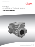
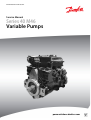
MAKING MODERN LIVING POSSIBLE
Service Manual
Series 40 M46
Variable Pumps
powersolutions.danfoss.com
Service Manual
Series 40 M46 Variable Pumps
Revision History
Table of Revisions
2
Date
Changed
Rev
April 2014
Danfoss layout
BA
October 2010
corrections to port location illustration
AE
March 2010
Fix Osaka address
AD
March 2009
added spool alignment illustration
AC
May 2008
Fixed the illustrations
AB
October 2007
First edition
AA
11026743 • Rev BA • April 2014
Service Manual
Series 40 M46 Variable Pumps
Contents
Introduction
Fluid and filter maintenance
Initial startup procedures
Overview..............................................................................................................................................................................................5
Warranty.............................................................................................................................................................................................. 5
General instructions........................................................................................................................................................................ 5
Remove the unit.......................................................................................................................................................................... 5
Keep it clean..................................................................................................................................................................................5
Replace all O-rings and gaskets............................................................................................................................................. 5
Safety precautions............................................................................................................................................................................5
Unintended machine movement..........................................................................................................................................6
Flammable cleaning solvents................................................................................................................................................. 6
Fluid under pressure.................................................................................................................................................................. 6
Personal safety............................................................................................................................................................................. 6
Hazardous material.................................................................................................................................................................... 6
Symbols used in Danfoss literature............................................................................................................................................6
Design...................................................................................................................................................................................................8
The system circuit.............................................................................................................................................................................8
The basic closed circuit............................................................................................................................................................. 8
Case drain and heat exchanger..............................................................................................................................................8
Pump schematic............................................................................................................................................................................... 9
Fluid and filter recommendations........................................................................................................................................... 10
Hazardous material.................................................................................................................................................................. 10
General ..............................................................................................................................................................................................11
Start-up procedure........................................................................................................................................................................ 11
Required tools and pressure measurements
Required tools................................................................................................................................................................................. 12
Port locations and gauge installation.....................................................................................................................................12
Troubleshooting
Adjustments
Overview........................................................................................................................................................................................... 13
Safety precautions......................................................................................................................................................................... 13
System noise or vibration........................................................................................................................................................... 13
System operating hot...................................................................................................................................................................13
System will not operate in one direction.............................................................................................................................. 14
System will not operate in either direction.......................................................................................................................... 14
Neutral difficult or impossible to find.....................................................................................................................................15
System response is sluggish...................................................................................................................................................... 15
Electrical troubleshooting.......................................................................................................................................................... 16
Standard procedures, inspections, and adjustments....................................................................................................... 17
Warranty............................................................................................................................................................................................17
Pump adjustment.......................................................................................................................................................................... 17
Charge pressure relief valve.......................................................................................................................................................17
Engaging the bypass function.................................................................................................................................................. 18
System check/relief (SCR) valves.............................................................................................................................................. 19
Displacement limiter adjustment............................................................................................................................................ 20
Swashplate neutral adjustment................................................................................................................................................21
Measured data........................................................................................................................................................................... 21
Pump Setup................................................................................................................................................................................ 21
Manual Displacement Control Neutral-Return Bracket Adjustment...........................................................................22
Measured data........................................................................................................................................................................... 22
Procedure.................................................................................................................................................................................... 22
Electric Displacement Control/Hydraulic Displacement Control Neutral Adjustment........................................ 23
Measured data........................................................................................................................................................................... 23
Procedure.................................................................................................................................................................................... 23
11026743 • Rev BA • April 2014
3
Service Manual
Series 40 M46 Variable Pumps
Contents
Minor repair
Torque chart
4
Standard procedures, removing the pump..........................................................................................................................25
Removal........................................................................................................................................................................................25
Inspection....................................................................................................................................................................................25
Reassembly................................................................................................................................................................................. 25
Displacement limiter.....................................................................................................................................................................25
Removal........................................................................................................................................................................................25
Inspection....................................................................................................................................................................................26
Reassembly................................................................................................................................................................................. 26
Pressure filtration adapter.......................................................................................................................................................... 26
Removal........................................................................................................................................................................................26
Inspection....................................................................................................................................................................................26
Reassembly................................................................................................................................................................................. 27
Charge pump...................................................................................................................................................................................27
Removal........................................................................................................................................................................................27
Inspection....................................................................................................................................................................................28
Reassembly................................................................................................................................................................................. 28
Shaft seal, roller bearing and shaft replacement................................................................................................................29
Removal........................................................................................................................................................................................29
Inspection....................................................................................................................................................................................29
Reassembly................................................................................................................................................................................. 30
SCR valves......................................................................................................................................................................................... 30
Removal........................................................................................................................................................................................30
Inspection....................................................................................................................................................................................30
Reassembly................................................................................................................................................................................. 30
Charge pressure relief valve.......................................................................................................................................................31
Removal........................................................................................................................................................................................31
Inspection....................................................................................................................................................................................31
Reassembly................................................................................................................................................................................. 31
Bypass valve..................................................................................................................................................................................... 32
Removal........................................................................................................................................................................................32
Inspection....................................................................................................................................................................................32
Reassembly................................................................................................................................................................................. 32
Manual displacement control....................................................................................................................................................33
Removal........................................................................................................................................................................................33
Inspection....................................................................................................................................................................................33
Reassembly................................................................................................................................................................................. 33
Electronic displacement control/hydraulic displacement control.............................................................................. 34
Removal........................................................................................................................................................................................34
Inspection....................................................................................................................................................................................35
Reassembly................................................................................................................................................................................. 35
MDC orifice repair.......................................................................................................................................................................... 35
Removal........................................................................................................................................................................................35
Inspection....................................................................................................................................................................................35
Reassembly................................................................................................................................................................................. 35
EDC/HDC orifice repair.................................................................................................................................................................36
Removal........................................................................................................................................................................................36
Inspection....................................................................................................................................................................................36
Reassembly................................................................................................................................................................................. 36
Fastener size and torque chart..................................................................................................................................................38
Plug size and torque chart..........................................................................................................................................................38
11026743 • Rev BA • April 2014
Service Manual
Series 40 M46 Variable Pumps
Introduction
Overview
This manual includes information for the installation, maintenance, and minor repair of the Series 40 M46
pump. It includes a description of the unit and its individual components, troubleshooting information,
and minor repair procedures.
Performing minor repairs requires the unit to be removed from the vehicle/machine. Thoroughly clean
the unit before beginning maintenance, or repair activities. Since dirt and contamination are the greatest
enemies of any type of hydraulic equipment, follow cleanliness requirements strictly. This is especially
important when changing the system filter and when removing hoses or plumbing.
A worldwide network of Danfoss Global Service Partners is available for major repairs. Danfoss trains
Global Service Partners and certifies their facilities on a regular basis. You can locate your nearest Global
Service Partner using the distributor locator at www.powersolutions.danfoss.com.
Warranty
Performing installation, maintenance, and minor repairs according to the procedures in this manual will
not affect your warranty. Major repairs requiring the removal of a unit’s front flange voids the warranty
unless done by a Danfoss Global Service Partner.
General instructions
Follow these general procedures when repairing Series 40 M46 variable displacement closed circuit
pumps.
Remove the unit
Prior to performing repairs, remove the unit from the vehicle/machine. Chock the wheels on the vehicle
or lock the mechanism to inhibit movement. Be aware that hydraulic fluid may be under high pressure
and/or hot. Inspect the outside of the pump and fittings for damage. Cap hoses and plug ports after
removal to prevent contamination.
Keep it clean
Cleanliness is a primary means of assuring satisfactory pump life, on either new or repaired units. Clean
the outside of the pump thoroughly before disassembly. Take care to avoid contamination of the system
ports. Cleaning parts using a clean solvent wash and air drying is usually adequate.
As with any precision equipment, keep all parts free of foreign materials and chemicals. Protect all
exposed sealing surfaces and open cavities from damage and foreign material. If left unattended, cover
the pump with a protective layer of plastic.
Replace all O-rings and gaskets
Danfoss reccommends you replace all O-rings, seals, and gaskets during repair. Lightly lubricate all Orings with clean petroleum jelly prior to assembly.
Safety precautions
Always consider safety precautions before beginning a service procedure. Protect yourself and others
from injury. Take the following general precautions whenever servicing a hydraulic system.
11026743 • Rev BA • April 2014
5
Service Manual
Series 40 M46 Variable Pumps
Introduction
Unintended machine movement
W
Warning
Unintended movement of the machine or mechanism may cause injury to the technician or bystanders.
To protect against unintended movement, secure the machine or disable/disconnect the mechanism
while servicing.
Flammable cleaning solvents
W
Warning
Some cleaning solvents are flammable. To avoid possible fire, do not use cleaning solvents in an area
where a source of ignition may be present.
Fluid under pressure
W
Warning
Escaping hydraulic fluid under pressure can have sufficient force to penetrate your skin causing serious
injury and/or infection. This fluid may also be hot enough to cause burns. Use caution when dealing with
hydraulic fluid under pressure. Relieve pressure in the system before removing hoses, fittings, gauges, or
components. Never use your hand or any other body part to check for leaks in a pressurized line. Seek
medical attention immediately if you are cut by hydraulic fluid.
Personal safety
W
Warning
Protect yourself from injury. Use proper safety equipment, including safety glasses, at all times.
Hazardous material
W
Warning
Hydraulic fluid contains hazardous material. Avoid prolonged contact with hydraulic fluid. Always
dispose of used hydraulic fluid according to state, and federal environmental regulations.
Symbols used in Danfoss literature
WARNING may result in injury
CAUTION may result in damage to product or property
Reusable part
Non-reusable part, use a new part
Non-removable item
Option – either part may exist
Superseded – parts are not interchangeable
6
11026743 • Rev BA • April 2014
Service Manual
Series 40 M46 Variable Pumps
Introduction
Measurement required
Flatness specification
Parallelism specification
External hex head
Internal hex head
Torx head
O-ring boss port
Tip, helpful suggestion
Lubricate with hydraulic fluid
Apply grease/petroleum jelly
Apply locking compound
Inspect for wear or damage
Clean area or part
Be careful not to scratch or damage
Note correct orientation
Mark orientation for reinstallation
Torque specification
Press in – press fit
Pull out with tool – press fit
Cover splines with installation sleeve
Pressure measurement/gauge location or specification
The symbols above appear in the illustrations and text of this manual. They are intended to communicate
helpful information at the point where it is most useful to the reader. In most instances, the appearance
of the symbol itself denotes its meaning. The legend above defines each symbol and explains its purpose.
11026743 • Rev BA • April 2014
7
Service Manual
Series 40 M46 Variable Pumps
Introduction
Design
Danfoss Series 40 M46 closed-circuit axial-piston pumps convert input torque into hydraulic power. The
input shaft transmits rotational force to the cylinder block. Bearings at the front and rear of the pump
support the input shaft. Splines connect the cylinder block to the input shaft. A lip-seal at the front end of
the pump prevents leakage where the shaft exits the pump housing. The spinning cylinder block
contains seven reciprocating pistons. A ball joint connects a brass slipper to each piston. A spring washer
and the force of charge pressure holds the slippers to the swashplate. The reciprocating movement of the
pistons occurs as the slippers slide against the inclined swashplate during rotation. Via the valve plate,
one half of the cylinder block connects to low pressure and the other half to high pressure. As each piston
cycles in and out of its bore, fluid displaces from inlet to outlet imparting hydraulic power into the
system. A small amount of fluid flows from the cylinder block/valve plate and slipper/swashplate
interfaces for lubrication and cooling. The pump also uses excess flow from the charge pressure relief
valve for cooling. Case drain ports return this fluid to the reservoir. A gerotor-style charge pump provides
this flow and maintains a minimum pressure in the system loop.
The angle of the swashplate controls the volume of fluid displaced into the system. The servo piston sets
swashplate angle. The pump control modulates servo piston position by varying differential pressure
across the piston.
Cross section view
Gerotor
Valve plate
Ball bearing
Piston
Slipper
Shaft
Shaft Seal
Journal Bearing
Swashplate bearing pin
Needle bearing
Servo piston
Cylinder block
Swashplate
Sleeve Bearing
Manual displacement Control
The system circuit
The basic closed circuit
Hydraulic lines connect the main ports of the pump to the main ports of the motor. Fluid flows in either
direction from the pump to the motor and back in this closed circuit. Either of the hydraulic lines can be
under high pressure. In pumping mode the angle of the pump swashplate determines which line is high
pressure as well as the direction of fluid flow.
Case drain and heat exchanger
The pump and motor require case drain lines to remove hot fluid from the system. The pump and motor
should be drained from their top most drain port to ensure the case remains full of fluid. Flow from the
motor case drain may route to the lower drain port on the pump housing and out the top most port, or
8
11026743 • Rev BA • April 2014
Service Manual
Series 40 M46 Variable Pumps
Introduction
feed directly to the heat exchanger. The system requires a heat exchanger with a bypass valve to cool the
case drain fluid before it returns to the reservoir.
System circuit diagram
Reservoir
Heat exchanger
bypass
Control
handle
Filter
Displacement
control
valve
Heat
exchanger
Cylinder
block
assembly
Cylinder
block
assembly
Variable
displacement
motor
Charge relief
valve
Bypass
valve
Output
shaft
Charge
pump
Input
shaft
Variable
displacement
pump
Loop flushing
module
Suction flow
Check valves
w/ high pressure
relief valve
Charge pressure
Servo pressure
High pressure
Case flow
P106 608E
Pump schematic
Pump schematic
BNA
E
M3
A
M4
M1
M5
L2
M2
B
L1
S
P100 587E
Above schematic shows the function of a Series 40 M46 axial piston variable displacement pump.
11026743 • Rev BA • April 2014
9
Service Manual
Series 40 M46 Variable Pumps
Fluid and filter maintenance
Fluid and filter recommendations
To ensure optimum life, perform regular maintenance of the fluid and filter. Contaminated fluid is the
main cause of unit failure. Take care to maintain fluid cleanliness when servicing.
Check the reservoir daily for proper fluid level, the presence of water, and rancid fluid odor. Fluid
contaminated by water may appear cloudy or milky, or free water may settle in the bottom of the
reservoir. Rancid odor indicates the fluid was exposed to excessive heat. Change the fluid immediately if
these conditions occur. Correct the problem immediately. Inspect vehicle for leaks daily.
Change the fluid and filter per the vehicle/machine manufacturer’s recommendations or at these
intervals:
We recommend first fluid change at 500 hours.
C Caution
High temperatures and pressures accelerate fluid aging. More frequent fluid changes may be required.
Change the fluid more frequently if it becomes contaminated with foreign matter (dirt, water, grease,
etc.) or if the fluid is subjected to temperature levels greater than the recommended maximum.
Dispose of used hydraulic fluid properly. Never reuse hydraulic fluid.
Change filters whenever you change the fluid or when the filter indicator shows that it is necessary to
change the filter. Replace all fluid lost during filter change.
Fluid and filter change interval
Reservoir type
Max oil change interval
Sealed
2000 hours
Breather
500 hours
Hazardous material
W
Warning
Hydraulic fluid contains hazardous material. Avoid contact with hydraulic fluid. Always dispose of used
hydraulic fluid according to state, and federal environmental regulations.
10
11026743 • Rev BA • April 2014
Service Manual
Series 40 M46 Variable Pumps
Initial startup procedures
General
Follow this procedure when starting-up a new pump installation or when restarting an installation in
which the pump was removed. Ensure pump is thoroughly tested on a test stand before installing.
W
Warning
Unintended movement of the machine or mechanism may cause injury to the technician or bystanders.
To protect against unintended movement, secure the machine or disable/disconnect the mechanism
while servicing.
Prior to installing the pump, inspect for shipping damage.
Start-up procedure
1. Ensure the machine hydraulic oil and system components (reservoir, hoses, valves, fittings, and heat
exchanger) are clean and free of any foreign material.
2. Install new system filter element(s) if necessary. Check that inlet line fittings are properly tightened
and there are no air leaks.
3. Install the pump. Install a 50 bar [1000 psi] gauge in the charge pressure gauge port M
4. Fill the housing by adding filtered oil in the upper case drain port. Replace plug.
5. Fill the reservoir with hydraulic fluid of the recommended type and viscosity. Use a 10-micron
reservoir filler filter. Ensure inlet line from reservoir to pump is filled.
6. Disconnect the pump from all control input signals.
After start-up the oil level in the reservoir may drop due to filling of the system components. Check
the level in the reservoir to maintain a full oil level throughout start-up.
W Warning
Damage to hydraulic components may occur if you fail to maintain the oil supply.
7. Use a common method to disable the engine to prevent it from starting. Crank the starter for several
seconds. Do not to exceed the engine manufacturer’s recommendation. Wait 30 seconds and then
crank the engine a second time as stated above. This operation helps remove air from the system
lines. Refill the reservoir to recommended full oil level.
8. Check the pressure gauge at M3. When charge pressure begins to build, enable and start engine. Let
the engine run for a minimum of 30 seconds at low idle to allow the air to work itself out of the
system. Check for leaks at all line connections and listen for cavitation. Check for proper fluid level in
reservoir.
C
Caution
Air entrapment in oil under high pressure may damage hydraulic components. Do not run at
maximum pressure until system is free of air and fluid has been thoroughly filtered.
9. When the pump estabishes adequate charge pressure (as shown in model code), increase engine
speed to normal operating rpm to further purge residual air from the system.
10. Shut off engine. Connect pump control signal. Start engine, checking to be certain pump remains in
neutral. Run engine at normal operating speed and carefully check for forward and reverse control
operation.
11. Continue to cycle between forward and reverse for at least five minutes to bleed all air and flush
system contaminants out of loop.
Normal charge pressure fluctuation may occur during forward and reverse operation.
12. Check that the reservoir is full. Remove charge pressure gauge. Re-intall charge pressure plug. The
pump is now ready for operation.
11026743 • Rev BA • April 2014
11
Service Manual
Series 40 M46 Variable Pumps
Required tools and pressure measurements
Required tools
The service procedures described in this manual can be performed using common mechanic’s hand
tools. Special tools, if required, are shown. When testing system pressures, calibrate pressure gauges
frequently to ensure accuracy. Use snubbers to protect gauges.
Port locations and gauge installation
The following tables and drawing show the port locations and gauge sizes needed.
Port information
Port identifier
Port size
Wrench size
Pressure obtained
Gauge size, bar [psi]
L1, L2
1-1/16 12 SAE
9/16 internal hex
Case drain
10 [150]
MA, MB
9/16 18 SAE
11/16 hex
System pressure
600 [9,000]
M3
9/16 18 UNF
11/16 hex
Charge pressure
50 [750]
M4, M5
9/16 18 SAE
11/16 hex
Servo pressure
50 [750]
System valves
Port identifier
Relief
Port size
Wrench size
RA
A port pressure relief valve
1-5/16 12 UNF
1-1/4 hex
RB
B port pressure relief valve
1-5/16 12 UNF
1-1/4 hex
R
Charge pressure relief valve
3/4 16 UNF
7/8 hex
BP
Bypass valve
5/8 18 UNF
1 inch hex
System ports
Port identifier
Port size
A system pressure port
1-5/16 12 SAE
B system pressure port
1-5/16 12 SAE
S (charge pressure inlet)
1-5/16 12 SAE
Port locations
MA
MB
M3
RB
L1
M4
M5
R
B
L2
P106 604E
12
11026743 • Rev BA • April 2014
RA
BP
A
S
Service Manual
Series 40 M46 Variable Pumps
Troubleshooting
Overview
This section provides general steps to follow if undesirable system conditions occur. Follow these steps
until you solve the problem. Some of the items are system specific. For areas this manual covers, we
reference the section. Always observe the safety precautions in Introduction on page 5 and those related
to your specific equipment.
Safety precautions
C Caution
High inlet vacuum causes cavitation which can damage internal pump components. Ensure charge pump
supply plumbing is adequate. Locating pump below the level of the reservoir, when possible, improves
inlet conditions.
C Caution
Contamination can damage internal components and void the manufacturer’s warranty. Take
precautions to ensure system cleanliness when removing and reinstalling system lines
System noise or vibration
Item
Description
Action
Reservoir oil level
Low oil level leads to cavitation.
Fill reservoir.
Aeration of the oil/pump inlet vacuum
Air in system decreases efficiency of units and
controls. Excessive noise, foaming oil, and heat may
indicate air in system.
Find location where air is entering into the
system and repair leak.
Check that inlet line is not restricted and is the
proper size.
Cold oil
Cold oil may be too viscous for proper function:
pump cavitates.
Allow the oil to warm up to it’s normal operating
temperature with engine at idle speed.
Pump inlet vacuum
High inlet vacuum causes noise/cavitation.
Check that inlet line is not restricted and is the
proper size.
Check filter and bypass valve.
Shaft couplings
A loose shaft coupling causes excessive noise.
Replace loose shaft coupling. Replace pump
shaft.
Shaft alignment
Misaligned shafts creates noise.
Align shafts.
Charge/system relief valves
Unusual noise may indicate sticking valves, possible
contamination.
Clean/replace valves and test pump. May be a
normal condition.
System operating hot
Item
Description
Action
Oil level in reservoir
Insufficient hydraulic fluid will not meet the
cooling demands of system.
Fill the reservoir to the proper level with clean
hydraulic oil.
Heat exchanger (if equipped)
The heat exchanger is not sufficiently cooling the
system.
Check the air flow and input air temperature for
the heat exchanger. Clean, repair, or replace the
heat exchanger as necessary.
Heat exchanger bypass valve
A partially activated heat exchanger bypass valve
may result in heat generation within the system.
Verify that the bypass valve is fully closed and that
the valve is seating properly. Repair or replace as
necessary.
SCR (System Check / Relief) Valves
A partially activated SCR valve or SCR valves with
relief settings too low may generate heat within
the system.
Verify that the SCR valve is seating properly and is
at the correct relief setting. Repair or replace it as
necessary.
Oil filters
Clogged oil filters may result in an insufficient
supply of cool oil to the system.
Inspect the oil filters and verify that they are still
operable. Replace them if necessary.
11026743 • Rev BA • April 2014
13
Service Manual
Series 40 M46 Variable Pumps
Troubleshooting
Item
Description
Action
Machine load
Excessive loads or extreme duty cycles can result in Verify that the machine is operating within the
the pump and/or motor operating at speeds and
parameters for which it was designed. If necessary,
pressures beyond system design limitations.
reduce the load on the machine.
System will not operate in one direction
Item
Description
Action
Input control signal (linkage, current, or
pressure)
A faulty control signal is being received at the
pump. (MDC - binding or broken linkage, EDC faulty or inadequate electrical signal, HDC blocked or incorrectly orificed control lines).
Verify that the input signal being received is
correct and identical in both directions. Adjust,
clean, repair, or replace the control module as
necessary.
Displacement limiters (if equipped)
The displacement limiters may be improperly
adjusted such that the servo piston is prevented
from moving in one direction.
Verify that the displacement limiters are adjusted
properly.
SCR (system check / relief) valves
The SCR valves are malfunctioning or improperly
set.
Verify that the SCR valves are operating properly.
Repair or replace them as necessary.
Pump control
A damaged or biased pump control may be
sending a signal commanding the pump to stroke
only in one direction.
Verify that the pump’s control is functioning
properly. Repair or replace it as necessary.
Servo pressure
The drain or supply path to one side of the servo
piston may be blocked.
Verify that the servo supply and drain paths are
unobstructed and that each orifice is of the correct
size and free of debris. Clean or repair them as
necessary.
System will not operate in either direction
Item
Description
Action
Oil level in reservoir
There is insufficient hydraulic fluid to supply the
system loop.
Fill the reservoir to the proper level with clean
hydraulic oil.
Displacement limiters
Displacement limiters may be improperly adjusted
such that the servo piston is locked in place.
Verify that the displacement limiters are adjusted
to the proper setting.
Input control signal
(linkage, current, or pressure)
A faulty control signal being received at the pump.
(MDC - binding or broken linkage, EDC - faulty or
inadequate electrical signal, HDC - blocked or
incorrectly orificed control lines)
Verify that the input signal being received is
correct and identical in both directions. Adjust,
clean, repair, or replace the input device as
necessary.
Oil filters
Clogged oil filters may result in an insufficient
supply of oil to the system.
Inspect the oil filters and verify that they are still
serviceable. Replace them as necessary.
Bypass valve
A partially activated bypass valve (one or both)
may result in a cross port leakage.
Verify that the bypass valves are closed and that
the valves are seating properly. Clean, repair, or
replace them as necessary.
Charge pressure
(in neutral)
Charge pressure may be insufficient to recharge
the system loop.
Inspect the charge pump for damage and verify
that the charge pressure relief valve is at the proper
setting. Repair or replace it as necessary.
Charge pressure
(in stroke)
There is low charge pressure resulting from internal Repair or replace the component or components
leakage within the system.
within the system causing the internal leakage.
Servo pressure
There is an insufficient pressure differential across
the servo piston.
14
11026743 • Rev BA • April 2014
Check servo pressures to verify sufficient pressure
delta. Verify that the servo supply and drain paths
are unobstructed and that each orifice is of the
correct size and free of debris. Clean, repair, or
replace them as necessary.
Service Manual
Series 40 M46 Variable Pumps
Troubleshooting
Item
Description
Action
Charge pump
The charge pump is damaged or has been installed Verify that the charge pump is in good working
with the incorrect rotational orientation.
order and that it is correctly installed. Repair or
replace it as necessary.
SCR (system check / relief) valves
The SCR valves are malfunctioning or improperly
set.
Verify that the SCR valves are operating and
properly set. Repair or replace them as necessary.
Item
Description
Action
Input control signal (linkage, current, or
pressure)
A faulty control signal is being received at the
pump. (MDC - binding or broken linkage, EDC faulty or inadequate electrical signal, HDC blocked or incorrectly orificed control lines)
Verify that the input signal being received is
correct and identical in both directions. Adjust,
clean, repair, or replace control module as
necessary.
System pressure
With no input signal to the control, a pressure delta Readjust pump neutral setting. Refer to Swashplate
may exist between the two sides of the working
neutral adjustment on page 21.
loop.
Servo pressure
With no input signal to the control, a pressure delta Readjust the control neutral setting. Refer to
may exist across the servo piston.
Manual Displacement Control Neutral-Return Bracket
Adjustment on page 22 and Electric Displacement
Control/Hydraulic Displacement Control Neutral
Adjustment on page 23
PCP pressure (EDCs only)
With no input signal to the control, a pressure
difference may exist across the control spool.
Neutral difficult or impossible to find
Replace the EDC.
System response is sluggish
Item
Description
Action
Reservoir oil level
There is an insufficient amount of hydraulic fluid,
resulting in an inadequate supply for the system
loop.
Fill the reservoir to the proper level with clean
hydraulic fluid.
Input control signal
(linkage, current, or pressure)
A faulty control signal is being received at the
pump. (MDC - binding or broken linkage; EDC faulty or inadequate electrical signal; HDC blocked or incorrectly orificed control lines)
Verify that the input signal being received is correct
and identical in both directions.
Pump control
A damaged pump control or control spool will not
correctly transmit the control input signal to the
pump.
Verify that the pump’s control is operating properly
and that the control spool is not damaged or worn
and moves freely within its bore. Clean, repair, or
replace it as necessary.
Bypass valve
A partially activated bypass valve causes cross port
leakage.
Verify that the bypass valve is closed and that the
valve is seating properly. Clean, repair, or replace it as
necessary.
SCR (system check / relief) valves
One or both of the SCR valves may be binding
within their bores.
Verify that the SCR valves operate freely. Repair or
replace them as necessary.
Charge pressure (in neutral)
There is low charge pressure resulting from a
damaged charge pump or low charge pressure
relief valve setting.
Inspect the charge pump for damage and verify the
charge pressure relief valve setting. Repair or replace
as necessary.
Charge pressure (in stroke)
There is low charge pressure resulting from internal Repair or replace the component or components
leakage within the system.
within the system causing the internal leakage.
Servo pressure
There is insufficient pressure differential across the
servo piston.
11026743 • Rev BA • April 2014
Check servo pressures at port M4 and M5 to verify
sufficient pressure delta. Verify that the servo supply
and drain paths are unobstructed and that each
15
Service Manual
Series 40 M46 Variable Pumps
Troubleshooting
Item
Description
Action
orifice is of the correct size and free of debris. Clean,
repair, or replace as necessary.
Charge pump
The charge pump has been damaged or installed
with the incorrect rotational orientation.
Verify that the charge pump is in good working order
and that it is correctly installed. Repair or replace it as
necessary.
Electrical troubleshooting
Item
Description
Action
Control operates pump in one direction
only
Control coil had failed (EDC).
Measure resistance at coil pins. Resistance should be
14.20 ohms (24V) or 3.66 ohms (12V) at 20°C [70°F].
Replace coil.
No pump function
No power to controller.
Restore power to controller.
Erratic pump function
Electrical connection to pump is bad.
Disconnect connection, check wires, reconnect
wires.
Filter bypass indicator switch
Filter switch may be bad.
Check/replace filter switch. Add gauge to filter
bypass port to verify proper fluid flow and verify
switch operation by measuring resistance.
open resistance=>510 ohms, closed
resistance<=122 ohms.
16
11026743 • Rev BA • April 2014
Service Manual
Series 40 M46 Variable Pumps
Adjustments
Standard procedures, inspections, and adjustments
Before working on the pump, clean all dirt and grime from the outside of the pump and surrounding
area.
C
Caution
Contamination can damage internal components and void the manufacturer’s warranty. Take
precautions to ensure system cleanliness when removing and reinstalling system lines.
1. If removing the pump, tag each hydraulic line. If you disconnect hydraulic lines, plug each open port
to ensure that dirt and contamination do not get into the pump.
2. Inpect the hydraulic fluid for signs of system contamination, oil discoloration, foam in the oil, sludge,
or small metal particles.
3. If there are signs of contamination in the hydraulic fluid, replace all filters and drain and clean the
hydraulic system. Fill with the correct hydraulic fluid.
4. Flush the lines before replacing the hydraulic fluid.
5. Before re-installing the pump, test for leaks.
Warranty
Performing installation, maintenance, and minor repairs according to the procedures in this manual will
not affect your warranty. Major repairs requiring the removal of a unit’s front flange voids the warranty
unless done by a Danfoss Global Service Partner.
Pump adjustment
This section offers instruction on adjustment of pump components. Read through the entire topic before
beginning a service activity. Refer to Port locations and gauge installation on page 12, for location of
gauge ports and suggested gauge size.
Charge pressure relief valve
This procedure explains how to check and adjust the charge pressure relief valve.
1. Install a 50 bar [1000 psi] pressure gauge in charge pressure gauge port M3. Install a 10 bar [100 psi]
gauge in one of the case pressure ports L1 or L2. Operate the system with the pump in neutral (zero
displacement) when measuring charge pressure.
2. To adjust charge pressure, shut down system.
3. Using a 1 inch hex wrench, remove charge pressure relief plug (102). Add or remove shims (101) in
relief valve. Adding shims increases charge pressure, while removing shims decreases charge
pressure.
4. Lubricate and install new O-ring (103).
5. Using a 1 inch hex wrench, reinstall plug. Torque to 108 N•m [80 lbf•ft].
6. Operate pump in neutral to verify proper charge setting. Charge pressure is referenced to case
pressure. Subtract case pressure (L1/L2) from charge pressure (M3) to compute actual setting. Repeat
steps 1-5 if necessary.
7. Remove gages and replace plugs (M3, L1/L2). Using an 11/16 in. hex wrench, torque plug (M3) to 37
N•m [27 lbf•ft]. Using a 9/16 in. internal hex wrench, torque plug (L1/L2) to 115 N•m [85 lbf•ft].
11026743 • Rev BA • April 2014
17
Service Manual
Series 40 M46 Variable Pumps
Adjustments
Charge pressure adjustment
103
102
1 in.
101
104
105
M3
11/16 in
Charge pressure
gage port
P106 634E
Engaging the bypass function
Test bypass function with pump installed on machine. The bypass function is engaged by unscrewing the
bypass valve. Do not open the bypass valve when machine is operating.
1. To engage the bypass function, use a 5/8 in. hex wrench to unthread the bypass valve.Rotate the
bypass valve approximately three turns counterclockwise. Do not rotate more than 3 revolutions:
additional rotation permits external leakage.
2. To close the bypass valve, rotate the bypass valve clockwise until seated. Torque to 20 N•m [15 lbf•ft].
3. Vehicle/machine should move with bypass valve open. Close valve for normal operation.
C Caution
Bypass valve is not a tow-valve. Damage to pump and motor is possible when operating without
charge pressure. Limit speed of movement to 20% of the vehicle/machine’s maximum for no longer
than 3 minutes.
18
11026743 • Rev BA • April 2014
Service Manual
Series 40 M46 Variable Pumps
Adjustments
Using the bypass function
Bypass check valve
5/8 in
P106 633E
System check/relief (SCR) valves
The SCR valve is a high pressure relief valve and a system check valve in combination. Whenever an SCR
valve is replaced or opened, opperate the pump in its full range of functions to ensure proper machine
operation. The SCR valves are pre-set at the factory, no adjustment is possible. Pressure code is marked
on the valve. Refer to the model code for pressure designation. If you suspect SCR malfunction, replace
valve and test operation of pump.
This procedure explains how to replace the SCR valves.
1. Shut down the system.
2. Using a 1-1/4 in. hex wrench, remove relief valve plug (166).
3. Remove spring (165) and relief valve (1103) from pump housing.
4. Insert new relief valve and spring into pump housing.
5. Lubricate and install new O-ring (106).
6. Using a 1-1/4 in. hex wrench, install relief valve plug. Torque to 176 N•m [130 lbf•ft].
11026743 • Rev BA • April 2014
19
Service Manual
Series 40 M46 Variable Pumps
Adjustments
Installing the SCRs
166
1-1/4 in
176 Nm [130 ft•lb]
106
165
1103
1103
165
106
166
1-1/4 in
176 Nm [130 ft•lb]
P106 635E
Displacement limiter adjustment
Pump may have a displacement limiter on each side of the servo. Each limiter may be adjusted to a
different setting.
1. Remove snap ring (928) and sleeve (929).
2. Using a flat screw driver to hold the displacement limiter, loosen the locking nut (927) with a 9/16 hex
wrench.
3. Rotate the displacement limiter (911) to adjust maximum displacement. Rotating the adjusting screw
clockwise decreases the maximum displacement of the pump while rotating the adjusting screw
counterclockwise increases the maximum displacement. The displacement changes approximately 4
cm³ per revolution.
4. After establishing the desired maximum displacement setting, hold displacement limiter in place
using a flat screw driver and tighten the locking nut with a 9/16 in. hex wrench. Torque to 12 N•m [9
lbf•ft]. Repeat if necessary to adjust maximum displacement in other direction.
5. After adjustment, verify proper maximum vehicle/machine speed. Readjust if necessary.
20
11026743 • Rev BA • April 2014
Service Manual
Series 40 M46 Variable Pumps
Adjustments
Displacement limiter adjustment
929
928
927
9/16 in
911
P106 626E
Swashplate neutral adjustment
With the pump properly plumbed, primed, and mounted on a vehicle or test stand, use this procedure to
adjust mechanical neutral. If pump is on a vehicle, securely block the wheels to prevent movement.
Measured data
•
•
•
System pressure at MA
System pressure at MB
Pressure differential between MA and MB (optional)
Pump Setup
1. Attach 600 bar [10,000 psi] gauge to system pressure gage ports MA and MB.
2. Using a hydraulic line and fittings, shunt the servo piston by connecting servo pressure ports (M4 and
M5).
Connecting servo ports M4 and M5 defeats the affect of any control pressure on the servo piston.
3. Run prime mover at normal operating speed.
4. Use a 1/4 hex wrench to hold adjusting screw (908) in place and a 9/16 hex wrench to loosen servo
lock nut (115).
5. Turn neutral adjustment screw (908) until one system pressure gage begins to show an increase in
pressure. Note position of screw. Turn the neutral adjustment screw (908) in the opposite direction
until the other system pressure gage begins to show an increase in pressure. Note position of screw.
Turn the neutral adjustment screw half way between the two postitions.
11026743 • Rev BA • April 2014
21
Service Manual
Series 40 M46 Variable Pumps
Adjustments
6. Use a 1/4 hex wrench to hold the servo adjustment screw in place, and a 9/16 hex wrench to tighten
servo lock nut (115). Torque to 37 N•m [27 lbf•ft].
7. Shut down prime mover and remove previously installed gauges and fittings. Plug ports MA, MB, M4,
and M5.
Servo neutral adjustment
908
Connect Ports
M4 and M5
1/4 in
115
P106 630E
11/16 in
Manual Displacement Control Neutral-Return Bracket Adjustment
With the pump properly plumbed, primed, and mounted on a vehicle or test stand, use the following
procedure to adjust the pump displacement control to neutral position. If pump is on a vehicle, securely
block the wheels to prevent movement. Check swashplate mechanical neutral adjustment before
adjusting control bracket. Refer to previous topic Swashplate neutral adjustment on page 21 for
instructions. If swashplate neutral is properly adjusted and system is not in neutral, adjust MDC bracket as
described below.
Measured data
•
•
•
Servo pressure at M4
Servo pressure at M5
Pressure differential between M4 and M5 (optional)
Procedure
1. Attach 20 bar [300 psi] gauge to each servo gage port M4 and M5. Run prime mover at normal
operating speed.
2. Using a 3/8 in. hex wrench, loosen screw (1210) allowing the neutral bracket to move, but not freely.
3. Start prime mover and slowly accelerate to normal operating rpm.
4. Using your hand, press neutral bracket towards the pump housing, and rotate it until one of the servo
pressure gages indicates an increase in pressure. Note position of bracket. Rotate neutral bracket in
opposite direction until the other servo pressure gage indicates an increase in pressure. Note position
of bracket. Rotate neutral bracket half way between the two positions.
5. Holding the neutral adjustment bracket in place, use a 3/8 in. hex wrench to tighten screw (1210).
Torque to 14 N•m [10 lbf•ft].
22
11026743 • Rev BA • April 2014
Service Manual
Series 40 M46 Variable Pumps
Adjustments
6. Shut down prime mover and remove previously installed gauges. Plug ports M4, M5. Torque to 37
N•m [27 lbf•ft]
Manual displacement control bracket adjustment
1210
3/8 in
Neutral bracket
P106 631E
Electric Displacement Control/Hydraulic Displacement Control Neutral Adjustment
With the pump properly plumbed, primed, and mounted on a vehicle or test stand, use this procedure to
adjust the pump displacement control to neutral position. If pump is on a vehicle, block the wheels to
prevent movement.
Measured data
•
•
•
Servo pressure at M4
Servo pressure at M5
Pressure differential between M4 and M5 (optional)
Procedure
1. Attach 20 bar [300 psi] gauge to each servo gage port.
2. Use a 5/32in. internal hex wrench to hold the adjusting screw in place and a 1/2 hex wrench, loosen
locknut.
3. Start prime mover and slowly accelerate to normal opperating rpm.
4. Rotate adjustment screw until one of the servo pressure gages indicates an increase in pressure. Note
position of screw. Rotate adjustment screw in opposite direction until the other servo pressure gage
indicates an increase in pressure. Note position of screw. Rotate adjustment screw halfway between
the two positions.
5. While holding the neutral adjustment screw in place, tighten locknut. Torque to 3 N•m [27 lbf•in].
6. Stop prime mover and remove previously installed gauges. Plug ports M4, M5. Torque to 37 N•m [27
lbf•ft]
11026743 • Rev BA • April 2014
23
Service Manual
Series 40 M46 Variable Pumps
Adjustments
EDC / HDC control adjustment
Adjustment screw
5/32 in
Lock nut
9/16 in
P106 643
24
11026743 • Rev BA • April 2014
Service Manual
Series 40 M46 Variable Pumps
Minor repair
Standard procedures, removing the pump
Before working on the pump, clean all dirt and grime from the outside.
If the pump has an auxiliary pump attached, remove both pumps as a single unit.Tag all hydraulic lines as
they are disconnected and plug all open ports to ensure that dirt and contamination do not get into the
pump.
C
Caution
Contamination can damage internal components and void the manufacturer’s warranty. Take
precautions to ensure system cleanliness when removing and reinstalling system lines.
Removal
1. With the prime mover off, thoroughly clean all dirt and grime from the outside of the pump.
2. Tag and disconnect each hydraulic line connected to the pump. As hydraulic lines are disconnected,
plug each open port, to ensure that dirt and contamination do not get into the pump.
3. Remove the pump and its auxiliary pump (if applicable) as a single unit.
C Caution
Be careful not to damage solenoids and electrical connections when using straps or chains to remove
pump from machine.
Inspection
1. Ensure the work surface and surrounding area are clean and free of contaminants such as dirt and
grime.
2. Inspect the hydraulic fluid for signs of system contamination, oil discoloration, foam in the oil, sludge,
or small metal particles.
Reassembly
1. Before replacing the pump on the machine, replace all filters and drain the hydraulic system. Fill the
system with the correct, filtered, hydraulic fluid.
2. Flush the lines before replacing the hydraulic fluid.
For repair part information, see Danfoss publication Series 40 M46 Variable Pump Parts Manual
BLN-2-41701 for your model.
Displacement limiter
Removal
Only remove displacement limiter (911) if replacement is necessary. Mark the location of displacement
adjustment and neutral adjustment screws before disassembly. This saves time during re-assembly.
1. Remove snap ring (928) and sleeve (929). Use a 1/4 in. hex wrench to hold neutral adjustment screw
in place. Use a 9/16 in. hex wrench to remove hex nut (115).
2. Use a flat screw driver to hold displacement limiter (911) in place. Use a 9/16 in. hex wrench to
remove lock nut (927).
3. Using a 3/8 in. hex wrench, remove five bolts (921) from servo cover (902).
4. Unscrew servo cover (902) to remove it from neutral adjustment screw. Remove and discard gasket
(936).
5. Turn displacement limiter (911) out of servo cover (902).
11026743 • Rev BA • April 2014
25
Service Manual
Series 40 M46 Variable Pumps
Minor repair
Inspection
Inspect all parts for damage. Inspect the mating surfaces of the servo cover (902) and pump housing
for scratches, grooves, and other damage. Inspect threads of screws and nuts for damage. Replace
any damaged parts.
Reassembly
1. Turn displacement limiter (911) into servo cover (902). Install new gasket (936) and turn servo cover
(902) onto neutral adjustment screw.
2. Using a 3/8 in. hex wrench, install five bolts (921). Torque to 15 N•m [11 lbf•ft].
3. Adjust displacement limiter to position originally noted during disassembly. Use a flat screw driver to
hold displacement limiter. Use a 9/16 in. hex wrench to install seal nut (927) onto displacement
limiter (911). Torque to 12 N•m [9 lbf•ft].
4. Set neutral adjustment screw at the position noted during disassembly. Use a 1/4 in. hex wrench to
hold neutral adjustment screw and a 9/16 in. hex wrench to install hex nut (115). Torque to 37 N•m
[27 lbf•ft]. Install sleeve (929) and snap ring (928).
Displacement limiter removal/installation
927
929
9/16 in
928
921
Servo neutral
adjustment screw
3/8 in
911
115
9/16 in
936
902
P106 641E
Pressure filtration adapter
Removal
1. Using an 11/16 in. hex wrench, remove plug (810). Remove and discard O-ring (810A).
2. Using a 1/2 in. hex wrench, remove screws (806).
3. Remove pressure filtration cover (801). Remove and discard seal adapter (805).
Inspection
Inspect the machined surface on the control. If any nicks or scratches are found, replace the damaged
component.
26
11026743 • Rev BA • April 2014
Service Manual
Series 40 M46 Variable Pumps
Minor repair
Reassembly
1. Install new seal adapter (805) and filtration cover (801).
2. Using a 1/2 hex wrench, install three screws (806). Torque to 30 N•m [22 lbf•ft].
3. Lubricate and install O-ring (810A) onto plug (810). Using an 11/16 in. hex wrench, install plug (810).
Torque to 37 N•m [27 lbf•ft].
Pressure filtration adapter removal/installation
805
801
810
11/16 in
810A
806
1/2 in
P106 642E
Charge pump
Removal
If a gear pump is attached to the auxiliary pad, remove the gear pump and O-ring or gasket.
1. Using a 9/16 in. hex wrench, remove screws (1506) and cover plate (1505). Remove and discard seal
(1504).
2. Using a 9/16 in. hex wrench, remove screws (1502). Remove auxiliary pad (1503).
3. Remove and discard O-ring (141) and load ring (142).
4. Remove gerotor cover (155) and gerotor (603).
5. Remove pin (604) and key (605).
11026743 • Rev BA • April 2014
27
Service Manual
Series 40 M46 Variable Pumps
Minor repair
Charge pump removal/installation
1506
9/16 in
77Nm [57 ft•lb]
1502
9/16 in
43Nm [32 ft•lb]
1503
142
1505
1504
141
155
604
603
605
P106 636E
Inspection
Inspect the gerotor (603) and gerotor cover (155) for wear, scratches or pitting. If any component
shows signs of wear, scratching, or pitting, relpace all components. Inspect pin (604) and key (605) for
damage, and replace parts if necessary. Replace O-ring (141), load ring (142), and seal (1504)
whenever charge pump is disassembled.
Reassembly
Charge pump parts are available as a complete set
1. Install key (605). Lubricate and install gerotor assembly (603).
2. Install pin (604) and gerotor cover (155).
3. Lubricate and install new O-ring (141) and load ring (142). Install auxiliary pad (1503).
4. Using a 9/16 in. hex wrench, install screws (1502). Torque to 43 N•m [32 lb•ft].
5. Lubricate and press seal (1504) onto auxiliary pad (1503).
If a gear pump is a ttached to the auxiliary pad, install a new O-ring or gasket and gear pump
6. Install cover plate (1505). Using a 9/16 in. hex wrench, install capscrews (1506). Torque to 77 N•m [57
lbf•ft].
If a gear pump is attached, seal (1504), cover (1505), and bolts (1506) are not used. Replace O-ring or
gasket between gear pump and M46 pump.
28
11026743 • Rev BA • April 2014
Service Manual
Series 40 M46 Variable Pumps
Minor repair
Shaft seal, roller bearing and shaft replacement
The shaft assembly is serviceable without removing the front cover of the pump, but the charge pump
must be removed first. Orient the pump on the work surface so the shaft is pointing up with the charge
pump (603) and key (605) removed from shaft. See Charge pump on page 27
Removal
1. Using a snap-ring pliers, remove snap-ring (132) from pump cover. Remove and discard seal (301).
Remove second snap-ring (132).
2. Remove shaft assembly from pump cover.
C Caution
Do not damage the housing bore, shaft, or bearing when removing the shaft and shaft seal.
3. Using a snap ring pliers, remove both snap-rings (133). Press bearing (131) off of shaft.
C Caution
Do not rotate or move pump after removing shaft. Internal components may be dislodged making
shaft replacement impossible without complete disassembly.
Shaft assembly
301
132
132
133
131
133
401
P106 637E
Inspection
Inspect the shaft and bearing for wear, scratching and pits. If wear, scratching or pitting is found,
replace the shaft and bearing. Rotate bearing while feeling for roughness. Replace bearing if it
doesn’t spin freely.
11026743 • Rev BA • April 2014
29
Service Manual
Series 40 M46 Variable Pumps
Minor repair
Reassembly
1. Using a snap ring pliers, install snap-ring (133 ). Lubricate and press bearing (131) onto shaft. Install
second snap-ring (133).
2. Install shaft and bearing assembly into front cover. Rotate shaft to align with block-splines. Ensure
bearing is installed deep enough to clear snapring groove.
3. Using a snap ring pliers, install snapring (132).
4. Cover shaft splines with an installation sleeve to protect lipseal during installation. Lubricate and
press new seal (301) into pump cover.
5. Install second snap-ring (132). Remove installation sleeve.
Shaft seal installation tool
7 in
0.750 in
1.24 in
2.75 in
0.370 in
1.5 in
2.45 in
3 in
P106 652E
SCR valves
The SCR valves are factory set and are not field adjustable.
Removal
1. Using a 1-1/4 in. hex wrench, remove relief valve plug (166). Remove and discard Oring (106).
2. Remove spring (165) and relief valve (1103) from pump housing.
Inspection
Inspect the sealing surfaces of the pump for nicks or scratches. Inspect the relief valve (1103) sealing
surface for nicks or scratches. If the relief valve (1103) is damaged, replace it.
Reassembly
1. Lubricate and insert relief valve (1103) and spring (165) into pump housing.
2. Lubricate and install new O-ring (106) onto plug (166). Using a 1-1/4 in. hex wrench install relief valve
plug (166). Torque to 176 N•m [130 lbf•ft].
30
11026743 • Rev BA • April 2014
Service Manual
Series 40 M46 Variable Pumps
Minor repair
SCR valves
166
1-1/4 in
176 Nm [130 ft•lb]
106
165
1103
1103
165
106
166
1-1/4 in
176 Nm [130 ft•lb]
P106 635E
Charge pressure relief valve
Replace the charge pressure relief valve components if they are damaged or if you suspect failure. See
Charge pressure relief valve on page 17, for adjustment instructions.
Removal
1. Using a 1 inch hex wrench, remove charge pressure relief plug (102). Remove and discard O-ring
(103).
2. Remove shims (101), spring (104), and charge pressure relief valve (105).
Inspection
Inspect the sealing surfaces of the pump for nicks or scratches. Inspect the relief valve (105) sealing
surface for nicks or scratches. If the relief valve (105) is damaged, replace it.
Reassembly
1. Install charge pressure relief valve, spring, and shims.
2. Lubricate and install O-ring onto plug. Using a 1 in. hex wrench, install plug. Torque to 108 N•m [80
lbf•ft].
11026743 • Rev BA • April 2014
31
Service Manual
Series 40 M46 Variable Pumps
Minor repair
3. Operate pump at full range of controls to ensure proper machine operation.
Charge pressure relief valve
102
1 in
103
101
104
105
P106 638E
Bypass valve
Removal
1. Using a 5/8 in. hex wrench, remove bypass valve (1001).
2. Remove and discard O-ring (1003) and backup ring (1002).
Inspection
Inspect the sealing surfaces of the pump for nicks or scratches. Inspect the bypass valve (1001)
sealing surface for nicks or scratches. Replace any damaged parts.
Reassembly
1. Lubricate and install new O-ring (1003) and backup ring (1002) onto bypass valve (1001).
2. Using a 5/8 in. hex wrench, install bypass valve (1001). Torque to 20 N•m [15 lbf•ft].
3. Operate pump at full range of controls to ensure proper machine operation.
32
11026743 • Rev BA • April 2014
Service Manual
Series 40 M46 Variable Pumps
Minor repair
Bypass valve
1002
1001
5/8 in
20 Nm [15 ft•lb]
1003
P106 653E
Manual displacement control
Removal
1. Using a 3/8 in. hex wrench, remove screw (1210). Remove manual control spool assembly from pump
housing.
2. Using a 1/2 in. hex wrench, remove lock nut (1213). Remove lock washer (1235), handle (1215),
neutral return bracket (1216), and spring (1214) from spool (1207).
Mark the location of neutral return bracket (1216) before disassembly.
3. Remove and discard backup ring (1209) and O-ring (303) from spool.
4. Remove sleeve (1402). Remove and discard backup ring (1208) and O-ring (302).
Inspection
Inspect all parts of control assembly. Replace any damaged parts. Inspect spool and sleeve for
grooves, scratches, and other damage. If spools are damaged, replace them. Inspect sleeve bore in
housing for damage.
Reassembly
1. Lubricate and install O-ring (302) and backup ring (1208) onto sleeve (1402). Lubricate and install
sleeve (1402) into motor housing.
When installing sleeve (1402), ensure that sleeve groove engages spring pin on swashplate.
2. Lubricate and install O-ring (303) and backup ring (1209) onto spool (1207).
Install control spool (1207) with alignment slot facing servo piston.
11026743 • Rev BA • April 2014
33
Service Manual
Series 40 M46 Variable Pumps
Minor repair
Alignment slot
Servo piston
P107 958E
3. Install neutral return spring (1214), neutral return bracket (1216), handle (1215), and washer (1235)
onto spool (1207).
4. Using a 1/2 in. hex wrench, install lock nut (1213). Torque to 15 N•m [11 lbf•ft].
5. Lubricate and install spool (1207) into sleeve (1402).
6. Using a 3/8 in. hex wrench, install screw (1210). Torque to 14 N•m [10 lbf•ft]. See Manual Displacement
Control Neutral-Return Bracket Adjustment on page 22, for adjustment procedure.
Manual displacement control
302
1208
1210
3/8 in
1402
P106 639E
1209
1207
303
1214
1235
1216
1215
1213
1/2 in
Electronic displacement control/hydraulic displacement control
Removal
If you suspect control of failure, replace control and test pump for proper operation. When installing
control, ensure that sleeve groove engages spring pin on swashplate.
1. Using a 3/16 in. internal hex wrench, remove screws (1203 and 1204) or (1224). If you have a three
position controll, remove screws (1226) using a 4 mm internal hex wrench.
2. Remove control housing (1201) or manifold (1225). Remove and discard O-rings (1220 and 304) or
(1227, 1228, and 1223A).
34
11026743 • Rev BA • April 2014
Service Manual
Series 40 M46 Variable Pumps
Minor repair
Inspection
Inspect control spool for scratches, grooves, and other damage. If spool is damaged, or you suspect
control malfunction, replace entire control unit. Inspect sleeve bore in housing for damage.
Reassembly
1. Lubricate and install O-rings (1220 and 304) onto control housing (1201) or for a three position
control, lubricate and install O-rings(1227 and 1228) onto manifold (1225) and O-rings (1229) onto
control housing (1223). Install control housing (1201) or manifold (1225) onto pump housing, align
sleeve groove with spring pin on swashplate.
2. If you have a three position control, use a 4 mm internal hex wrench to install screws (1226). Torque
screws to 14 N•m [10 lbf•ft]. Install three posion control housing (1223). Using a 3/16 in. internal hex
wrench, install screws (1203 and 1204) or (1224). Torque to 14 N•m [10 lbf•ft].
EDC / HDC repair
1201
1220
304
1203
3/16 in
1220
EDC
1204
3/16 in
1220
1201
304
1203
3/16 in
1220
1227
HDC
P106 640E
1225
1204
3/16 in
1228
1223
1224
3/16 in
3-Position Control
1226
4 mm
1229
O-rings (1229) are supplied as part of control
MDC orifice repair
Removal
Using a 3/16 in. internal hex wrench, remove pipe plug (1219). Using a 1/8 in. internal hex wrench,
remove filter or orifice plug (1401).
Inspection
Clean orifice.Replace if necessary.
Reassembly
1. Using a 1/8 in. internal hex wrench, install filter or orifice plug (1401). Torque to 3 N•m [2 lbf•ft].
11026743 • Rev BA • April 2014
35
Service Manual
Series 40 M46 Variable Pumps
Minor repair
2. Using a 3/16 in. internal hex wrench, install pipe plug (1219). Torque to 22 N•m [16 lbf•ft].
Install Pipe plug (1219) with thread lock. Apply a few drops before installation.
MDC orifice repair
1401
1/8 in
1219
3/16 in
P106 654E
EDC/HDC orifice repair
Removal
1. Remove servo covers. See Displacement limiter on page 25, for servo cover removal and installation
instructions.
2. Using a 7/32 in. internal hex wrench, remove orifice plugs (1403 and 1404).
Inspection
Clean orifice. Replace if necessary.
Reassembly
1. Using a 7/32 in. internal hex wrench, install orifice plugs (1403 and 1404). Torque to 3 N•m [2 lbf•ft].
2. Install servo covers. See Displacement limiter on page 25, for servo cover removal and installation
instructions.
36
11026743 • Rev BA • April 2014
Service Manual
Series 40 M46 Variable Pumps
Minor repair
EDC/HDC orifice repair
934
920
3/8 in
901
2161
1403
1404
936
902
921
3/8 in
115
9/16 in
11026743 • Rev BA • April 2014
P106 655E
37
Service Manual
Series 40 M46 Variable Pumps
Torque chart
Fastener size and torque chart
Item
Fastener
Wrench size
Torque
920
Servo piston cover screws
3/8 hex
15 N•m [11 lbf•ft]
921
Servo piston cover screws
3/8 hex
15 N•m [11 lbf•ft]
130
Front cover screw
T50 Torx
58 N•m [43 lbf•ft]
163
Front cover screws
T55 Torx
91 N•m [67 lbf•ft]
1506
Rear cover screws
9/16 hex
77 N•m [57 lbf•ft]
806
Filtration cover screw
1/2 hex
30 N•m [22 lbf•ft]
115
Lock/seal nut
11/16 hex
37 N•m [27 lbf•ft]
927
Displacement limiter lock/seal nut
9/16 hex
12 N•m [9 lbf•ft]
1213
Control handle nut
1/2 hex
15 N•m [11 lbf•ft]
1210
Screw
3/8
14 N•m [10 lbf•ft]
Plug size and torque chart
Item
O-ring plug
Wrench size
Torque
102
3/4 16 UNF
1 inch hex
108 N•m [80 lbf•ft]
107
1-1/16 12 UNF
9/16 internal hex
115 N•m [85 lbf•ft
110
9/16 18 UNF
11/16 hex
37 N•m [27 lbf•ft]
111
9/16 18 UNF
11/16 hex
37 N•m [27 lbf•ft]
158
7/16 20 UNF
9/16 hex
20 N•m [15 lbf•ft]
810
9/16 18 UNF
11/16 hex
37 N•m [27 lbf•ft]
1001
5/8 18 UNF
5/8 hex
20 N•m [15 lbf•ft]
1101
1-5/16 12 UNF
1-1/4 hex
176 N•m [130 lbf•ft]
1102
1-5/16 12 UNF
1-1/4 hex
176 N•m [130 lbf•ft]
38
11026743 • Rev BA • April 2014
Service Manual
Series 40 M46 Variable Pumps
Torque chart
Hardware locations
1210
110
(2places)
1213
Side
1506
(3 places)
806
(3 places)
Rear
810
163
(6 places)
111
(2 places)
Front
130
115
(2 places)
1102
927
(2 places)
1001
921
(5 places)
P106 604E
107
(2 places)
158
11026743 • Rev BA • April 2014
Bottom
920
(5 places)
1101
102
Top
39
Products we offer:
• Bent Axis Motors
• Closed Circuit Axial Piston
Danfoss Power Solutions is a global manufacturer and supplier of high-quality hydraulic and
electronic components. We specialize in providing state-of-the-art technology and solutions that
excel in the harsh operating conditions of the mobile off-highway market. Building on our extensive
applications expertise, we work closely with our customers to ensure exceptional performance for a
broad range of off-highway vehicles.
• Displays
• Electrohydraulic Power
We help OEMs around the world speed up system development, reduce costs and bring vehicles to
market faster.
Danfoss – Your Strongest Partner in Mobile Hydraulics.
Pumps and Motors
Steering
•
•
•
•
Electrohydraulics
Go to www.powersolutions.danfoss.com for further product information.
Hydraulic Power Steering
Wherever off-highway vehicles are at work, so is Danfoss.
Integrated Systems
We offer expert worldwide support for our customers, ensuring the best possible solutions for
outstanding performance. And with an extensive network of Global Service Partners, we also provide
comprehensive global service for all of our components.
Joysticks and Control
Handles
• Microcontrollers and
Please contact the Danfoss Power Solution representative nearest you.
Software
• Open Circuit Axial Piston
Pumps
•
•
•
•
•
•
Orbital Motors
PLUS+1® GUIDE
Proportional Valves
Sensors
Steering
Transit Mixer Drives
Comatrol
www.comatrol.com
Schwarzmüller-Inverter
www.schwarzmuellerinverter.com
Local address:
Turolla
www.turollaocg.com
Valmova
www.valmova.com
Hydro-Gear
www.hydro-gear.com
Daikin-Sauer-Danfoss
www.daikin-sauer-danfoss.com
Danfoss
Power Solutions US Company
2800 East 13th Street
Ames, IA 50010, USA
Phone: +1 515 239 6000
Danfoss
Power Solutions GmbH & Co. OHG
Krokamp 35
D-24539 Neumünster, Germany
Phone: +49 4321 871 0
Danfoss
Power Solutions ApS
Nordborgvej 81
DK-6430 Nordborg, Denmark
Phone: +45 7488 2222
Danfoss
Power Solutions
(Shanghai) Co. Ltd.
Building #22, No. 1000 Jin Hai Rd
Jin Qiao, Pudong New District
Shanghai, China 201206
Phone: +86 21 3418 5200
Danfoss can accept no responsibility for possible errors in catalogues, brochures and other printed material. Danfoss reserves the right to alter its products without notice. This also applies to
products already on order provided that such alterations can be made without changes being necessary in specifications already agreed..
All trademarks in this material are property of the respective companies. Danfoss and the Danfoss logotype are trademarks of Danfoss A/S. All rights reserved.
11026743 • Rev BA • April 2014
www.danfoss.com
© Danfoss A/S, 2014