1
Model 276
Photomultiplier Base
Operating and Service Manual
Printed in U.S.A.
ORTEC® Part No. 733130
Manual Revision D
0405
$GYDQFHG0HDVXUHPHQW7HFKQRORJ\,QF
a/k/a/ ORTEC®, a subsidiary of AMETEK®, Inc.
WARRANTY
ORTEC* warrants that the items will be delivered free from defects in material or workmanship. ORTEC makes
no other warranties, express or implied, and specifically NO WARRANTY OF MERCHANTABILITY OR
FITNESS FOR A PARTICULAR PURPOSE.
ORTEC’s exclusive liability is limited to repairing or replacing at ORTEC’s option, items found by ORTEC to be
defective in workmanship or materials within one year from the date of delivery. ORTEC’s liability on any claim
of any kind, including negligence, loss, or damages arising out of, connected with, or from the performance or
breach thereof, or from the manufacture, sale, delivery, resale, repair, or use of any item or services covered
by this agreement or purchase order, shall in no case exceed the price allocable to the item or service furnished
or any part thereof that gives rise to the claim. In the event ORTEC fails to manufacture or deliver items called
for in this agreement or purchase order, ORTEC’s exclusive liability and buyer’s exclusive remedy shall be
release of the buyer from the obligation to pay the purchase price. In no event shall ORTEC be liable for special
or consequential damages.
Quality Control
Before being approved for shipment, each ORTEC instrument must pass a stringent set of quality control tests
designed to expose any flaws in materials or workmanship. Permanent records of these tests are maintained
for use in warranty repair and as a source of statistical information for design improvements.
Repair Service
If it becomes necessary to return this instrument for repair, it is essential that Customer Services be contacted
in advance of its return so that a Return Authorization Number can be assigned to the unit. Also, ORTEC must
be informed, either in writing, by telephone [(865) 482-4411] or by facsimile transmission [(865) 483-2133], of
the nature of the fault of the instrument being returned and of the model, serial, and revision ("Rev" on rear
panel) numbers. Failure to do so may cause unnecessary delays in getting the unit repaired. The ORTEC
standard procedure requires that instruments returned for repair pass the same quality control tests that are
used for new-production instruments. Instruments that are returned should be packed so that they will withstand
normal transit handling and must be shipped PREPAID via Air Parcel Post or United Parcel Service to the
designated ORTEC repair center. The address label and the package should include the Return Authorization
Number assigned. Instruments being returned that are damaged in transit due to inadequate packing will be
repaired at the sender's expense, and it will be the sender's responsibility to make claim with the shipper.
Instruments not in warranty should follow the same procedure and ORTEC will provide a quotation.
Damage in Transit
Shipments should be examined immediately upon receipt for evidence of external or concealed damage. The
carrier making delivery should be notified immediately of any such damage, since the carrier is normally liable
for damage in shipment. Packing materials, waybills, and other such documentation should be preserved in
order to establish claims. After such notification to the carrier, please notify ORTEC of the circumstances so
that assistance can be provided in making damage claims and in providing replacement equipment, if
necessary.
Copyright © 2005, Advanced Measurement Technology, Inc. All rights reserved.
*ORTEC® is a registered trademark of Advanced Measurement Technology, Inc. All other trademarks used herein are the
property of their respective owners.
iii
CONTENTS
WARRANTY . . . . . . . . . . . . . . . . . . . . . . . . . . . . . . . . . . . . . . . . . . . . . . . . . . . . . . . . . . . . . . . . . . . . . . . . . . ii
SAFETY INSTRUCTIONS AND SYMBOLS . . . . . . . . . . . . . . . . . . . . . . . . . . . . . . . . . . . . . . . . . . . . . . . . . . iv
SAFETY WARNINGS AND CLEANING INSTRUCTIONS . . . . . . . . . . . . . . . . . . . . . . . . . . . . . . . . . . . . . . . v
1. DESCRIPTION . . . . . . . . . . . . . . . . . . . . . . . . . . . . . . . . . . . . . . . . . . . . . . . . . . . . . . . . . . . . . . . . . . . . . . 1
2. SPECIFICATIONS . . . . . . . . . . . . . . . . . . . . . . . . . . . . . . . . . . . . . . . . . . . . . . . . . . . . . . . . . . . . . . . . . . .
2.1. PHOTOMULTIPLIER TUBE BASE . . . . . . . . . . . . . . . . . . . . . . . . . . . . . . . . . . . . . . . . . . . . . . . . . .
2.1.1. PERFORMANCE . . . . . . . . . . . . . . . . . . . . . . . . . . . . . . . . . . . . . . . . . . . . . . . . . . . . . . . . . .
2.1.2. CONTROL . . . . . . . . . . . . . . . . . . . . . . . . . . . . . . . . . . . . . . . . . . . . . . . . . . . . . . . . . . . . . . . .
2.1.3. INPUT . . . . . . . . . . . . . . . . . . . . . . . . . . . . . . . . . . . . . . . . . . . . . . . . . . . . . . . . . . . . . . . . . . .
2.1.4. OUTPUTS . . . . . . . . . . . . . . . . . . . . . . . . . . . . . . . . . . . . . . . . . . . . . . . . . . . . . . . . . . . . . . . .
2.2. PREAMPLIFIER . . . . . . . . . . . . . . . . . . . . . . . . . . . . . . . . . . . . . . . . . . . . . . . . . . . . . . . . . . . . . . . . .
2.2.1. PERFORMANCE . . . . . . . . . . . . . . . . . . . . . . . . . . . . . . . . . . . . . . . . . . . . . . . . . . . . . . . . . .
2.2.2. OUTPUT . . . . . . . . . . . . . . . . . . . . . . . . . . . . . . . . . . . . . . . . . . . . . . . . . . . . . . . . . . . . . . . . .
2.2.3. INPUTS . . . . . . . . . . . . . . . . . . . . . . . . . . . . . . . . . . . . . . . . . . . . . . . . . . . . . . . . . . . . . . . . . .
2.3. ELECTRICAL AND MECHANICAL . . . . . . . . . . . . . . . . . . . . . . . . . . . . . . . . . . . . . . . . . . . . . . . . . .
1
1
1
1
1
1
1
1
2
2
2
3. INSTALLATION . . . . . . . . . . . . . . . . . . . . . . . . . . . . . . . . . . . . . . . . . . . . . . . . . . . . . . . . . . . . . . . . . . . . .
3.1. DETECTOR MOUNTING . . . . . . . . . . . . . . . . . . . . . . . . . . . . . . . . . . . . . . . . . . . . . . . . . . . . . . . . . .
3.2. SYSTEM CONNECTION . . . . . . . . . . . . . . . . . . . . . . . . . . . . . . . . . . . . . . . . . . . . . . . . . . . . . . . . . .
3.3. INITIAL ADJUSTMENTS . . . . . . . . . . . . . . . . . . . . . . . . . . . . . . . . . . . . . . . . . . . . . . . . . . . . . . . . . .
2
2
2
2
4. OPERATION . . . . . . . . . . . . . . . . . . . . . . . . . . . . . . . . . . . . . . . . . . . . . . . . . . . . . . . . . . . . . . . . . . . . . . . .
4.1. CALCULATION OF RESPONSE OF SCINTILLATOR/PHOTOMULTIPLIER . . . . . . . . . . . . . . . . .
4.2. TIMING APPLICATIONS . . . . . . . . . . . . . . . . . . . . . . . . . . . . . . . . . . . . . . . . . . . . . . . . . . . . . . . . . .
4.2.1. TYPICAL FAST-SLOW COINCIDENCE SYSTEM . . . . . . . . . . . . . . . . . . . . . . . . . . . . . . . . .
4.2.2. GAMMA-GAMMA COINCIDENCE SYSTEM FOR THE HIGH-PURITY
GERMANIUM (HPGe) DETECTOR . . . . . . . . . . . . . . . . . . . . . . . . . . . . . . . . . . . . . .
4.3. SCINTILLATION SPECTROSCOPY . . . . . . . . . . . . . . . . . . . . . . . . . . . . . . . . . . . . . . . . . . . . . . . . .
3
3
5
5
6
6
5. MAINTENANCE . . . . . . . . . . . . . . . . . . . . . . . . . . . . . . . . . . . . . . . . . . . . . . . . . . . . . . . . . . . . . . . . . . . . . 7
5.1. FACTORY REPAIR . . . . . . . . . . . . . . . . . . . . . . . . . . . . . . . . . . . . . . . . . . . . . . . . . . . . . . . . . . . . . . 8
6. BIBLIOGRAPHY . . . . . . . . . . . . . . . . . . . . . . . . . . . . . . . . . . . . . . . . . . . . . . . . . . . . . . . . . . . . . . . . . . . . . 9
iv
SAFETY INSTRUCTIONS AND SYMBOLS
This manual contains up to three levels of safety instructions that must be observed in order to avoid personal
injury and/or damage to equipment or other property. These are:
DANGER
Indicates a hazard that could result in death or serious bodily harm if the safety instruction is not
observed.
WARNING
Indicates a hazard that could result in bodily harm if the safety instruction is not observed.
CAUTION
Indicates a hazard that could result in property damage if the safety instruction is not observed.
Please read all safety instructions carefully and make sure you understand them fully before attempting to use
this product.
In addition, the following symbol may appear on the product:
ATTENTION – Refer to Manual
DANGER – High Voltage
Please read all safety instructions carefully and make sure you understand them fully before attempting to use
this product.
v
SAFETY WARNINGS AND CLEANING INSTRUCTIONS
DANGER
Opening the cover of this instrument is likely to expose dangerous voltages. Disconnect the
instrument from all voltage sources while it is being opened.
WARNING Using this instrument in a manner not specified by the manufacturer may impair the
protection provided by the instrument.
Cleaning Instructions
To clean the instrument exterior:
Unplug the instrument from the ac power supply. Remove loose dust on the outside of the instrument with
a lint-free cloth.
Remove remaining dirt with a lint-free cloth dampened in a general-purpose detergent and water solution.
Do not use abrasive cleaners.
CAUTION To prevent moisture inside of the instrument during external cleaning, use only enough liquid
to dampen the cloth or applicator.
Allow the instrument to dry completely before reconnecting it to the power source.
vi
1
ORTEC MODEL 276
PHOTOMULTIPLIER BASE
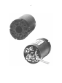
1. DESCRIPTION
The ORTEC 276 Photomultiplier Base is designed
to provide a near-optimum voltage distribution for
essentially all 10-stage photomultiplier tubes that fit
the standard 14-pin tube socket. The unit has a self
contained low-noise integrating preamplifier that
provides gain and line drive capability for the output
signal from the last dynode. The preamplifier is dccoupled to simplify pole-zero cancellation in the
main amplifier. The anode signal is capacitively
coupled to an output BNC connector for use in
coincidence timing or linear pulse-height analysis.
A TEST input is provided to allow pulser calibration
and testing. A FOCUS control on the rear panel is
for optimizing the photocathode first-dynode
electrical field. Some of the photomultiplier tubes
with which this PM base is compatible are:
RCA: 4518, 5819, 6217, 6342A, 6655A, 7326,
8053, 8054, and 8055
Philips: XP-1000 to 1005 and XP-1031 through
1033
EMI: 9536, 9578, 9579, and 9708 Series
CBS: 7817, 7818, 7819, and CL-1004 to 1012
Dumont: 6292, 6363, and 6364
The unit is also compatible with other 10-stage
tubes not listed above. Compatibility can be
determined by comparison with those listed.
2. SPECIFICATIONS
2.1. PHOTOMULTIPLIER TUBE BASE
2.1.1. PERFORMANCE
Design Resistor divider bleeder connected to
14-pin standard PM tube base for 10-stage tubes.
Total resistance 1.49 M, with bleeder current of
1.33 mA when maximum high voltage of 2000 V is
applied.
Voltage Distribution Coefficient Linear to all
stages with focus adjustment on the grid.
2.1.2. CONTROL
FOCUS Single-turn locking potentiometer on panel
for external adjustment of PM tube grid potential.
LAST ANODE Connected internally to preamplifier
input.
2.2. PREAMPLIFIER
2.2.1. PERFORMANCE
Input Directly from last dynode of photomultiplier
tube.
Conversion Gain Nominally 5 µV/eV using a
2 × 2-in. Nal(TI) crystal and a photomultiplier tube
gain of 106.
Rise Time <100 ns for a fast rise time test pulse.
Fall Time Constant 50 µs.
2.1.3. INPUT
HIGH VOLTAGE Type SHV connector on panel
accepts operating voltage for distribution to PM
tube; +2000 V maximum.
2.1.4. OUTPUTS
ANODE Type BNC connector on panel furnishes
PM tube anode negative output pulse for use
primarily as a timing signal; Zo = 1 k ac-coupled.
Integral Nonlinearity <±0.02%, 0 to +10 V.
Output Polarity Positive.
Output Noise <50 µV rms.
Saturation Level
into 93 load.
+10 V into open circuit; +5 V
Gain Temperature Coefficient
0 to 50(C.
<±0.005%/(C,
2
2.2.2. OUTPUT
PREAMP Type BNC connector on panel furnishes
preamplifier positive output pulse for use primarily
as an energy analysis signal. Zo = 93 dccoupled.
Power Requirements
Preamplifier +24 V, 16 mA; 24 V, 16 mA.
2.2.3. INPUTS
Power Cable 3-m (10-ft) captive cable terminates
in Amphenol 17-20090 connector to accept
operating power for the preamplifier circuits.
Compatible with all ORTEC main amplifiers and
with an ORTEC 114 Preamplifier Power Supply.
Weight
Net 0.65 kg (1.5 lb).
Shipping 1.3 kg (3.0 lb).
TEST Type BNC connector on panel accepts test
pulses from an ORTEC Pulse Generator for testing
and calibration. Nominal 100- charge termination
built into preamplifier circuit.
2.3. ELECTRICAL AND MECHANICAL
PM Tube Base +2000 V maximum (use rate
voltage for the PM tube that is installed).
Dimensions 5.58 cm (2.2 in.) diam × 10.1 cm
(4.0 in.) long plus 3-m (10ft) captive power cable.
3. INSTALLATION
3.1. DETECTOR MOUNTING
Normally with 10-stage photomultipliers the amount
of signal current through the tube is small;
therefore, it is quite practical to run positive high
voltage on the tube with the cathode at ground
potential. This means that when the detector is
mounted to the photocathode, very little attention
need be paid to the probability of leakage currents
being created across the glass envelope, since the
voltage potential should be zero. In many cases
where this PM base is used, the detector is
mounted to the photomultiplier in an integral
package.
When a scintillator is mounted on a photomultiplier,
the combination must be made light-tight to ensure
low noise and to eliminate the possibility of
photomultiplier damage. The most common
practice to make the detector/photomultiplier lighttight is to carefully wrap it with a good-quality black
electrical tape. Another is to use an aluminum can
cover and to tape it a the entrance.
3.2. SYSTEM CONNECTION
If it is desired to test and calibrate the system,
connect a pulser to the test input. A 1-V test pulse
should yield a 1-V pulse on the preamplifier output.
The test input is internally terminated in 93 .
Connect a high voltage power supply to the high
voltage input connector and ensure positive
polarity of the high voltage supply. Connect the
preamplifier signal to the energy analysis system
and connect the anode signal to either a timing or
energy analysis system. Use high-quality coaxial
cable and terminate the anode signal cable in its
characteristic cable impedance.
3.3. INITIAL ADJUSTMENTS
The only adjustment on the PM Base is the FOCUS
control, which optimizes the photocathode/firstdynode electrical field.
1. Plug a photomultiplier detector into the unit and
ensure it is light-tight. Connect the positive high
voltage supply.
2. Place a radiation source in the vicinity of the
scintillation detector.
3. Observe the preamplifier output on a sensitive
range of an oscilloscope and slowly increase
the high voltage.
4. If there is a very large amount of unipolar grass
(circuit noise), there is possibly a light leak.
Cover the PM tube with a black cloth to see
whether the grass diminishes; if it does, the
photomultiplier was seeing the ambient light and
should be rechecked for proper covering to
eliminate the light leak.
5. With the high voltage at the desired level,
observe the pulses which are radiation-induced
scintillations and adjust the FOCUS control to
obtain maximum pulse amplitude. This is the
proper setting; lock the adjustment with the
potentiometer lock nut.
3
4. OPERATION
Once the steps outlined in Section 3 of this manual
are performed, the unit is ready for use. High
voltage may be applied and adjusted for the
appropriate gain associated with the specific
experiment. The gain will vary by a factor of
approximately 2 for each high-voltage change of
100 V. NOTE: It is advisable to operate the high
voltage at the minimum practical value when the
high count rates are to be experienced, since count
rate tolerance is a direct function of the
photomultiplier gain.
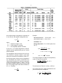
4.1. CALCULATION OF RESPONSE OF
SCINTILLATOR/PHOTOMULTIPLIER
Table 4.1 lists the decay constants of some of the
more common scintillators. The first three
scintillators are crystals. Naton-136, Pilot B, and
NE-102 are plastics, and the last two are liquid
scintillators. The decay time 21 is responsible for a
finite rise time on the leading edge of L(t) (refs. 12,
21, 22); 22 is the fast decay component which is mot
noticeable at the output of the photomultiplier; 23
and 24 are the slow components (important for n-
discrimination with NE-213, NE-218, and Stilbene).
Where measured values were not given, the letters
N.G. have been entered. The parameter P is the
number of photo electrons released at the
photocathode per unit energy. This figure is
affected by the efficiency and spectral response of
the photocathode (refs. 22, 23, 26, 27) and hence
is somewhat characteristic of the photomultiplier
used. However, it provides a reasonably good
guide for comparing the light output of scintillators.
In Table 4.1, P is listed as a fraction of the value for
anthracene; P(anthracene) is ~700 eV/ photoelectron for
S-11 photocathode material.
The thickness of the scintillator is frequently chosen
according to the required stopping power. The flight
time of the radiation (gamma rays or neutrons)
across the scintillator normally becomes a limitation
on the time resolution as the thickness is increased.
Usually detection efficiency must be compromised
for good time resolution.
The scintillator geometry and the coupling to the
phototube must be carefully considered: If the light
can travel a variety of path lengths before being
collected, an additional contribution to the time
resolution will result. Light collection is widely
discussed in the literature (refs. 15, 17–19, 28, 29).
Table 4.2 lists the characteristics of several types of
photomultipliers. It is noteworthy to observe that the
gain of theses tubes ranges from ~0.5 × 10⁶ to 2.5
× 106. This gain is strongly affected by the age of
the tube and the temperature and will change by a
factor of ~2 for each 100-V change in high voltage.
For response calculations there are several
approximations that will aid in a quick “ballpark”
answer:
1. Conversion for absorbed energy (eV) to
photons (p) for anthracene is ~70 eV/p (ref. 35).
2. Conversion of photons to photoelectrons for
S-11 photocathode material is ~10% (ref. 37).
3. 100% of photons are collected on the
photocathode and 100% of cathode-emitted
photoelectrons are collected on the first dynode.
The function for the total charge output now
becomes
Qo E
P
× G × q (coulombs)
× Pceff ×
70
Pa
(1)
where
= output charge in coulombs
Qo
E
= absorbed energy in detector in eV
P/Pa = detector efficiency compared to
anthracene from Table 4.1
G
= photomultiplier gain from Table 4.2 or
from manufacturer’s data
q
= charge per electron 1.6 × 10⁻¹⁹
coulomb
Pceff = efficiency of photocathode or ~10% for
S-11.
4
If the output charge is integrated on a capacitor as
it is on this unit, the capacitor voltage becomes:
Vc Qo
Ci
Example:
Photomultiplier:
RCA-8055,
photocathode, gain 1 × 10⁵ at 1.5 kV.
(2)
Scintillator: Nal.
where
Vc = capacitor voltage in volts
Qo = output charge in coulombs
Ci = the integrating capacitor in farads
Energy Deposited:
Eq. (1)
Qo In this unit, Vc is normally integrated on a 550-pF
capacitor and is amplified with a gain of 5 by the
internal amplifier.
The preamplifier output rise time will be ~80 ns or
2.22, whichever is greater, where 2 is the major
decay time constant of the scintillator (Table 4.1).
If the charge output is driven into a low impedance
as a transmission line which is terminated in its
characteristic impedance (Zo), then the output peak
current will be approximately Io = Qo/2Zo. The rise
time will be limited to about 20–50 ns by the PM
tube. The voltage output under these conditions is
IoZo = Vo; Therefore:
Vo x
Qo
2Zo
S-11
(3)
60
Co 1.33 MeV peak; from
1.33 × 106 eV
× 10%
70
× 2.4 × 1 × 106 × 1.6 ×1019
or
Qo 0.7 × 10¹⁰ coulomb.
This charge integrated on 500 pF and amplified by
a gain of 5 as in this unit will be:
0.7 × 10¹⁰ coulomb
500 × 1012 F
× 5 0.7 V
The rise time from Table 4.1 is 2.2 22, or 550 ns.
The anode pulse into a 50- terminated line will
yield a current pulse of amplitude,
Io Qo
2
10
0.7 × 10 coulomb
9
250 × 10 s
5
or
Io or
Qo
T
0.7 × 10¹⁰ coulomb
250 × 109 S
Io 0.28 mA
and again the rise time will be ~20–50 ns, and the
output voltage peak will be IoRo or Vout =
0.28 mA × 50 = 14 mV.
4.2. TIMING APPLICATIONS
The different specific applications for the unit are
essentially limitless, but since it is designed for
timing as well as spectroscopy, two of the most
often used coincidence systems are discussed and
block diagrams given. From these two block
diagrams other applications may be formulated by
extension.
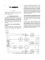
4.2.1. TYPICAL FAST-SLOW COINCIDENCE
SYSTEM
The block diagram of Fig. 4.1 outlines a fast-slow
coincidence system. The words “fast-slow” mean
that there are essentially two channels of
information retrieval operating in parallel. The fast
channel sets the ultimate resolving time of the
coincidence circuitry, while the slow channel
selects the pulse height range to be accepted from
each detector and by means of a slower
coincidence requirement combines this with the fast
coincidence requirement to yield information having
the criteria of the fast resolving time of the fast
channel and the energy selection of the slow
channel simultaneously.
In the fast channel the timing amplifiers indicated
may be the ORTEC 474 or equivalent or may be a
combination of fast amplifier/fast discriminator such
as the ORTEC 260 Time Pickoff Unit with the 402A
Time Pickoff Control to extract fast timing
information.
As shown in Fig. 4.1, the time spectrum from the
time to amplitude converter is analyzed as the
information channel. Of course, the output of the
time-to-amplitude converter could be fed to the
single channel analyzer to form an alternate fast
coincidence channel, which could then feed the
coincidence circuit and allow pulse height analysis
of either detector channel as desired.
Fig. 4.1. Typical Fast-Slow Coincidence System Using Scintillators.
6
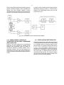
Figure 4.2 outlines a simple conventional crossover
pick-off coincidence system, which is probably the
easiest and most versatile method of doing
coincidence when the ultimate resolving time is not
required. This method is very easy to use; however,
it results in a 22 coincidence resolving time which is
theoretically worse by a factor of ~12 than may be
achieved by leading-edge timing such as was
indicated in Fig. 4.1.
Fig. 4.2. Conventional Crossover Pickoff Coincidence System.
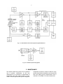
4.2.2. GAMMA-GAMMA COINCIDENCE
SYSTEM FOR THE HIGH-PURITY GERMANIUM
(HPGe) DETECTOR
Figure 4.3 is a block diagram of an experimental
setup that is quite versatile for studying decay
schemes and transitional levels by means of
coincidence between an HPGe detector and a
scintillation detector. With this block diagram the
experimenter may study either energy information
or time information associated with the coincidence
events.
4.3. SCINTILLATION SPECTROSCOPY
Scintillation spectroscopy implies the measurement
of energy by the direct conversion of energy to light
in a scintillator and the detection thereof by the
photomultiplier. The system to perform this function
is one of the most simple, requiring only the
phosphor, the photomultiplier, a base structure for
the PM tube, a preamplifier, and a linear amplifier
with some type of measuring device such as a
multichannel analyzer (Fig. 4.4). With this system
one may study directly the energy released in the
phosphor by some incident radiation.
7
Fig. 4.3. Gamma-Gamma Coincidence System Using HPGe Detectors.
Fig. 4.4. Scintillation Spectrometry System.
5. MAINTENANCE
The resistor divider string of this unit is composed
only of passive components; so the only
maintenance to be expected is replacement of
components that have failed because of age.
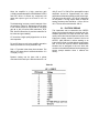
Table 5.1 lists the approximate dynode voltages for
comparative purposes. Almost all failures of the
dynode string may be isolated by removing the PM
tube and making these measurements. Use a
voltmeter of >20,000 /V for this measurement.
8
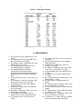
Since the amplifier is a high, open-loop gain
(~6000) operational amplifier with feedback via R23
and R24, failure of almost any component will
cause the output to go to a dc level of ~±5 V to
±24 V.
Troubleshooting involves a careful analysis of the
dc levels from Table 5.2. Replacement of the parts
is not critical except Q1–Q4 should be very high
gain ( or hfe) low-noise NPN transistors. R19,
R23, and R24 should be of precision metal film for
low noise and good stability.
C7 should be a high quality dipped mica or silver
mica capacitor.
D1 and D2 have no role in the amplifier operation
and are provided for circuit protection only.
R19 × C7 product is the decay time constant. The
90% to 10% decay time in seconds should be ~2.2
× R19() × C7(F).
100 pF and C7 of 500 pF the preamplifier output
amplitude should be approximately the same
amplitude and the same polarity as the pulser input.
The decay time should be ~50–150 µs, depending
on the pulser. If a long square wave is used for
testing, the decay time should be ~110 µs, 90% to
10%. The rise time should be 80–100 ns.
5.1. FACTORY REPAIR
This instrument can be returned to the ORTEC
factory for service and repair at a nominal cost. Our
standard procedure for repair ensures the same
quality control and checkout that are used to a new
instrument. Always contact Customer Service at
ORTEC, (865) 482-4411, before sending in an
instrument for repair to obtain shipping instructions
and so that the required Return Authorization
Number can be assigned to the unit. Write this
number on the address label and on the package to
ensure prompt attention when it reaches the
factory.
Dynamic testing can be done with a pulser
connected to the test input. With the normal Ctest of
Table 5.1
9
Table 5.2. Preamplifier Voltages.
6. BIBLIOGRAPHY
1. P.R. Orman, Nucl. Instr. Methods 21(1), 121
(1963).
2. D.L. Wieber and H.W. Lefevre, IEEE Trans.
Nucl. Sci. NS-13(1), 406 (1966).
3. D.A. Gedcke and W. J. McDonald, Nucl. Instr.
Methods 55(2), 377 (1967).
4. D. A. Gedcke and W. J. McDonald, Nucl.
Instr. Methods 58(2), 253 (1968).
5. W.J. McDonald and D.A. Gedcke,
“Electronics for Fast Neutron Work,”
presented at the International Symposium on
Nuclear Electronics, Versailles, September
1968.
6. R. Nutt, IEEE Trans. Nucl. Sci. NS-14(1), 110
(1967).
7. P.D. Compton, Jr., and W.A. Johnson, IEEE
Trans. Nucl. Sci. NS-14(1) 116 (1967).
8. M. Bertolaccini et al., Nucl. Instr. Methods
51(2), 325 (1967).
9. E. Gatti and V. Svelto, Nucl. Instr. Methods
43(1), 248 (1966).
10. S. Donati, E. Gatti, and V. Svelto, Nucl. Instr.
Methods 46(1), 165 (1967).
11. L.G. Hyman, R.M. Schwarcz, and R.A.
Schluter, Rev. Sci. Instr. 35(3), 393 (1964).
12. L.G. Hyman, Rev. Sci. Instr. 36(2), 193
(1965).
13. C.R. Kerns, IEEE Trans. Nucl. Sci. NS-14(1),
449 (1967).
14. M. Cocchi and A Rota, Nucl. Instr. Methods
55(2), 365 (1967).
15. G. Bertolini et al., IEEE Trans. Nucl. Sci.
NS-13(3), 119 (1966).
16. J.A. Miehe, E. Ostertag, and A. Coche, IEEE
Trans. Nucl. Sci. NS-13(3), 127 (1966).
17. A. Schwarzchhild, Nucl. Instr. Methods 21(1),
1 (1963).
18. G. Present et al., Nucl. Instr. Methods 31(1),
71 (1964).
19. W. J. McDonald and D.A. Gedcke, Nucl. Instr.
Methods 55(1), 1 (1967).
20. R.E. Bell, Nucl. Instr. Methods 43(2), 211
(1966).
21. R.L. McGuire and R.C. Palmer, IEEE Trans.
Nucl. Sci. NS-14(1), 217 (1967).
22. F.J. Lynch IEEE Trans Nucl. Sci. NS-15(3), 102
(1968).
23. F.T. Kuchnir and F.J. Lynch, IEEE Trans. Nucl.
Sci. NS-15(3), 107 (1968).
24. W.R. Wall and K. I. Roulston, IEEE Trans.
Nucl. Sci. NS-15(3), 153 (1968).
25. J. Kirkbride, E. C. Yates, and D.G. Crandall,
Nucl. Instr. Methods 52(2), 293 (1967).
10
26. F. J. Lynch, IEEE Trans. Nucl. Sci. NS-13(3),
140 (1966).
27. A. Houdayer, S.K. Mark, and R.E. Bell, Nucl.
Instr. Methods 59(2), 319 (1968).
28. E. Rosenstingl et al., Nucl. Inst. Methods 58(1),
61 (1968).
29. P.K.F. Greider, Nucl. Instr. Methods 55(2), 295
(1967).
30. J. Braunsfurth and H.J. Körner, Nucl. Instr.
Methods 34(2), 202 (1965).
31. M.L. Rousch, M.A. Wilson, and W.F. Hornyak,
Nucl. Instr. Methods 31(1), 112 (1964), and
references contained therein.
32. D. Landis and F.S. Goudling, Nat. Acad. Sci. –
Nat. Res. Council Publ. 1184, 143 (1963).
33. W. J. McDonald and D. A. Gedcke, “Detection
34.
35.
36.
37.
System for a Fast Neutron Time-of-Flight
Spectrometer,” Nuclear Research Center
Report, Physics Department, University of
Alberta, Edmonton, Alberta, Canada (1967)
(copies available from the authors).
W.J. Price, Nuclear Radiation Detection, 2d ed,
McGraw-Hill, New York, 1964.
Yu K. Akimov, “Scintillation Counters in High
Energy Physics,” Adademic Press, New York,
1965.
D. Gedcke and C.W. Williams, “High
Resolution Time Spectroscopy. 1. Scintillation
Detectors,” ORTEC Publication August 1968.
RCA Photocathode Spectral Response
Characteristics Chart P IT-701B.
![[U2.03.04] Notice d`utilisation pour des calculs](http://vs1.manualzilla.com/store/data/006355171_1-e4204e3f6eed19ac00fe22b1d72a0ea8-150x150.png)

![[U4.81.22] Opérateur POST_ELEM](http://vs1.manualzilla.com/store/data/006355219_1-23fca5f34f44a4b1ae5a58e21cb48848-150x150.png)