1
Model 265A
Photomultiplier Base
Operating and Service Manual
Printed in U.S.A.
ORTEC® Part No. 733110
Manual Revision C
0905
$GYDQFHG0HDVXUHPHQW7HFKQRORJ\,QF
a/k/a/ ORTEC®, a subsidiary of AMETEK®, Inc.
WARRANTY
ORTEC* warrants that the items will be delivered free from defects in material or workmanship. ORTEC makes
no other warranties, express or implied, and specifically NO WARRANTY OF MERCHANTABILITY OR
FITNESS FOR A PARTICULAR PURPOSE.
ORTEC’s exclusive liability is limited to repairing or replacing at ORTEC’s option, items found by ORTEC to be
defective in workmanship or materials within one year from the date of delivery. ORTEC’s liability on any claim
of any kind, including negligence, loss, or damages arising out of, connected with, or from the performance or
breach thereof, or from the manufacture, sale, delivery, resale, repair, or use of any item or services covered
by this agreement or purchase order, shall in no case exceed the price allocable to the item or service furnished
or any part thereof that gives rise to the claim. In the event ORTEC fails to manufacture or deliver items called
for in this agreement or purchase order, ORTEC’s exclusive liability and buyer’s exclusive remedy shall be
release of the buyer from the obligation to pay the purchase price. In no event shall ORTEC be liable for special
or consequential damages.
Quality Control
Before being approved for shipment, each ORTEC instrument must pass a stringent set of quality control tests
designed to expose any flaws in materials or workmanship. Permanent records of these tests are maintained
for use in warranty repair and as a source of statistical information for design improvements.
Repair Service
If it becomes necessary to return this instrument for repair, it is essential that Customer Services be contacted
in advance of its return so that a Return Authorization Number can be assigned to the unit. Also, ORTEC must
be informed, either in writing, by telephone [(865) 482-4411] or by facsimile transmission [(865) 483-2133], of
the nature of the fault of the instrument being returned and of the model, serial, and revision ("Rev" on rear
panel) numbers. Failure to do so may cause unnecessary delays in getting the unit repaired. The ORTEC
standard procedure requires that instruments returned for repair pass the same quality control tests that are
used for new-production instruments. Instruments that are returned should be packed so that they will withstand
normal transit handling and must be shipped PREPAID via Air Parcel Post or United Parcel Service to the
designated ORTEC repair center. The address label and the package should include the Return Authorization
Number assigned. Instruments being returned that are damaged in transit due to inadequate packing will be
repaired at the sender's expense, and it will be the sender's responsibility to make claim with the shipper.
Instruments not in warranty should follow the same procedure and ORTEC will provide a quotation.
Damage in Transit
Shipments should be examined immediately upon receipt for evidence of external or concealed damage. The
carrier making delivery should be notified immediately of any such damage, since the carrier is normally liable
for damage in shipment. Packing materials, waybills, and other such documentation should be preserved in
order to establish claims. After such notification to the carrier, please notify ORTEC of the circumstances so
that assistance can be provided in making damage claims and in providing replacement equipment, if
necessary.
Copyright © 2005, Advanced Measurement Technology, Inc. All rights reserved.
*ORTEC® is a registered trademark of Advanced Measurement Technology, Inc. All other trademarks used herein are
the property of their respective owners.
iii
CONTENTS
SAFETY INSTRUCTIONS AND SYMBOLS . . . . . . . . . . . . . . . . . . . . . . . . . . . . . . . . . . . . . . . . . . . . . . . . . . iv
SAFETY WARNINGS AND CLEANING INSTRUCTIONS . . . . . . . . . . . . . . . . . . . . . . . . . . . . . . . . . . . . . . . v
1. DESCRIPTION . . . . . . . . . . . . . . . . . . . . . . . . . . . . . . . . . . . . . . . . . . . . . . . . . . . . . . . . . . . . . . . . . . . . . . 1
2. SPECIFICATIONS . . . . . . . . . . . . . . . . . . . . . . . . . . . . . . . . . . . . . . . . . . . . . . . . . . . . . . . . . . . . . . . . . . .
2.1. PERFORMANCE . . . . . . . . . . . . . . . . . . . . . . . . . . . . . . . . . . . . . . . . . . . . . . . . . . . . . . . . . . . . . . . .
2.2. CONTROLS . . . . . . . . . . . . . . . . . . . . . . . . . . . . . . . . . . . . . . . . . . . . . . . . . . . . . . . . . . . . . . . . . . . .
2.3. INPUTS . . . . . . . . . . . . . . . . . . . . . . . . . . . . . . . . . . . . . . . . . . . . . . . . . . . . . . . . . . . . . . . . . . . . . . .
2.4. OUTPUTS . . . . . . . . . . . . . . . . . . . . . . . . . . . . . . . . . . . . . . . . . . . . . . . . . . . . . . . . . . . . . . . . . . . . .
2.5. RELATED EQUIPMENT . . . . . . . . . . . . . . . . . . . . . . . . . . . . . . . . . . . . . . . . . . . . . . . . . . . . . . . . . .
2.6. MECHANICAL DATA . . . . . . . . . . . . . . . . . . . . . . . . . . . . . . . . . . . . . . . . . . . . . . . . . . . . . . . . . . . . .
1
1
1
1
1
2
2
3. INSTALLATION . . . . . . . . . . . . . . . . . . . . . . . . . . . . . . . . . . . . . . . . . . . . . . . . . . . . . . . . . . . . . . . . . . . . .
3.1. DETECTOR MOUNTING . . . . . . . . . . . . . . . . . . . . . . . . . . . . . . . . . . . . . . . . . . . . . . . . . . . . . . . . . .
3.2. PHOTOMULTIPLIER INSERTION . . . . . . . . . . . . . . . . . . . . . . . . . . . . . . . . . . . . . . . . . . . . . . . . . .
3.3. INITIAL ADJUSTMENTS . . . . . . . . . . . . . . . . . . . . . . . . . . . . . . . . . . . . . . . . . . . . . . . . . . . . . . . . . .
3.4. CONNECTION INTO A SYSTEM . . . . . . . . . . . . . . . . . . . . . . . . . . . . . . . . . . . . . . . . . . . . . . . . . . .
2
2
2
2
3
4. OPERATION . . . . . . . . . . . . . . . . . . . . . . . . . . . . . . . . . . . . . . . . . . . . . . . . . . . . . . . . . . . . . . . . . . . . . . . . 4
4.1. TIMING WITH PHOTOMULTIPLIERS . . . . . . . . . . . . . . . . . . . . . . . . . . . . . . . . . . . . . . . . . . . . . . . . 4
4.2. APPLICATIONS . . . . . . . . . . . . . . . . . . . . . . . . . . . . . . . . . . . . . . . . . . . . . . . . . . . . . . . . . . . . . . . . . 4
5. CIRCUIT DESCRIPTION . . . . . . . . . . . . . . . . . . . . . . . . . . . . . . . . . . . . . . . . . . . . . . . . . . . . . . . . . . . . . 10
iv
SAFETY INSTRUCTIONS AND SYMBOLS
This manual contains up to three levels of safety instructions that must be observed in order to avoid
personal injury and/or damage to equipment or other property. These are:
DANGER
Indicates a hazard that could result in death or serious bodily harm if the safety instruction
is not observed.
WARNING
Indicates a hazard that could result in bodily harm if the safety instruction is not observed.
CAUTION
Indicates a hazard that could result in property damage if the safety instruction is not
observed.
Please read all safety instructions carefully and make sure you understand them fully before attempting to
use this product.
In addition, the following symbol may appear on the product:
ATTENTION–Refer to Manual
DANGER–High Voltage
Please read all safety instructions carefully and make sure you understand them fully before attempting to
use this product.
v
SAFETY WARNINGS AND CLEANING INSTRUCTIONS
DANGER
Opening the cover of this instrument is likely to expose dangerous voltages. Disconnect the
instrument from all voltage sources while it is being opened.
WARNING Using this instrument in a manner not specified by the manufacturer may impair the
protection provided by the instrument.
Cleaning Instructions
To clean the instrument exterior:
Unplug the instrument from the ac power supply.
Remove loose dust on the outside of the instrument with a lint-free cloth.
Remove remaining dirt with a lint-free cloth dampened in a general-purpose detergent and water
solution. Do not use abrasive cleaners.
CAUTION To prevent moisture inside of the instrument during external cleaning, use only enough liquid
to dampen the cloth or applicator.
Allow the instrument to dry completely before reconnecting it to the power source.
vi
1
ORTEC MODEL 265A
PHOTOMULTIPLIER BASE
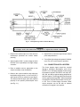
1. DESCRIPTION
The ORTEC 265A Photomultiplier Base structure
provides a mechanical assembly and resistive
voltage divider network, with appropriate capacity
decoupling, for operation of the Burle 8850 or
Hamamatsu R1332 photomultiplier. This tube is a
bi-alkali photocathode device with very good timing
and energy resolution characteristics. The tube is
capable of relatively high pulse currents when used
in timing applications, and this base structure
complements the tube characteristics by
maintaining good pulse fidelity over a wide range of
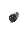
signal currents (see Fig. 1.1). The unit provides two
outputs: the negative anode signal for timing
applications and the linear signal from the ninth
dynode. This linear signal is of special importance
in any experiment in which energy measurements
are desired.
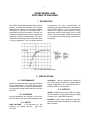
Fig. 1.1. Typical Anode Output Pulse.
2. SPECIFICATIONS
2.1. PERFORMANCE
All photomultiplier tube specifications are furnished
by the manufacturer. The 265A Base accommodates the RCA-8575 or -8850 tube and includes
an appropriate voltage divider network for the tube
elements.
2.2. CONTROLS
Internal adjustments are included for the focus
electrode and for the second and twelfth dynodes.
2.3. INPUTS
HIGH VOLTAGE
-3 kV maximum at 2 mA
maximum for bleeder network.
Type SHV
connector.
AUXILIARY Last four dynodes are available at
pins in the Auxiliary connector for optional external
voltage stabilization; type MS3112E12-10S or
Bendix PT02E-12-10S connector.
2.4. OUTPUTS
ANODE Negative timing signal, 50 dc-coupled,
back-terminated; very good pulse quality for signal
currents to 0.5 A; type BNC connector.
DYNODE Positive linear signal from 9th dynode,
capacity coupled, high impedance (Zo 1 M); type
BNC connector.
2
2.5. RELATED EQUIPMENT
2.6. MECHANICAL DATA
The Anode timing signal can be furnished to a fast
discriminator such as the ORTEC 453 or 436 when
using either a NaI(TI) or plastic scintillator. For
plastic scintillators only, the Anode signal can be
fed directly to the Start or Stop input of an ORTEC
437A, 447, or 457 Time to Pulse Height Converter.
The linear output from the 9th dynode is normally
processed through an ORTEC 113 Scintillation
Preamplifier and a shaping amplifier such as the
ORTEC 410, 450, 451, 452, 460, or 485.
WEIGHT (Shipping)
265A PM Base 3 lb (1.37 kg).
218 Shield 2 lb (0.9 kg)
C36-12 Cable <1 lb (<0.46 kg).
WEIGHT (Net)
265A PM Base 1.4 lb (0.63 kg).
218 Shield 1 lb (0.46 kg).
C36-12 Cable <1 lb (<0.46 kg).
DIMENSIONS
265A PM Base 3-in. dia. x 8 in. long.
218 Shield 3-in. dia.; assembled 265A and 218
13 in long.
C36-12 Cable 12 ft long.
3. INSTALLATION
3.1. DETECTOR MOUNTING
The ORTEC 265A is designed for the best in pulse
fidelity and requires that the anode be operated at
ground potential. This means that the photocathode
is at negative HV. Assure that this high voltage is
not dropped across the glass envelope of the
photomultiplier. Be careful to prevent the scintillator
from imposing a ground at the front surface of the
photocathode. A drawing of the suggested method
of mounting a simple detector is shown in Fig. 3.1.
(Scotch Type 33 is recommended for the two layers
of electrical tape shown in Fig. 3.1 that are to be
applied over the photomultiplier tube. This product
not only affords the necessary electrical insulation
but also minimizes noise that would be present
because of extraneous light that could reach the
tube structure. This tape wrapping should be
extended beyond the physical body of the
photomultiplier tube to include the tapered surface
of the tube socket within the light-shielded
configuration.)
3.2. PHOTOMULTIPLIER INSERTION
Remove the magnetic shield, if used. The tube may
now be inserted directly into the light-tight socket.
Place the felt washers around the photomultiplier
and remount the magnetic shield.
3.3. INITIAL ADJUSTMENTS
Remove the high voltage divider cover. The
controls of the unit are trimmed for optimum
operation with a specific PM at the factory.
However, the unit will probably need trimming again
when a different PM is used. These adjustments
need to be performed rarely more than once with a
specific PM unless the operating HV is varied more
than ±200 V.
3
Fig. 3.1. Cutaway Drawing of PM - Scintillator Mounting.
WARNING
The voltages used in this network are dangerous so adjust the controls cautiously.
1. Observe the Anode output on a fast rise time
oscilloscope (terminate the coaxial cables
properly).
2. Apply negative 2200 V (or the voltage at which
the tube is to be operated) to the high voltage
connector.
3. Place a radiation source, appropriate to the
chosen scintillator, near the detector.
4. Observe the output waveform and adjust the
two bleeder string controls, i.e., the Focus (R17)
and Dynode (R15) for maximum output signal.
This assures that the input optics are adjusted
properly for the specific photomultiplier used
(see Fig. 3.1).
5. Adjust R26 for maximum signal output without
pulse shape distortion.
6. Turn off the high voltage and replace HV divider
cover The unit is now ready for operation.
3.4. CONNECTION INTO A SYSTEM
The linear dynode signal should be coupled
through a scintillation preamplifier, such as the
ORTEC 113, to a shaping amplifier if linear energy
information is desired. The ORTEC 410, 450, 451,
452, 460, and 485 are typical shaping amplifiers for
the linear signals. The timing signal from the anode
can be connected through 50 cable (terminated)
to an ORTEC 436 Fast Discriminator or 437A, 447,
or 457 Time to Pulse Height Converter. Either
output connector can be left with no external
connection if its signal is not required.
4
4. OPERATION
Once the steps outlined in Section 3 of this manual
have been performed the unit is ready for use.
Negative high voltage may be applied and adjusted
for the appropriate gain associated with the specific
experiment. The gain will vary by a factor of
approximately 2 with a high voltage change of
100 V.
4.1. TIMING WITH PHOTOMULTIPLIERS
Timing with photomultipliers implies some type of
coincidence measurement. This measurement may
be performed with standard coincidence circuits
such as the pulse overlap type, which are
essentially single channel time analyzers, or with
time to pulse height converters, which are
differential type, or with multichannel analyzers.
The response of the coincidence system to a
prompt cascade always has finite width which
comes from a variety of sources. The most
important of these are as follows:
1. Variation of time of interaction of radiation with
the scintillator and the amount of energy
deposited therein,
2. Finite decay time of light-emitting states in the
phosphor and variation of times of photon
arrival at the multiplier cathode,
3. Variation of transit time of photoelectrons in the
photomultiplier due to different path lengths and
to variation of initial energy and angle of the
secondary electrons,
4. Jitter and uncertainties of triggering times of the
associated electronics.
The variation of the time of interaction can be
minimized by appropriate geometry and small
scintillators at a corresponding loss in efficiency
and average energy deposition.
For a complete discussion of timing with
photomultipliers, the reader is referred to some of
the excellent literature available on the subject.1-5
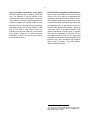
4.2. APPLICATIONS
The different specific applications for the ORTEC
265A are essentially limitless, but since the unit
was designed primarily for timing applications, a
number of system block diagrams utilizing this unit
are given. Some typical resolution curves for three
of the systems are given separately, from which
operational characteristics of other systems may be
implied.
Typical Fast-Slow Coincidence System Using
Plastic Scintillators Figure 4.1 is a block diagram
of a system that might be used to perform lifetime
measurements or to study the time dispersion
associated with some prescribed coincidence
events. It does not represent an optimum system if
clean slopes of the coincidence curves are required
to four or five decades, but will give clean spectra
to at least three decades at moderately high count
rates. The time spectrum shown in Fig. 4.2
represents what may be obtained under laboratory
conditions using the ORTEC 265A and other
appropriate equipment. It is important to remember
that the resolution obtainable varies as 1n. where
n represents the number of photoelectrons created
by the event and is therefore representative of the
amount of energy deposited in the scintillating
phosphor and is strongly influenced by PM optics.
1
A. Schwarmhild, "A Survey of the Latest Developments in
Delayed Coincidence Measurements," Nuct. lnstr. Methods
21 (1), 1 (1963).
2
G. Present et al., "Fast Delayed Coincidence Technique: The
XPI020 Photomultiplier and Limits of Resolving Times Due to
Scintillator Characteristics," Nucl. lnstr. Methods 31(l), 71
(1964).
3
E. Gatti and V. Svelto, "Revised Theory of Time Resolution in
Scintillation Counters," Nuct. Instr. Methods 30, 213 (1964).
4
D.A. Godcke and C.W. Williams, High Resolution Time
Spectroscopy. 1. Scintillation Detectors, ORTEC
publication, August 1968.
5
"Timing with Ge(Li) Detectors," ORTEC Application Note 31,
1970.
5
Typical Fast-Slow Coincidence Using Nal(TI)
The block diagram of Fig. 4.1 applies equally well
here. The difference in the two systems is the.
scintillator and its decay characteristic. This decay
time constant is 0.25 µsec, whereas the same time
constant for Naton-136 is approximately 2 nsec.
With NaI(TI) much more total light is produced per
equivalent energy event, but the collection of this
light is over such a wide period of time, as
indicated, that the time resolution is poorer than
that of plastic. Figure 4.3 is a typical spectrum
taken with a 1½-in. by 1-in. NaI (TI) on one side of
the coincidence system.
Fast Coincidence Using Ge(Li-Drifted) Detectors
Some recent experiments have been performed
using a 1½-in. by 1-in. NaI(TI) in a gamma-gamma
coincidence arrangement with an ORTEC 10-cm3
Ge(Li-drifted) coaxial detector, as shown in Fig. 4.4.
In this case the radiant energy from the source was
not collimated at all, so that the time is given by
collection from all parts of the detector. The source
viewed one end of a germanium detector. Side
channels selected the energy region of interest,
which was the photopeak on each side. The full
time spectrum is given in Fig. 4.5. Full width at half
maximum and full width at one-tenth maximum are
indicated. This, when compared with published
timing curves6 indicates a very good detector
design for timing purposes.
6
R.L. Graham et al., "Timing Characteristics of Large Coaxial
Ge(Li) Detertors for Coincidence Experiments," IEEE Trans.
Nucl. Sci. NS-13(l), 72 (1966).
6
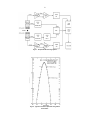
Fig. 4.1. Simple Fast-Slow Timing System.
Fig. 4.2. Typical Coincidence Spectrum Using Plastic
Scintillators.
7
Fig. 4.3. Typical Coincidence Spectrum Using
NaI(Tl) Scintillator.
Fig. 4.5. Timing Spectrum with Ge(Li-Drifted)
Detector.
Fig. 4.4. Gamma-Gamma Coincidence System with a Ge(Li-Drifted) Detctor.
8
System Block Diagrams A number of experimental systems are shown in Figs. 4.6–4.9 for the aid of the user.
Fig. 4.6. Fast-Fast Coincidence (Photomultiplier Tube) with Pulse Shape Discrimination.
Fig. 4.7. Fast Timing System (Semiconductor Detector - Photomultiplier Tube) for Coincidence Using
Crossover Pickoff Techniques.
9
Fig. 4.8. Semiconductor-PM Coincidence Using Conventional Crossover Timing.
Fig. 4.9. Subnanosecond Timing System (Semiconductor - Photomultiplier Tube).
10
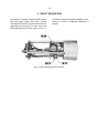
5. CIRCUIT DESCRIPTION
The divider is a “graded” resistance divider whose
gain and signal quality have been carefully
considered. R15 and R17 perform the function of
optimizing the input optics. An open view of the
265A showing these controls is given in Fig. 5.1.
The last four dynodes are directly available at J4 for
external dc control or additional capacitance if
desired.
Fig. 5.1. Open Unit Showing Picture of Controls.