1
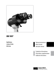
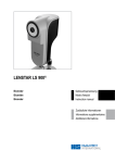
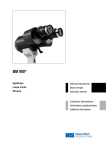
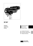
SVENSKA
NEDERLANDS
PORTUGUÊS
ESPAÑOL
ITALIANO
FRANÇAIS
DEUTSCH
ENGLISH
INSTRUCTIONS FOR USE
Biometer
Lenstar LS 900®
8. Edition / 2014 – 11
© HAAG-STREIT AG, 3098 Koeniz, Switzerland – HS-Doc. no. 1500.7220055.04080 – 8. Edition / 2014 – 11
01-IFU_LS900-7220055-04080_eng.indd 1
1
04.11.2014 09:43:43
ENGLISH
DEUTSCH
FRANÇAIS
ITALIANO
ESPAÑOL
INSTRUCTIONS FOR USE
Biometer
Lenstar LS 900
8. Edition / 2014 – 11
Introduction
Thank you for choosing a HAAG‑STREIT device. Provided you comply careful‑
ly with the regulations in these instructions for use, we can guarantee reliable and
trouble-free use of our product.
WARNING!
Read the instruction manual carefully before commissioning this product. It contains important information regarding the safety of the user
and patient.
NOTE!
Federal law restricts this device to sale by or on the order of a physician
or licensed practitioner.
2
The LS 900 is a non-invasive, non-contact OLCR (optical low-coherence reflectom‑
etry) biometer used for obtaining ocular measurements and performing calculations
to assist in the determination of the appropriate power and type of IOL (intraocular
lens) for implantation after removal of the natural crystalline lens. The LS 900 mea‑
sures:
• Axial eye length
• Corneal thickness
• Anterior chamber depth
• Aqueous depth
• Lens thickness
• Corneal curvature
• Radii for flat and steep meridian
• Axis of the flat meridian
• White-to-white distance
• Pupil diameter
01-IFU_LS900-7220055-04080_eng.indd 2
NEDERLANDS
SVENSKA
Contents
®
Intended use
PORTUGUÊS
1.
Safety...................................................................................... 4
2.
Introduction............................................................................ 8
3.
Appliance assembly / installation......................................... 9
4.
Operation.............................................................................. 10
1.1
1.2
1.3
1.4
1.5
1.6
1.6.1
1.6.2
1.6.3
1.6.4
1.6.5
1.6.6
1.7
1.8
1.9
1.10
2.1
2.2
2.3
2.4
3.1
3.2
4.1
4.2
4.3
4.3.1
4.3.2
4.3.3
4.4
4.5
4.5.1
4.5.2
4.5.3
4.5.4
Areas of application of the device..............................................................................4
Patient population......................................................................................................4
Ambient conditions.....................................................................................................4
Shipment and unpacking...........................................................................................4
Installation warnings..................................................................................................4
Operation, environment.............................................................................................4
Plausibility of the measurements...............................................................................5
IOL calculation...........................................................................................................6
References.................................................................................................................6
IOL constants.............................................................................................................6
IOL constants derived using data from an immersion ultrasound biometer...............7
IOL constants derived from data from a contact ultrasound biometer.......................7
Optical radiation.........................................................................................................7
Disinfection................................................................................................................7
Warranty and product liability.....................................................................................7
Symbols.....................................................................................................................7
Basic construction......................................................................................................8
Examination components (LS 900)............................................................................8
Control component (PC)............................................................................................9
Instrument table (option)............................................................................................9
Computer connection.................................................................................................9
Installing a short forehead band when using the
optional T-Cone..........................................................................................................9
Position of patient during measurement..................................................................10
Measuring with LENSTAR APS (optional)................................................................10
Optional T-Cone.......................................................................................................10
Fitting the optional T-Cone.......................................................................................10
Measuring with the optional T-Cone.........................................................................11
Removing the optional T-Cone.................................................................................11
Fixation....................................................................................................................11
Measured variables..................................................................................................11
A-Scan.....................................................................................................................11
Keratometry.............................................................................................................12
White-to-white distance............................................................................................12
Pupillometry & visual axis........................................................................................12
© HAAG‑STREIT AG, 3098 Koeniz, Switzerland – HS-Doc. no. 1500.7220055.04080 – 8. Edition / 2014 – 11
04.11.2014 09:43:43
SVENSKA
NEDERLANDS
5.
Commissioning.................................................................... 12
6.
Technical data...................................................................... 12
5.1
5.2
6.1
6.2
6.2.1
6.2.2
6.3
6.3.1
6.3.2
6.3.3
6.3.4
6.4
6.4.1
6.4.2
6.4.3
6.4.4
6.4.5
6.4.6
6.4.7
6.4.8
6.5
6.5.1
6.5.2
6.5.3
Switching on the device...........................................................................................12
Switching off the device...........................................................................................12
Weight......................................................................................................................12
Power supply...........................................................................................................12
Primary side.............................................................................................................12
Secondary side........................................................................................................12
Illumination modalities..............................................................................................13
Eye length measurement (A-Scan) and central fixation...........................................13
Keratometry.............................................................................................................13
Illumination...............................................................................................................13
Positioning aid (from serial number 2000)...............................................................13
Measured variables Lenstar LS 900........................................................................13
Central corneal thickness (CCT)..............................................................................13
Anterior chamber depth (ACD).................................................................................13
Lens thickness (LT)..................................................................................................13
Axial length (AL).......................................................................................................13
Keratometry (R).......................................................................................................13
White-to-white distance (WTW)...............................................................................13
Pupillometry.............................................................................................................13
Study design............................................................................................................13
Technical data of T-Cone (option)............................................................................14
Normative considerations........................................................................................14
Measuring accuracy ................................................................................................14
Reproducibility.........................................................................................................15
7.
Software / Help menu / Error messages............................ 15
8.
Maintenance......................................................................... 15
8.1
8.2
8.3
ESPAÑOL
PORTUGUÊS
ITALIANO
FRANÇAIS
DEUTSCH
A.
Appendix............................................................................... 16
B.
Legal regulations................................................................. 16
C.
Classification ....................................................................... 16
D.
Disposal................................................................................ 16
E.
Standards.............................................................................. 16
ENGLISH
A.1
Accessories / spare parts.........................................................................................16
A1.1 LENSTAR LS 900....................................................................................................16
A.1.2 T-Cone (option)........................................................................................................16
C.1
C.2
F.
F.1
F.2
F.3
F.4
F.4
LENSTAR LS 900 biometer.....................................................................................16
T-Cone (option)........................................................................................................16
EMC supplement ................................................................. 17
General....................................................................................................................17
Emitted interference (standard table 1)....................................................................17
Immunity (standard table 2).....................................................................................18
Immunity on non-life support devices (standard table 4).........................................19
Safe distances on non-life support devices (standard table 6)................................20
Function check / zero adjustment............................................................................15
Cleaning...................................................................................................................15
Maintenance of T-Cone (option)...............................................................................15
© HAAG‑STREIT AG, 3098 Koeniz, Switzerland – HS-Doc. no. 1500.7220055.04080 – 8. Edition / 2014 – 11
01-IFU_LS900-7220055-04080_eng.indd 3
3
04.11.2014 09:43:43
ENGLISH
1.
DEUTSCH
FRANÇAIS
ITALIANO
ESPAÑOL
Safety
DANGER!
Failure to comply with these instructions may result in material damage
or pose a danger to patients or users.
WARNING!
These warnings must absolutely be complied with to guarantee
safe operation of the device and to avoid any danger to users and
to patients.
PORTUGUÊS
Areas of application of the device
1.2
Patient population
1.3
moving.
• Only use the original packaging material for moving the device.
• Check that the contents of the packaging correspond to the contents specified on the
leaflet included in the packaging.
1.5
Ambient conditions
The patient must be capable of sitting up straight and keeping his head still. He
must be physically and mentally able to cooperate well and mentally capable of fol‑
lowing the examination. Patients must be at least 6 years old.
Storage:
Use:
Temperature
Air pressure
Relative humidity
Temperature
Air pressure
Relative humidity
Temperature
Air pressure
Relative humidity
from
from
from
from
from
from
from
from
from
−40°C
500 hPa
10%
−10°C
700 hPa
10%
+10°C
800 hPa
30%
to
to
to
to
to
to
to
to
to
+70°C
1060 hPa
95%
+55°C
1060 hPa
95%
+35°C
1060 hPa
90%
1.4
Shipment and unpacking
• Before unpacking the device, check whether the packaging shows traces of improper
4
handling or damage. If this is the case, notify the transport company that delivered the
goods to you.
• Unpack the equipment together with a representative of the transport company. Make a
report of any damaged parts. This report must be signed by you and by the representa‑
tive of the transport company.
• Leave the device in the packaging for a few hours before unpacking it (condensation).
01-IFU_LS900-7220055-04080_eng.indd 4
Installation warnings
WARNING!
•• Only use a HAAG‑STREIT approved external medical power supply (EN
60601-1).
•• The plug, cable and socket must function perfectly.
•• Before carrying out maintenance or cleaning work, the device must al‑
ways be disconnected from the mains by unplugging the power supply
or plug.
•• Computers and further ancillary devices (printers, etc.) must comply with
the EN 60601-1 standard, or be connected with galvanic isolation to ex‑
ternal networks (isolating transformer, galvanic Ethernet isolator, etc.).
•• For connection to PC, use only the supplied USB cable (2 m).
•• The power supply must be positioned in such a way that proper heat dis‑
persion is guaranteed.
•• The device should be set up in such a way that the plug is always eas‑
ily accessible and the device can easily be disconnected from the pow‑
er supply.
The device is intended for use in doctor’s practices, hospitals, optometrists’ and op‑
ticians’ premises.
Transport:
SVENSKA
• Check the device for damage after it is unpacked.
• Return defective devices in the appropriate packaging.
• Store packaging material carefully, so that it can be used for possible returns or when
NOTE!
Important information: please read carefully.
1.1
NEDERLANDS
1.6
Operation, environment
DANGER!
•• It is not permitted to make modifications to the measuring device.
•• It is expressly forbidden to open the device!
•• Never use the device in potentially explosive environments where volatile
solvents (alcohol, benzine, etc.) and combustible anaesthetics are in use.
WARNING!
•• The doctor or the operator is under an obligation to inform the patient
about safety instructions concerning them and to ensure that these in‑
structions are complied with.
•• Only staff trained and experienced in the assessment of measuring data
and calculations and the manual entry, editing and deletion of data may
examine patients, operate the device and interpret results.
© HAAG‑STREIT AG, 3098 Koeniz, Switzerland – HS-Doc. no. 1500.7220055.04080 – 8. Edition / 2014 – 11
04.11.2014 09:43:44
SVENSKA
NEDERLANDS
PORTUGUÊS
•• All users must be appropriately trained and familiarised with the contents
of the instructions for use, especially with regard to the safety instructions
contained therein.
•• Measurements can be carried out with dilated or undilated pupils. Dilation
of the pupil only influences pupillometry.
•• We recommend checking the calibration of the optional T-Cone when fit‑
ting it and repeating this if necessary (see section "Function check").
NOTE!
•• This device may only be used for the purpose described in these instruc‑
tions for use.
•• Installation only by trained specialists.
•• The PC on which the EyeSuite software is installed may not contain any
other software which could restrict the correct operation of EyeSuite.
•• Please switch the computer off if it is not to be used for a long time.
•• The device may not be transported, stored or operated outside the speci‑
fied ambient conditions (see section "Ambient conditions").
•• The device is to be used in a room in the medical area with attenuated
light.
•• If the device or accessories to it are exposed to the effects of an exter‑
nal force (e.g., by being accidentally knocked or dropped), this sensitive
measuring device must be promptly checked according to section “Func‑
tion check” and, if necessary, returned to the factory for repair.
•• If the device is moved/transported, a functional check must be performed
in accordance with section "Function check".
•• Perform a zero adjustment and function check when prompted by the
software.
•• The selected measuring mode must be checked before every measure‑
ment.
•• Keep these instructions for use in a place where they are accessible at all
times to those working with the device.
•• Warranty claims can only be made if the instructions for use have been
complied with.
•• The manufacturer of the device is not liable for loss or damage due to un‑
authorised handling of the same. All warranty claims arising in this case
are null and void.
•• Always remove the dust cover before switching the device on. The light
sources can be destroyed by overheating. Likewise, make sure that the
device is switched off before attaching the dust cover.
•• Repairs may only be conducted by suitably trained and authorised spe‑
cialist personnel. Incorrect repairs can pose considerable risks for operat‑
© HAAG‑STREIT AG, 3098 Koeniz, Switzerland – HS-Doc. no. 1500.7220055.04080 – 8. Edition / 2014 – 11
ing staff and patients.
01-IFU_LS900-7220055-04080_eng.indd 5
ESPAÑOL
ITALIANO
FRANÇAIS
DEUTSCH
ENGLISH
•• Only original spare parts and original accessories may be used
for repairs.
•• The software must be installed by trained personnel.
•• The optional T-Cone may only be used with the Lenstar.
•• The optional T-Cone may only be used with Lenstar devices with a serial
number of ≥ 2000 or Lenstar devices converted to white light illumination.
•• The optional T-Cone must be checked for damage before use.
•• The optional T-Cone must not be exposed to strong direct sunlight.
1.6.1 Plausibility of the measurements
WARNING!
•• Users must check measurement readings for plausibility. This includes
the checking of the A-scan and the cursors, which automatically adjust
to the signal, the keratometry values, the white-to-white distance and the
pupillometry, whenever one of the measurements displays an unusual‑
ly high standard deviation. The operator must also take into account the
type (e.g., posterior subcapsular cataract) and density of the cataract
when evaluating plausibility.
•• Prior to the measurement, the user must verify that the patient is not
wearing contact lenses. Wearing contact lenses will result in erroneous
measuring results.
•• It may not be possible, under certain circumstances, to carry out mea‑
surements on persons with fixation problems.
•• In cases of thick cataracts and uncertain measurement of the axial
length, ultrasound biometry should be performed as a control examina‑
tion.
•• Dense lenticular opacities may make it impossible to measure the axial
eye length and lens thickness.
•• Pronounced opacities of the central cornea can likewise make it impossi‑
ble to measure corneal thickness, anterior chamber depth, lens thickness
or axial eye length.
•• Blood in the vitreous may make it impossible to measure the axial eye
length.
•• Keratometry may be erroneous in eyes that have undergone keratore‑
fractive surgery because such eyes may significantly deviate from spher‑
ical surfaces.
•• The user should make a visual check when carrying out the measure‑
ment procedure, to ensure that all light spots are present.
•• If the device repeatedly generates error messages, stop using it and con‑
tact the customer service.
5
04.11.2014 09:43:44
ENGLISH
DEUTSCH
FRANÇAIS
ITALIANO
ESPAÑOL
•• You are recommended always to examine both of the patient’s eyes five
times. The user should subject the measurement readings to extra scru‑
tiny if there is a notable difference between the right and left eye. The fol‑
lowing are classed as notable differences:
•More
•
than 1 D with respect to central corneal refractive power
=> 0.18 mm difference with respect to the corneal curvature radius
•• More than 0.3 mm with respect to axial eye length
•• More than 1 D with respect to emmetropic IOL refractive power
•• The user must check the A-Scan when measuring anterior chamber
depth in pseudophakic mode. If only one IOL signal is visible, it is not
clear whether this signal relates to the front or back of the IOL. Uncer‑
tainty in this case can lead to the displayed reading for anterior chamber
depth being inaccurate by the thickness of the IOL (approx. ±1 mm).
•• The measured corneal thickness is not intended as a basis for the correc‑
tion of intraocular pressure readings for diagnosing glaucoma.
•• An excessively tilted or decentered IOL may make it impossible to mea‑
sure the anterior chamber depth, lens thickness and aqueous depth.
•• Measurement readings obtained from patients with a non-intact cornea
(e.g., due to a corneal transplant, corneal opacity or corneal scarring,
etc.) may possibly be inaccurate (this applies to keratometry in particu‑
lar), and the user should check the data for plausibility.
•• Ambient light has a bearing on pupil-diameter measurement readings.
The user is responsible for ensuring the correct level of ambient light
when carrying out pupillometry. The LS 900 cannot monitor ambient light,
so do not use pupillometry as the decisive factor when considering kera‑
torefractive surgery.
•• Keratometry may not be accurate in eyes with keratoconus, and so the
user must verify its plausibility.
•• The user must verify that the eye assignment (OD, OS) is correct for the
measured eye.
•• The white-to-white distance reading is merely an indirect measurement
of the inner lateral dimensions of the anterior ocular section. It therefore
provides only approximate indications of the actual inner lateral dimen‑
sions of the anterior ocular section and of the size of the implant used.
•• The measured results of patients with asteroid hyalosis may not be accu‑
rate (in particular the axial length measurement) and must therefore be
verified by the user in terms of their plausibility.
•• If the optional T-Cone is used, the user should verify the even illumina‑
tion of the cone.
6
01-IFU_LS900-7220055-04080_eng.indd 6
PORTUGUÊS
NEDERLANDS
SVENSKA
1.6.2 IOL calculation
The measurements taken with the LS 900 are a central element of every IOL cal‑
culation. A further important parameter in calculating the lens to be implanted is the
IOL constant. When using the Lenstar LS 900, only IOL constants optimised for
optical biometers should be used. Please contact your IOL manufacturer for infor‑
mation on optimised IOL constants for optical biometry. An alternative source of
information for IOL constants optimised for optical biometry is the website of the
“User Group for Laser Interference Biometry” (ULIB) at the University of Wuerz‑
burg, Germany. Even though the constants published there have been optimised
for a different optical biometer, published data [1, 2, 3] indicate that these IOL con‑
stants can also be used for calculating IOL power with the Lenstar. Downloadable
IOL Constants files for the Lenstar, featuring the ULIB IOL-Constants for the Haigis,
Hoffer Q, Halladay I, SRK/T and SRK II - Formulae as well as IOL Constants for the
use with the Olsen Formula are available in the Key-User section of the Haag-Stre‑
it homepage.
To further improve the clinical result, HAAG‑STREIT recommends that every sur‑
geon creates personally optimised IOL constants based on pre-operative mea‑
surement data generated with the Lenstar and reliable postoperative data (e.g., 3
months after the operation).
1.6.3 References
[1] Buckhurst P J, Wolffsohn J S, Shah S, Naroo S A, Davies L N, Berrow E J, “A
new optical low coherence reflectometry device for ocular biometry in cataract pa‑
tients”, British Journal of Ophthalmology 2009;93:949-953 [2] Holzer M P, Mamusa
M, Auffarth G U, “Accuracy of a new partial coherence interferometry analyser for
biometric measurements”, British Journal of Ophthalmology 2009;93: 807-810
[3] Rohrer K, Frueh B E, Wälti R, Clemetson I A, Tappeiner C, Goldblum D, “Com‑
parison and Evaluation of Ocular Biometry Using a New Noncontact Optical
Low-Coherence Reflectometer”, Ophthalmology 2009, 116:2087-2092
1.6.4 IOL constants
HAAG‑STREIT recommends using personalised IOL constants to achieve maximum
prediction accuracy of the IOL calculation. Using personalised IOL constants minimis‑
es the effects of individual surgical techniques, individual measurement and surgical
equipment and individual physiological differences in the patient cohort under treat‑
ment on the IOL calculation.
© HAAG‑STREIT AG, 3098 Koeniz, Switzerland – HS-Doc. no. 1500.7220055.04080 – 8. Edition / 2014 – 11
04.11.2014 09:43:44
SVENSKA
NEDERLANDS
PORTUGUÊS
1.6.5 IOL constants derived using data from an immersion
ultrasound biometer
If there are optimised IOL constants available from an immersion ultrasound biome‑
ter, they may be used as a starting point for further optimisation of IOL calculation with
the Lenstar. Differences in IOL calculation may still occur, as the keratometry data are
collected in different ways. The “User Group for Laser Interference Biometry” (ULIB) at
the University of Würzburg, Germany has published on its website a manual explain‑
ing how to correct the effect of keratometry on the IOL constants. Still, the IOL con‑
stants acquired in this way should only be used as a starting point for further optimisa‑
tion/personalisation.
1.6.6 IOL constants derived from data from a contact
ultrasound biometer
If there are optimised IOL constants available based on data from a contact ultra‑
sound biometer, they must be stringently recalculated for use with the Lenstar. The
“User Group for Laser Interference Biometry” (ULIB) at the University of Würzburg,
Germany has published on its website a manual explaining how to correct the effect
of ultrasound biometry and keratometry on the IOL constants. Constants acquired
in such a way should only be used as a starting point for further optimisation/per‑
sonalisation.
1.7
Optical radiation
WARNING!
The light from this device may be dangerous. The risk of eye damage
increases with the irradiation period. An exposure time with this device
at maximum intensity of over 100 individual measurements per patient
eye with dilated pupil per day exceeds the risk guideline value.
ESPAÑOL
1.8
ITALIANO
FRANÇAIS
DEUTSCH
ENGLISH
Disinfection
NOTE!
•• The device does not need to be disinfected.
•• If the optional T-Cone is used, its tip must be cleaned with max. 70% al‑
cohol after each patient.
For more information on cleaning, please refer to the ‘Maintenance’ section.
1.9
Warranty and product liability
Haag-Streit products must be used only for the purposes and in the manner described in the documents distributed with the product.
The product must be treated as described in the ‘Safety’ chapter. Improper handling can damage the product. This would void all guarantee claims.
Continued use of a product damaged by incorrect handling may lead to personal
injury. In such a case, the manufacturer will not accept any liability.
Haag-Streit does not grant any warranties, either expressed or implied, including
implied warranties of merchantability or fitness for a particular use.
Haag-Streit expressly disclaims liability for incidental or consequential damage
resulting from the use of the product.
This product is covered by a limited warranty granted by your seller.
The optional T-Cone must be stored in its original dust cover and protected from
direct sunlight.
For USA only:
This product is covered by a limited warranty, which may be reviewed at
www.haag-streit-usa.com.
1.10
Symbols
Read the instructions for use
attentively
General warning: Read the accompanying documentation
In accordance with EN 60825-1, the limiting values for class 1 lasers
are respected when the device is used in the defined manner.
Test symbol of CSA with approval for USA
Notes on disposal, see the
'Disposal' chapter
NOTE!
The device complies with the limit values for risk group 1 in accordance
with EN 62471 insofar as no more than 100 individual measurements
are performed per day and per patient’s eye with dilated pupil. If this lim‑
it value of 100 individual measurements is exceeded, the patient’s eye
may be damaged by the white illumination. (Radiance 1800 Wm-2 sr-1)
European certificate of
conformity
Manufacturer
Year of production
Direct current
NOTE!
© HAAG‑STREIT AG, 3098 Koeniz, Switzerland – HS-Doc. no. 1500.7220055.04080 – 8. Edition / 2014 – 11
01-IFU_LS900-7220055-04080_eng.indd 7
7
04.11.2014 09:43:46
ENGLISH
DEUTSCH
FRANÇAIS
ITALIANO
ESPAÑOL
Alternating current
HS reference number
Serial number
Housing protection
PORTUGUÊS
2.1
Introduction
Basic construction
The system is divided into two parts: one concerned with examination (LS 900) and
the other with control (Notebook, PC). The examination part communicates via a
USB connection with the external PC. The LS 900 is operated using the "EyeSuite"
software installed on the PC. Integral, automatic error recognition for measurements
guarantees reliable examination results.
2.2
Examination components (LS 900)
Overview
1. Front ring
2. Housing
3. Service cover
4. Cable cover
5. Control lever
6. Type plate
7. Side identification sticker
Head rest (option)
8. Head rest
9. Headband
10. Mark for optimum eye
height
11. Chin rest
12. Chin rest height adjust‑
ment
13. Hand grips for patient
8
9
10
11
SVENSKA
T-Cone (option)
14. Dust cover for storage packaging
15. T-Cone topography add-on
16. “Top” – shows which side of the T-Cone is up.
17. Locking/release clip
18. Type plate
19. Base plate for storage packaging
20. Short forehead band with four Phillips screws
Trademark of the manufacturer
HAAG-STREIT AG
2.
NEDERLANDS
1
Device state
The device state indicator allows device monitoring without PC software:
Off
21. State indicator Dark
Orange Standby
Green On
21
Blue
Light source on
RED
ERROR
2
3
12
14
15
16
17
18
19
20
Control lever
The joystick is used to position the device in
relation to the patient’s eye.
22. Trigger
22
4
5
13
6
Connections
23. USB-device connection
24. DC-device connection
25. USB 2.0 cable
26. DC cable
27. Cable tension compensator
23
24
25
26
27
7
8
01-IFU_LS900-7220055-04080_eng.indd 8
© HAAG‑STREIT AG, 3098 Koeniz, Switzerland – HS-Doc. no. 1500.7220055.04080 – 8. Edition / 2014 – 11
04.11.2014 09:43:49
SVENSKA
2.3
NEDERLANDS
PORTUGUÊS
Control component (PC)
A commercial PC is used as the control component for the biometer.
WARNING!
The software must be installed by trained personnel in accordance with
the separate installation instructions. For further information, please
contact your HAAG‑STREIT representative.
2.4
Instrument table (option)
An adjustable instrument table (option) allows the height of the device to be set at a
comfortable height for the individual patient.
28. Table top
29. Left-hand drawer (for external medical power supply) / Switch box SB01
30. Right-hand drawer (empty)
31. Elevator column (mechanical with spring)
32. Stand base with castors
28
29
30
31
32
3.
Appliance assembly / installation
WARNING!
The device must be installed by trained personnel in accordance with
the installation instructions provided in the separate service manual.
© HAAG‑STREIT AG, 3098 Koeniz, Switzerland – HS-Doc. no. 1500.7220055.04080 – 8. Edition / 2014 – 11
01-IFU_LS900-7220055-04080_eng.indd 9
ESPAÑOL
3.1
ITALIANO
FRANÇAIS
DEUTSCH
ENGLISH
Computer connection
WARNING!
For connection to PC, only use the supplied USB cable (2 m)
• Connect the electric power supply cable. Integral mains components work with the
voltages specified under section A.1.1 "Electrical data". It is not necessary to select
the voltage on the device.
• If an instrument table HSM 901 (option) has been supplied, the power supply of the
LS 900 can be connected to the Switchbox SB01 (left drawer). Use the instructions for
use enclosed with the switchbox and the instrument table.
3.2
Installing a short forehead band when using the
optional T-Cone
NOTE!
If the Lenstar LS 900 biometer with the optional T-Cone topography
add-on is used on an instrument table with a HAAG‑STREIT head rest
(HS art. no. 7200123), the short forehead band delivered with the op‑
tional T-Cone must be used on the head rest for better measurability. If
the Lenstar is operated without the optional T-Cone, the short forehead
band does not need to be replaced with the long one.
33. Phillips screws
34. Forehead band
• Detach the forehead band by removing the four Phil‑
lips screws (34) using a size 1 Phillips screwdriver.
• Remove the forehead band (33).
• Insert the short forehead band (HS art. no.
33
34
1021653) into the head rest and align the holes with
the holes in the head rest.
• Attach the short forehead band using the four Phil‑
lips screws supplied.
9
04.11.2014 09:43:49
4.
4.1
DEUTSCH
FRANÇAIS
ITALIANO
ESPAÑOL
Operation
Position of patient during measurement
Positioning of the device is done manually by the user. The patient must be posi‑
tioned in such a way that the distance from the measuring head to the eye is ap‑
prox. 68 mm. A steady head position is promoted by resting the patient’s head in
good contact with the chin rest and forehead band, and by the patient holding on to
the handles supplied. This can positively influence adjustment time and measuring
accuracy. The patient should sit up as straight as possible.
68 mm
PORTUGUÊS
NEDERLANDS
SVENSKA
4.3
Optional T-Cone
4.3.1 Fitting the optional T-Cone
• Remove the dust cover from the storage packaging.
• Hold the T‑Cone with the locking clip (17) pressed down
next to the metal ring and fit it on the front ring of the Lenstar as shown on the illustration.
• Keep the locking clip depressed so that the T‑Cone lies
flush with the front ring. Make sure that "TOP" on the metal
ring of the T‑Cone is at the top. The T‑Cone is held in place
on the front ring of the Lenstar LS 900 biometer by strong
magnets.
TOP
ENGLISH
17
• Ensure that the red safety mark is no longer visible on the locking clip. If the red safety
mark is still visible, remove the T-Cone and fit it again.
NOTE!
In order to get the best possible results, the patient should be request‑
ed to keep the eye as wide open as possible during the measurement
and to focus on the measuring beam. Blinking is permitted, but should
be kept to a minimum.
4.2
Measuring with LENSTAR APS (optional)
WARNING!
The LENSTAR APS (Automated Positioning System) device moves
autonomously during the automated measurement process. To avoid
trapping fingers, do not touch any moving parts during the measurement.
NOTE!
• Make sure that the LENSTAR APS is free to move in any direction for op‑
timum performance of the automated measurement process.
• Before using the LENSTAR APS, ensure that the cross slide fixation
screw is unlocked.
10
01-IFU_LS900-7220055-04080_eng.indd 10
The T-Cone is fitted correctly. The red
safety mark is not visible.
The T-Cone is not fitted correctly. The red
safety mark is visible. Please remove the
T-Cone and fit it again.
WARNING!
• The T‑Cone can only be used with the Lenstar with which it was calibrat‑
ed. To use the T‑Cone on another Lenstar or to use another T‑Cone on a
Lenstar with an already saved T‑Cone calibration, the calibration must be
performed again.
• The measuring distance from the T‑Cone to the eye (apex) is approx. 6
mm. Depending on the anatomy of the patient, the tip of the T‑Cone may
touch the eyelid or bridge of the nose. To avoid injuries, care must always
be taken when moving the Lenstar with fitted T-Cone towards the patient.
© HAAG-STREIT AG, 3098 Koeniz, Switzerland – HS-Doc. no. 1500.7220055.04080 – 8. Edition / 2014 – 11
04.11.2014 09:43:50
NEDERLANDS
PORTUGUÊS
NOTE!
• When you use the T-Cone for the first time with the Lenstar LS 900 biometer, the software will prompt you to calibrate the T‑Cone with the Lenstar
LS 900 biometer. To do so, follow the software wizard and read the soft‑
ware operating instructions (F1 key).
• We recommend performing a test measurement every time the T‑Cone
is fitted and removed. The test measurement can be invoked in the software’s biometry menu. To do so, follow the software wizard and read the
software operating instructions (F1 key).
4.3.2 Measuring with the optional T-Cone
• Fit the T‑Cone as described in 4.2.1.
• Prior to every measurement procedure, the tip of the T‑Cone should be cleaned with
a lint‑free cloth soaked in 70% alcohol. To do so, use a moistened cotton bud or lint‑
free cloth. The cloth or cotton bud must not be so wet that it drips. Ensure that the
T‑Cone is dry after the cleaning. Information on cleaning the T‑Cone can be found un‑
der "Cleaning".
• Retract the Lenstar / T‑Cone completely before positioning the patient in the head rest.
Always start the measuring procedure with the Lenstar / T‑Cone in the position furthest
away from the patient.
• Explain to the patient that he should focus on the red, flashing light (measuring beam)
in the centre of the T‑Cone. The second eye (the one not being measured) can be cov‑
ered with the eye patch on the optional head rest.
• Start the measuring procedure by pressing the button on the joystick and following the
instructions on your PC screen. Detailed information on the measuring procedure can
be found in the operating instructions for the software (F1 key).
NOTE!
Ensure that the Lenstar / T‑Cone is in the position furthest away from
the patient before switching from the first eye to the second eye. This
ensures that the T‑Cone will not touch with the bridge of the patient’s
nose.
© HAAG-STREIT AG, 3098 Koeniz, Switzerland – HS-Doc. no. 1500.7220055.04080 – 8. Edition / 2014 – 11
01-IFU_LS900-7220055-04080_eng.indd 11
ESPAÑOL
ITALIANO
FRANÇAIS
DEUTSCH
ENGLISH
4.3.3 Removing the optional T-Cone
• Hold the T‑Cone by the metal ring and press the locking clip
(17). Now remove the T‑Cone by tilting it off the front ring of
the Lenstar as shown in the image.
• Place the T‑Cone on the base plate of the storage pack‑
aging (19).
• Place the dust cover (14) on the base plate of the storage
packaging (19) to protect the T‑Cone from dust and dirt.
4.4
TOP
SVENSKA
17
Fixation
To obtain usable results, the patient must stare at the red fixation light in the measuring lens during measurement. If the patient has difficulty seeing the fixation light
with the eye being measured, this can be remedied by fixating a remote object with
the other eye.
4.5
Measured variables
4.5.1 A-Scan
Depending on the patient’s gaze at the fixation light, the optical path length of the
visual axis is measured (34).
CCT: Central corneal thickness
34
AD: Aqueous depth (back of cornea to front of
lens).
LT: Lens thickness
AL: Axial eye length (front of cornea to the inner
limiting membrane).
CCT AD
LT
AL
NOTE!
Since the device measures up to the retinal pigmented epithelium, the
reading displayed is adjusted to the internal limiting membrane, either
automatically, as a function of axial length, or manually, according to
the mode selected. (Manual correction is not available in the USA)
11
04.11.2014 09:43:50
ENGLISH
DEUTSCH
FRANÇAIS
ITALIANO
ESPAÑOL
4.5.2 Keratometry
Keratometry is calculated through the position of 32 projected light reflections. Two
rings, with sixteen measuring points on each eye are arranged in two rings with the
following diameters
(standard eye R=7.8 mm)
Outer measuring points: 2.3 mm
Inner measuring points: 1.65 mm
For each measuring point, the equivalent of an ideal
sphere is calculated.
35
The values displayed (flat radius, steep radius) corre‑
spond to the radii of an ellipsoid that fits into the array
of points. The axis of its rotation is measured count‑
er-clockwise from the horizontal to the flat radius (35).
• e: Flat radius
• f: Steep radius
• g: Axis of rotation
4.5.3 White-to-white distance
The white-to-white distance (WTW) is determined using the image of the iris and
the eye radii obtained from keratometry. The value displayed corresponds to the di‑
ameter of an ideal circle (36).
36
37
PORTUGUÊS
5.
NEDERLANDS
Commissioning
Power for the LENSTAR LS 900 is supplied by a medical grade power supply which
is provided with the device. Only use the power supply provided with the device.
5.1
Switching on the device
• Connect the power supply plug to the mains.
• Switch on the PC.
• Start the software on the PC.
5.2
Switching off the device
• Exit the software on the PC.
• Switch off the PC.
• Disconnect the power supply plug from the mains if you do not intend to use the de‑
vice for an extended period of time.
6.
Technical data
6.1
Weight
6.2
Power supply
Type designation:
Dimensions (W x D x H):
LENSTAR
LENSTAR APS
LENSTAR
LENSTAR APS
Pupil diameter (Ø) corresponds to the diameter of an ideal circle, with the smallest
error perpendicular to the established pupil border. At the same time, the shift of
visual axis towards the centre of the pupil is provided. The calculated dimensions
are located on the theoretically derived level of the iris. The image enlargement
achieved by the refraction of the eye is disregarded (37).
FRIWO 3288-DT12/12 HED
HS-No: 1020392
ICCN EXERGY, ELPAC POWER SYSTEMS,
Model: MWA030018B
HS-No: 1022106
12
01-IFU_LS900-7220055-04080_eng.indd 12
Voltage:
Current LENSTAR:
Current LENSTAR APS:
6.2.2 Secondary side
LENSTAR
LENSTAR APS
LS 900
310 x 260 x 420 mm
6.2 kg
6.6 kg
6.2.1 Primary side
4.5.4 Pupillometry & visual axis
SVENSKA
Voltage:
Current:
Voltage:
Current:
100 – 240 V / 50 – 60 Hz
280 – 140 mA
800 mA
12 V +/-5%
1A
18 V +/-5%
1.7 A
© HAAG‑STREIT AG, 3098 Koeniz, Switzerland – HS-Doc. no. 1500.7220055.04080 – 8. Edition / 2014 – 11
04.11.2014 09:43:50
SVENSKA
NEDERLANDS
PORTUGUÊS
6.3
Illumination modalities
6.3.1 Eye length measurement (A-Scan) and central fixation
Light source:
Wavelength:
Power on patient’s eye:
6.3.2 Keratometry
Light source:
Wavelength:
6.3.3 Illumination
Superluminescent diode
820 nm
< 0.6 mW
Serial number of the system
Up to 1999*
From 2000
LED
LED
Green
White
* Devices with a serial number < 1999 can be subsequently converted to white light illumination
6.3.4 Positioning aid (from serial number 2000)
LED
940 nm
Measured variables Lenstar LS 900
Measurement ranges are based on the ‘Phakic’ measurement mode.
6.4.1 Central corneal thickness (CCT)
Measurement range:
Display resolution:
In vivo repeatability (1.SD):
300 – 800 μm
1 μm
±2.3 μm
6.4.2 Anterior chamber depth (ACD)
Measurement range:
Display resolution:
In vivo repeatability (1.SD):
1.5 – 6.5 mm
0.01 mm
±0.04 mm
© HAAG‑STREIT AG, 3098 Koeniz, Switzerland – HS-Doc. no. 1500.7220055.04080 – 8. Edition / 2014 – 11
01-IFU_LS900-7220055-04080_eng.indd 13
6.4.3 Lens thickness (LT)
Measurement range:
Display resolution:
In vivo repeatability (1.SD):
Measurement range:
Display resolution:
In vivo repeatability (1.SD):
LED
950 nm
Light colour:
6.4
ITALIANO
6.4.4 Axial length (AL)
Light source:
Light source:
Wavelength:
ESPAÑOL
6.4.5 Keratometry (R)
Measurement range radius:
Display resolution:
In vivo repeatability (1.SD):
Measuring area of axial angle:
Display resolution:
In vivo repeatability (1.SD):
FRANÇAIS
DEUTSCH
ENGLISH
0.5 – 6.5 mm
0.01 mm
±0.08 mm
14 – 32 mm
0.01 mm
±0.035 mm
5 – 10.5 mm
0.01 mm
±0.03 mm
0 – 180°
1°
±11°
6.4.6 White-to-white distance (WTW)
Measurement range:
Display resolution:
In vivo repeatability (1.SD):
6.4.7 Pupillometry
Measurement range:
Display resolution:
7 – 16 mm
0.01 mm
±0.04 mm
2 – 13 mm
0.01 mm
The above mentioned measurement ranges correspond to the default setting for the
automatic analysis. The in vivo reproducibility was evaluated in a clinical study of
cataract patients (see Tables 1 "All eyes" and 2 "Special eyes")
6.4.8 Study design
• The clinical trial for deriving in vivo reproducibility was approved by the local ethics
committee. The study was planned and conducted as a prospective, non-randomised
comparative study.
• Two phases were scheduled in the approved study protocol. In the first phase, mea‑
surements of axial length (AL), central corneal thickness (CCT), anterior chamber
depth (ACD), central lens thickness (LT), median corneal radius (R) and the axis posi‑
tion of the flat meridian (axis) were taken.
• The white-to-white distance (WTW) was measured in the second phase.
13
04.11.2014 09:43:50
ENGLISH
DEUTSCH
FRANÇAIS
ITALIANO
ESPAÑOL
• A total of 144 eyes in 80 subjects were included in study phase 1 and a total of 40
eyes in 20 subjects in study phase 2.
• Subjects with different conditions of the anterior and posterior segment of the eye (cat‑
aract in different stages, pseudophakia with different IOLs, aphakia, silicone-oil fill) and
subjects with healthy eyes were included in this clinical study. Data were analyzed for
all eyes (see Tab. 1) and for a subgroup of eyes with special health conditions (see
Tab. 2), with a complete set of 5 repeat measurements on both eyes of each subject.
• The special eyes group included eyes with one or more of the following conditions:
pseudophakia, aphakia and silicone-oil fill.
Tab. 1: All Eyes
[unit]
AL [mm]
CCT [μm]
ACD [mm]
LT [mm]
R [mm]
Axis [°]
WTW [mm]
n
45 / 90
53 / 106
34 / 68
27 / 54
34 / 68
27 / 54
9 / 18
Meangrand
23.973
557.1
3.19
4.56
7.67
72
12.27
SDrepeat
0.035
2.3
0.04
0.08
0.03
11
0.04
CV
0.00145
0.00407
0.01220
0.01784
0.00396
0.14191
0.00337
Meangrand
24.087
564.4
7.75
80
SDrepeat
0.056
2.8
0.03
13
CV
0.00234
0.00496
0.00333
0.16092
Tab. 2: Special Eyes
[unit]
AL [mm]
CCT [μm]
ACD [mm]
Axis [°]
n
10 / 20
11 / 22
5 / 10
3/6
PORTUGUÊS
CCT
ACD
6.5
Central corneal thickness
Anterior chamber depth
SD
AL
Number of subjects / number of eyes
Overall mean of results on all eyes
Repeatability standard deviation
Coefficient of variation
Standard deviation
Axial length
14
01-IFU_LS900-7220055-04080_eng.indd 14
LT
R
Lens thickness
Corneal radius of curvature
SVENSKA
Axis Axis of flat meridian
WTW White-to-white distance
Technical data of T-Cone (option)
Type designation:
Diameter:
Length:
Weight:
Placido rings:
Covered optical zone:
T-Cone
ø 84 mm
63.5 mm
0.2 kg
11
≤ 6 mm
6.5.1 Normative considerations
• The T-Cone complies with the requirements of the ISO 19980:2012 standard for the
central and medial measuring zones; the T-Cone does not cover the peripheral mea‑
suring zone.
• International standard for ophthalmological instruments.
• Corneal topographer, type B.
• The T-Cone complies with the requirements of the ANSI Z80.23-2012 standard for the
central and medial measuring zones; the T-Cone does not cover the peripheral mea‑
suring zone.
• US national standard for ophthalmological instruments
Corneal topography system, type B.
6.5.2 Measuring accuracy
Test surface (axial curvature difference in mm / elevation difference in µm)
Central zone (Diameter ≤ 3 mm)
Mean value 2 st. dev. 2 st. dev.
Curvature Curvature Elevation
diff.
diff.
diff.
Abbreviations
n
Meangrand
SDrepeat
CV
NEDERLANDS
Middle zone (3 < Diameter ≤ 6 mm)
Mean value 2 st. dev. 2 st. dev.
Curvature Curvature Elevation
diff.
diff.
diff.
Toric (mm),
R1=7.987,
R2=7.584
0.006
0.065
0.66
0.004
0.044
0.33
Ellipsoid (mm),
R=7.79,
k=−0.255
0.001
0.083
0.78
0.020
0.038
1.51
Sphere 1 (mm),
R=6.448
0.013
0.037
0.61
0.012
0.025
1.12
© HAAG‑STREIT AG, 3098 Koeniz, Switzerland – HS-Doc. no. 1500.7220055.04080 – 8. Edition / 2014 – 11
04.11.2014 09:43:50
SVENSKA
NEDERLANDS
PORTUGUÊS
Sphere 2 (mm),
R=7.804
−0.008
0.034
0.33
−0.008
0.026
0.75
Sphere 3 (mm),
R=8.844
−0.017
0.056
0.46
−0.024
0.038
1.61
Sphere 4 (mm),
R=10.501
−0.040
0.082
0.48
−0.069
0.044
0.58
ESPAÑOL
8.1
ITALIANO
FRANÇAIS
Sphere 1: ø11.5 mm
Toric, ellipsoid, sphere 2,3,4: ø14 mm
All surfaces: Precision ± <1 μm
Test surfaces were centred within ± 0.1 mm and their symmetry axes aligned within
± 0.5° with regard to their measuring axis.
6.5.3 Reproducibility
8.2
Middle zone
(3 < Diameter ≤ 6 mm)
Mean value
1 st. dev.
2 st. dev.
Mean value
1 st. dev.
2 st. dev.
−0.001 / −
0.38 / 0.66
0.76 / 1.31
−0.020 / −
0.36 / 3.22
0.72 / 6.45
Software / Help menu / Error messages
The software’s help section contains instructions and help for performing an exam‑
ination and descriptions of the error messages. The help can be opened via the F1
key or in the [?] – [Help] menu.
WARNING!
The software must be installed by trained personnel in accordance with
the separate installation instructions.
Maintenance
The LS 900 is practically maintenance-free and requires only minimum care to work
for as long as possible to your complete satisfaction. However, we recommend in‑
structing a service engineer to inspect the biometer periodically. HAAG‑STREIT or
your local agent will be happy to provide further information.
© HAAG‑STREIT AG, 3098 Koeniz, Switzerland – HS-Doc. no. 1500.7220055.04080 – 8. Edition / 2014 – 11
01-IFU_LS900-7220055-04080_eng.indd 15
Cleaning
WARNING!
•• Avoid making the device wet and use only the means listed above. Under
no circumstances use solvent or any abrasives.
•• The T-Cone must never be immersed in cleaning fluid or disinfectant. No
abrasive or otherwise aggressive agents must be used for cleaning/disin‑
fection. Suitable media include water and up to 70% alcohol. Ensure that
the T-Cone is dry after every cleaning/disinfection.
n = 42 eyes
8.
38
Regular dusting of the device with a soft cloth is sufficient. More stubborn dirt can
be removed using a soft, lint-free cloth dampened with water or alcohol at maxi‑
mum 70%.
Human cornea (axial curvature difference, D / elevation difference, µm)
7.
ENGLISH
Function check / zero adjustment
The inspection gauge (38) supplied with the device will as‑
sist the user in checking the proper functioning of the unit.
The type plate with the serial number can be found on the
rear of the gauge. This check takes place for the first time
when the device is commissioned. Subsequent test inter‑
vals (1 week) will be specified by the software (message
displayed). For exact procedure see software instructions
for use. Should the test be outside the tolerance limits,
a software message appears and the unit must be tak‑
en out of use. Notify your HAAG‑STREIT customer sup‑
port center.
Central Zone
(Diameter ≤ 3 mm)
DEUTSCH
A dust cover is included in the accessories of the LS 900. Cover the device when
the room is being cleaned or if it is not used for longer periods of time. Always re‑
move the dust cover before switching on the power.
WARNING!
The device must not be switched on when covered! (Heat build-up, fire
hazard).
8.3
Maintenance of T-Cone (option)
The optional T-Cone requires practically no maintenance apart from the cleaning of
the tip between patients (see Measuring with the T-Cone).
15
04.11.2014 09:43:51
ENGLISH
A.
A.1
A1.1
DEUTSCH
FRANÇAIS
ITALIANO
Appendix
Accessories / spare parts
LENSTAR LS 900
Component
T-Cone Toric Platform
EyeSuite IOL Toric Planner
Electric power supply lead CH
USA power supply lead
Dust cover (small)
Checking gauge (replacement)
Head rest (LS 900)
Eye patch
Instrument table HSM 901 Workstation, manual
Instrument table HSM 901 Workstation, electric lifting column 230 V
A.1.2 T-Cone (option)
Component
T-Cone (without Toric Planner) only for use with the Eyesuite IOL Toric Plan‑
ner installed
Dust cover for storage packaging
Base plate for storage packaging
Short forehead band with
Phillips screws for forehead band (4 pcs)
B.
ESPAÑOL
C.
C.1
HS art. no.
7220397
7220396
1001319
1001316
1001395
1021124
7200123
1400113
7220085
7220149
HS art. no.
7220384
1021665
1021666
1021653
1005072
Legal regulations
• HAAG‑STREIT maintains a quality management system in accordance with EN ISO
13485. The device has been developed and designed taking into consideration all the
standards listed in section E ‘Standards’.
• This is a Class IIa device in accordance with Appendix IX of Directive 93/42/EEC. By
affixing the CE mark we confirm that our device complies with the applicable stan‑
dards and directives.
• You can request a copy of the declaration of conformity for the device from
HAAG‑STREIT at any time.
16
01-IFU_LS900-7220055-04080_eng.indd 16
PORTUGUÊS
NEDERLANDS
SVENSKA
Classification
LENSTAR LS 900 biometer
EN 60601-1
EN 60825-1
EN 60529
EN 62471
EN ISO 15004-2
93/42/EEC (medical devices)
FDA
C.2
T-Cone (option)
D.
Disposal
E.
Standards
ISO 19980:2005
ANSI Z80.23-2008
93/42/EEC (medical devices)
FDA
Continuous operation
Laser class I
Enclosure protection IP20
Risk group 1
Group 2
Class IIa
Class II
Corneal topograph, type B
Corneal topograph, type B
Class I
Class I
Electrical and electronic devices must be disposed of separately from
household waste! This appliance was made available for sale after the
13th August 2005. For correct disposal, please contact your
HAAG-STREIT representative. This will guarantee that no hazardous
substances enter the environment and that valuable raw materials are
recycled.
EN 60601-1
EN 60601-1-2
EN 62471
EN 60825-1
EN 60529
ANSI Z80.23
EN ISO 15004-1
EN ISO 15004-2
EN ISO 10343
EN ISO 22665
ISO 19980
© HAAG‑STREIT AG, 3098 Koeniz, Switzerland – HS-Doc. no. 1500.7220055.04080 – 8. Edition / 2014 – 11
04.11.2014 09:43:51
SVENSKA
F.
F.1
NEDERLANDS
PORTUGUÊS
EMC supplement
General
The Lenstar LS 900 complies with the standard EN 60601-1-2. The instrument is
constructed such that the generation and emission of electromagnetic interference
is limited so as not to disrupt the intended use of other devices, while the instrument
itself possesses an appropriate immunity to electromagnetic interference.
F.2
ESPAÑOL
ITALIANO
FRANÇAIS
DEUTSCH
ENGLISH
WARNING!
•• Electrical medical devices and systems are subject to special EMC mea‑
sures and must be installed in accordance with the EMC instructions con‑
tained in this accompanying document.
•• Portable and mobile HF communication systems may interfere with elec‑
trical medical devices.
•• The use of cables or equipment other than those listed may lead to a
higher emission or to reduced interference immunity of the Lenstar LS
900 biometer system.
Emitted interference (standard table 1)
Guidance and manufacturer's declaration – electromagnetic emissions
This product is intended for use in the electromagnetic environment specified below. The customer or the user of this product should assure that it is used in such an environment.
Emission test
RF emissions CISPR 11
Compliance
Group 1
RF emissions CISPR 11
Emission of harmonics
according to EN 61000-3-2
Class B
Class A
Electromagnetic environment - guidance
This product uses RF energy only for its internal function. Therefore, its RF emissions are very low and are not likely to
cause any interference in nearby electronic equipment.
This product is suitable for use in all establishments, including domestic establishments and those directly connected to
the public low-voltage power supply network that supplies buildings used for domestic purposes.
© HAAG‑STREIT AG, 3098 Koeniz, Switzerland – HS-Doc. no. 1500.7220055.04080 – 8. Edition / 2014 – 11
01-IFU_LS900-7220055-04080_eng.indd 17
17
04.11.2014 09:43:52
ENGLISH
F.3
DEUTSCH
FRANÇAIS
ITALIANO
ESPAÑOL
PORTUGUÊS
NEDERLANDS
SVENSKA
Immunity (standard table 2)
Guidance and manufacturer's declaration – electromagnetic immunity
This product is intended for use in the electromagnetic environment specified below. The customer or the user of this product should assure that it is used in such an environment.
Immunity test standard
Electrostatic discharge (ESD)
EN 61000-4-2
EN 60601 test level
± 6 kV contact
± 8 kV air
Compliance level
± 6 kV contact
± 8 kV air
Electrical fast transient / burst
EN 61000-4-4
Surge
EN 61000-4-5
Voltage dips, short interruptions
and voltage variations on power
supply lines
EN 61000-4-11
± 2 kV for power supply lines
± 2 kV for power supply lines
± 1 kV for symmetrical voltages
± 2 kV for asymmetrical voltages
< 5% UT (> 95% drop in UT)
for ½ cycle
< 40% UT (> 60% drop in UT)
for 5 cycles
< 70% UT (> 30% drop in UT)
for 25 cycles
< 5% UT (> 95% drop in UT)
for 5 s
3 A/m
± 1 kV for symmetrical voltages
± 2 kV for asymmetrical voltages
< 5% UT (> 95% drop in UT)
for ½ cycle
< 40% UT (> 60% drop in UT)
for 5 cycles
< 70% UT (> 30% drop in UT)
for 25 cycles
< 5% UT (> 95% drop in UT)
for 5 s
0.3 A/m
Power frequency (50/60Hz)
magnetic field EN 61000-4-8
Electromagnetic environment – guidance
Floors should be wood, concrete or ceramic tile. If floors are
covered withs ynthetic material, the relative humidity should
be at least 30%.
Mains power quality should be that of a typical commercial
or hospital environment.
Mains power quality should be that of a typical commercial
or hospital environment.
Mains power quality should be that of a typical commercial
or hospital environment. If the user of this product requires
continued function even in the event of interruptions in the
energy supply, this product should be powered from an uninterruptible power supply or a battery.
Power frequency magnetic fields should be at levels characteristic of a typical location in a typical commercial or hospital environment.
NOTE: UT= the AC mains voltage prior to application of the test level.
18
01-IFU_LS900-7220055-04080_eng.indd 18
© HAAG‑STREIT AG, 3098 Koeniz, Switzerland – HS-Doc. no. 1500.7220055.04080 – 8. Edition / 2014 – 11
04.11.2014 09:43:52
SVENSKA
F.4
NEDERLANDS
PORTUGUÊS
ESPAÑOL
ITALIANO
FRANÇAIS
DEUTSCH
ENGLISH
Immunity on non-life support devices (standard table 4)
Guidance and manufacturer's declaration – electromagnetic immunity
This product is intended for use in the electromagnetic environment specified below. The customer or the user of this product should assure that it is used in such an environment.
Electromagnetic environment – guidance
Portable and mobile RF communications equipments hould be used no closer to any part of this product, including cables, than the recommended separation distance calculated from the equation applicable to the frequency of the transmitter.
Immunity test standard
Conducted RF EN 61000-4-6
Radiated RF EN 61000-4-3
EN 60601 test level
3 Vrms
150 kHz – 80 MHz
3 V/m
80 MHz – 2.5 GHz
Compliance level
3 Vrms
Recommended distance(c):
D = 1.2
3 V/m
80 MHz – 800 MHz
D = 1.2
D = 2.3
80 MHz – 800 MHz
800 MHz – 2.5 GHz
Where P is the maximum output power rating of thet ransmitter in watts (W) according to the transmitter manufacturer and D is the recommended separation
distance in metres (m). Field strengths from fixed RF transmitters, as determined by an electromagnetic site survey a, should be less than the compliance level
in each frequency range b Interference may occur in the vicinity of equipment marked with the following symbol:
NOTE 1: At 80 MHz and 800 MHz the higher frequency applies.
NOTE 2: These guidelines may not apply in all situations. Electromagnetic propagation is affected by absorption and reflection from structures, objects and people.
a. Field strengths from fixed transmitters, such as base stations for radio (cellular/cordless) telephones and land mobile radios, amateur radio, AM and FM radio broadcast and TV broadcast cannot be predicted theoretically with accuracy. To assess the electromagnetic environment due to fixed RF transmitters, an electromagnetic
site survey should be considered. If the measured field strength in the location in which this product is used exceeds the applicable RF compliance level above, this
product should be observed to verify normal operation. If abnormal performance is observed, additional measures may be necessary, such as re-orienting or relocating
this product.
b. Over the frequency range 150 kHz to 80 MHz, field strengths should be less than 10 V/m.
c. Possible shorter distances outside the ISM bands do not contribute to improved application in this table.
© HAAG‑STREIT AG, 3098 Koeniz, Switzerland – HS-Doc. no. 1500.7220055.04080 – 8. Edition / 2014 – 11
01-IFU_LS900-7220055-04080_eng.indd 19
19
04.11.2014 09:43:52
ENGLISH
F.4
DEUTSCH
FRANÇAIS
ITALIANO
ESPAÑOL
PORTUGUÊS
NEDERLANDS
SVENSKA
Safe distances on non-life support devices (standard table 6)
Recommended safe distances between portable and mobile HF communication devices and this device.
This product is designed to be operated in an electromagnetic environment in which radiated HF interference is controlled. The customer or user of this product can help to
prevent electromagnetic interference by maintaining minimum distances between portable and mobile HF communication systems (transmitters) and this product, as recommended below in accordance with the maximum output of the communication system.
Safe distance according to transmission frequency (m)
80 MHz – 800 MHz
150 kHz – 80 MHz
Nominal output of the transmitter (W)
D = 1.2
D = 1.2
0.01
0.12
0.12
0.1
0.38
0.38
1
1.2
1.2
10
3.8
3.8
100
12
12
800 MHz – 2.5 GHz
D = 2.3
0.23
0.73
2.3
7.3
23
For transmitters with a nominal output not listed in the table above, the distance D can be calculated in meters (m) using the equation for the respective column, in which P
is the nominal output of the transmitter in watts (W)
NOTE 1: At 80 MHz and 800 MHz the higher frequency applies.
NOTE 2: To calculate the recommended safe distance of transmitters in the frequency range of 80 MHz to 2.5 GHz an additional factor of 10/3 was used to reduce the
probability of a mobile/portable communication device causing interference if inadvertently brought into the patient area.
NOTE 3: These guidelines may not apply in all situations. Electromagnetic wave propagation is influenced by absorption and reflection of buildings, objects and people.
20
01-IFU_LS900-7220055-04080_eng.indd 20
© HAAG‑STREIT AG, 3098 Koeniz, Switzerland – HS-Doc. no. 1500.7220055.04080 – 8. Edition / 2014 – 11
04.11.2014 09:43:53
SVENSKA
NEDERLANDS
PORTUGUÊS
© HAAG‑STREIT AG, 3098 Koeniz, Switzerland – HS-Doc. no. 1500.7220055.04080 – 8. Edition / 2014 – 11
01-IFU_LS900-7220055-04080_eng.indd 21
ESPAÑOL
ITALIANO
FRANÇAIS
DEUTSCH
ENGLISH
21
04.11.2014 09:43:53
ENGLISH
DEUTSCH
22
01-IFU_LS900-7220055-04080_eng.indd 22
FRANÇAIS
ITALIANO
ESPAÑOL
PORTUGUÊS
NEDERLANDS
SVENSKA
© HAAG‑STREIT AG, 3098 Koeniz, Switzerland – HS-Doc. no. 1500.7220055.04080 – 8. Edition / 2014 – 11
04.11.2014 09:43:53
SVENSKA
NEDERLANDS
PORTUGUÊS
© HAAG‑STREIT AG, 3098 Koeniz, Switzerland – HS-Doc. no. 1500.7220055.04080 – 8. Edition / 2014 – 11
01-IFU_LS900-7220055-04080_eng.indd 23
ESPAÑOL
ITALIANO
FRANÇAIS
DEUTSCH
ENGLISH
23
04.11.2014 09:43:53
ENGLISH
DEUTSCH
FRANÇAIS
ITALIANO
ESPAÑOL
PORTUGUÊS
NEDERLANDS
SVENSKA
Should you have any further questions, please contact your HAAG‑STREIT dealer at:
http://www.haag-streit.com/contact/contact-your-distributor.html
C
US
PRODUCTS CERTIFIED FOR BOTH THE U.S
AND CANADIAN MARKETS, TO THE APPLICABLE U.S. AND CANADIAN STANDARDS
1250
Phone
Fax
eMail
Internet
24
01-IFU_LS900-7220055-04080_eng.indd 24
HAAG-STREIT AG
Gartenstadtstrasse 10
3098 Koeniz, Switzerland
+41 31 978 01 11
+41 31 978 02 82
[email protected]
www.haag-streit.com
© HAAG‑STREIT AG, 3098 Koeniz, Switzerland – HS-Doc. no. 1500.7220055.04080 – 8. Edition / 2014 – 11
04.11.2014 09:43:53