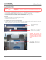
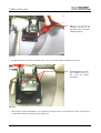
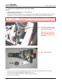
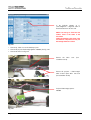
1
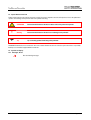
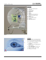
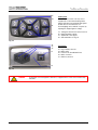
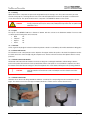
OCTOPUS 900
Service Manual
©HAAG-STREIT 06/2009 HS No. 7220054 Revision 02
HAAG-STREIT AG, Switzerland, Phone: +41 31 978 01 11, Fax: +41 31 978 02 82, [email protected]
HAAG-STREIT DEUTSCHLAND GmbH, Germany, Phone: +49 4103 709 02, Fax: +49 4103 709 370, [email protected]
HAAG-STREIT FRANCE, France, Phone +33 4 5009 0033, Fax +33 4 5009 7190, [email protected]
HAAG-STREIT UK, United Kingdom, Phone +44 1279 414969, Fax +44 1279 635232, [email protected]
HAAG-STREIT USA, INC., USA, Phone: +1 513 336 6858, Fax: +1 513 336 7828, [email protected]
OCTOPUS 900 Service Manual
HAAG-STREIT No. 7220054
TABLE OF CONTENTS
1
ITEMS SUPPLIED ..........................................................................................................................................................................3
2
SAFETY INSTRUCTIONS..............................................................................................................................................................4
2.1
General.................................................................................................................................................4
2.2
Ambient conditions ...............................................................................................................................4
2.3
Power Connection ................................................................................................................................4
2.4
Instrument Transportation ....................................................................................................................4
2.5
Special Notices in the Text...................................................................................................................5
2.6
Symbols on Display ..............................................................................................................................5
INTRODUCTION ............................................................................................................................................................................6
3.1
OCTOPUS Perimeter 900....................................................................................................................6
3.2
Octopus 900 control unit / PC ............................................................................................................11
WARRANTY AND PRODUCT LIABILITY ...................................................................................................................................12
4.1
Statutory requirements .......................................................................................................................12
4.2
Type plate...........................................................................................................................................13
4.3
Pictogram symbols .............................................................................................................................13
4.4
Support stand .....................................................................................................................................14
4.5
Safe system configuration in accordance with IEC / EN 60601-1 ......................................................15
4.6
Installation ..........................................................................................................................................19
INSTALLATION AND USAGE OF EYESUITE PERIMETRY SOFTWARE .................................................................................20
5.1
Installation, Exchange, Upgrade ........................................................................................................20
5.2
Releasing Program Options ...............................................................................................................21
PRINCIPLE OF OPERATION.......................................................................................................................................................22
6.1
Stimulus Intensity Control...................................................................................................................22
6.2
Current Control...................................................................................................................................22
6.3
Background Intensity Control .............................................................................................................23
6.4
Reference Point..................................................................................................................................23
6.5
Optics Module ....................................................................................................................................24
MAINTENANCE & REPAIR .........................................................................................................................................................25
7.1
Cleaning .............................................................................................................................................25
7.2
Housing ..............................................................................................................................................26
7.3
Power supply unit (1803900)..............................................................................................................28
7.4
Processor module (1804005) & Light controller board (1804205) .....................................................30
7.5
Camera module (1803800) ................................................................................................................32
7.6
Stimulus Projector (1803400) & Projector–fixation target (1803600).................................................36
7.7
Brightness measurement p.c.b. - stimulus (1804421) .......................................................................44
7.8
Aperture-/filter-module (1803500) ......................................................................................................45
7.9
LED Board - stimulus (1804525) ........................................................................................................46
7.10 Refractive lens holder module (1803250) ..........................................................................................47
7.11 Mirror Unit (1803300) ........................................................................................................................50
7.12 Headrest (1803200) ...........................................................................................................................51
7.13 Operating unit (1803170) ...................................................................................................................52
7.14 IR illumination (1803550) ..................................................................................................................53
7.15 Brightness measurement p.c.b. - background (1804421)..................................................................53
7.16 Background illumination (1803570)....................................................................................................54
SYSTEM MESSAGES..................................................................................................................................................................55
8.1
Messages (to be completed in revision 2)..........................................................................................55
8.2
Errors (to be completed in revision 2) ................................................................................................55
8.3
Resetting the IP address ....................................................................................................................59
APPENDIX....................................................................................................................................................................................60
9.1
Technical specifications .....................................................................................................................60
9.2
Instrument OCTOPUS 900 ................................................................................................................60
3
4
5
6
7
8
9
Page 2 / 53
HAAG-STREIT 08.06.09
1 ITEMS SUPPLIED
We congratulate you on choosing the OCTOPUS 900 – 90° visual-field perimetry of the latest generation. Depending on your order,
the items supplied are as follows:
− OCTOPUS 900
− Accessory kit
− optional support stand
Please check the delivery with care
1 x OCTOPUS Perimeter 900 1803000
1 x accessory kit, consisting of:
1 x patient-response button 1802439
1 x Ethernet switch 100Mbps 1803090
2 x Ethernet cable 1803094
1 x dust cover 1803061
1 x instruction manual 7220031
1 x CD with all Octopus 900 and EyeSuite Perimetry manuals 7220030
1 x eye occluder set 1802349
2 x spare fuses (T3.15 A / 250 V) 3000481
1 x support stand, consisting of:
1 x stand base 1801187
1 x O-900 table top 1803051
1 x set of accessories for support stand 1801194
1 x Visual Field Digest 1800092
Please keep all packaging material, as this can be reused for possible returns or when relocating.
OCTOPUS 900 Service Manual
Page 3 / 61
2 SAFETY INSTRUCTIONS
2.1 General
•
This instrument should only be used for the purpose as described in this manual.
•
Condensation can occur on the cold surfaces of the instrument if it has been transported from a cold environment to the
environment in which it will be used. In such a case, one should wait a couple of hours before turning on the instrument. Once
the temperature of the instrument is the same as the environment in which it has been placed and once it is dry you may
proceed with powering on the instrument.
•
The examination of the patients, the operation of the instrument and the interpretation of the results can only be performed by
persons who are experienced and who have been trained accordingly.
•
The instrument is to be installed on the height-adjustable table and employed in a dimly lit room in a medical area.
•
Keep the service manual there where persons who have been trained to repair the instrument can consult it at all times.
Guarantee claims can only be valid when the instructions in the service and user manuals are followed.
•
The doctor or operator is to instruct the patient in the safety instructions and check that they are observed.
•
Make sure that the instrument is connected only to the power source as defined on the perimeter rating plate. The on/off switch
does not separate the perimeter from the power lines. Before maintenance or cleaning work is performed, the power cord must
be removed from the wall socket.
•
The instrument should not be used in an explosive area. Do not store any flammable and explosive substances (such as
Alcohol, Petrol, Gas) near the instrument.
•
Removal of the housings and repairs to the instrument are permitted only by trained and authorized technicians. Considerable
danger for the operator and patients can be caused by improper repairs.
•
The dust-cover should be removed before turning on the instrument. If this is not done the light sources may get damaged due
to overheating.
On the other hand make sure that the instrument has been switched off before covering it with the dust-cover.
•
Only original replacement parts and original accessories are permitted for repairs.
2.2 Ambient conditions
•
Transportation
•
Storage
•
Working
Temperature
Air pressure
Relative Humidity
Temperature
Air pressure
Relative Humidity
Temperature
Air pressure
Relative Humidity
-40°C
500hPa
10%
-10C
700hPa
10%
+10°C
700hPa
20%
to
to
to
to
to
to
to
to
to
+70°C
1060hPa
95%
+55°C
1060hPa
95%
+40°C
1060hPa
75%
Environment
• Electric and electronic equipment must be separated from house waste! This equipment has been
introduced into the market after the 13th of August 2005.
• Disposal via your local collecting point or your Haag-Streit distributor.
• Thus it is ensured, that no harmful materials get into the environment and that valuable raw materials can
be reused again.
2.3 Power Connection
• Only use a conformed power cable. To reduce the risk of an electro shock, ensure that the power cable and plug is connected
with an earth lead.
• The cable, plug and ground connection on the wall socket must be 100% functional.
2.4 Instrument Transportation
Transport the instrument over large distances in the original packing. For short distances the instrument can be lifted by placing the
cupola towards ones chest, then place both hands behind the cupola (bottom section) and lift the instrument. See user’s manual
section 4.5.2.
Page 4 / 61
OCTOPUS 900 Service Manual
2.5 Special Notices in the Text
Further safety instructions are put into the text as needed. They vary in importance and should help reduce risks for the patient and
operator, avoid damage to the perimeter and insure optimal functioning.
!
ATTENTION
Instruction which must be followed to reduce risks to the patient and operator.
Warning
Instruction which must be followed to avoid damage to the perimeter.
Tip
Tip for insuring optimal functioning of the perimeter.
All OCTOPUS 900 functions are mentioned in this service manual. Certain functions are offered as options and there is a possibility
that they are not installed/ supplied with the instrument.
2.6 Symbols on Display
2.6.1 Messages, Errors
Error and warning messages
OCTOPUS 900 Service Manual
Page 5 / 61
3 INTRODUCTION
3.1 OCTOPUS Perimeter 900
The OCTOPUS 900 is an automatic projection perimeter for the examination of the whole field of sight (90°).
The system is divided into an examination element (OCTOPUS 900) and a control unit (notebook computer or PC). The examination
element communicates with the external PC via an Ethernet link. The OCTOPUS 900 is controlled using the software installed on the
PC. The perimeter may be controlled, if required, from a fully-lit adjacent room.
The integrated, automatic patient-fixation control function guarantees the reliability of diagnosis.
The OCTOPUS 900 is suitable for both clinical and investigational purposes, as its flexibility is virtually unlimited.
Thanks to its spherical, Goldmann-type cupola design, the OCTOPUS 900 tests the entire field of sight (up to 90° eccentricity). The
flexibility of this appliance allows it to deal with all perimetry tasks, both in the 30° and 90° range, using kinetic, static or flicker
perimetry.
New PC and perimetry software can be downloaded and updated by going to www.octopus.ch.
Page 6 / 61
OCTOPUS 900 Service Manual
Components
1
2
3
4
5
6
7
8
1
2
3
4
5
6
7
8
9
10
11
12
13
Top cover for stimulus projector
Front cover
Housing / Cupola
Mirror unit cover
Forehead rest
Display
Keypanel
Refractive lens holder with IR eye
illumination and refractive lenses
Chinrest
Response button
Response button connector
Type plate
Table height adjustment
9
10
11
12
13
Fig. 3-1
*
14
15
LCD display
The high-contrast TFT colour display allows the
video image to be viewed from an oblique angle.
The following messages are displayed on-screen:
16
14 Indication of a '' during stimulus
presentation.
15 Indication of an '', if the patient-response
button is pressed.
16 The crosshairs help to centre up the eye,
scale = 1mm intervals.
17 Display of left (OS) or right eye (OD)
18 Warning or error message
18
17
OD
Fig. 3-2
OCTOPUS 900 Service Manual
Page 7 / 61
19
22
20
Control panel
The control panel consists of an easy-to-use
keypad made of soft but hard-wearing rubber
material. All buttons are backlit with white light to
facilitate their use in a darkened room.
The backlighting can be disabled, if required, by
adjusting the display brightness settings.
21
19
20
21
22
Turning the refractive lens holder in and out
Display brightness settings
Adjustment of chin support
Start examination see Fig. 3-4
24
25
26
Connections
Fig. 3-3
27
23
24
25
26
27
Plug-in mains power unit
Mains switch
Holder for two T3.15AL/250V fuses
Mains connection
Ethernet connection
23
Fig. 3-4
DANGER
Page 8 / 61
All externally connected appliances and items of equipment must conform to the relevant safety
standards.
OCTOPUS 900 Service Manual
3.1.1 Housing
Optical and electronic components are protected from light and dust by five housing covers. They can be removed in just a few
moments for the purpose of servicing. Once the four screws in the back panel have been removed, the panel, hood and both IR
covers can be lifted out. The optical unit and electronic components of the OCTOPUS 900 are now accessible.
Always disconnect the appliance from the mains power supply before opening it. The removal of
housing components must only be carried out by suitably-trained specialists who are qualified and
authorized to do so.
DANGER
3.1.2 Cupola
The cupola of the OCTOPUS 900 has a diameter of 600mm, and thus conforms to the Goldmann standard. Test zones with
eccentricity up the following levels can be measured:
Nasal
Temporal
Superior
Inferior
•
•
•
•
60°
89°
60°
70°
3.1.3 Head rest
A wide, ergonomically-designed forehead rest allows the patient to remain in a comfortable position while examination is taking place.
3.1.4 Chinrest with sensors
The four buttons on the control panel are used to adjust the chin support, and thus the position of the head. Fine adjustment can also
be carried out from the control unit (PC) using the computer mouse. Sensors in the chin rest detect if the patient’s head is correctly
positioned.
3.1.5 Refractive lens holder module
An automatic swivel arm allows the refractive lens holder to swing in an out during the examination, without having to alter the
position of the patient. This swivel arm can be operated either from the control panel or on-screen with the computer mouse. Once
the refractive lens holder has been swung in, it can be fine-adjusted to the correct distance with respect to the eye being examined.
!
CAUTION
Always use the control-panel buttons on the device itself or on-screen control from the PC to
swivel the refractive lens holder in an out. Do not attempt to move the refractive lens holder
manually.
3.1.6 Refractive lens holder
Refractive lenses can be used during examinations within 30° eccentricity. The corresponding lenses are inserted before the test
begins. The refractive lens holder can be tipped forward by about 25° to make it easier to load the refractive lenses.
Fig. 3-5
OCTOPUS 900 Service Manual
Fig. 3-6
Page 9 / 61
3.1.7 Patient-response button
The patient-response button is connected to the underside of the head-support mounting (RJ11 jumper cable).
3.1.8 Mains connection
The Ethernet connection socket is located at the back of the appliance. Always use a crossed Ethernet cable for a direct PC
connection or a straight Ethernet cable for a connection through a network switch (shielded cable of category 5e), designed
to transmit reliably at 100MHz. This network connection is electrically isolated, with electrical strength of 4kV, in conformity with IEC /
EN 60601-1.
3.1.9 Light sources
LEDs are fitted for the purposes of periphery or background lighting, fixation help and stimulus. LEDs do not emit any heat, so no
active cooling system is required in this respect.
3.1.10 Light intensities
The intensity of stimulus and periphery light is measured by independent light-sensors and compared to the preset default values
every time the perimeter is switched on.
3.1.11 Stimulus
The stimulus light is projected indirectly into the cupola via a mirror unit. The user-defined programs offer a selection of five different
diaphragm diameters (Goldmann I - V). Stimulus intensity-damping is infinitely adjustable via the electronic control system. Stimulus
presentations of 100-500ms are permitted. A mechanical lock und optical damping elements are no longer required.
White stimulus for W/W perimetry and optional blue und red stimulus for B/Y and R/W are possible.
Stimulus intensity is detected by a light sensor, which also serves as a reference point for the system of coordinates for test
locations. The stimulus LED has a service life of >20,000h and is thus maintenance-free.
3.1.12 Periphery or background lighting
White background brightness amounts to 31.4 or 4asb for W/W perimetry. You can also select a yellow background with 31.4asb for
B/Y perimetry. Background brightness is based on two light sources, each fitted with several LEDs. The background LEDs have a
service life of >20,000h and are thus maintenance-free. Background brightness is detected by a separate light sensor.
3.1.13 Fixation marks
Three different fixation marks can be selected and their brightness infinitely adjusted by electronic means. The light source is a
maintenance-free green LED with a service life of >20,000h.
centre point
Page 10 / 61
cross mark
circle
OCTOPUS 900 Service Manual
3.1.14 Fixation control
The eye being examined is illuminated with IR LEDs, photographed by a CMOS camera and shown on the LCD display. The built-in,
automatic fixation-control function guarantees the reliability of diagnosis. Precise positioning of the eye being examined is carried out
by motorized fine-adjustment of the chin rest.
3.1.15 Diagnosis data
All diagnosis data are transferred via the Ethernet connection to the control unit (PC / Laptop) for processing and saving to a
database. The use of a second Ethernet connection (LAN card) allows these data to be exported to a server. Diagnosis data can
also be printed out using a printer connected to the control unit.
3.2 Octopus 900 control unit / PC
A standard PC can be used as a control unit for the Perimeter. The control-system software runs on WINDOWS XP.
3.2.1 Minimum PC requirements
•
•
•
•
•
Pentium III / 1.7GHz
512 MB RAM
40GB hard disk
CD-ROM / DVD
T100 (100MHz) Ethernet interface
Power connector socket with fuse holder on the electronics box.
Fig. 3-7
3.2.2 OCTOPUS 900
Handle the instrument using both lower housing halves to lift it out of the packing. Two ribbed grips hinder sideways slipping.
OCTOPUS 900 Service Manual
Page 11 / 61
4 WARRANTY AND PRODUCT LIABILITY
•
The appliance and its accessories are made of high-quality materials and manufactured to the latest technical standards. They
left our factory in a perfect state of repair. If an incident should occur however, please contact your dealer.
•
The manufacturer supplies the appliance with a one-year warranty, counted from the date of purchase. The warranty covers
malfunctions and defects attributable to faulty materials or design. The warranty does not cover malfunctions or defects arising
from incorrect use or external factors.
•
Any attempt to carry out unauthorized repairs will immediately void all warranty liability.
•
Continued use of a product that has been damaged by incorrect operation can lead to personal injury. The manufacturer will
accept no liability whatsoever in such cases.
•
Before unpacking the appliance, check the outside of the packaging for signs of incorrect handling and possible damage. If you
do detect such damage, please notify the carrier who carried out delivery, and unpack the appliance in the presence of a
representative from the transport firm concerned. You should then make out a report detailing any damage detected. The
report should be signed by you and the carrier’s representative.
4.1 Statutory requirements
•
The regulations are according to the valid ‘CE declaration of Conformity’ for this specific instrument.
•
A copy of the declaration of conformity for the product concerned can be requested at any time from Haag-Streit.
•
Statutory requirements regarding accident prevention should be respected.
EMC
The OCTOPUS 900 meets the electromagnetic compatibility requirements of IEC / EN 60601-1-2. The appliance is designed to keep
the generation and emission of electromagnetic interference to a level that does not affect the normal operation of other items of
equipment. The appliance is likewise designed to provide a certain level of resistance to outside sources of electromagnetic
interference.
Page 12 / 61
OCTOPUS 900 Service Manual
4.2 Type plate
Read through the instruction manual with special care
Manufacturer
Serial number
Appliance number
Product classification type B
Date of manufacture
Do not push
2
3
41
56 7
4.3 Pictogram symbols
Ground connection lead.
Do not push. The appliance is liable to tip over if pushed from the side.
This appliance conforms to European Directive 2002/95/EC (RoHS).
OCTOPUS 900 Service Manual
Page 13 / 61
4.4 Support stand
An electrically adjustable support stand (available as an option) allows the appliance to be adjusted easily and smoothly to the
individual patient. The support stand offers ample legroom and is wheelchair-compatible.
Support stand
1
Table top with mountings for patient-response button
2
Electrical connection box
3
Patient-response button
4
Electrically-actuated lifting column
5
Stand feet with castors
1
2
3
4
5
Fig. 4-1
6
7
Electrical voltage selector in electrical connection box
Power socket for connection of the OCTOPUS 900
6
7
DANGER
Check that the mains voltage is correct
before connecting to the power supply.
Fig. 4-2
Mains connection with fuse holder on electrical connection box.
Fig. 4-3
ON/OFF switch on electrical connection box.
DANGER
Fig. 4-4
Page 14 / 61
Take special care, especially when dealing
with patients in wheelchairs, to ensure that
the table top does not come into contact with
the patient’s legs.
OCTOPUS 900 Service Manual
4.5 Safe system configuration in accordance with IEC / EN 60601-1
4.5.1 OCTOPUS 900 standard configuration (single PC)
Always set a network switch between the Octopus 900 and the PC. This ensures correct data flow
OCTOPUS 900 Service Manual
Page 15 / 61
4.5.2 Octopus 900 in small networks (no dedicated server)
Never attach the Octopus 900.or its control PC to a hub or to a wall plug directly. Always use a local network switch for the
connection.
Page 16 / 61
OCTOPUS 900 Service Manual
4.5.3 Octopus 900 in standard networks (with dedicated server)
Never attach the Octopus 900 or its control PC to a hub or to a wall plug directly. Always use a local network switch for the
connection.
OCTOPUS 900 Service Manual
Page 17 / 61
Observations
1 If the control unit (notebook computer or PC) and printer are farther than 1.5m from the OCTOPUS 900, there is no need for a
safety isolating transformer conforming to IEC 60601-1 / EN 60601-1.
If a medically-approved control unit or a control unit with network element approved for medical use is in operation without a
printer or optional LAN connection, neither a safety isolating transformer nor a distance of > 1.5m from the OCTOPUS 900 are
required.
For safety reasons, you are however recommended to maintain the minimum distance of 1.5 m wherever possible. All other
non-medical appliances and items of equipment must be operated via a safety isolating transformer.
Page 18 / 61
OCTOPUS 900 Service Manual
4.6 Installation
4.6.1 Support stand
The support standard is supplied in a separate package. Assemble the support stand according to the instructions supplied with it,
and ensure that you select the correct mains voltage before connecting the power supply lead.
4.6.2 OCTOPUS 900
Transporting and relocating the appliance (over short distances only)
a) Stand in front of the device and grasp it by the cupola with both hands before lifting (Fig. 4-5).
b) Stand to one side of the appliance, with one hand on the front cover and the other at the back. Then take a firm hold and lift
(Fig. 4-5; Fig 4-6 & Fig. 4-7).
Fig. 4-5
Fig. 4-7
Fig. 4-6
Push the patient-response button into its connection socket.
The connection socket for the response button is
located at the bottom of the front cover. The retaining
catch on the connection plug of the response button
faces forwards
CAUTION
!
Fig. 4-8
The RJ11 plug is designed for
connection of the patient-response
button only. Do not use it with any
other item.
Fig. 4-9
Front cover
Cupola housing
Connection plug with retaining catch
− Push in the connection plug until you hear the retaining catch click into place. To remove the response button, push the retaining
catch towards the headrest and pull the cable downwards.
− Connect the OCTOPUS 900 and PC with the Ethernet cable or integrate the Perimeter appliance into a LAN. You are
recommended to use a direct connection, as variations due to network load can affect the diagnostic performance of the
appliance. Further information can be found in section 4.4.
− An electrically adjustable support stand (available as an option) allows the appliance to be adjusted easily and smoothly to the
individual patient. The support stand offers legroom and is wheelchair-compatible.
OCTOPUS 900 Service Manual
Page 19 / 61
5 INSTALLATION AND USAGE OF EYESUITE PERIMETRY SOFTWARE
5.1 Installation, Exchange, Upgrade
Instructions on how to use the appliance for diagnostic purposes and a description of the EyeSuiteTM user software are included in a
separate manual.
Fig. 5-1
Page 20 / 61
OCTOPUS 900 Service Manual
5.2 Releasing Program Options
Some of the functions of the OCTOPUS 900 are offered as options and are not accessible in the basic version of the software.
Basically all the functions are present in the software, but some can only be made accessible with a code. This code is delivered by
HAAG STREIT and is then entered by the customer or the service technician into the instrument. Information about such additional
functions can be obtained directly from HAAG STREIT or from your representative.
Note: All options are free of charge for the first 30 days. After this time period, it is necessary to enter a dongle code or else the
options can not be used.
5.2.1 Dongle Code
[Configuration / Setup] [Options]
Fig. 5-2
IMPORTANT:
Customer
HAAG STREIT AG
Customer
The 'Dongle code' function is only used, when additional program options have been purchased.
− Select the options you wish to purchase and press ‘Print options’
− Sends the generated output with serial no., PC-ID and address to HAAG STREIT or the
representative and orders the desired supplementary option(s).
− Based on the PC-ID, the new dongle code is computed and given to the customer.
− Enters the complete new dongle code into the entry field and press ‘Save dongle code’.
− Before saving, the parameters are verified by the system. A faulty dongle code will not be saved.
The entry field will be cleaned. Repeat by entering the correct dongle code.
− Restart EyeSuite to apply the new settings.
IMPORTANT: The additional functions are only made accessible when the dongle code is entered
without any mistakes into the instrument it was created for.
OCTOPUS 900
− The new additional option(s) are accessed via the graphical user interface.
5.2.2 The Results of Code Mistakes
Every dongle code is unique and only valid for a specific PC/ Notebook. Mistakes made while entering it or the entering of it into the
false PC / Notebook (false PC-ID) have the consequence that only the basic functions are then accessible. Changing to the old code
is possible at all times.
OCTOPUS 900 Service Manual
Page 21 / 61
6 PRINCIPLE OF OPERATION
6.1 Stimulus Intensity Control
The required dynamic range of the stimulus intensity of 46 dB (1:40'000) is achieved with a combined control mode:
a) Two point current control (I)
b) Pulse-width modulation (S)
I (LED)
S (MOD)
Principle of
stimulus generation
Stimulus LED
Fig. 6-1
6.2 Current Control
Two current reference values (operating points) are ascertained during the stimulus calibration procedure:
− Operating point OP1:
− Operating point OP2:
0dB
20dB
(max. stimulus intensity)
(max. stimulus intensity/100)
Thus the entire dynamic range is divided into two segments:
− Segment 1 / operating point OP1:
− Segment 2 / operating point OP2:
20dB ... 0dB
40dB ... 20dB
I (LED)
I (LED) OP1
Operating point 1
I (LED) OP2
Operating point 2
L (asb)
Lmin = 40dB
Fig. 6-2
Lmax/100 = 20dB
Lmax = 0dB
Stimulus LED current control
6.2.1 Pulse-width Modulation
A typical stimulus of 100ms duration is formed by a burst of 20 x 5ms pulses. The width (ratio LED switch-on/LED switch-off time) of
the 20 pulses can be increased or decreased by processor control in steps of 0.242µs (20665 steps for 5ms). With a longer switchon time the LED is emitting light for a longer time period, resulting to the human eye, which has an integrating characteristic, in an
impact of higher brightness. Pulse-width and light emission are proportional. Pulse-width modulation and stimulus duration are
controlled by the microprocessor software through logic timer signals.
Page 22 / 61
OCTOPUS 900 Service Manual
I (LED)
Stimulus duration = 100ms (20 pulses)
Pulse of 5ms
S (MOD) = on
S (MOD) = off
OP1
brighter
darker
brighter
Pulse 20
darker
Pulse 2
OP2
brighter
Pulse 1
darker
t
Fig. 6-3 Stimulus LED pulse-width modulation
6.3 Background Intensity Control
The light source for the background illumination consists of a number of white LEDs. During initialization of the perimeter the
background brightness is measured by a photo sensor and controlled by a DAC value (31.4 asb). Pulse-width modulation is used
only for background illumination 4 asb.
6.4 Reference Point
During initialization of the perimeter the stimulus projection unit is centred to the optical system (position x/y = 0/0). The photo sensor
for stimulus calibration is used as reference point.
OCTOPUS 900 Service Manual
Page 23 / 61
6.5 Optics Module
Stimulus
Fig. 6-4 Optics module
1
2
3
4
5
6
7
8
9
LED
Condenser lens
Diaphragm for Stimulus Size
Color Filter
Diaphragm / Filter module
Achromate lens
Deflection mirrors for stimulus focus
Deflection mirror
Stimulus projector
10
11
12
13
XY-deflection mirror
Mirror unit
Cupola
Stimulus
S
Way compensation
1
2
3
4
LED
Lenses 1
Diaphragm for fixation target
Lenses 2
5
6
7
Projector-fixation target
Deflection mirror
Cupola surface
1
Camera chip
4
Camera module
2
3
Achromate lens
Cold light mirror
5
Patient eye
Fixation target
Fig. 6-5 Optics module
Camera
Fig. 6-6
Page 24 / 61
OCTOPUS 900 Service Manual
7 MAINTENANCE & REPAIR
!
WARNING
Before opening the instrument make sure that the mains cable is separated from the instrument.
!
WARNING
Some of the modules need alignment after being exchanged, therefore it is important to go
through all the steps described in exchanging the module that needs to be replaced.
WARNING
Electronic circuits of the OCTOPUS 900, particularly the processor module, light controller board,
camera board and the brightness measurement p.c.b. are all sensitive to electrostatic charges.
Keep all modules in static shielding bags for storage, transportation and shipping..
Whenever possible, field repairs of the OCTOPUS 900 should be restricted to module exchange. The sub module (parts) causing a
problem should be localized with the help of the service manual and error list. It should then be replaced with an exchange module.
The following tools are a prerequisite to be able to carry out repairs on the OCTOPUS 900 Perimeter:
- Set of torx screwdrivers (the sizes in this manual refer to the screwdriver size)
- Phillips screwdriver
- Screwdriver size 2 and 3
- Universal digital voltmeter, range 200mV to 250V
It is recommended that technicians trained on the OCTOPUS 900 have the alignment gauge to adjust the camera. The alignment
gauges 0520057 and 0520058 are both needed to align the stimulus projector. These gauges are necessary if one wants to carry out
repairs on this module without having to replace it.
Alignment gauge for the camera
Alignment gauge for the stimulus projector
Alignment gauge for the refractive lens holder
Alignment gauge for the mirror on the mirror unit
-
Alignment gauge for the refractive lens holder (only with 0520055)
Alignment gauge for the camera
Alignment gauge for the stimulus projector
Alignment gauge for the mirror on the mirror unit
(0520054)
(0520055)
(0520057)
(0520058)
7.1 Cleaning
It is recommended to keep the instrument covered with the dust cover when not in use. If necessary use a soft cloth to dust off dirt
particles. More obstinate dirt particles can be removed using a soft cloth dampened slightly with water or alcohol.
Cleaning materials:
• Can of compressed air
• Lens tissue
• Lens cleaner (diluted alcohol)
• Cotton swabs
OCTOPUS 900 Service Manual
Page 25 / 61
7.1.1 Patient response button (1802032), headrest (1803200), and eye occluder (1802349)
The above mentioned plastic parts can be cleaned without a problem. In order to keep them hygienically clean, they should be
cleaned whenever a new patient is to be examined. This can be done with a cloth or with cotton dampened with alcohol.
7.1.2 Monitor Screen
Finger prints and dust can be removed with a moist, soft cloth.
7.1.3 Cupola
The inside of the cupola has a special coating. This special coating is very important for optimal results when doing a visual field
examination. It is NOT necessary to clean this surface regularly. Generally we recommend cleaning the surface about twice a year.
When cleaning the inside of the cupola, one needs to take great care! We recommend you to get rid of the dust by using a dry cloth.
(A wet cloth will cause brown streaks inside the cupola which can cause an inaccuracy in the examination). Stains can be removed
by using a mild soap and soft cleaning cloth after having removed the dust. Never apply too much pressure when cleaning with a
cloth or else it will shine which is not good!
7.2 Housing
-
Front cover
Back cover
IR-cover (left)
IR-cover (right)
Top cover
!
NOTE:
(1803152)
(1803154)
(1803155)
(1803156)
(1803157)
If the 'housing' is removed, the perimeter will only initialize and calibrate correctly if it is
placed in an entirely dark environment. The covers can temporarily be put back in place
for its operation and to run the 'service programs' such as the 'general test' in a semidark room.
Removal
• First remove the back cover (1803154) by removing the 4 torx screws, torx screwdriver size 25. See Fig. 7-1
Page 26 / 61
OCTOPUS 900 Service Manual
Top cover (1803157)
4 screws torx, M5x16 (1008509), to remove the back
cover, IR-cover left/right and top cover
Back cover (1803154)
Front cover (1803152)
Housing (1803151)
4 Screws torx, M5x20, (1008508), to remove the front
cover
IR-cover left 1803155
IR-cover right 1803156
Fig. 7-1
OCTOPUS 900 Service Manual
Page 27 / 61
To remove the top cover, use both hands to pull out
the cover from the 2 plastic fastening locks.
Fig. 7-2
• Once the screws have been removed, you can remove the back cover.
• Remove the top cover by pulling it slightly in a backward movement. Use both hands to pull out the cover from the 2 plastic
fastening locks. See figure Fig. 7-2
• The IR-cover (left) and IR-cover (right) can now be removed by sliding them out the back. Place the covers on a clean surface.
• The front cover (1803152) is also held in place with 4 torx screws, M5x16 (1008509) mounted from the back of the cupola.
NOTE: This cover can be removed without having to remove the other covers! With the torx screwdriver size 25 you can loosen
the screws and simply pull away the front cover. Place the cover on a clean surface.
Reassembly
Reassemble in reverse order to removal.
Check
Once re-assembled check that the screws have been tightened and make sure that the covers are clean.
7.3 Power supply unit (1803900)
!
Warning:
Before removal, always unplug the main power cable from the OCTOPUS to prevent
electrical shock!
Removal of the power supply unit
•
•
•
•
•
Unplug the main power cable from the back of the OCTOPUS 900
Remove the back cover (1803154) by removing the 4 torx screws, M5x16 with a torx screwdriver size 25. See chapter 7.2
Remove the cables from the unit. See Fig. 7-3
Remove the ground connector from the power supply unit. See Fig. 7-4
Slide out the power supply unit in the direction of the arrow seen in Fig. 7-3
Reassembly
Reassemble in reverse order to removal.
Page 28 / 61
OCTOPUS 900 Service Manual
Cable PS1-MB (1804720)
Cable PE Front (1804723)
Cable PS2-MB (1804721)
LAN Cable (1804700)
Power Supply unit (1803900)
Fig. 7-3
Remove the ground connector
Fig. 7-4
Remove the LAN cable
Fig. 7-5
OCTOPUS 900 Service Manual
Page 29 / 61
7.4 Processor module (1804005) & Light controller board (1804205)
Removal
•
•
•
•
•
Remove the back cover (1803154) by removing the 4 torx screws, M5x16 with a torx screwdriver size 25. (See chapter 7.2).
Remove the cable connected to the camera board. (cable MB-CAM - 1804702) by pulling it out of the brown clamping fixture.
NOTE: loosen the brown clamping fixture to be able to pull out the flat cable! (See
Fig. 7-7 Camera board).
Remove all the other cables from the processor module (see Fig. 7-6 Mainboard and Light Controller Board). The connections
are all marked on the processor module, making it easy to reinsert the cables in the correct position when reassembling the
module. Note: All flat cables have contacts on both sides as from serial number 641.
Pull the processor module off the 4 plastic knobs (in each corner) as well as removing the light controller board from the bottom
2 plastic knobs. The processor board can now be removed easily by pulling it out of the connector on the light controller board.
Pull it out in a downward movement.
Cable LC (1804718) to the light sources
stimulus, background and fixation target
Light controller board (1804205)
Cable MB - DBMU (1804703) to the
distribution board for mirror unit (1804345)
Cable MB – DBST (1804704) to the
distribution board for stimulus projector
Processor module (1804005)
Cable IR (1804719) for IR-illumination left and
right
Cable MB-DBCR (1804705) to distribution
board for chin rest
Cable PS1-MB (1804720) Power supply
5/12V
Cable PS2-MB (1804721) Power supply 21V
Cable SCSI II (1802780) to the operating unit
(1803170)
Fig. 7-6 Mainboard and Light Controller Board
LAN-Cable (1804700)
Camera board (1804105)
Cable MB-CAM (1804702)
The blue isolation must be visible, facing up!
Do not insert upside down!
Brown connector which needs to be loosened,
to be able to pull out the flat cable
Warning: be careful and gentle or else the
clamping fixture will break off!
Torx screws to remove the camera board,
(torx screwdriver size 8)
Fig. 7-7 Camera board
Page 30 / 61
OCTOPUS 900 Service Manual
Reassembly
!
NOTE:
When replacing a processor board it is important to re enter the serial number or else the
OCTOPUS will not support any options that have been included!
• Parameters are stored in the brightness measurement boards, therefore no values have to be re entered except for the serial
number. This is only necessary when replacing the processor board. Entering the serial no. is simple. In the EyeSuite software
go to: Perimetry – Service/ Diagnostic – Connection and then enter the serial no. See Fig. 7-8.
Enter the serial no. of the OCTOPUS 900, then press
enter.
Enter a number such as 999 as a sign, then press
enter.
Save to Octopus as soon as this symbol has been
activated. (It is only activated once a serial number
and sign has been entered).
Fig. 7-8
Reassemble in reverse order to removal.
Check
• Are all connectors attached correctly?
• After reassembly, run the 'general test' with the EyeSuite software to verify faultless operation.
Removal of the light controller board (1804205)
• Remove the back cover (1803154) by removing the 4 torx screws, M5x16 with a torx screwdriver size 25. (See chapter 7.2)
• Remove the cable leading to the light sources stimulus, background and fixation target (see Fig. 7-6 Mainboard and Light
Controller Board).
• Pull the light controller board off the 4 plastic knobs (in each corner) as well as removing the processor module from the top 2
plastic knobs. The light controller board can now be removed easily by pulling it out of the connector on the processor module by
pulling in an upward movement.
Reassembly
Reassemble in reverse order to removal.
OCTOPUS 900 Service Manual
Page 31 / 61
7.5 Camera module (1803800)
Removal of the camera module
!
•
•
•
•
NOTE:
After removing the camera, it is essential to carry out the alignment procedure described
in step 7.5.1
Remove the back cover (1803154) by removing the 4 torx screws, M5x16 with a torx screwdriver size 25. (see chapter 7.2)
Remove the cable MB-CAM (1804702) from the brown connector. (see Fig. 7-7 Camera board)
Remove the 2 torx screws on the camera board (1804105) with screwdriver size 8.
Place the camera board on a clean surface. Make sure that the camera chip does not get scratched
Reassembly
• Make sure that the CCD-chip is clean. Clean it gently, if necessary.
• Reassemble in reverse order to removal.
7.5.1 Alignment of the camera after replacement or removal
• Insert the ‘camera/ refractive lens holder’ alignment gauge, part no. 0520055. See Fig. 7-09, Fig. 7-10 and Fig. 7-11 below.
NOTE: This procedure is done more easily if the front cover has been removed.
Camera alignment gauge,
(0520055)
Additional part to align the
refractive lens holder ( 0520054)
Fig. 7-9
WARNING: When mounting and
removing the alignment gauge, great
care should be taken not to scratch
the cupola. DO NOT drop it into the
cupola!
The alignment gauge can be
positioned with or without removing
the front cover
Fig. 7-10
Page 32 / 61
OCTOPUS 900 Service Manual
!
WARNING:
When mounting and removing the alignment gauge, great care should be taken not to
scratch the cupola. DO NOT drop it into the cupola!
The two plastic plugs holding the
alignment gauge MUST be positioned
in the holes to obtain the correct
height
Fig. 7-11
• In the EyeSuite software (PC) go to the menu ‘Perimetry’, ‘Service Diagnostic’, ‘Monitoring’ and press the ‘OD’ button to switch
on the camera (The OCTOPUS 900 must be connected to a PC or laptop via the ethernet cable for this procedure).
Press ‘Monitoring’ and
press the ‘OD’ button to
view the eye image.
Fig. 7-12 EyeSuite setting to view camera image
OCTOPUS 900 Service Manual
Page 33 / 61
Example what one can expect
to see on the screen. In this
example the position is NOT
correct and needs to be
adjusted correctly.
Fig. 7-13 Cross fixation
• With the 2 torx screws (torx screwdriver size 20) one can adjust the position of the camera (left/right & up/down) so that the
position of the fixation on the alignment gauge is exactly on the cross fixation on the monitor screen. See Fig. 7-15.
We recommend the use of a
laptop while adjusting the
camera. In this way it is easier
and more precise to adjust it to
the centre.
Always make use of the service
manual
when
making
adjustments. Follow the service
manual step by step!
Fig. 7-14
Page 34 / 61
OCTOPUS 900 Service Manual
With the 2 torx screws (torx
screwdriver size 20) one can
adjust the position of the camera
(left/right & up/down)
Fig. 7-15
• By adjusting the 2 torx screws (torx screwdriver size 8), one can correct the vertical/ horizontal tilt. See Fig. 7-16.
By adjusting the 2 torx screws
(torx screwdriver size 8), one
can correct the vertical/
horizontal tilt.
Fig. 7-16
• After the above mentioned adjustment, it is recommended to check the position of the refraction lens holder, seeing the tool is
already inserted. Refractive lens holder: refer to chapter 7.10.
OCTOPUS 900 Service Manual
Page 35 / 61
7.6 Stimulus Projector (1803400) & Projector–fixation target (1803600)
Removal
• Unplug the main power cable from the back of the OCTOPUS 900.
• Remove the housing. See chapter 7.2
• Remove the mirror unit by removing the 2 torx screws holding the mirror unit with the plate mounted between the mirror unit and
the stimulus projector, from the top. See 7.17. First unplug all the connectors from the mirror unit and hold the mirror unit.
!
WARNING:
When unscrewing the two screws you MUST hold the Mirror unit, so that it will NOT fall
into the cupola!
Remove the 2 torx screws (size 25)
to be able to remove the mirror unit
together with the holding plate.
NOTE: When unscrewing the two
screws you MUST hold the Mirror
unit, so that it will NOT fall into
the cupola!
Fig. 7-17
Mirror unit with holding plate
Fig. 7-18
•
•
•
•
Remove the 4 torx screws (torx 25) holding the projector in the 4 corners with the 4 red rubber washers. See Fig. 7-20.
Remove the projector–fixation target (part No. 1803600). See Fig. 7-22.
Remove the cables plugged into the distribution board on the stimulus projector.
Place the unit on a clean surface.
Page 36 / 61
OCTOPUS 900 Service Manual
Stimulus projector (1803400)
Fig. 7-19
Remove 4 torx screws (2 in the
back and 2 in the front) (torx 25)
holding the projector in the 4
corners with the 4 red rubber
washers.
The screws should be replaced
with Loctite 243 to prevent them
from falling out.
Fig. 7-20
Reassembly
Reassemble in reverse order to removal.
7.6.1 Realignment
• Make sure that the stimulus projector and mirror unit are back in place and that the connectors are connected.
• Power on the Perimeter.
• Go into the EyeSuite software, go to service/diagnostic – diagnostic then move the stimulus to the centre. Turn on the stimulus
LED, set the DAC and pulse values to maximum and the stimulus size to size V. See Fig. 7-21.
OCTOPUS 900 Service Manual
Page 37 / 61
In the EyeSuite software go to
‚service/diagnostic’ – ‚diagnostic’. Turn on
the stimulus and move it to the ‚field’.
NOTE: You must go to ‘Field’ and not
‘Center’. ‘Field’ is the centre of the
visual field.
Setting the stimulus to the centre of the
visual field is of importance to carry out
the settings which are to follow.
Fig. 7-21
• Remove top , black cover on the stimulus projector
• Remove the projector–fixation target (part No. 1803600). See Fig. 7-22
• Remove the mirror. See Fig.7-24.
Remove the black
screwdriver size 10)
cover
(torx
Remove the ‚projector – ‚fixation target’
which is held in place with 1 torx screw
(torx screwdriver size 25)
Fig. 7-22
Projector–fixation target, part no.
1803600
Fig. 7-23
Page 38 / 61
OCTOPUS 900 Service Manual
Remove the mirror (Torx screwdriver size 10)
Fig. 7-24
• Mount the alignment gauge for the stimulus projector unit in the holes from which the projector- fixation target was removed.
See Fig. 7-25.
Mount the alignment gauge (part no. 0520057) for
the stimulus projector unit in the holes from which
the projector- fixation target was removed.
Fig. 7-25
Check that the light spot is centred!
Screwdriver (size 2) to adjust the stimulus light
to the correct up/down position
Screwdriver torx 1.5 to adjust the stimulus light
in a left/right position
Fig. 7-26
OCTOPUS 900 Service Manual
Page 39 / 61
The stimulus light must be centred
with stimulus size V
Fig. 7-27
• Once the alignment has been carried out (see Fig. 7-26 and Fig. 7-27), remove the alignment gauge and replace the mirror.
• Mount the alignment gauge for the mirror unit (part no. 0520058) on the mirror of the mirror unit. See fig. 7-28.
Alignment gauge for the mirror on
the mirror unit. (part no. 0520058)
Fig. 7-28
Look through the fixation target hole and
adjust the mirror with the screws on the
mirror, to the centre of the mirror on the
mirror unit.
Page 40 / 61
OCTOPUS 900 Service Manual
Fig. 7-29
Use a allen key (size 1.5) to adjust the the 2 screws on
the side, to align the stimulus light in a up/down
position.
Use screwdriver size 2 to adjust the stimulus light in a
left/right position.
Fig. 7-30
A perfectly aligned mirror. The stimulus light is
centred to the middle of the mirror on the mirror unit.
(alignment gauge part no. 0520058)
Fig. 7-31
• Once the mirrors have been aligned (refer to Fig. 7-29, Fig. 7-30 and Fig. 7-31 replace the ‘projector-fixation target and align it.
Refer to the next chapter: 7.6.2.
OCTOPUS 900 Service Manual
Page 41 / 61
7.6.2 Aligning the tilted mirror – 1803610 (fixation target)
Projector – fixation target (1803600)
Fig. 7-32
• In the EyeSuite software go to service/ diagnostics – diagnostics and move the stimulus to the visual field centre. Set the
stimulus size to II and the stimulus colour to red. See Fig. 7-33
In the EyeSuite software go to ‚service/diagnostic’ –
‚diagnostic’. Turn on the stimulus and move it to
‘Field’. Set the stimulus size to II and the colour to
red. The DAC value and Pulse must be set to the
maximum value.
NOTE: You must go to ‘Field’ and not ‘Center’.
‘Field’ is the centre of the visual field.
Fig. 7-33
• Remove the front cover to access the front plate. Through the gap in the front plate one can adjust the position of the mirror
(used for the correct alignment of the fixation target). See Fig. 7-34.
Adjust the fixation in a left/right movement with an allen
key size 1.5
Adjust the fixation in an up/down movement with a
screwdriver size 2
Fig. 7-34
Page 42 / 61
OCTOPUS 900 Service Manual
Bad alignment
Bad alignment of the green fixation target set to
the visual field centre by using the stimulus size IV
Red stimulis size IV
Green fixation target
Fig. 7-35
Good alignment
Stimulus light spot IV in the
visual field centre
An aligned fixation
(central point).
target
Fig. 7-36
• Once all the alignments have been carried out (refer to Fig 7-32, Fig. 7-33 and Fig. 7-34), replace the housing and carry out a full
general test and run at least one examination.
OCTOPUS 900 Service Manual
Page 43 / 61
7.7 Brightness measurement p.c.b. - stimulus (1804421)
Removal
• Remove the housing (See chapter 7.2).
• Remove the black plate covering the stimulus projector (3 torx screws, size 10). See Fig. 7-37.
• Remove the brightness measurement p.c.b. by unplugging the cable and unscrewing the two torx screws (size 10). See Fig. 7-38.
Remove the 3 torx screws, size 10 to remove
the black cover on the stimulus projector.
Fig. 7-37
Unplug the cable from the connector
Brightness measuremnet p.c.b. (stimulus)
Remove the 2 torx screws, size 10
Fig. 7-38
Reassembly
Reassemble in reverse order to removal.
!
Page 44 / 61
NOTE:
No calibration is required. The calibration values are stored inside the memory on the
brightness measurement p.c.b.
OCTOPUS 900 Service Manual
7.8 Aperture-/filter-module (1803500)
Removal
• Remove the housing (See chapter 7.2).
• Remove the black plate covering the stimulus projector (3 torx screws, size 10). See Fig. 7-37.
• Remove the 2 flat cables from the distribution board, leading to the aperture-/filter-module. See Fig. 7-39.
• Remove the torx screw (screwdriver size 20) holding the aperture-/filter-module. See figure Fig. 7-40.
• Remove the module and place on a surface.
Remove the 2 flat cables from the distribution
board, leading to the aperture-/filter-module.
Fig. 7-39
Remove torx screw (size 20)
Fig. 7-40
Filter plate
Aperture plate
Fig. 7-41
Reassembly
• Reassemble in reverse order.
OCTOPUS 900 Service Manual
Page 45 / 61
7.9 LED Board - stimulus (1804525)
Removal
• Remove housing, see chapter 7.2
• Remove the black plate covering the stimulus projector (3 torx screws, size 10). See figure Fig. 7-37
• Remove the aperture-/filter-module. See previous chapter 7.8.
• Unplug the cable connected to the distribution board. See figure Fig. 7-42.
• Unscrew the 2 torx screws (torx screwdriver size 8). See Fig. 7-42.
• Remove the module and place on a surface.
!
NOTE:
The stimulus LED is very sensitive. Do not clean with alcohol or petroleum products.
Clean with a window-cleaner substance, use a cotton swab. The Optical lens is not
allowed to get scratched!
Unscrew the 2 torx screws with a
torx screwdriver size 8
Unplug the cable connected to
the distribution board
Fig. 7-42
!
NOTE:
Check the alignment of the optics after dismounting the LED board. See chapter 7.6.1
Reassembly
• Reassemble in reverse order to removal.
Page 46 / 61
OCTOPUS 900 Service Manual
Front part of the Instrument
BG-Illumination (1803570)
Mirror Unit (1803300)
Tilted Mirror for Fixation Target
(1803610)
Brightness measurement
background (1804401)
p.c.b.
Operating Unit (1803170)
Refractive lens holder (1803250)
Head rest (1803200)
Distribution Board Chin Rest
(1804320)
Fig. 7-43
7.10 Refractive lens holder module (1803250)
Removal of the refractive lens holder
• Remove the front cover (4 torx screws, size 25). See chapter 7.2.
• Unplug the cables leading from the distribution board to the refractive lens holder. See Fig. 7-44.
• Remove the 2 torx screws holding the refractive lens holder. See Fig. 7-45.
• Remove the refractive lens holder and place on a clean surface.
Unplug the connectors from the
distribution board
Remove the cable.
WARNING: When removing the
cable, make sure not to rip it out
of the socket. Gently move it out
by using a small screwdriver! If
one does not take note of this,
one will pull out the thin wires.
Fig. 7-44
OCTOPUS 900 Service Manual
Page 47 / 61
Remove the 2 torx screws (size 20) which holds the
refractive lens holder
Fig. 7-45
Reassembly
Reassemble in reverse order to removal.
7.10.1 Realignment
• Position the camera alignment gauge together with the additional part. See figure Fig. 7-9, Fig. 7- & Fig 7.11.
• Position the refractive lens holder in the upright position so that the refractive lens holder itself is in the middle of the alignment
gauge. See Fig. 7-46 and Fig. 7-49.
• Adjust the position so that the refractive lens holder is centred by adjusting the screw (screwdriver size 3) under the arm on the
refractive lens holder. See figure Fig. 7-47.
Adjust the screw until the gap on all sides
is evenly dispersed.
Fig. 7-46
Page 48 / 61
OCTOPUS 900 Service Manual
Use the screw to position the lensholder correctly
(screwdriver size 3)
Fig. 7-47
Refractive lensholder module (1803250)
Fig. 7-48
On the TFT display the shadow on both sides
should be approximately the same.
Fig. 7-49
!
NOTE:
OCTOPUS 900 Service Manual
The position of the refractive lens holder is important to ensure that the refractive lenses
are centred to the eye.
Page 49 / 61
7.11 Mirror Unit (1803300)
Serial No. 100 to 805 with an aramid cord
Serial No. 806 and higher with a steel string
Removal
• Remove front housing, see chapter 7.2.
• Remove the white cover for the mirror unit (1803158) by removing the 2 torx screws (screwdriver size 20). See Fig. 7-50.
• Unplug the ground cable and flat cables. See Fig. 7-51.
• Use an allen key with ball-shaped head (size 5) to unscrew the 2 screws holding the mirror unit. See Fig. 7-52.
• Place the mirror unit on a clean surface in such a way that the mirror will not get scratched.
Remove the white cover for the mirror unit
(1803158) by removing the 2 torx screws
(screwdriver size 20)
Fig. 7-50
Unplug the ground cable
Unplug the flat cables
Fig. 7-51
Page 50 / 61
OCTOPUS 900 Service Manual
!
WARNING:
When unscrewing the two screws you MUST hold the mirror unit, so that it will NOT fall
into the cupola.
NOTE: When removing these two screws you MUST
hold the Mirror unit, so that it will NOT fall into the
cupola!
Use an allen key screwdriver with ball-shaped
head (size 5) to unscrew the 2 screws holding the
mirror unit.
Fig. 7-52
Reassembly
• Make sure the mirror is aligned correctly. See chapter 7.6.1 and Fig. 7-31.
• Reassemble in reverse order to removal.
7.12 Headrest (1803200)
Removal
• Remove front housing, see chapter 7.2.
• Disconnect all the cables leading to the headrest from the connector board. See Fig. 7-53.
• Remove the 2 torx screws, size 20. see Fig. 7-53.
• Place on a clean surface.
!
WARNING:
Make sure you hold the Headrest so that it does not fall into the cupola!
Remove the 2 torx screws
(torx size 20)
Disconnect alll the cables leading
to the headrest from the
distribution board
distribution board
Fig. 7-53
OCTOPUS 900 Service Manual
Page 51 / 61
Head rest (1803200)
Fig. 7-54
Reassembly
Reassemble in reverse order to removal.
7.13 Operating unit (1803170)
Removal
• Remove front housing, see chapter 7.2.
• Disconnect the SCSI cable from the operating unit. See Fig. 7-55.
• Unscrew the 3 torx screws (torx size 20). See Fig. 7-55.
• Remove the operating unit and place on a clean surface.
Unscrew the three torx screws (torx size 20)
Disconnect the SCSI cable
Fig. 7-55
Reassembly
Reassemble in reverse order to removal.
Page 52 / 61
OCTOPUS 900 Service Manual
7.14 IR illumination (1803550)
• Remove front housing, see chapter 7.2
• Unplug the IR cable from the processor board.
• Unscrew the torx screw (torx size 20) hoding the ir illumination in place. See Fig. 7-56.
Unscrew the torx screw (torx size 20)
Fig. 7-56
Reassembly
Reassemble in reverse order to removal.
7.15 Brightness measurement p.c.b. - background (1804421)
• Remove front housing, see chapter 7.2.
• Disconnect the cable from the brightness measurement p.c.b. See Fig. 7-57.
• Unscrew the 2 torx screws (torx size 10). See Fig. 7-57.
• Remove the brightness measurement p.c.b. and place on a clean surface.
Disconnect the cable
Unscrew the 2 torx screws (torx size 10)
Fig. 7-57
OCTOPUS 900 Service Manual
Page 53 / 61
Reassembly
Reassemble in reverse order to removal.
!
NOTE:
No calibration is required. The calibration values are stored inside the memory on the
brightness measurement p.c.b.
7.16 Background illumination (1803570)
• Remove front housing, see chapter 7.2.
• Disconnect the cable from the background illumination. See Fig. 7-58.
• Unscrew the 2 torx screws (torx size 20) holding the background illumination to the front panel. See Fig. 7-58.
!
WARNING:
Hold the background illumination while unscrewing the torx screws or else the
background illumination will fall into the cupola
Disconnect the cable from the background
illumination
Unscrew the 2 torx screws (torx size 20)
Fig. 7-58
Background illumination (1803570)
Fig. 7-59
Page 54 / 61
OCTOPUS 900 Service Manual
8 SYSTEM MESSAGES
Two kinds of system messages are distinguished:
Messages
- The instrument performs a function which takes a certain amount of time. The message disappears automatically when the
function has completed its action.
- The instrument is unable to perform a function due to the reason which is shown. The message disappears automatically when
the problem has been solved.
Errors
- The instrument is unable to perform a function and the message is deleted by operator response. The problem must be resolved
by the operator or, if necessary, by a service technician.
8.1 Messages (to be completed in revision 2)
Message no.
Message text
Possible problems
8.2 Errors (to be completed in revision 2)
Error no.
10001
10002
10003
100FF
20001
20002
20101
20102
20103
20104
20301
20302
20303
20304
20601
20602
20603
20604
20605
20606
20607
20701
20702
20703
20704
20705
20706
20707
20801
20802
20803
20804
Error text
Command parameter check failed
Writing to device failed
Reading from device failed
Function not implemented
Stimulus movement to sensor failed
Stimulus movement to fixation target failed
Light intensity calibration - please make room dimmer
Light intensity calibration - DAC value overflow
Light intensity calibration failed
Light intensity calibration - please make room dimmer
Light intensity calibration - please make room dimmer
Light intensity calibration - DAC value overflow
Light intensity calibration failed
Light intensity calibration - please make room dimmer
Reference position not found
End switch detected before running
Coordinate transformation failed
Stimulus range overflow
Stimulus structure initialization failed
Mirror unit drive
Mirror unit drive
Reference position not found
End switch detected before running
Coordinate transformation failed
Stimulus range overflow
Stimulus structure initialization failed
Mirror unit drive - movement failed
Mirror unit drive - step loss
End switches detected - releasing failed
Mirror unit reference positioning failed
Mirror unit drive - movement failed
Photo sensor not found
Possible problems
Room is too bright
Mirror unit, movement failed
Mirror unit, motor loosing steps
Mirror unit
Mirror unit
Mirror Unit
Mirror unit
Mirror unit
Mirror unit
Mirror unit
Mirror unit
Cable not plugged in correctly or string
not on pulley on the mirror unit
20805 Light intensity calibration - please make room dimmer
20901 Reference position not found
OCTOPUS 900 Service Manual
Page 55 / 61
Error no.
20902
20903
20904
20905
20906
20907
20908
20909
20C01
21301
21302
21303
21304
21305
21601
21701
21702
21703
21704
21705
21706
21707
21709
21801
21802
21803
21804
21805
21806
21807
21808
21809
2180A
2180B
2180C
2180D
21901
21902
21903
21904
21905
21906
21907
21908
21909
2190A
2190B
30001
30002
30003
30101
30102
30103
30502
30503
30504
30505
30506
Page 56 / 61
Error text
Possible problems
End switch detected before running
Coordinate transformation failed
Stimulus range overflow
Stimulus structure initialization failed
Mirror unit drive - movement failed
Mirror unit drive - step loss
Stimulus movement failed
Stimulus movement failed
Timeout in lensholder up/down movement
Undefined error message from LAN
Error in connection with MAC address
???
???
Error in connection with IP address
General software download error
FLASH software download failed
Error header's crc (file received from remota java)
Error file data (file received from remote java)
Error rename application (app.bin to app.bak)
Error file create failed (app.bin)
Error file create failed (app.bin, write count)
Error file create failed (app.bin, close)
Auto reboot of perimeter
FPGA software download failed
Error header's crc (file received from remote java)
Error header's crc (file received from remote java)
Error rename FPGA.bin to FPGA.bak
Error file create failed (FPGA.bin)
Error file create failed (FPGA.bin, write count)
Error file create failed (FPGA.bin, close)
EEPROM and FFS are consistent
Advise JAVA to reboot perimeter
FFS failed
Writing to EEPROM failed
EEPROM checking timeout
Device is unsuitable
General sensor board error
I2C bus blocked
CAL STRUCT doesn't fit into EEPROM
Wrong stimulus sensor board detected
Wrong background sensor board detected
Reading from background sensor board failed
Reading from stimulus sensor board failed
Writing to background sensor board failed
Writing to stimulus sensor board failed
No or illegal values stored in stimulus sensor board
No or illegal values stored in background sensor board
Reference position not found
Error during Display Stimulus
Error during Display Stimulus
Reference position not found
Error during Display Catch Trial
Error during Display Catch Trial
End switch detected before running
Coordinate transformation failed
Stimulus range overflow
Stimulus structure initialization failed
Mirror unit drive - movement failed
OCTOPUS 900 Service Manual
Error no. Error text
30507 Mirror unit drive - step loss
30601 Start-up procedure failed
30701
30801
30901
30902
30903
30904
30905
30906
30907
30908
30909
3090A
3090B
3090C
3090D
40001
40002
40003
40004
40005
40006
40007
40008
40009
40010
40011
40012
40013
40014
40015
40016
40030
40031
40032
40033
40034
40035
40036
40037
40038
40039
4003A
4003B
4003C
4003D
4003E
4003F
40040
40041
40042
40043
40044
40045
Possible problems
Mirror Unit
Problem with the reading from the
background sensor - check cable
connector
Average_intensity (stimulus) failed
Average_intensity (background) failed
Reference position not found
End switch detected before running
Calculation of target position failed
Segmentation failed
Calculation of break position failed
Calculation of response position failed
Mirror unit drive - step loss
Initial condition missing
Stimulus size setting failed
Calculation of break position failed in GKP_III task
Calculation of response position failed in GKP_III task
Message queue full
Undefined error message
TCP/IP command failed
FFS error
FPGA error
SPI bus error
I2C bus error
FEC error
FLASH error
Memory error
MQX memory low detected
Over-temperature detected
Over-current (stimulus) detected
Over-current (background right-2) detected
Over-current (background right-1) detected
Over-current (background left-2) detected
Over-current (background left-1) detected
Error in implementing RTOS
Device structure inconsistent
Motor unit structure installation failed
Camera defect or missing (I2C)
X failed
Y failed
Z failed
Z rear endswitch failed
Z front endswitch failed
X chinrest failed
X chinrest, left endswitch failed
X chinrest, right endswitch failed
Y chinrest failed
Y chinrest, bottom endswitch failed
Y chinrest, upper endswitch failed
Lensholder failed
Lensholder bottom endswitch failed
Lensholder upper endswitch failed
OCTOPUS 900 Service Manual
Camera
Chinrest, Distribution Board
Chinrest, Distribution Board
Chinrest, Distribution Board
Chinrest, Distribution Board
Chinrest, Distribution Board
Chinrest, Distribution Board
Lensholder, Distribution Board
Lensholder, Distribution Board
Lensholder, Distribution Board
Page 57 / 61
Error no.
40046
40047
40048
40049
4004A
4004B
4004C
4004D
4004E
4004F
40050
40051
40052
40053
40054
400A0
400A1
400A2
400A3
400A4
400A5
400A6
400A7
400A8
400A9
400AA
400AB
400AC
400AD
400AE
400FE
100001
100002
100003
100004
100005
100006
100007
100008
100009
10000A
10000B
10000C
10000D
10000E
10000F
100010
100011
100012
100013
Page 58 / 61
Error text
Setting fixation target diaphragm failed
Setting color filter diaphragm failed
Setting stimulus size diaphragm failed
Stimulus sensor failed
Background sensor failed
White background failed
Yellow background failed
Background sensor failed
Simulus sensor not found
Simulus sensor and stimulus position do not match
Step loss detected
Mirror unit stress test failed
X step loss (mirror unit stress test)
Y step loss (mirror unit stress test),
Undefined endswitch collision (mirror unit stress test),
SW ERROR, unexpected timeout in main system loop
SW ERROR, unexpected timeout
SW ERROR, unexpected timeout
SW ERROR, unexpected timeout
SW ERROR, unexpected timeout
SW ERROR, unexpected timeout
SW ERROR, unexpected timeout
SW ERROR, unexpected timeout
SW ERROR, unexpected timeout
SW ERROR, unexpected timeout
SW ERROR, unexpected timeout
SW ERROR, unexpected timeout
SW ERROR, unexpected timeout
SW ERROR, unexpected timeout
SW ERROR, unexpected timeout
Unexpected error
Diffused light
Stimulus setting failed
Parking y unit not possible
Possible problems
Fixation target, Distribution board
Aperture-/filter module
Aperture-/filter module
Sensor back tracking
Sensor surface tracking
Missing stimulus photo sensor
No acceptable reference value
PID error
Backtrack 1 algorithm failed
Backtrack 2 algorithm failed
Backtrack 3 algorithm failed
Backtrack 4 algorithm failed
Motion to start position failed
Maximum y-position reached
Stimulus size setting failed
Stimulus color setting failed
Fixation target setting failed
Undefined fixation target
OCTOPUS 900 Service Manual
8.3 Resetting the IP address
If the IP address of the Octopus 900 has accidentally been changed or is not known, it is not possible to establish connection to the
instrument. In this case the instrument has to be reset to the original IP address 172.16.42.32. To do so keep the 3 top buttons
pressed (on the control panel), while turning on the instrument. Keep the buttons pressed until you hear a beep. See Fig. 8-1.
Press 3 top buttons simultaneously when
you turn on the instrument. Keep the
buttons pressed until you hear a beep. This
step will reset the IP address to
172.16.42.32
Fig. 8-1
OCTOPUS 900 Service Manual
Page 59 / 61
9 APPENDIX
9.1 Technical specifications
Manufacturer
HAAG-STREIT AG
Gartenstadtstrasse 10
CH-3098 Köniz / Switzerland
9.2 Instrument OCTOPUS 900
Designation:
Power requirements:
Power consumption:
Operating frequency
Fuses:
Classification:
Measures (W x L x H):
Weight:
Shipping size (W x L x H):
Shipping weight:
Temperature:
Humidity:
Operation principle:
Measurement principle:
Patient positioning:
Fixation control:
Eccentricity:
Measurement range:
Measurement accuracy:
Max. stimulus intensity:
Stimulus color (I):
Stimulus color (II):
Stimulus color (III):
Stimulus size:
Stimulus duration:
Stimulus interval:
Background intensity (I):
Background color (I):
Background intensity (II):
Background color (II):
Interface:
Display:
Page 60 / 61
OCTOPUS 900
100-120VAC, 220-240 VAC
145VA, 165 VA
50 / 60 Hz
2 x T3.15 AL 250 V
Class I, Type B
648mm x 519mm x 796 mm
25 kg
800mm x 600mm x 900mm
40 kg
Operation:
+15°C ... +40°C
Storage, Transport: -40°C ... +70°C
Operation:
20% ... 75%
Storage, Transport: 10% ... 95%
Projection cupola perimeter
Bracketing procedure
(depending on testing strategy)
Adjustable headrest
Permanent video based fixation control
90°
0 ... 47 dB
0.5dB
1910 cd/m2 (6000 asb)
White (wide spectrum white LED)
Blue (440nm +/- 25nm)
Red (> 610nm)
Goldmann I, II, III, IV, V
100 ms, 200 ms, 500ms,
Adaptive, fix 1 ... 4 sec
4asb (1.27cd/m2), 31.4asb (10cd/m2)
White (LED)
314 asb (100cd/m2)
Yellow ( > 530 nm)
Ethernet T100
Color TFT Display (320 x 240 Pixel)
OCTOPUS 900 Service Manual
9.2.1 Support stand for OCTOPUS 900 (optional)
Model type designation:
Mains voltage:
Power consumption:
Fuses:
Dimensions (W x D x H):
Support surface:
Weight:
Transport dimensions:
Transport weight:
Functioning principle:
M-table 900
100 V / 60 Hz, 115 V AC / 60 Hz, 250 V / 50 Hz
100 / 115 V / 1 A, 250 V / 0.5 A
2 x T4AH 250 V
600 x 520 x 680 / 880 mm
0.31 m2 (600 x 520 mm)
15 kg
650 x 570 x 730 mm
20 kg
Lifting column (electrically actuated and infinitely
adjustable)
9.2.2 Safety regulations
This perimeter appliance conforms to the international safety requirements established in EN 60601-1, Class I, Type B.
EMC
The OCTOPUS 900 meets the electromagnetic compatibility requirements of IEC / EN 60601-1-2. The appliance is designed to keep
the generation and emission of electromagnetic interference to a level that does not affect the normal operation of other items of
equipment. The appliance is likewise designed to provide a certain level of resistance to outside sources of electromagnetic
interference.
European Directives
• 93/42/EEC (medical equipment products)
• IEC60601-1-2 (Electromagnetic compatibility – EMC)
Norms and standards
•
•
•
•
•
•
•
IEC / EN60601-1:2005
EN 60601-1-2: 2001 + prA1
IEC 60601-1-2: 2001 + A1: 2004
EN ISO 15004-1: 2006
EN ISO 12866: 1999 + AC:2000
IEC 60825-1: 2001-08 Ed. 1.2
CIE S 009/E: 2002
Haag-Streit AG
Gartenstadtstrasse 10
3098 Koeniz
Switzerland
Phone: +41 31 978 01 11
Fax: +41 31 978 02 82
[email protected]
www.haag-streit.com
We reserve the right to make amendments, specifications are subject to change without prior notice.
OCTOPUS 900 Service Manual
Page 61 / 61