1
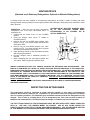
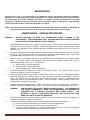
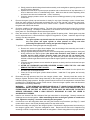
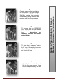
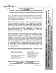
All fire extinguishers should be installed, inspected and maintained in accordance with the National Fire Protection Association standard titled "Portable Fire Extinguishers", NFPA-10 and the requirements of local authorities having jurisdiction. When maintenance is indicated it should be performed by trained persons having proper equipment. Fire extinguishers are pressure vessels and must be treated with respect and handled with care. They are mechanical devices and require periodic maintenance to be sure that they are ready to operate properly and safely. Amerex strongly recommends that the maintenance of portable fire extinguishers be done by a trained professional – your local authorized Amerex Distributor. Amerex Corporation makes original factory parts available to insure proper maintenance – USE OF SUBSTITUTE PARTS RELEASES AMEREX OF ITS WARRANTY OBLIGATIONS. Amerex parts have machined surfaces and threads that are manufactured to exacting tolerances. O-rings, hoses, nozzles, and all metal parts meet precise specifications and are subjected to multiple in-house inspections and tests for acceptability. There are substitute parts available that may be incorrectly labeled as UL component parts, some are advertised as Amerex type. None of these meet UL requirements and all of them void the Amerex extinguisher warranty and UL listing. DO NOT SUBSTITUTE. RECHARGE FIRE EXTINGUISHERS IMMEDIATELY AFTER ANY USE REFERENCES IN THIS MANUAL: NFPA-10 Portable Fire Extinguishers AVAILABLE FROM: National Fire Protection Association 1 Batterymarch Park, P.O, Box 9101 Quincy, MA 02269-9101 CGA C-1 Methods for Hydrostatic Testing of Compressed Gas Cylinders CGA C-6 Standard for Visual Inspection of Compressed Gas Cylinders Compressed Gas Association, Inc. 4221 Walney Road, 5th Floor Chantilly, VA 20151-2923 AMEREX CORPORATION – P.O. BOX 81 – TRUSSVILLE, ALABAMA 35173-0081 Phone: 205/655-3271 Fax: 800/654-5980 e-mail: [email protected] Web Page: http://www.amerex-fire.com Printed in U.S.A. 0M05615D Rev. 4/09 MODEL 630 WHEELED / MODEL 631 STATIONARY 33 GALLON (FFFP) ALCOHOL RESISTANT FOAM FIRE EXTINGUISHER 23 CU FT NITROGEN CYLINDER OPERATED OWNERS SERVICE MANUAL NO. 05615 INSTALLATION, OPERATING & SERVICING INSTRUCTIONS INTRODUCTION Amerex Model 630 33 gal. Wheeled and Model 631 Stationary FFFP Foam fire extinguisher provides large volume Class A and Class B firefighting capability. The Model 630 can be transported and operated by one person and the Model 631 fits easily into a pick-up truck. The alcohol resistant Angus "ALCOSEAL" FFFP foam charge makes it particularly effective on fires and spills involving hydrocarbons, alcohols, esters, ketones and gasohols. The "nitrogen cylinder operated" design features a unique stainless steel agent storage cylinder which requires no interior coating to prevent corrosion. The agent cylinder is connected to a high pressure nitrogen cylinder through quick opening "T" handle type valve. Field recharging is possible but to provide optimum extinguisher reliability, recharging should be performed by persons trained in fire extinguisher maintenance and servicing. This manual should be used as a guide for installing, operating and servicing this extinguisher. The best place to have your extinguisher serviced and recharged is your "Authorized Amerex Distributor" who has the professional experience and equipment to do it properly. THIS MANUAL IS ATTACHED TO EVERY NEW EXTINGUISHER SHIPPED FROM THE FACTORY. IT CONTAINS VALUABLE INFORMATION WHICH SHOULD BE STUDIED BY EVERYONE WHO WILL USE OR SERVICE THE EXTINGUISHER. THE MANUAL SHOULD BE STORED IN A CONVENIENT LOCATION FOR EASY REFERENCE. PREPARING YOUR NEW EXTINGUISHER WARNING: THIS FIRE EXTINGUISHER IS SHIPPED FROM THE FACTORY EMPTY. AFTER INITIAL PREPARATIONS, CAREFULLY FOLLOW THE RECHARGING INSTRUCTIONS BEFORE PLACING IT INTO SERVICE. 1. Remove all wrappings, straps and pallet retaining bolts. 2. Examine the extinguisher for shipping damage. Check to make sure that you have received the Model 534 2 gal. FFFP foam concentrate charge which is packaged with the extinguisher. 3. Fill the extinguisher by carefully following the Recharge instructions (Page 6). 4. Remove the nitrogen cylinder protective shipping cap. Save the cap as it must be installed whenever a charged nitrogen cylinder is transported. Remove temporary (shipping) ring pin and install large ring pin. 5. Install new lockwire seal. Check the nitrogen cylinder pressure. The gauge should read approximately 2015 psig (13.9 mPa) at 70ºF (21ºC) ambient temperature. See the "Troubleshooting Guide" for pressure-temperature allowances. The lockwire seal should be intact. 6. Remove (and save) the Safety Vent Plug installed on all "T" handle nitrogen valves. Connect the nitrogen supply hose firmly to the nitrogen cylinder valve. Make sure that there are no kinks in this hose. 7. Disconnect the discharge hose assembly from the agent cylinder. Make sure that the hose and nozzle are unobstructed and that the P/N 07411 Moisture Seal is undamaged and properly seated on the agent cylinder discharge fitting. Reconnect the discharge hose to the agent cylinder and with the nozzle in the closed (forward) position, place it on the storage rack. (See Page 8) 8. Record the date the unit is being placed into service on the inspection tag and attach it to the extinguisher. 9. Remove the caution (not charged) tag. Manual 05615 Rev. D Page 1 INSTALLATION Do not place this extinguisher close to a potential fire hazard. Amerex recommends location no less than a 50 foot distance from the hazard while leaving an unobstructed access. Avoid placing it in an extremely hot or cold place. The operational temperature range for this ex t in g uis h er is +35°F to +120°F (+2°C to +49°C). The extinguisher should be adequately protected if temperatures outside of this range are anticipated. Keep the extinguisher clean and free from dirt, ice, chemicals and any contaminants that may interfere with its proper operation. DO NOT FUNCTIONALLY TEST THIS FIRE EXTINGUISHER. (Testing or any use may cause the extinguisher to gradually lose extinguishing agent over a period of time and make the extinguisher ineffective.) WARNING: The models 630 and 631 alcohol resistant FFFP foam fire extinguishers have been tested and listed for Class A & B fires only. DO NOT USE ON CLASS C FIRES INVOLVING ENERGIZED ELECTRICAL EQUIPMENT, CLASS D FIRES OR ANY FLAMMABLES THAT WILL REACT WITH WATER. WARNING: These extinguishers must be located in an area in which they will be protected from freezing. THERE ARE NO KNOWN ANTI-FREEZE ADDITIVES WHICH WILL PROTECT THESE UNITS FROM FREEZING without adversely affecting the foam fire fighting effectiveness. In some cases, a properly sized barrel heater may afford adequate protection. OPERATION NOTE: Persons expected to use this extinguisher should be trained in initiating its operation and in the proper fire fighting technique. Familiarize all personnel with this information before an emergency occurs. 1. Move the extinguisher to within approximately 50 feet of the fire site and remove ring (safety) pin. Pull "T" handle to open nitrogen valve. This will pressurize the extinguisher. 2. Remove nozzle from the mount, and with the nozzle lever in the closed position, pull hose from rack. 3. Start back 30 feet from the fire and aim at base of fire nearest you. 4. Hold hose and nozzle firmly and be prepared for discharge recoil. Open nozzle by pulling the handle toward you. Slowly sweep side to side across the base of the fire and past both edges. Progressively follow up until the fire is extinguished. Note: Do not cover the nozzle aspirating holes when discharging this extinguisher. Discharge Time (approx.): Effective Range of the agent throw is: Hose Length: 60 seconds 35 – 40 feet 50 feet RECHARGE FIRE EXTINGUISHERS IMMEDIATELY AFTER ANY USE SHUTDOWN 1. After making sure that the fire has been completely extinguished, expel all remaining extinguishing agent and pressure, then push the nozzle lever forward to the closed position. Close the nitrogen valve (PUSH "T" HANDLE TO CLOSED POSITION). 2. When the hose is empty, push the nozzle lever to the CLOSED position. 3. Slowly open the nozzle lever again to insure that the extinguisher and hose have been completely cleared of agent and pressure. 4. Coil the extinguisher hose onto the storage rack and position the nozzle onto the mount in preparation for transport to the recharge location. CAUTION: Manual 05615 Rev. D DO NOT TRANSPORT A NITROGEN CYLINDER WITH ANY REMAINING PRESSURE WITHOUT INSTALLING THE PROTECTIVE SHIPPING CAP. Page 2 VENTING DEVICE (Standard on all Stationary Extinguishes, Optional on Wheeled Extinguishers) A venting device has been installed on all stationary extinguishers to provide a means of safely and easily relieving residual nitrogen pressure from the agent cylinder while utilizing the same pressure to evacuate or "blow down" the hose. OPERATION – After the fire has been successfully extinguished and it has been determined that it is completely out: 1. Confirm that the nozzle lever is in the CLOSED position. 2. Close the nitrogen valve (move "T" handle to CLOSED position) 3. Remove ring pin and CLOSE agent cylinder valve (Valve A in Fig. 1) to prevent further chemical from entering the hose. 4. Remove ring pin and OPEN pressure vent valve (Valve B in Fig. 1) to allow nitrogen gas to by-pass the chemical and pressurize the hose. 5. Open discharge nozzle to vent all residual chemical and nitrogen gas pressure. 6. Re-open nitrogen valve if additional pressure is required. 7. When recharging this unit, reset agent cylinder and vent valves, install ring pins and lockwire seals. CAUTION:VALVE SHUT-OFF HANDLES MUST BE IN THE POSITIONS SHOWN WHEN EXTINGUISHER IS ON STANDBY OR IN ACTUAL OPERATION. AMEREX CORPORATION DOES NOT SERVICE, MAINTAIN OR RECHARGE FIRE EXTINGUISHERS. THIS MANUAL IS PUBLISHED AS A GUIDE TO ASSIST QUALIFIED SERVICE PERSONNEL IN THE INSPECTION, MAINTENANCE AND RECHARGE OF AMEREX FIRE EXTINGUISHERS ONLY. NO INSTRUCTION MANUAL CAN ANTICIPATE ALL POSSIBLE MALFUNCTIONS THAT MAY BE ENCOUNTERED IN THE SERVICE OF FIRE EXTINGUISHERS. DUE TO THE POSSIBILITY THAT PRIOR SERVICE PERFORMED ON THIS EQUIPMENT MAY HAVE BEEN IMPROPERLY DONE, IT IS EXTREMELY IMPORTANT THAT ALL WARNINGS, CAUTIONS AND NOTES IN THIS MANUAL BE CAREFULLY OBSERVED. FAILURE TO HEED THESE INSTRUCTIONS COULD RESULT IN SERIOUS INJURY. AMEREX ASSUMES NO LIABILITY FOR SERVICE, MAINTENANCE OR RECHARGE OF FIRE EXTINGUISHERS BY PUBLISHING THIS MANUAL. INSPECTING THE EXTINGUISHER This extinguisher should be inspected at regular intervals (monthly or more often if circumstances dictate) to insure that it is ready for use. Inspection is a "quick check" that a fire extinguisher is available and is in operating condition. It is intended to give reasonable assurance that the fire extinguisher is fully charged. This is done by verifying that it is in its designated place, that it has not been actuated or tampered with, and that there is no obvious physical damage or condition to prevent its operation. THE FFFP FOAM CHARGE IN THIS EXTINGUISHER MUST BE REPLACED EVERY THREE YEARS PER NFPA 10. USE ONLY THE AMEREX MODEL 534 CHARGE. USE OF ANY OTHER AGENTS OR SUBSTITUTES WILL VOID THE UL LISTING AND AMEREX WARRANTY. SEE THE RECHARGE SECTION OF THIS MANUAL FOR THE APPROPRIATE EMPTYING AND RECHARGING INSTRUCTIONS. Manual 05615 Rev. D Page 3 MAINTENANCE At least once a year or more frequently if circumstances require, maintenance should be performed. Maintenance is a "thorough check" of the extinguisher. It is intended to give maximum assurance that a fire extinguisher will operate effectively and safely. It includes a thorough examination for physical damage or condition to prevent its operation and any necessary repair or replacement. It will normally reveal if hydrostatic testing or internal maintenance is required. NOTE: The Getz Manufacturing Universal Wheeled Extinguisher Service Kit is available so that NFPA-10 required maintenance functions can be performed. Getz part numbers are referenced. MAINTENANCE – SERVICE PROCEDURE WARNING: BEFORE SERVICING BE SURE THE EXTINGUISHER AGENT CYLINDER IS NOT PRESSURIZED. THIS PROCEDURE IS BEST ACCOMPLISHED WITH THE EXTINGUISHER IN AN UPRIGHT POSITION AND ON A LEVEL SURFACE. 1. Clean extinguisher to remove dirt, grease or foreign material. Check to make sure that the instruction nameplate is securely fastened and legible. Inspect the cylinders for corrosion, abrasion, dents or weld damage. If any damage is found, hydrostatically test in accordance with instructions in CGA C-1 and C-6 and NFPA 10. 2. Inspect the extinguisher for damaged, missing or substitute parts. A careful inspection should be made of the safety relief to make sure that it has not ruptured, corroded or been tampered with. Only factory replacement parts are approved for use on Amerex fire extinguishers. 3. Check the date of manufacture printed on the extinguisher label (nameplate) or on the agent cylinder dome. The agent cylinder, the discharge hose assembly and nitrogen supply hose must be hydrostatically tested every 5 years. Test pressure: a. Agent Cylinder – 450 psi (3103 kPa) b. Hose Assembly – 300 psi (2068 kPa) c. Nitrogen Supply Hose – 3000 psi (20,628 kPa) 4. Check the hydrostatic test date on the crown of the nitrogen cylinder. The nitrogen cylinder must be retested in accordance with DOT regulations. 5. Check the gauge on the nitrogen cylinder. If the pressure is below 1700 psig (11.7 mPa) repressurize the cylinder to 2015 psig (13.9 mPa) or replace it. A low gauge pressure may indicate leakage. Check for leaks. A low gauge reading may also result from low temperature. See the temperature/pressure relationship chart in the Troubleshooting Guide. Check the tamper indicator (lockwire seal) on the nitrogen valve and replace if necessary. 6. Wheeled extinguishers (Model 630) – Inspect the wheels to insure they rotate freely. Lubricate as required. Stationary extinguishers (Model 631) – Check to insure that any mounting fixtures are secure. 7. WARNING: ALWAYS OPEN THE SHUTOFF NOZZLE HANDLE SLOWLY. ANY PRESSURE IN THE AGENT CYLINDER WILL CAUSE THE EXTINGUISHER TO DISCHARGE. BE PREPARED FOR A POSSIBLE DISCHARGE AND NOZZLE RECOIL. ANY EVIDENCE OF AGENT IN THE NOZZLE INDICATES THAT THE UNIT MAY HAVE BEEN USED AND THE USE NOT REPORTED. Disconnect the discharge hose from the agent cylinder. Check the couplings, hose and hose gaskets for damage or deterioration – replace as necessary. 8. To perform an operational integrity check on the discharge hose and nozzle combination: a. Connect the test kit hose adapter to the female end of the discharge hose. b. Close the discharge nozzle shut-off lever and properly secure it. c. Connect a properly regulated and verified nitrogen pressure source, set to the extinguisher operating pressure (235-245 psi) to the test kit hose adapter. Manual 05615 Rev. D Page 4 d. Slowly pressurize the discharge hose/nozzle assembly to the extinguisher operating pressure and check for leaks or distortion. e. Operate the nozzle lever to ensure proper operation and to clear the hose of any obstructions. If hose is obstructed refer to Troubleshooting Guide. Make sure that the nozzle aspirating holes and screen are clear and unobstructed – clean if necessary. f. Close the nitrogen pressure source and slowly relieve remaining pressure by fully operating the nozzle lever. 9. Remove the agent cylinder cap and examine it closely for any signs of damage, cracks or thread wear. Clean the agent cylinder fill cap threads and thread vent port on the cap with a stiff bristle nylon brush. Remove the fill cap gasket and check for wear, cracks or tears – replace if necessary. Lightly lubricate the gasket with Visilox and reinstall. 10. Check the condition of the chemical solution. The level of the solution should be 9 inches (23 cm) below the top of the fill opening. Recharge if contaminated, if the solution level is down or if the charge is over three years old. See Recharge instructions and procedures. 11. Place the service kit Vent Spacer on top of the agent cylinder fill opening collar. Check again to see that the fill cap thread vent is clean and that the agent fill cap gasket is in place. Install the agent fill cap securely over the vent spacer. 12. CAUTION: The agent cylinder cap threads must be clear and the cap securely installed onto the vent spacer and agent cylinder to allow pressure to slowly vent after performing the siphon tube clearing and gas tube integrity checks. To perform a siphon tube clearing and gas tube integrity check: a. Remove the service kit Agent Hose Adapter from the discharge hose assembly and install it securely onto the agent cylinder siphon tube outlet. b. Using a regulated nitrogen pressure source set to the extinguisher operating pressure, slowly and briefly pressurize the agent cylinder (the siphon tube should be clear within a couple of seconds and the agent cylinder pressure slowly vent from the fill cap thread vent). Pressure and/or foam agent leaks from the gas tube inlet port (where the hose connects) will indicate a defective gas tube and will require that the agent cylinder be emptied and the gas tube replaced. c. Close the nitrogen pressure source and allow all pressure to slowly vent from the thread vent port on the fill cap. d. AFTER ALL PRESSURE HAS BEEN RELIEVED, SLOWLY OPEN THE FILL CAP AND REMOVE THE TEST KIT VENT SPACER. e. Re-examine the foam agent to determine if any obstructions were cleared from the siphon tube and have risen to the liquid surface. f. Clean the fill cap and agent cylinder thread surfaces. Install the fill cap gasket and securely install fill cap. 13. Disconnect the high pressure hose from the nitrogen cylinder valve. Securely install the service kit Nitrogen Cylinder Pressure Check Gauge Assembly to the nitrogen cylinder valve outlet and verify the indicated cylinder gauge pressure. Nitrogen pressure should conform to the temperature correction chart provided in the Troubleshooting section of this manual. Close the nitrogen cylinder valve and disconnect the Pressure Check Gauge Assembly. WARNING: IF THE NITROGEN CYLINDER VALVE HAS A "T" HANDLE QUICK OPENING OR A HANDWHEEL QUICK OPENING TRIP RELEASE, THE SAFETY VENT PLUG SHIPPED WITH THE EXTINGUISHER, OR THE TEST KIT SAFETY VENT PLUG, MUST BE INSTALLED TO PROTECT SERVICE PERSONNEL FROM A HIGH VELOCITY DISCHARGE IN CASE THE LEVER IS ACCIDENTALLY OPENED. 14. Install a new Amerex P/N 07411 Moisture Seal per instructions in the package. Securely connect the discharge hose to the extinguisher. When assembling the hose to the agent cylinder or nozzle to the hose, tighten the coupling ¼ turn after contacting the hose gasket. 15. Coil the hose on to the extinguisher hose rack using the Reverse Loop Procedure (see Page 7). Install nozzle with the lever in the Closed (forward) position into the nozzle mount. 16. Remove the safety vent plug from the nitrogen cylinder. Reconnect the high pressure hose securely to the nitrogen cylinder valve. Wipe the extinguisher clean. Record service data on the inspection tag according to NFPA-10 requirements and attach to extinguisher. Return extinguisher to its proper location. Manual 05615 Rev. D Page 5 RECHARGE CAUTION: THE FIRE EXTINGUISHING AGENT IN THIS EXTINGUISHER MUST BE COMPLETELY REPLACED EVERY THREE YEARS. WARNING: BEFORE ATTEMPTING TO RECHARGE BE SURE THIS EXTINGUISHER IS COMPLETELY DEPRESSURIZED. THERE IS A CHECK VALVE IN THE SYSTEM WHICH PREVENTS NITROGEN PRESSURE FROM ESCAPING FROM THE AGENT CYLINDER WHEN THE NITROGEN HOSE IS DISCONNECTED. THE AGENT CYLINDER MAY BE PRESSURIZED EVEN THOUGH NO PRESSURE ESCAPES FROM THE CYLINDER NITROGEN CONNECTION. RECHARGING PROCEDURE 1. To depressurize: a. Close the nitrogen valve. b. Open the nozzle lever slowly to discharge all remaining agent and pressure (be prepared for nozzle recoil). c. Insure that all pressure has escaped before further disassembly. 2. Carefully remove the fill cap. Thoroughly rinse the complete interior of the agent cylinder with clean water. Dump or siphon all liquid from the cylinder. Detach discharge hose from the agent cylinder and the nozzle assembly from the hose. Remove the ruptured moisture seal from the female hose coupling and flush the hose and nozzle assemblies with clean water. 3. Perform Maintenance-Service Procedures 1 through 6. 4. Detach the hose from the nitrogen cylinder, install the shipping cap, unscrew the wing nuts and remove the nitrogen cylinder from the extinguisher. 5. Fill the agent cylinder with 28 gallons of clean, fresh water (to a level just touching the bottom of the internal nitrogen tube). Pour three (3) gallons of clean, fresh water into an Amerex 2 gallon Model 534 FFFP charge. (NOTE: Charge contains 2 gallons of concentrate in a 5 gallon pail.) Carefully stir until you have a complete and homogeneous mixture. Slowly pour the solution into the agent cylinder. The liquid level in the extinguisher cylinder should now be 9 inches (23 cm) from the top of the fill opening. Clean, lubricate and install (or replace if necessary) the fill cap gasket. Install the fill cap and tighten securely. Rock the extinguisher back and forth for two minutes to accomplish a more thorough agent mix. WARNING: DO NOT OVERFILL THE EXTINGUISHER. THIS COULD CAUSE A MALFUNCTION OR PREMATURE RUPTURE OF THE SAFETY DISC. 6. Install an Amerex P/N 03817 23 cu. Ft. nitrogen cylinder (pressurized to 2015 psi). Remove the shipping cap, tighten the wing nuts securely and attach the nitrogen hose. NOTE: NITROGEN CYLINDERS WITH A "T" HANDLE "QUICK OPENING" VALVE. REMOVE SMALL TEMPORARY RING (SAFETY) PIN AND INSTALL A LARGE RING PIN. INSTALL A LOCKWIRE SEAL (TAMPER INDICATOR.) NITROGEN CYLINDERS WITH A HANDWHEEL OR LEVER ACTUATED "QUICK OPENING" VALVE. A LEADWIRE SEAL MUST BE INSTALLED. 7. Remove the remainder of the ruptured moisture seal from the agent cylinder fitting. Replace with a new P/N 07411 Moisture Seal Assembly. Carefully follow the installation instructions contained in the P/N 07411 package including the installation of a new clear hose gasket in the female house coupling. 8. Reattach the hose to the extinguisher (tighten hand tight plus a ¼ turn). Properly coil the hose onto the storage rack ring leverage loop. Reattach the shutoff nozzle firmly to the hose and store it in the mount with the shutoff lever in the closed (forward) position. 9. Record the service date on the inspection tag and place the extinguisher in its proper location. Manual 05615 Rev. D Page 6 TROUBLESHOOTING GUIDE WARNING: BEFORE ATTEMPTING TO CORRECT ANY LEAKAGE PROBLEM, BE SURE THAT THE CYLINDER AND HOSE ARE COMPLETELY EMPTY AND DEPRESSURIZED. Check to determine the source of a leak before the extinguisher is emptied. Leakage repairs will require depressurization and removal of the valve assembly. Use Getz HR-1 or other "APPROVED" recharge/recovery system to depressurize extinguisher. PROBLEM 1. Nitrogen cylinder gauge reads low or high CORRECTIVE ACTION Temperature may have affected the pressure reading Temperature (F) 35º 70º 120º Temperature (C) 2º 21º 49º Recommended Pressure psig 1880 2015 2200 mPa 13.0 13.9 15.2 Minimum Pressure psig 1590 1700 1900 mPa 11.0 11.7 13.1 NO CORRECTIVE ACTION IS REQUIRED IF THE PRESSURE IS WITHIN PARAMETERS STATED ABOVE. 2. Nitrogen pressure is too low. Valve is closed. Tamper seal is intact. There is pressure in the agent and nitrogen cylinders. Valve seat has leaked and has pressurized the agent cylinder. Follow Recharge Procedure for restoring the extinguisher to service. 3. Nitrogen pressure is too low. Valve is closed. Tamper seal is intact. No pressure observed in the agent cylinder. Leakage in the nitrogen valve at other than the valve seal. Replace with a properly charged nitrogen cylinder. 4. Shutoff nozzle does not move freely. Disassemble, clean and lubricate. 5. Unable to remove the agent cylinder cap. Agent cylinder may be pressurized. Make no further attempt to remove the cap until this is checked. See the Recharge Procedure for proper depressurization method. 6. Nitrogen hose cut, cracked or abraded. Replace hose assembly with P/N 02234. 7. Chemical agent and pressure leaking from the safety disc assembly. Inspect safety outlet for tightness or damage. necessary. Manual 05615 Rev. D Tighten if NOTE: Only tighten the large hex nut of the assembly. The small round nut containing the holes is factory set to a specific torque value. Do not attempt to adjust. If damaged or ruptured, replace complete Amerex P/N 03787 safety disc assembly. Page 7 2 The second loop is a REVERSE loop. Notice that the hose passes behind the loop on this reverse loop. If instructions are followed, the hose will uncoil without kinks. 3 The next loop is a regular "hose in front" loop. Succeeding loops are alternated: reverse, front, reverse, etc. for six full loops. Guide to Proper Installation of Hose on Wheeled or Stationary Fire Extinguishers 1 Connect hose coupling to outlet on the extinguisher. Lay hose straight on ground to its full 50 ft. length. Start first regular loop counterclockwise by placing between side brackets and over the top bracket. 4 Adjust the loops so that the nozzle fits into the nozzle mount. Loops should be approximately the same size. Manual 05615 Rev. D Page 8 PARTS LIST for 33 Gal. FFFP Foam 23 Cu. Ft. Nitrogen Cylinder Wheeled/Stationary Extinguisher Models 630 631 tem No. 1 1A 2 3 3A 4 4A 5 6 7 7A 7B 7C 7D 7E 7F 8 9 10 11 12 13 14 15 16 17 18 19 Part No. 06993 Description Cap, Agent Cylinder Cap, Agent Cylinder 12576 w/Pressure Indicator 02272 Gasket, Cap 03787 Safety Disc Assembly – 630 07665 Safety Disc Assembly – 631 13956 Protective Vinyl Cap 07292 Nitrogen Hose Assembly 06883 Nitrogen Tube Assembly 06784 Downtube Assembly 13958 Bumper, Rubber 01387 Lock Wire Seal (Yellow) Nitrogen Valve w/Gauge 12467 ("T" handle Quick Release Safety Disc, Gasket & Nut 16516 Assembly Valve Lever ("T" Handle – 06373 Complete) 10213 Gauge – 3000 psi 09897 Valve Stem Assembly 12466 Spring 09627 Retainer Nitrogen Cylinder (23 cu ft.) – 03817 Charged, w/Cap Retaining Strap – Nitrogen 04072 Cylinder 11970 Bolt, Washer and Wing Nut 07479 Pictogram – 630, 631 Wheel Assembly 36" x 6" 07026 (Red) Wheel Assembly 36" x 6" 07607 w/Rubber Tread Hub Cap w/Washer and Cotter 07389 Pin 06814 Hose Assembly – 50 ft. 07411 Moisture Seal 03877 Gasket, Hose and Nozzle 06279 Ball Valve Assembly 06749 Nozzle Tip (Aerated) Nozzle Assembly (Ball Valve & 07560 Tip) PART NOT PICTURED Std. Pkg. 1 1 1 1 1 1 1 1 1 500 1 1 1 1 6 6 1 1 1 1 1 1 1 1 1 1 6 1 1 1 ALL HYDROTEST ADAPTERS – SEE ADAPTERS PAGE Manual 05615 Rev. D Page 9