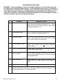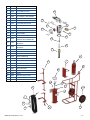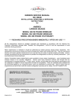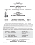
1
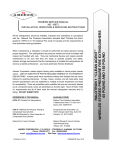
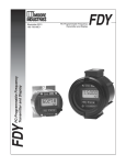
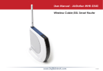
 When maintenance is indicated, it should be performed by trained persons having proper equipment. Fire extinguishers are pressure vessels and must be
treated with respect and handled with care. They are mechanical devices and
require periodic maintenance to be sure that they are ready to operate properly
and safely. Amerex strongly recommends that the maintenance of portable fire
extinguishers be done by a trained professional – your local authorized Amerex
Distributor.
Amerex Corporation makes original factory parts available to insure proper
maintenance – USE OF SUBSTITUTE PARTS RELEASES AMEREX OF ITS
WARRANTY OBLIGATIONS. Amerex parts have machined surfaces and
threads that are manufactured to exacting tolerances. O-rings, hoses, nozzles,
and all metal parts meet precise specifications and are subjected to multiple inhouse inspections and tests for acceptability. There are substitute parts available that may be incorrectly labeled as UL component parts, some are advertised
as Amerex type. None of these meet UL requirements and all of them voids the
Amerex extinguisher warranty and UL listing. DO NOT SUBSTITUTE.
RECHARGE FIRE EXTINGUISHERS IMMEDIATELY AFTER ANY USE
REFERENCES IN THIS MANUAL:
AVAILABLE FROM:
NFPA-10 Portable Fire Extinguishers
National Fire Protection Association
1 Batterymarch Park, P.O, Box 9101
Quincy, MA 02269-9101
CGA C-1 Methods for Hydrostatic Testing of
Compressed Gas Association, Inc.
Compressed Gas Cylinders
4221 Walney Road, 5th Floor
CGA C-6 Standard for Visual Inspection of
Chantilly, VA 20151-2923
PURPLE K (POTASSIUM BICARBONATE BASE)
All fire extinguishers should be installed, inspected and maintained in accordance with the National Fire Protection Association standard titled "Portable Fire
Extinguishers", NFPA-10 and the requirements of local authorities having jurisdiction.
MODEL 688 STORED PRESSURE, WHEELED
50 POUND DRY CHEMICAL FIRE EXTINGUISHER
OWNERS SERVICE MANUAL NO. 22241
INSTALLATION, OPERATING & SERVICING INSTRUCTIONS Compressed Gas Cylinders
AMEREX CORPORATION – P.O. BOX 81 – TRUSSVILLE, ALABAMA 35173-0081
Phone: 205/655-3271
e-mail: [email protected]
Fax: 800/654-5980
Web Page: http://www.amerex-fire.com
PRINTED IN USA MANUAL 22241 REV D 9‐5‐14 1
THIS MANUAL IS ATTACHED TO EVERY NEW EXTINGUISHER SHIPPED FROM THE FACTORY. IT CONTAINS
VALUABLE INFORMATION WHICH SHOULD BE STUDIED BY EVERYONE WHO WILL USE OR SERVICE THE
EXTINGUISHER. THE ANUAL SHOULD BE STORED IN A CONVENIENT LOCATION FOR EASY REFERENCE.
INTRODUCTION
The Amerex Models 688 Stored Pressure Wheeled Dry Chemical fire extinguishers designed to
provide larger volumes of dry chemical fire fighting agent than hand portable types for industrial applications. The wheeled version can easily be transported and operated by one person and in a
stationary configuration and can be mounted in a small space. The cage type carriage provides
protection for the operating valve, cylinder and hose assembly. Easy rolling 16 inch semipneumatic rubber tires assure minimum effort to quickly transport them through narrow spaces to a
fire scene.
Maximum protection from severe corrosive environment is afforded by the Amerex corrosion resistant metal preparation and paint finish. The operating valve, handle, gauge guard, fill cap, house
couplings and ball type shutoff are brass, or brass chrome plated for years of trouble free use.
These models carry an Amerex warranty of six years – see full wording of the warranty below.
Field recharging is possible utilizing maintenance/recharge equipment available through your
Amerex Distributor. To provide optimum extinguisher reliability, recharging should be performed by
persons trained in fire extinguisher maintenance and servicing. This manual should be used as a
guide for installing, operating and servicing this extinguisher. The best place to have your extinguisher serviced and recharged is your Authorized Amerex Distributor who has the professional experience and equipment to do it properly.
NOTE: THIS MANUAL INCLUDES SERVICE INFORMATION FOR DRY CHEMICAL EXTINGUISHERS ONLY. SEE MANUAL 05603 FOR MAINTENANCE AND SERVICE INSTRUCTIONS
FOR CARBON DIOXIDE EXTINGUISHERS.
SIX YEAR LIMITED WARRANTY
Amerex warrants its fire extinguishers to be free from defects in material and workmanship for a period of six (6) years from the date of purchase. During the warranty period, any such defects will be
repaired or the defective extinguisher replaced if only factory replacement parts and recommended
service equipment have been used to service the extinguisher. This warranty does not cover defects resulting from modification, alteration, misuse, exposure to unusually corrosive conditions nor
improper installation or maintenance. All implied warranties, including, but not limited to, warranties
of fitness for purpose and merchantability, are limited to the timer periods as stated above. In no
event shall Amerex Corp. be liable for incidental or consequential damages. Some states do not
allow limitations on how long an implied warranty lasts or the exclusion or limitation of incidental or
consequential damages, so that the above limitations or exclusions may not apply to you. Amerex
Corp. neither assumes nor authorizes any representative or other person to assume for it any obligation or liability other than expressly set forth herein. This warranty gives you specific legal rights,
and you may also have other rights which may vary from state to state. To obtain performance of
the obligation of this warranty, write to Amerex Corp., P. O. Box 81, Trussville, AL 35173-0081 for
instructions.
MANUAL 22241 REV D 9‐5‐14 2
AMEREX CORPORATION DOES NOT SERVICE, MAINTAIN OR RECHARGE FIRE EXTINGUISHERS.
THIS MANUAL IS PUBLISHED AS A GUIDE TO ASSIST QUALIFIED SERVICE PERSONNEL IN THE
INSPECTION, MAINTENANCE AND RECHARGE OF AMEREX FIRE EXTINGUISHERS ONLY. NO INSTRUCTION MANUAL CAN ANTICIPATE ALL POSSIBLE MALFUNCTIONS THAT MAY BE ENCOUNTERED IN THE SERVICE OF FIRE EXTINGUISHERS. DUE TO THE POSSIBILITY THAT PRIOR SERVICE PERFORMED ON THIS EQUIPMENT MAY HAVE BEEN IMPROPERLY DONE, IT IS EXTREMELY
IMPORTANT THAT ALL WARNINGS, CAUTIONS AND NOTES IN THIS MANUAL BE CAREFULLY OBSERVED. FAILURE TO HEED THESE INSTRUCTIONS COULD RESULT IN SERIOUS INJURY.
AMEREX ASSUMES NO LIABILITY FOR SERVICE, MAINTENANCE OR RECHARGE OF FIRE EXTINGUISHERS BY PUBLISHING THIS MANUAL.
PREPARING YOUR NEW EXTINGUISHER FOR USE
1. Examine the extinguisher for evidence of shipping damage. Notify the delivering carrier immediately if any damage is discovered.
2. Remove all wrappings, straps and pallet retaining bolts.
3. Check to insure that the hose connection to the operating valve and shut-off nozzle to the hose are
tight.
4. Check to insure that the shut-off nozzle is in the closed position. The ring (safety) pin should be installed in the operating valve and the lockwire (tamper) seal intact.
5. Check to make sure that the cap is on the "bleeder valve" (located on the side of the extinguisher
operating valve). The pressure seal is in the cap and it must be in place to prevent leakage.
6. This extinguisher is shipped from the factory fully charged. Visually inspect the pressure gauge –
the pressure should be in the green zone (240 psi ± approx. 10 psi range). The most accurate method
to determine if the extinguisher is filled with the proper amount of chemical is to weigh the unit. The
gross weight is indicated on the nameplate (label).
NOTE:
Slight pressure variances in the gauge reading may be found if the
extinguisher has been subjected to extremes of heat or cold. High
temperatures can cause high gauge readings and low temperatures,
low readings. When in doubt, condition the extinguisher to 70ºF
(21ºC) for several hours to obtain more accurate pressure gauge
readings.
7. Record the date the unit is being placed into service on the inspection tag and attach it to the extinguisher.
INSTALLATION
Do not place this extinguisher close to a potential fire hazard. Amerex recommends location no
less than a 50 foot distance from the hazard while leaving an unobstructed access. Avoid placing it
in an extremely hot or cold place. The operational temperature range for this extinguisher is -65º to
+120ºF (-54º to +49ºC). The extinguisher should be adequately protected if temperatures outside
of this range are anticipated. Keep the extinguisher clean and free from dirt, ice, chemicals and any
contaminants which may interfere with its proper operation. Do not functionally test this fire extinguisher. (Testing or any use may cause the extinguisher to gradually lose pressure and become
ineffective.)
MANUAL 22241 REV D 9‐5‐14 3
OPERATION
NOTE:
Persons expected to use this extinguisher should be trained in initiating its
operation and in the proper firefighting technique. Familiarize all personnel
with this information before an emergency occurs.
1. Move the extinguisher to within approximately 50 feet of the fire site. Keep the extinguisher upright.
CAUTION:
This extinguisher must be operated in an upright position. If equipped
with an optional tow loop and vehicle towed to the fire scene, remove
from tow hitch and operate in a vertical position.
CAUTION:
Towing speeds in excess of 10 mph (16 km/h) will result in damage to
semi-pneumatic wheels. Damage caused by excessive towing speeds
is not covered under warranty.
2. Twist and pull ring pin. Open cylinder discharge valve by rotating (pulling) the handle valve lever toward the hose. The hose is now pressurized with chemical.
3. Pull nozzle, with lever in the closed position, from the mount and extend the hose from the storage
rack.
4. Stand back 30 feet from the fire and aim the nozzle at base of flames nearest you. Open nozzle by
pulling handle toward you (be prepared for a discharge recoil by holding the nozzle firmly).
5. Sweep side to side across the base of the fire and past both edges. Progressively follow up until the
fire is extinguished. Work the fire away from you while being alert for flashbacks. Move closer as the fire
is extinguished but not so close as to scatter or splash the burning materials.
6. When the fire is out, push the hose (discharge) lever forward to the closed position. Stand by and
watch for possible reignition.
7. Evacuate and ventilate the area immediately after extinguishing the fire. The fumes and smoke from
any fire may be hazardous and can be deadly.
DISCHARGE TIME – 688 – 30 Seconds (approximately)
EFFECTIVE RANGE OF AGENT THROW IS 25 TO 30 FEET
HOSE LENGTH – 25 FEET
MANUAL 22241 REV D 9‐5‐14 4
SHUTDOWN
CAUTION:
BEFORE PERFORMING THE SHUTDOWN PROCEDURE AND PREPARING
TO MOVE THE EXTINGUISHER TO THE RECHARGE LOCATION, DETERMINATION MUST BE MADE THAT THE FIRE IS COMPLETELY EXTINGUISHED AND THERE IS NO DANGER OF A FLASHBACK.
NOTE: These steps will allow easy depressurization of the extinguisher and clear the hose
assembly with a minimal loss of remaining chemical.
1. Tip the extinguisher to the horizontal position (resting on the carriage handle) and slowly rotate the
cylinder discharge valve lever to the open position. Slowly push the hose (discharge) nozzle lever to
the open position and be prepared for some chemical discharge.
2. When all pressure has been evacuated from the extinguisher, return the hose (discharge) nozzle
lever and cylinder discharge valve lever to the closed position.
3. Return the extinguisher to the upright position. Coil the hose onto the storage rack and position
the nozzle into the mount in preparation for transport to the recharge location.
RECHARGE EXTINGUISHERS IMMEDIATELY AFTER ANY USE
INSPECTING THE EXTINGUISHER
This extinguisher should be inspected at regular intervals (monthly or more often if circumstances dictate) to insure that it is ready for use. Inspection is a "quick check" that a fire extinguisher is available and is in operating condition. It is intended to give reasonable assurance that the fire extinguisher is fully charged. This is done by verifying that it is in its designated place, that it has not been actuated or tampered with, and that there is no obvious
physical damage or condition to prevent its operation.
PERIODIC INSPECTION PROCEDURES
(Monthly or more often if circumstances dictate)
[NFPA-10] Periodic inspection of fire extinguishers shall include a check of at least the following
items:
1.
2.
3.
4.
5.
6.
7.
8.
Location in designated place.
No obstruction to access or visibility.
Pressure gauge reading or indicator in the operable range or position.
Operating instructions on nameplate and facing outward.
Safety seals and tamper indicators not broken or missing.
Examination for obvious physical damage, corrosion, leakage, or clogged nozzle.
Determine fullness by weighing.
Wheels rotate freely.
MANUAL 22241 REV D 9‐5‐14 5
MAINTENANCE
[NFPA-10] At least once a year or more frequently if circumstances require, maintenance
should be performed. Maintenance is a "thorough check" of the extinguisher. It is intended
to give maximum assurance that a fire extinguisher will operate effectively and safely. It includes a thorough examination for physical damage or condition to prevent its operation and
any necessary repair or replacement. It will normally reveal if hydrostatic testing or internal
maintenance is required.
MAINTENANCE – SERVICE PROCEDURE
NOTE:
THIS PROCEDURE WILL BE BEST ACCOMPLISHED WITH THE EXTINGUISHER
IN AN UPRIGHT POSITION AND ON A LEVEL SURFACE.
1. Clean extinguisher to remove dirt, grease or foreign material. Check to make sure that the instruction nameplate is securely fastened and legible. Inspect the cylinders for corrosion, abrasion, dents or weld damage. If any damage is found, hydrostatically test to factory test pressure
500 psi (3448 kPa), using the proof pressure method, in accordance with instructions in C-6 and
NFPA 10. See proper method of depressurizing and reclaiming chemical in Recharge procedures. NOTE: WHEN CLEANING, AVOID USE OF SOLVENTS AROUND THE PRESSURE
GAUGE. THEY COULD SERIOUSLY DAMAGE THE PLASTIC GAUGE FACE.
2. Inspect the extinguisher for damaged, missing or substitute parts. Only factory replacement
parts are approved for use on Amerex fire extinguishers.
3. Weigh the extinguisher and compare with weight printed in the "Maintenance" section on the
nameplate (label). Recharge extinguisher if weight is not within indicated allowable tolerances.
4. Check the date of manufacture printed on the extinguisher label (nameplate) or on the agent cylinder dome. The agent cylinder must be hydrostatically tested in accordance with DOT requirements to the test pressure indicated on the nameplate.
5. Visually inspect the pressure gauge:
If bent, damaged or improper gauge, depressurize and replace.
If pressure is low, check for leaks.
6. Check ring pin for freedom of movement. Replace if bent, or if removal appears difficult.
7. Visually inspect, without removing, the agent fill plug for damage or distortion. Replace as necessary only after proper depressurization procedures have been performed (see complete
Maintenance – Six Year Teardown instructions).
MANUAL 22241 REV D 9‐5‐14 6
8. WARNING:
ALWAYS OPEN THE SHUTOFF NOZZLE HANDLE SLOWLY. ANY EVIDENCE OF AGENT IN THE NOZZLE INDICATES THAT THE UNIT MAY HAVE BEEN USED
AND THE USE NOT REPORTED. BE PREPARED FOR A POSSIBLE DISCHARGE AND
NOZZLE RECOIL. Check the nozzle shutoff lever for freedom of movement (open and close
several times). If the operation is impeded, disassemble the nozzle, replace parts and/or properly lubricate as necessary. Make sure that the nozzle tip is clear and unobstructed.
9. After making sure that there is no residual pressure in the discharge hose, disconnect it from the
operating valve. Blow air through the hose and nozzle assemblies to insure that the passage is
clear of foreign material. Check the couplings, hose and hose gasket for damage or deterioration
– replace as necessary.
10. Inspect the valve assembly for corrosion or damage to hose thread connection. Replace valve
assembly or component parts as necessary following the proper depressurization and recharge
procedures. If valve removal is necessary, complete all steps in the Complete Maintenance Procedure.
11. Reconnect the hose to the agent cylinder. Properly coil the hose on the rack and install the nozzle (with the lever in a closed position) on the mount. NOTE: WHEN ASSEMBLING THE HOSE
TO THE AGENT CYLINDER OR NOZZLE TO THE HOSE, TIGHTEN THE COUPLING ¼ TURN
AFTER CONTACTING THE HOSE GASKET.
12. Inspect the wheels on Models 688 to insure they rotate freely. Lubricate as required. On stationary models, check mountings to insure that they are securely fastened.
13. Check carriage assembly for loose nuts, bolts, frame distortion or damage. Check welds for
damage or corrosion. Replace damaged parts or make repairs as necessary.
14. Install new lockwire (tamper) seal and record service data on the extinguisher inspection tag.
15. If the extinguisher has been moved to perform service, make sure that it is returned to its proper
location.
MANUAL 22241 REV D 9‐5‐14 7
COMPLETE MAINTENANCE – SIX YEAR TEARDOWN
[NFPA-10] Every six years, stored pressure extinguishers that require a 12 year hydrostatic
test shall be emptied and subjected to the applicable maintenance procedures. When the applicable maintenance procedures are performed during periodic recharging or hydrostatic
testing, the six year requirement shall begin from that date.
NOTE: Some states have legislation which requires "Complete Maintenance" on an
annual basis. Please contact your local Amerex Distributor to see if these requirements apply to you. NFPA 10 recommendation requires that a "verification of service" external collar tag be installed on the extinguisher whenever a Six Year Maintenance is performed. The "verification of service" tag can only be installed if the operating valve has been removed.
1. Discharge chemical and pressure into a "closed" dry chemical recovery system (several are
commercially available). Make sure that the extinguisher is completely empty and depressurized. CAUTION:
These extinguishers operate at 240 psi. Some recovery systems
may require that the pressure be reduced to safely discharge the chemical and pressure into the system. Use the pressure bleeder valve on the extinguisher valve to reduce the pressure to a point registering just below the green operable area on the
pressure gauge. Discharge extinguisher into recovery system. Repressurize the extinguisher (to no more than 200 psi) to exhaust any chemical remaining in the extinguisher. NOTE: A "closed recovery system is designed to prevent loss of the chemical "fines" Loss of the "fines" could result in reduced extinguisher efficiency.
2. Clean extinguisher to remove dirt, grease or foreign material. Check to make sure that the
instruction nameplate is securely fastened and legible. Inspect the cylinder for corrosion,
abrasion, dents or weld damage. If any of these conditions are found and you doubt the integrity of the cylinder, hydrostatically test to factory test pressure marked on the nameplate
(label) in accordance with CGA C-1 and NFPA 10 and DOT regulations. NOTE: When
cleaning, avoid use of solvents around the pressure gauge. They could seriously
damage the plastic gauge face.
3. Inspect the extinguisher for damaged, missing or substitute parts. Only factory replacement
parts are approved for use on Amerex fire extinguishers.
4. Check the date of manufacture on the extinguisher dome. Cylinder must be hydrostatically
(proof pressure) tested every 12 years (first time), every 7 years thereafter, to the test pressure indicated on the nameplate (500 psi [3448 kPa]). Cylinder may be hydrostatically tested
every 12 years using the water jacket method.
5. Visually inspect the pressure gauge – if bent, damaged or improper gauge replace with the
proper Amerex pressure gauge (see Parts List).
6. Check ring pin for freedom of movement. Replace if bent or if removal appears difficult.
7. Verify that no pressure remains in the extinguisher. (Operating valve and nozzle shutoff
in open position and there is no discharge). Remove and inspect the agent fill cap for damage or distortion.
8. Check the nozzle shutoff lever for freedom of movement (open and close several times). If
the operation is impeded, disassemble the nozzle, replace parts and/or properly lubricate as
necessary. Make sure that the nozzle tip is clear and unobstructed.
9. Disconnect the discharge hose from the operating valve. Blow air through the hose and nozzle assemblies to insure that the passage is clear of foreign material. Check the couplings,
MANUAL 22241 REV D 9‐5‐14 8
hose and hose gasket for damage or deterioration – replace as necessary. The discharge
hose should be hydrostatically tested to 300 psi (2068 kPa) every twelve years.
10. Inspect the wheels to insure they rotate freely. Lubricate as required.
11. Check carriage assembly for loose nuts, bolts, frame distortion or damage. Check welds for
damage or corrosion. Replace damaged parts or make repairs as necessary.
12. WARNING: Valve removal and/or valve part replacement should be made only after
completing the depressurizing procedures listed in Step 1 of the Complete Maintenance section. Remove operating valve assembly. Inspect for corrosion or damage to
hose thread connection.
13. Complete steps 2 through 15 of Recharge Procedure.
RECHARGE
WARNING:
a. Before attempting to disassemble, be sure the extinguisher is completely depressurized.
b. Never have any part of your body over the extinguisher while removing the valve assembly.
c. Use a protective shield between you and the pressure gauge while charging an extinguisher. Do not stand in front of the gauge if a shield is not available.
d. Use a regulated pressurizing source of dry nitrogen only with a minimum dew point of minus 70ºF (minus 57ºC). Set the regulator to no more than 265 psi (1827 kPa).
e. Check and calibrate regulator gauge at frequent intervals. The regulator gauge should be
used to determine when the intended charging pressure has been reached. Do not use
the extinguisher gauge for this purpose.
f. Never leave an extinguisher connected to a regulator of a high pressure source for an extended period of time. A defective regulator could cause the cylinder to rupture due to excessive pressure.
g. Do not mix types of dry chemicals in extinguishers, recharge or recovery systems. Mixing
ABC (acidic base) with Regular, Purple-K, Super-K or Monnex (alkaline base) dry chemicals may result in a chemical reaction capable of developing a dangerous pressure
buildup.
RECHARGING PROCEDURE
1. Perform steps 1 through 12 of the "Complete Maintenance (Six Year Teardown)" section.
2. Thoroughly clean all parts of the disassembled valve with a soft bristle brush or soft cloth. Blow
the valve out with air or nitrogen. Inspect spring and downtube assembly, and replace parts if
worn or damaged. Install a new valve stem and collar o-ring after lightly lubricating with Bluestar
V-711 or equal (do not lubricate the valve stem seal).
3. Reassemble the valve assembly, including downtube and set aside.
MANUAL 22241 REV D 9‐5‐14 9
4. Remove any chemical remaining in the cylinder and check the condition. Properly dispose of
any chemical that is contaminated or caked.
5. Inspect the cylinder interior following CGA Visual Inspection Standard C-6.
6. Using an accurate scale, fill cylinder with the correct amount and type of dry chemical specified
on the label (nameplate). Use Amerex chemical which has been kept free of moisture and contamination. See Warning (g) – DO NOT MIX TYPES OF CHEMICALS.
7. Clean cylinder collar O-ring seat and collar threads with a small brush and then wipe off surfaces
with a clean cloth to remove dust. Lightly brush the collar O-ring seat with Bluestar V-711 (or
equal).
8. Install "verification of service" external collar tag. Install discharge valve assembly and attach
pressurizing adapter (P/N 09857) to discharge port.
9. With the extinguisher properly secured in an upright position, connect your nitrogen pressurizing
line with a quick connect to the nitrogen charging adapter. Rotate the extinguisher operating
valve lever to the open position and pressurize extinguisher with dry nitrogen to 240 psi. When
the desired pressure has been reached, rotate the operating lever to the closed position. Shut
off nitrogen supply and remove the quick connect. CAUTION: Pressurizing the extinguisher in
this manner will allow for proper aeration of the chemical through the downtube. Do not
use the "bleeder" valve to pressurize the extinguisher.
10. Check extinguisher for leaks by applying detecting fluid or a solution of soapy water to the nitrogen charging adapter orifice, around the collar o-ring sealing area, cylinder welds and gauge.
Remove the pressurizing adapter.
11. Reconnect the hose to the operating valve. Properly coil the hose on the rack and install the
nozzle (with the lever in a closed position) on the mount. NOTE: When assembling the hose to
the agent cylinder or nozzle to the hose, tighten the coupling ¼ turn after contacting the hose
gasket.
12. Install ring (safety) pin and lockwire (tamper) seal. Record recharge date and attach new recharge tag.
13. Weigh assembled extinguisher and confirm that the total weight is within the allowable tolerances
indicated in the Maintenance section of the nameplate (label).
14. Return extinguisher to its proper location. Mountings for stationary extinguishers should be
properly secured.
MANUAL 22241 REV D 9‐5‐14 10
TROUBLESHOOTING GUIDE
WARNING: Before attempting to correct any leakage problem, be sure that the agent cylinder and hose are completely depressurized. Check to determine the source of a leak before
the extinguisher is depressurized. Leakage repairs will require depressurization and removal
of the valve assembly. Depressurize by discharging into a Closed Recovery System or inverting the extinguisher. After depressurizing the extinguisher and correcting the problem, it
will be necessary to clean all valve parts thoroughly.
1. 2. 3. 4. 5. 6. 7. PROBLEM Leak at collar O-ring Leak at agent fill cap Leak through valve Leak at "bleeder" valve. Leak around gauge threads Defective gauge Leak in the cylinder CORRECTIVE ACTION Remove valve assembly, remove and discard O-ring,
clean collar and lube lightly with Bluestar V-711. Clean
O-ring groove on valve and install new collar O-ring.
Lubricate with Bluestar V-711. Remove cap, clean threads thoroughly and install new
O-ring. Lubricate O-ring with Bluestar V-711. Check valve stem seating area for scratches or foreign
matter. Clean seating area with a tooth brush and soft
cloth. Install new valve stem assembly. Remove and reinstall valve using Teflon tape on
threads. Note: "Bleeder" valve cap must be installed to
prevent leakage. Remove gauge*, clean threads and reinstall using Teflon tape on the gauge threads. Remove defective gauge* an install the proper Amerex
pressure gauge (P/N 05225 240 psi) using Teflon tape
on the gauge threads. Contact Amerex if under warranty, otherwise mark
"REJECTED" and remove from service or return to
owner. * Pressure gauge threads are coated with a special epoxy at the factory. For easy
removal, soak the valve assembly in hot water (180°F) for two to four minutes. Remove gauge with a thin 7/16" open end wrench. MANUAL 22241 REV D 9‐5‐14 11
ITEM PART# DESCRIPTION 1 2 06210 06279 NOZ WU ANOD.281 VLV ASY BALL WU 150 3 03877 GASKET HOSE 4 01387 SEAL TAMPER **NOT SHOWN 5 09806 6 07482 BKT ASY 811G CR RD PICTOGRAM 50 BC S‐PRS 7 21591 NPLATE 688 50.0 PK GOV 8 22230 FE 332.20.C02 USA GOV 9 22242 CYLINDER 50 LB PKP RED 10 22243 CARRIAGE ASSY RED 11 21592 HOSE SUPPORT 12 04945 13 21573 14 07751 15 10234 16 06059 HUB CAP BLACK DISCHARGE VALVE PKP COMPLETE WITH DOWNTUBE WHEEL ASSY HARDWARE: SEMI PNEUMATIC WHEEL ASSY WITH HARDWARE: PNEUMATIC VALVE LEVER WITH SCREWS 17 18 19 05225 06100 03562 GAUGE 240 PSI PULL PIN WITH WIRE GAUGE GUARD ASSY 20 00155 PRESSURE VALVE W/CAP 21 03678 VALVE BODY 22 06060 CAM WITH ORINGS 23 05239 COLLAR ORING 24 05067 VALVE STEM ASSY 25 26 27 28 04938 03556 10913 22974 DOWNTUBE ASSY SPRING HOSE ASSY 3/4 IN X 25 FT SUPPORT HOSE CYL 50 RD GOV 29 22543 TAPE REFLECTIVE PKP 16 18 17 21 22 19 20 23 24 26 25 8 5 11 10 29 6 13 9 14,15 27 7 2 3 28 1 MANUAL 22241 REV D 9‐5‐14 12 12