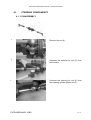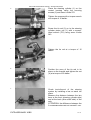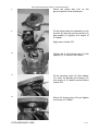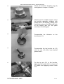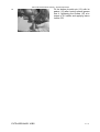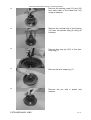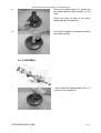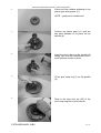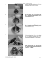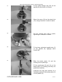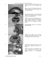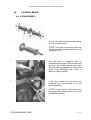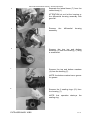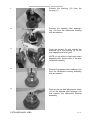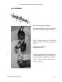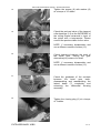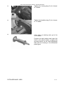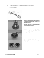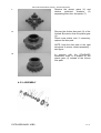
1
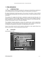
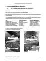
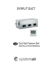
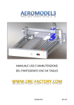
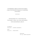
SERVICE MANUAL STEERING AND RIGID DRIVE AXLES SERIES 068 Date 06/10/09 Revision 1.0 Description Document emission COMER INDUSTRIES Axles & Wheel Drive Units Via Magellano, 37 - 42046 Reggiolo (RE) Italy Tel. +39 0522 97411 - Fax +39 0522 211601 Owner PM USER AND MAINTENANCE MANUAL – SERIES S068 AXLES TABLE OF CONTENTS 1. PRELIMINARIES .......................................................2 1.1. 1.2. 1.3. INTRODUCTION...............................................................................................2 ID PLATE ..........................................................................................................2 SAFETY NOTES ...............................................................................................3 2. PROGRAMMED MAINTENANCE...............................4 2.1. OIL CHANGE AND PERIODICAL CONTROLS ................................................4 3. TROUBLESHOOTING ...............................................5 3.1. TROUBLESHOOTING ......................................................................................5 4. EXTRAORDINARY JOBS ..........................................8 4.1. STEERING COMPONENTS ...........................................................................10 4.1.1. DISASSEMBLY........................................................................................10 4.1.2. ASSEMBLY..............................................................................................11 4.2. KNUCKLE AND CARDAN JOINT WITH BRAKES..........................................14 4.2.1. DISASSEMBLY........................................................................................14 4.2.2. ASSEMBLY..............................................................................................17 4.3. WHEEL REDUCTION ASSEMBLY WITH SERVICE BRAKES.......................22 4.3.1. DISASSEMBLY........................................................................................22 4.3.2. ASSEMBLY..............................................................................................26 4.4. LATERAL BEAM .............................................................................................32 4.4.1. DISASSEMBLY........................................................................................32 4.4.2. ASSEMBLY..............................................................................................35 4.5. STANDARD AND LSD DIFFERENTIAL HOUSING ........................................41 4.5.1. DISASSEMBLY........................................................................................41 4.5.2. ASSEMBLY..............................................................................................42 4.6. BEVEL PINION WITH 1 SPEED GEARBOX ..................................................45 4.6.1. DISASSEMBLY........................................................................................45 4.6.2. ASSEMBLY..............................................................................................48 4.7. BEVEL PINION WITH KNOTT BRAKE 160x40 ..............................................54 4.7.1. DISASSEMBLY........................................................................................54 4.7.2. ASSEMBLY..............................................................................................58 4.8. ACCESSORIES ..............................................................................................66 4.8.1. 1 SPEED GEARBOX ...............................................................................66 4.8.1.1. DISASSEMBLY.................................................................................66 4.8.1.2. ASSEMBLY.......................................................................................67 5. TESTING AND FINAL INSTRUCTIONS ...................71 5.1. 5.2. TESTINGS ......................................................................................................71 FINAL INSTRUCTIONS ..................................................................................71 1 / 71 USER AND MAINTENANCE MANUAL – SERIES S068 AXLES 1. PRELIMINARIES 1.1. INTRODUCTION This manual contains information necessary for carrying out extraordinary maintenance on the differential axle if ever repairs are required of malfunctions connected to it. By always following the instructions given in this manual, the number of hours required for disassembly and assembly will be far less and the risk of incorrect maintenance work minimised. The certainty of a repair job well done is entrusted to people who do this work. It is therefore important that the people assigned to such work receive detailed information about restoring the correct conditions that guarantee operation of the differential axle, limited to the purposes for which it has been designed. This handbook intends explaining to those who actually carry out the extraordinary maintenance work on the product, which are the criteria to follow to attain the final result: re-establish and guarantee functionality of the differential axle over time. Hence, this manual must be read by persons authorised to make repairs before they start any such work in order to guarantee the best result. 1.2. ID PLATE Axle identification plate PART NUMBER SERIAL NUMBER PRELIMINARIES 2 / 71 USER AND MAINTENANCE MANUAL – SERIES S068 AXLES 1.3. SAFETY NOTES The observance and respect of all existing safety requirements and laws are absolutely essential to protect people from injury and safeguard the product and environment from damage. The repair technicians must have specific skills and expertise to repair these differential axles or similar ones. Without such knowledge, specific training courses must be organised and held by authorised personnel. Repair work must only be done after having read and completely understood all what is written in the instruction Manual as regards to repairs. Before doing any work on the axles, still mounted, the vehicle must be made safe: - Park the vehicle on a flat, solid surface. - Put the work equipment on the ground. - Engage the parking brake. - Turn the engine off. - Take the key out of the ignition. - Lock the wheels of the vehicle with a wedge. - Scrupulously observe the indications given on the warning and indication plates that are on the vehicle. All auxiliary means and tools must be in perfect condition for use and absolutely safe. PRELIMINARIES 3 / 71 USER AND MAINTENANCE MANUAL – SERIES S068 AXLES 2. PROGRAMMED MAINTENANCE 2.1. OIL CHANGE AND PERIODICAL CONTROLS Lubricants SAE 85W90 (API GL4) with additives for oil bath brakes SAE 85W90 (API GL5) with additives for oil bath brakes and for self-locking differential (LS Limited Slip) The maintenance intervals mentioned are for a normal use of the vehicle; intervals should be shorter if the vehicle is used for particularly hard work. Job Changing axle oil Cleaning the magnetic plug Checking and topping up the oil Cleaning the oil breather Greasing (where envisaged) First intervention 200 hours at the first oil change 100 hours 400 hours 200 hours (2) Routine maintenance seasonal /1000 hours (1) at every oil change monthly / 300 hours (1) monthly / 300 hours (1) weekly / 200 hours (1)(2) (1) which of the two conditions occurs first (2) 50 hours in the case of hard work Axle drain plug Hub drain and level plug Gearbox level plug Axle level plug Gearbox drain plug PROGRAMMED MAINTENANCE 4 / 71 USER AND MAINTENANCE MANUAL – SERIES S068 AXLES 3. TROUBLESHOOTING 3.1. TROUBLESHOOTING PROBLEM Breakage towards the external end of the gear tooth CAUSE 1. Gear load is much greater than expected 2. Incorrect gear adjustment (too much clearance) 3. Pinion nut has come loose. Breakage towards the 1. Knocked by the load internal end of the gear 2. Incorrect gear tooth adjustment (too little clearance) 3. Pinion nut has come loose. ACTIONS Replace the bevel gear. Follow the steps carefully that are recommended for adjusting gear tooth and pinion clearance and for detecting tooth impression. Pinion and gear teeth are worn or scored Replace the bevel gear. Replace the pinion’s bearings, making sure the gear, pinion and bearing preloads are arranged correctly. Use the correct lubricant, fill up to the right level and change it at the intervals recommended. 1. Insufficient lubrication 2. Lubricant is dirty 3. Wrong lubricant or with impoverished additives 4. Pinion bearings are worn, causing incorrect axial clearance of the pinion and contact between pinion and gear Replace the bevel gear. Follow the steps carefully that are recommended for adjusting gear tooth and pinion clearance and for detecting tooth impression. Pinion and gear teeth 1. Prolonged operation at overheated. See if the excessive temperatures. colour of the gear teeth has 2. Wrong lubricant altered 3. Low oil level 4. Lubricant is dirty Replace the bevel gear. Use the correct lubricant, fill up to the right level and change it at the intervals recommended. Pitting of pinion teeth 1. Extremely intense use 2. Insufficient lubrication Replace the bevel gear. Use the correct lubricant, fill up to the right level and change it at the intervals recommended. Lateral beam of the axle is 1. Vehicle overloaded bent 2. Vehicle involved in an accident 3. Knocked by the load Wear and pitting of the 1. Insufficient lubrication bearings 2. Lubricant is dirty 3. Extremely intense use 4. Normal wear TROUBLESHOOTING Replace the axle’s lateral beam Replace the bearings. Use the correct lubricant, fill up to the right level and change it at the intervals 5 / 71 USER AND MAINTENANCE MANUAL – SERIES S068 AXLES 5. Pinion nut has come loose. Oil leaks from seals and 1. Prolonged operation with gaskets excessive oil temperature. 2. Oil seal fitted in a wrong way 3. Edge of the seal is cut or corroded 4. Lubricant is dirty recommended. Inlet flange’s coupling is worn Replace the flange Check that the grooving of the pinion is not excessively worn Replace the bevel gear if necessary. grooved 1. Intense use 2. Pinion nut has come loose. 3. Pinion axial clearance Breakage due to fatigue of the pinion tooth (check for characteristic fracture lines) Breakage of the pinion and gear teeth Differential planet gear grooving worn (too much clearance) 1. Intense use 2. Continuous overload Replace the seal and coupling surfaces if damaged. Use the correct lubricant, fill up to the right level and change it at the intervals recommended. Replace the bevel gear. Impact load of the Check and/or replace other differential’s components differential components. Intense use Replace the bevel gear unit. Replace the shaft if necessary. Surfaces of the washers of 1. Insufficient lubrication the bevel gears are worn or 2. Wrong lubrication marked 3. Lubricant is dirty Replace all the washers marked and those that are 0.1 mm thinner than the new ones. Use the correct lubricant, fill up to the right level and change it at the intervals recommended. Internal cup of the pinion’s tapered roller bearing is worn Replace the bearing Check the pinion’s axial clearance Use the correct lubricant, fill up to the right level and change it at the intervals recommended. 1. Intense use 2. Pinion axial clearance is too much 3. Inadequate lubrication 4. Lubricant is dirty Shaft deformed or fracture- Intense use of the vehicle, Replace the shaft split overloaded Shaft fracture-split by the 1. Lateral beam is bent Replace the shaft wheel flange Check deformation of the lateral beam. Noise when driving TROUBLESHOOTING 1. Too much clearance between the gear and pinion 1. Adjust 2. Replace 3. Replace 6 / 71 USER AND MAINTENANCE MANUAL – SERIES S068 AXLES Noise when idling Intermittent noise Constant noise Noise on a curve TROUBLESHOOTING 2. Pinion and gear are worn 3. The pinion bearings are worn 4. Pinion bearings with clearance 5. Pinion axial clearance is too much 6. Bearings of the differential are worn 7. Bearings of the differential with clearance 8. Gear not in position 9. Lubricant level low 10. Wrong lubricant 11. Shaft is bent 1. Noise coming from the axle with the vehicle moving are usually heard when idling even if not very loud 2. Incorrect clearance between pinion and gear (the noise heard when decelerating disappears as speed increases). 3. Pinion or inlet flange’s grooved coupling is worn 1. Ring gear damaged 2. The fixings on the differential housing have come loose 1. Damage to teeth on the ring gear or pinion 2. Bearings worn 3. Pinion grooves worn 4. Shaft is bent 1. Differential planet gears worn 2. Differential housing and/or differential pins worn 3. Differential washers worn 4. Grooving on the shaft worn 4. Adjust 5. Adjust 6. Replace 7. Adjust 8. Replace 9. Top up 10. Replace 11. Replace 1. Adjust or replace (see above) 2. Adjust 3. Replace 1. Replace the bevel gear 2. Tighten to torque 1. Replace the bevel gear 2. Replace 3. Replace 4. Replace 1. Replace 2. Replace 3. Replace 4. Replace 7 / 71 USER AND MAINTENANCE MANUAL – SERIES S068 AXLES 4. EXTRAORDINARY JOBS DISASSEMBLY Before carrying out any maintenance work the outside of the transmission must be cleaned with a jet of steam. Seal all openings before doing this so that water and dirt cannot get inside and damage the fundamental parts. To disassemble the axle parts the axle itself has to be taken off the vehicle first. This also entails removing the wheels and the hydraulic pipes from the braking circuit as well as draining the oil from the differential and hubs, removing the plugs. When disassembly is finished, carefully remove the dirt from each single piece, throwing away all those parts that (due to their nature) when assembling, have to be replaced with others in perfect condition: gaskets, seals, worn bearings, screws with worn thread ASSEMBLY More than 90% of the bearings break due to dirt which is always abrasive. Dirt can get inside the transmission during assembly or be transported by the lubricant during operation. Dirt can also get inside by way of the seals, outlet plugs or even by means of the containers for filling up and changing the oil. Prior to assembly each piece must be cleaned thoroughly and those parts that require it oiled. The components that need oiling must be lubricated with new oil before being assembled. NOTE: When reassembling it is essential to replace all the seals. Take care NOT to pinch the oil retainers during assembly. EXTRAORDINARY JOBS 8 / 71 USER AND MAINTENANCE MANUAL – SERIES S068 AXLES SPECIAL TOOLS Ref. Code Chapter Description T01 1970/7404 4.1 Square-head wrench for tightening the steering tie rod T02 072/394/01 4.2 External half knuckle sealing ring (55x75x10) driver T03 072/159 4.2 External half knuckle ball bearing (6010) driver T04 .3501000050 4.3 M50 hub ring nut commercial wrench head T05 072/087/08 4.3 Hub external tapered roller bearing cup (32010) driver T06 072/087/06 4.3 Hub interal tapered roller bearing cup (32012) driver T07 072/087/05 4.3 Hub sealing ring (145x170x13) driver T08 072/128 4.4 T09 072/038 4.4 T10 072/040 4.4 T11 072/280 4.4 T12 .3501000030 4.6-4.7 M30 pinion ring nut commercial wrench head T13 072/179 4.6-4.8 Top gearbox body ball bearing (6012) driver T14 072/160/3 4.6 T15 072/160/2 4.6-4.7 T16 072/160/1 4.7 T17 072/252 4.7 Pinion with drum brake sealing ring (50x72x8) driver T18 072/223 4.8 1 speed gearbox sealing ring (95x120x12) driver Shaft bushing (35-39-30) driver in the lateral steering housing Shaft sealing ring (35x47x7) driver in the lateral steering housing Knuckle pins bushing (35-39-20) driver in the lateral steering housing Differential housing tapered roller bearing cups (32012) driver Pinion with 1 speed gearbox external tapered roller bearing cup (32210) driver Pinion with 1 speed gearbox internal tapered roller bearing cup (30308) driver Pinion with drum brake external and internal tapered roller bearing cup (32207) driver Note: special tools T04 and T12 could be supplied by Comer Industries. Tools drawings are available upon request from customer. EXTRAORDINARY JOBS 9 / 71 USER AND MAINTENANCE MANUAL – SERIES S068 AXLES 4.1. STEERING COMPONENTS 4.1.1. DISASSEMBLY 1 Remove the nut (4). 2 Separate the steering tie rod (3) from the knuckle. 3 Unscrew the steering tie rod (4) from the steering cylinder piston rod (1). EXTRAORDINARY JOBS 10 / 71 USER AND MAINTENANCE MANUAL – SERIES S068 AXLES 4 Remove the securing screws (2) of the steering cylinder (1) to the central housing and recover it. 4.1.2. ASSEMBLY 1 Before starting to install the steering cylinder (1) on the central housing check that the cylinder piston rod is centred in relation to the mid-plane, making sure that the piston rod projects equally on both sides. 2 If necessary, centre the piston rod by knocking on the end with a hammer. EXTRAORDINARY JOBS 11 / 71 USER AND MAINTENANCE MANUAL – SERIES S068 AXLES 3 Place the steering cylinder (1) on the central housing using the securing screws (2) and some Loctite 270. Tighten the screws with a torque wrench at a torque of 15 daNm. 4 Screw the tie rod (3) on to the steering cylinder piston rod (1) with a squarehead wrench (T01) using some Loctite 243. 5 Tighten the tie rod at a torque of 15 daNm. 6 Position the cone of the tie rod in its place on the knuckle and tighten the nut (4) at a torque of 25 daNm. 7 Check toe-in/toe-out of the steering system by installing a bar on each rim plane. Measure the distance between the two bars at the front (steering cylinder side) and at the back (drive shaft side) of the axle. ATTENTION: the difference between the 2 measurements must not exceed 1 mm. EXTRAORDINARY JOBS 12 / 71 USER AND MAINTENANCE MANUAL – SERIES S068 AXLES 8 Turn the steering tie rod as illustrated in the figure to achieve bar parallelism: with one wrench hold the cylinder piston rod perfectly still while with the other wrench tighten/loosen the internal thread of the steering tie rod. 9 Once parallel, tighten the check nut of the steering tie rod’s internal thread at a torque of 15 daNm. EXTRAORDINARY JOBS 13 / 71 USER AND MAINTENANCE MANUAL – SERIES S068 AXLES 4.2. KNUCKLE AND CARDAN JOINT WITH BRAKES 4.2.1. DISASSEMBLY 1 ATTENTION fasten the steering wheel reduction assembly to a suitable support. 2 Remove the securing screws (10) and extract the bottom knuckle pin (12). 3 Remove the gasket (13). EXTRAORDINARY JOBS 14 / 71 USER AND MAINTENANCE MANUAL – SERIES S068 AXLES 4 Remove the securing screws (10) of the top knuckle pin. 5 Extract the top knuckle pin (12) and recover the gasket (13). 6 Separate the steering wheel reduction assembly with double joint from the lateral beam. 7 Place the assembly on a flat surface. Undo the screws (2) and the two nuts (3) securing the wheel reduction unit on the knuckle with double joint. Recover the washers (2*). 8 EXTRAORDINARY JOBS NOTE: remove the closing plug (15) which is under the top knuckle pin housing (12) to be able to reach the securing screw (2). 15 / 71 USER AND MAINTENANCE MANUAL – SERIES S068 AXLES 9 Separate the wheel reduction unit and recover the two centring pins and two stud bolts. 10 Pull the brake disc (14) out from the double joint. NOTE: check the state of wear of the brake disc friction material and replace it if necessary. 11 Recover the Seeger ring (5). 12 Pull the double joint (1) out from the knuckle, using a hammer to make it easier. 13 Use an extractor to remove the bearing (6) from the knuckle (8). EXTRAORDINARY JOBS 16 / 71 USER AND MAINTENANCE MANUAL – SERIES S068 AXLES 14 Remove the sealing ring (7) from the knuckle (8) with a screwdriver. NOTE: this sealing ring. operation destroys the 4.2.2. ASSEMBLY 1 Fit the sealing ring (7) with the special tool (T02) on the knuckle (8) after having spread the lip seal with some Polymer 400 grease. 2 Mount the bearing (6) with the specific tool (T03) in the knuckle housing (8) applying some Loctite 603. EXTRAORDINARY JOBS 17 / 71 USER AND MAINTENANCE MANUAL – SERIES S068 AXLES 3 Insert the double joint (1) in the knuckle (8). 4 Fit the Seeger ring (5). 5 Fit the two stud bolts (4) on the wheel reduction unit and tighten at a torque of 2 daNm, applying some Loctite 270. 6 Fit the 2 pins on the wheel reduction unit. 7 Spread some liquid sealant inside the area coupling the wheel reduction unit with the knuckle as shown in the figure. EXTRAORDINARY JOBS 18 / 71 USER AND MAINTENANCE MANUAL – SERIES S068 AXLES 8 Mount the brake disc (14) on the grooved profile of the double joint. 9 Fix the wheel reduction assembly on the knuckle (8) with the securing screws (2) and washer (2*) tighten at a torque of 5.5 daNm. Apply some Loctite 270. 10 Tighten the 2 self-locking nuts (3) with washer (2*) to a torque of 2 daNm. 11 Fit the securing screw (2) with washer (2*) under the knuckle pin housing (12) at a torque of 5.5 daNm and with some Loctite 270. 12 Mount the closing plug (15) and tighten at a torque of 3 daNm. EXTRAORDINARY JOBS 19 / 71 USER AND MAINTENANCE MANUAL – SERIES S068 AXLES 13 Mount the knuckle’s breather plug (9) and tighten at a torque of 3 daNm. 14 With the aid of a suitable support, insert the knuckle assembly complete with double joint in the housing, making sure that the grooving on the differential side of the double joint fits into place correctly in the bevel gear. 15 Pre-assemble the lubricator on the knuckle pin (11). 16 Pre-assemble the top knuckle pin (12) with its seal (13) after have spread grease over it. 17 Fix the top pin (12) to the knuckle, tightening the screws (10) to a torque of 5.5 daNm and applying some Loctite 270. EXTRAORDINARY JOBS 20 / 71 USER AND MAINTENANCE MANUAL – SERIES S068 AXLES 18 EXTRAORDINARY JOBS Fit the bottom knuckle pin (12) with its gasket (13) after having spread grease over it, tightening the screws (10) at a torque of 5.5 daNm and applying some Loctite 270. 21 / 71 USER AND MAINTENANCE MANUAL – SERIES S068 AXLES 4.3. WHEEL REDUCTION ASSEMBLY WITH SERVICE BRAKES 4.3.1. DISASSEMBLY 1 Remove the securing screws and washers fixing the wheel reduction unit to the lateral beam. NOTE: if the axle is a steering axle, the wheel reduction unit is fixed to the knuckle assembly – see paragraph 4.3.1. 2 Remove the brake disc (1) from the shaft’s grooved profile. NOTE: check the state of wear of the brake disc friction material and replace it if necessary. 3 Separate the lateral reduction unit from the axle and place it on a flat surface. ATTENTION: do not let the reduction unit fall – support it with a rope if necessary. EXTRAORDINARY JOBS 22 / 71 USER AND MAINTENANCE MANUAL – SERIES S068 AXLES 4 Remove the brake piston (3). To extract the piston use the brake’s delivery hole applying the minimum oil or air pressure necessary for expulsion. ATTENTION: this operation must be done with maximum caution. 5 Recover the quad-rings (2) and (4) from the brake piston and see whether or not they are worn. Replace them if necessary. 6 Remove the parallel pins (5) from the spindle (8) with a pair of pliers. 7 Remove the cover (24), making a hole in the middle of it with a screwdriver and exerting leverage. 8 Remove the safety Seeger ring (23). EXTRAORDINARY JOBS 23 / 71 USER AND MAINTENANCE MANUAL – SERIES S068 AXLES 9 Unscrew and remove the M50x1.5 ring nut (21) with the commercial tool (T04). 10 Remove the shims (22). 11 Remove the washer (20). 12 Separate the wheel hub (15) from the spindle (8), helping with a hammer. NOTE: recover bearing (19). 13 tapered roller Remove the sealing ring (14) from the wheel hub (15) with a screwdriver. NOTE: this sealing ring. EXTRAORDINARY JOBS the operation destroys the 24 / 71 USER AND MAINTENANCE MANUAL – SERIES S068 AXLES 14 Remove the bearing cups (13) and (19) from both sides of the wheel hub (15) using an extractor. 15 Remove the internal cup of the bearing (13) from the spindle tang (8) using an extractor. 16 Remove the stop pin (25) of the pins’ snap ring (7). 17 Remove the pins’ snap ring (7). 18 Remove the pin with a punch and hammer. EXTRAORDINARY JOBS 25 / 71 USER AND MAINTENANCE MANUAL – SERIES S068 AXLES 19 Remove the planet gear (11), putting the two axial washers and needles to one side. Check the state of wear of the parts, replacing them if necessary. 20 If the shaft stopper is damaged, replace the whole spindle. 4.3.2. ASSEMBLY 1 EXTRAORDINARY JOBS Punch mark the shaft stopper (25) in 3 points on the spindle (8). 26 / 71 USER AND MAINTENANCE MANUAL – SERIES S068 AXLES 2 Pre-mount the needles adhering to the planet gear with grease (11). NOTE – grease the needles well. 3 Position the planet gear (11) with the two axial washers in its place on the spindle (8). 4 Insert the pin in place on the spindle (8) taking care that the needles and the 2 axial washers remain in place. 5 Fit the pins’ snap ring (7) on the spindle (8). 6 Drive in the stop shot pin (25) of the pins’ snap ring with a punch driver. EXTRAORDINARY JOBS 27 / 71 USER AND MAINTENANCE MANUAL – SERIES S068 AXLES 7 Drive the tapered roller bearing (13) into the spindle tang (8) with a driver. 8 Use the special tool (T05) to drive the cup of the tapered roller bearing (19) in to the wheel hub (15). 9 Use the special tool (T06) to drive the cup of the tapered roller bearing (13) in to the wheel hub (15). 10 Fit the sealing ring (14) on the wheel hub (15) with the special tool (T07), putting some seal putty on the outside. 11 Screw the stud bolts (16) onto the hub (15) using Loctite 270 and tightening at a torque of 13 daNm EXTRAORDINARY JOBS 28 / 71 USER AND MAINTENANCE MANUAL – SERIES S068 AXLES 12 Mount the hub (15) on the spindle (8) taking care not to damage the sealing ring (14). 13 Drive the tapered roller bearing (19) into the spindle tang (8) with a driver and applying Loctite 603. 14 Fit the washer (20) on the spindle (8). 15 Position the shims (22). 16 Screw the ring nut (21) down with a commercial tool (T04), having applied some Loctite 270. Tighten the ring nut at a torque of 16 daNm EXTRAORDINARY JOBS 29 / 71 USER AND MAINTENANCE MANUAL – SERIES S068 AXLES 17 Fit the safety Seeger ring (23) on the spindle (8) and check it is closed. 18 Mount the cover (24) on the wheel hub (15), using a hammer to make it easier. 19 Put the closing plug (18) in place, tightening at a torque of 3 daNm. 20 Fit the three cylindrical parallel pins (5) on the spindle (8), applying some Loctite 603. 21 Blow the brake piston (3) and the housing of the quad-rings. Fit the quad-rings (2) and (4) on the brake piston (5), making sure they are positioned correctly. Lubricate the rings with mineral oil to facilitate insertion of the brake piston (5) on the spindle (8). EXTRAORDINARY JOBS 30 / 71 USER AND MAINTENANCE MANUAL – SERIES S068 AXLES 22 Make a mark, with a felt tip pen, on the spindle (8) by one of the parallel pins (5). Make a mark on the brake piston (5) with a felt tip pen, by the housing of one of the parallel pins. 23 Insert the brake piston (3) on the wheel reduction unit, making sure it is clocked with the 3 parallel pins (5). NOTE: exert just enough pressure to insert the brake piston, helping with a plastic headed hammer if needed, taking care not to damage the quadrings. 24 Insert the brake disk (1) in the shaft’s grooved profile. 25 Spread liquid sealant over the area coupling the wheel reduction unit with the housing as shown in the figure. 26 Assemble the wheel reduction unit on the housing. Tighten the screws to 5 daNm. NOTE: if the axle is a steering axle, the wheel reduction unit is fixed to the knuckle assembly – see paragraph 4.3.2. EXTRAORDINARY JOBS 31 / 71 USER AND MAINTENANCE MANUAL – SERIES S068 AXLES 4.4. LATERAL BEAM 4.4.1. DISASSEMBLY 1 Pull out the shaft and perforated washer from the lateral beam. NOTE: if the axle is a steering axle, the double joint was already removed, as at paragraph 4.3.1. 2 Put the axle on supports able to withstand the weight of the central body and the two lateral beams even after they have been separated or anchor the three units individually with ropes or belts to a lifting system. 3 Undo the screws (9) and keep the washers (8) of the housing (7) on the bevel gear side. NOTE: to see which is the bevel crown assembly side, please refer to the axle installation drawing. EXTRAORDINARY JOBS 32 / 71 USER AND MAINTENANCE MANUAL – SERIES S068 AXLES 4 Separate the lateral beam (7) from the central body (1). ATTENTION do not let the housing or the differential housing assembly with gear fall. 5 Remove the assembly. 6 Remove the two top and bottom bushings (5) from the housing (7) using a screwdriver. 7 Remove the top and bottom washers (4) from the housing (7). differential housing NOTE: the bottom washer has a groove for grease. 8 Remove the 2 sealing rings (13) from the housing (7). NOTE: this operation destroys the sealing ring. EXTRAORDINARY JOBS 33 / 71 USER AND MAINTENANCE MANUAL – SERIES S068 AXLES 9 Remove the bushing (12) from the housing (7). 10 Remove the tapered roller bearing’s cup (14) from the differential housing with an extractor. 11 Undo the screws (9) and recover the washers (8) of the housing (3) on the side opposite the bevel gear. NOTE: to see which is the bevel crown assembly side, please refer to the axle installation drawing. 12 Remove the tapered roller bearings (14) from the differential housing assembly with an extractor. 13 Recover the pre-load adjustment shims (15) of the tapered roller bearings (14) that support the differential housing assembly. EXTRAORDINARY JOBS 34 / 71 USER AND MAINTENANCE MANUAL – SERIES S068 AXLES 4.4.2. ASSEMBLY If the axle is rigid go to phase 5. 1 Drive the bushing (12) with the special tool (T08) into the housings (3) and (7). 2 Drive 2 sealing rings (13) into each housing (3) and (7) with the special tool (T09). Grease the oil retainers with Polymer 400 3 Position the bottom and top washers (4) in the housings (3) and (7) making sure the grease grooves are facing outwards. NOTE: only the bottom washer has a groove for grease. EXTRAORDINARY JOBS 35 / 71 USER AND MAINTENANCE MANUAL – SERIES S068 AXLES 4 Drive the bottom and top bushings (5) into the housings (3) and (7) with the special tool (T10). 5 Drive the cups of the differential housing assembly’s bearings into the housings (3) and (7) with the special tool (T11). NOTE: do not invert the cups if the bearings are not replaced completely. 6 Insert the three parallel pins (11) in their seats on the central housing only on the side opposite where the bevel crown is assembled. NOTE: to see which is the bevel crown assembly side, please refer to the axle installation drawing. 7 Apply liquid sealant on the area coupling the beam (3) with the central housing. 8 Tighten the screws (9) with washer (8) at a torque of 15 daNm. EXTRAORDINARY JOBS 36 / 71 USER AND MAINTENANCE MANUAL – SERIES S068 AXLES 9 Place the necessary shims (15) on the side opposite the pre-assembled differential housing’s bevel crown. 10 Drive in the tapered roller bearing (14) on the side opposite the pre-assembled differential housing’s bevel crown using a driver 11 Place the necessary shims (15) on the pre-assembled differential housing’s bevel crown side. 12 Drive in the tapered roller bearing (14) on the pre-assembled differential housing’s bevel crown side using a driver 13 The number of shims (15) for adjusting the tapered roller bearings (15) must be such to have a clearance of 0.15 to 0.30 mm between the teeth of the bevel gear. ADJUSTMENT EXTRAORDINARY JOBS Bearing (14) pre-load measured as an INCREASE of the rolling torque in input to the pinion must be as given in the following table. 37 / 71 USER AND MAINTENANCE MANUAL – SERIES S068 AXLES ADJUSTMENT ratio C/C rolling torque INCREASE measured on the pinion with a torquemeter (daNcm) 7:39 9:37 12:39 17:38 2-4 3-5 4-7 5 - 10 14 Spread a marking product, such as ink, over the bevel crown teeth to verify the goodness of the contact impression of the bevel gear teeth. 15 Insert the pre-assembled differential housing assembly on the side of the central housing that is still accessible. NOTE: to see which is the bevel crown assembly side, please refer to the axle installation drawing. 16 Position the three parallel pins (11) on the accessible side of the central housing. 17 Apply liquid sealant on the area coupling the beam (7) with the central housing. EXTRAORDINARY JOBS 38 / 71 USER AND MAINTENANCE MANUAL – SERIES S068 AXLES 18 Tighten the screws (9) with washer (8) at a torque of 15 daNm. 19 Check the pre-load value of the tapered roller bearings (14) as the INCREASE of the rolling torque measured in input of the pinion with a torquemeter. Please consult the previous table for the value. NOTE: if necessary disassemble and use a different number of shims (15). 20 Check clearance between the teeth of the bevel gear, turning the gear alternatively by means of a shaft. NOTE: if necessary disassemble and use a different number of shims (15). 21 Check the goodness of the contacts between the bevel gear teeth, disassembling and reassembling the lateral beam (7) completely and extracting the differential housing assembly. 22 Tighten the closing plug (6) at a torque of 3 daNm. EXTRAORDINARY JOBS 39 / 71 USER AND MAINTENANCE MANUAL – SERIES S068 AXLES 23 Tighten the closing plug (6) at a torque of 3 daNm. 24 Tighten the breather plug (2) at a torque of 1.5 daNm. 25 If the axle is a steering axle, go to the next chapter. Position the axial washer and insert the shaft in the lateral beams, coupling the grooved profile on the shaft differential side with the housing in the differential planet gear. EXTRAORDINARY JOBS 40 / 71 USER AND MAINTENANCE MANUAL – SERIES S068 AXLES 4.5. STANDARD AND LSD DIFFERENTIAL HOUSING 4.5.1. DISASSEMBLY 1 Remove the two tapered roller bearings (1) from the half housings (10) and (11) using an extractor. Recover the shims (2) from both sides of the differential housing. 2 Undo the securing screws (8) of the bevel crown (9) from the differential housing and separate the crown. 3 Separate the differential half housings (10) and (11). EXTRAORDINARY JOBS 41 / 71 USER AND MAINTENANCE MANUAL – SERIES S068 AXLES 4 Remove the planet gears (6) and relative spherical washers (5) separating them from the spider (7). 5a Recover the friction disc pack (3) of the Limited Slip device from the planet gear (4). Check wear status and, if necessary, replace the disc pack. NOTE: keep the disc pack in the right sequence to ensure correct assembly – see figure. 5b In versions with the STANDARD differential, there is a washer on the planet gear (4) instead of the friction disc pack. 4.5.2. ASSEMBLY EXTRAORDINARY JOBS 42 / 71 USER AND MAINTENANCE MANUAL – SERIES S068 AXLES 1 Pre-assemble the planet gears (6) with their spherical washers (5) on the spider (7). 2a Mount the friction disc pack (3) on the planet gears (4). NOTE: Observe the sequence of the discs illustrated in the figure. 2b In versions with the STANDARD differential the washer must be used instead of the friction disc pack. 3 Install the planet gears (4) in the half housings (10) and (11). 4 Position the pre-assembled spider in the differential half housing (1), identified by its threaded holes. EXTRAORDINARY JOBS 43 / 71 USER AND MAINTENANCE MANUAL – SERIES S068 AXLES 5 Couple the half housing (11) to the half housing (10), observing the matching as indicated in the figure. Refer to the matching of the two numbers printed on the 2 half housings. 6 Mount the bevel crown (9) on the preassembled differential unit, tightening the screws (8). Apply some Loctite 270 on the threads. 7 Tighten the screws (8) at a torque of 25 daNm. EXTRAORDINARY JOBS 44 / 71 USER AND MAINTENANCE MANUAL – SERIES S068 AXLES 4.6. BEVEL PINION WITH 1 SPEED GEARBOX 4.6.1. DISASSEMBLY 1 Remove the securing screws (6) of the 1 speed gearbox assembly from the central housing. 2 Separate the 1 speed gearbox assembly from the differential axle’s central housing, using a hammer. ATTENTION: make the 1 speed gearbox assembly safe. Recover the set adjustment shims (1) of the bevel gear. 3 EXTRAORDINARY JOBS Unscrew the ring nut (12) with the commercial tool (T12). 45 / 71 USER AND MAINTENANCE MANUAL – SERIES S068 AXLES 4 Remove the axial washer (11). 5 Separate the driven gear (10) from the bevel pinion (2) using an extractor. 6 Disassemble the tapered roller bearing (8) from the driven gear (10). 7 Remove the O-ring (3) from the pinion tang (2). 8 Recover the shims (7) for pre-loading the pinion’s tapered roller bearings (2). EXTRAORDINARY JOBS 46 / 71 USER AND MAINTENANCE MANUAL – SERIES S068 AXLES 9 Remove the spacer ring (7). 10 Remove the bearing (4) from the bevel pinion (2) with an extractor. 11 Remove the bearing cup (4) from the gearbox assembly (5) with an extractor. 12 Remove the bearing cup (8) from the gearbox assembly (5) with an extractor. 13 Remove the bearing (13) from the gearbox housing (5). EXTRAORDINARY JOBS 47 / 71 USER AND MAINTENANCE MANUAL – SERIES S068 AXLES 4.6.2. ASSEMBLY 1 Drive the ball bearing (5) on to the gearbox housing (5) using a special tool (T13). 2 Use the special tool (T14) to drive the cup of the tapered roller bearing (8) on to the gearbox housing (5). 3 Use the special tool (T15) to drive the cup of the tapered roller bearing (4) on to the gearbox housing (5). EXTRAORDINARY JOBS 48 / 71 USER AND MAINTENANCE MANUAL – SERIES S068 AXLES 4 Temporarily position the tapered roller bearing (4) in its cup and measure value “B” as illustrated in the figure using a depth gauge. In the figure beside the value measured is 33.6mm. B IMPORTANT: this measurement is necessary for adjusting the bevel gear. 5 Drive the tapered roller bearing (4) on to the bevel pinion (2) with the driver. 6 Drive the tapered roller bearing (8) on to the driven gear (10) with the driver. 7 Insert the pre-assembled bevel pinion (2) in the gearbox housing (5). EXTRAORDINARY JOBS 49 / 71 USER AND MAINTENANCE MANUAL – SERIES S068 AXLES 8 Fit the spacer ring (9) on the bevel pinion (2) with the shoulder facing towards the head of the pinion. NOTE: check the correct direction of the spacer. 9 Fit adequate shims (7) on the bevel pinion (2). 10 Put the O-Ring (3) in place on the pinion (2). 11 Fit the pre-assembled driven gear (10) on the pinion (2) using a hammer. 12 Install the axial washer (11) on the bevel pinion (2). EXTRAORDINARY JOBS 50 / 71 USER AND MAINTENANCE MANUAL – SERIES S068 AXLES 13 Screw the ring nut (12) down onto the pinion thread (2) with the specific commercial tool (T12) applying Loctite 270. 14 Tighten the ring nut (12) at a torque of 30 daNm 15 Check the pre-load value of the tapered roller bearings (4) and (9) measured as the rolling torque with a torquemeter. The measurement must range between 9 and 20 daNcm (without oil retainer). 16 If necessary, remove the ring nut (12), the axial washer (11), the O-Ring (3), the driven gear (10) and change the number of shims (7). Repeat tightening-loosening of the ring nut (12) with self-locking thread no more than 5 times. 17 EXTRAORDINARY JOBS Put the central housing on a suitable support. 51 / 71 USER AND MAINTENANCE MANUAL – SERIES S068 AXLES 18 Measure value “A” as illustrated in the figure and in the drawing with a depth caliper. In the figure beside the value measured is 134.9mm. IMPORTANT: this measurement is necessary for adjusting the bevel gear. A 19 Read value “X” printed on the head of the bevel pinion (2). In the figure beside the value given is 107mm. 20 Find the Y number of the bevel gear’s set adjustment paper shims (1) according to the following formula: REGISTRAZIONE 21 EXTRAORDINARY JOBS Y = X - (A - B - 0.1) mm For value “B” refer to phase 4. In the example illustrated: Y = 107 – 134.9 + 33.6 + 0.1 = 5.8mm Fit 2 guide stud bolts in the holes on the central housing and place the shims (1) decided on previously. 52 / 71 USER AND MAINTENANCE MANUAL – SERIES S068 AXLES 22 Assemble the pre-mounted 1 speed gearbox assembly on the central housing, using a hammer. 23 Remove the guide stud bolts and tighten the screws (6). 24 Tighten the screws (6) at 15 daNm. EXTRAORDINARY JOBS 53 / 71 USER AND MAINTENANCE MANUAL – SERIES S068 AXLES 4.7. BEVEL PINION WITH KNOTT BRAKE 160x40 4.7.1. DISASSEMBLY 1 Unscrew the ring nut (16) from the bevel pinion (2) with the commercial tool (T12). 2 Remove the axial washer (15) from the bevel pinion (2). 3 Separate the flange with drum (12) from the bevel pinion (2) helping with a lever. EXTRAORDINARY JOBS 54 / 71 USER AND MAINTENANCE MANUAL – SERIES S068 AXLES 4 Remove the 2 brake shoes (20) with the 2 contrast springs (21) from the pin seat (19) and from the brake lever (24). 5 The minimum residual thickness of the friction material must be no less than 1.0 mm in the thinnest point. If necessary, replace the shoes (20). 6 Remove the Seeger ring (26), recover the shim ring (25) and pull the brake lever (24) out of the pin (17). 7 Unscrew the pin (17) from the pinion housing (5) and recover the shim ring (23). 8 Unscrew the pin (19) from the pinion housing (5). EXTRAORDINARY JOBS 55 / 71 USER AND MAINTENANCE MANUAL – SERIES S068 AXLES 9 Undo the securing screws (6) of the pinion assembly from the central housing. 10 Separate the pinion assembly from the differential axle’s central housing, using a hammer. Recover the bevel gear’s adjustment paper shims (1). 11 set Remove the sealing ring (11) from the pinion housing (5) with a screwdriver. NOTE: this operation destroys the sealing ring. 12 Remove the O-ring (3) from the pinion tang (2). 13 Extract the bevel pinion (2) from the pinion housing (5) using a hammer. EXTRAORDINARY JOBS 56 / 71 USER AND MAINTENANCE MANUAL – SERIES S068 AXLES 14 Recover the tapered roller bearing (10). 15 Remove the tapered roller bearing (4) from the pinion (2) with an extractor. 16 Recover the shims (8) and (9) for pre-loading the pinion’s (2) tapered roller bearings. 17 Remove the spacer ring (7). 18 Remove the cups of the tapered roller bearings (4) and (8) from the pinion housing (5) with an extractor. EXTRAORDINARY JOBS 57 / 71 USER AND MAINTENANCE MANUAL – SERIES S068 AXLES 4.7.2. ASSEMBLY 1 Drive the cup of the tapered roller bearing (4) into the pinion housing (5) with the special tool (T15). Drive the cup of the tapered roller bearings (10) into the pinion housing (5) with the special tool (T16). 2 Temporarily position the tapered roller bearing (4) in its cup and measure value “B” as illustrated in the figure using a depth caliper. In the adjacent figure the value measured is 34mm. B EXTRAORDINARY JOBS IMPORTANT: this measurement is functional for adjusting the bevel gear. 58 / 71 USER AND MAINTENANCE MANUAL – SERIES S068 AXLES 3 Drive the tapered roller bearing (4) on to the bevel pinion (2) with the driver. 4 Insert the pre-assembled bevel pinion (2) in the pinion housing (5). 5 Fit the spacer ring (7) on the bevel pinion (2) with the shoulder facing towards the head of the pinion. NOTE: check the correct direction of the spacer. 6 Fit shims (8) and (9) on the bevel pinion (2). 7 Drive the tapered roller bearing (10) on to the bevel pinion (2) with the driver. EXTRAORDINARY JOBS 59 / 71 USER AND MAINTENANCE MANUAL – SERIES S068 AXLES 8 Put the O-Ring (3) in place on the pinion (2). 9 Drive the sealing ring (11) onto the pinion housing (5) with the specific tool (T17). Grease the inside lip of the oil retainer with Polymer 400 grease. 10 Install the flange with drum (12) on the pinion (2) using a hammer. 11 Fit the washer (15) on the pinion (2). 12 Tighten the ring nut (16) on the bevel pinion (2) with the commercial tool (T12). Tighten the ring nut (16) TEMPORARILY at 30 daNm. NOTE: DO NOT apply LOCTITE because the flange with drum (12) has to be removed so as to be able to install the pinion holder housing assembly on the central housing. EXTRAORDINARY JOBS 60 / 71 USER AND MAINTENANCE MANUAL – SERIES S068 AXLES 13 Check the pre-load value of the tapered roller bearings (4) and (10) measured as the rolling torque with a torquemeter. The measurement must range between 9 and 20 daNcm (without oil retainer). 14 If necessary, remove the ring nut (16), the axial washer (15), the ORing (3), the flange with drum (12) and change the number of shims (8) and (9). Repeat tightening-loosening of the ring nut (16) with self-locking thread no more than 5 times. 15 Remove the ring nut (16), the axial washer (15) and the flange with drum (12) from the pinion assembly 16 Put the central housing on a suitable support. 17 Measure value “A” as illustrated in the figure and in the drawing with a depth caliper. In the adjacent figure the value measured is 134.9mm. EXTRAORDINARY JOBS 61 / 71 USER AND MAINTENANCE MANUAL – SERIES S068 AXLES IMPORTANT: this measurement is functional for adjusting the bevel gear. A 18 Read value “X” printed on the head of the bevel pinion (2). In the adjacent figure the value given is 107mm. 19 Find the Y number of paper shims (1) to adjust the bevel gear according to the following formula: REGISTRAZIONE 20 21 EXTRAORDINARY JOBS Y = X - ( A - B - 0.1) mm For value “B” refer to phase 2. In the example illustrated: Y=107 – 134.9 + 34 + 0.1=6.2mm Fit 2 guide stud bolts in the holes on the central housing and place the shims (1) decided on previously. Mount the pinion housing assembly on the central housing using a hammer 62 / 71 USER AND MAINTENANCE MANUAL – SERIES S068 AXLES 22 Remove the guide stud bolts and tighten the screws (6). Tighten the screws (6) to 15 daNm. 23 Screw the brake shoes’ pin (19) onto the pinion housing (2) and tighten to a torque of 20 daNm. Apply Loctite 270. 24 Screw the brake lever’s pin (17) onto the pinion housing (2) and tighten to torque. 25 Position the shim ring (23) on the brake lever’s pin (17). 26 Position the brake lever (24) and shim ring (25) on the relative pin (17). EXTRAORDINARY JOBS 63 / 71 USER AND MAINTENANCE MANUAL – SERIES S068 AXLES 27 Fit the brake lever’s Seeger stop ring (26) on the pin (17). 28 Pre-assemble the return springs (21) on the brake shoes (20). 29 Install the brake shoes (20) on the relative pin (19), being careful to keep the springs (21) in their place. NOTE: check correct operation of the drum brake by means of the control lever. 30 EXTRAORDINARY JOBS Mount the flange with drum (12) on the pinion (2). 64 / 71 USER AND MAINTENANCE MANUAL – SERIES S068 AXLES 31 Position the shim ring (15). 32 Tighten the ring nut (16) on the bevel pinion (2). Tighten with a commercial tool (T12) at 30 daNm 33 Check for the last time the pre-load value of the tapered roller bearings (4) and (10) measured as the rolling torque with a torquemeter. The measurement must range between 9 and 20 daNcm (without oil retainer). EXTRAORDINARY JOBS 65 / 71 USER AND MAINTENANCE MANUAL – SERIES S068 AXLES 4.8. ACCESSORIES 4.8.1. 1 SPEED GEARBOX 4.8.1.1. DISASSEMBLY 1 Undo the screws (2), recovering the washers (3). 2 With a lever, separate the cover (5) from the body (1) of the 1 speed gearbox, taking care to pull out the input gear (7) and shims (8) from their seats in the ball bearings (6). 3 Recover the cylindrical pins (9) from the gearbox housing (10). EXTRAORDINARY JOBS 66 / 71 USER AND MAINTENANCE MANUAL – SERIES S068 AXLES 4 Remove the sealing ring (1) from the cover with a screwdriver. NOTE: this sealing ring. 5 operation destroys the Remove the ball bearing (6) with an extractor. 4.8.1.2. ASSEMBLY 1 EXTRAORDINARY JOBS Drive the ball bearing (6) into place in the cover of the 1 speed gearbox (5) with the driver 67 / 71 USER AND MAINTENANCE MANUAL – SERIES S068 AXLES 2 Drive the sealing ring (1) onto the gearbox cover (5) with the special tool (T18). Spread the inside lip with Polymer 400 grease. 3 Measure value “X” between the shoulders of the driving gear (7) as shown in the figure. 4 Measure value “A” between the coupling area of the gearbox unit (10) and the end of the ball bearing (6) as shown in the figure. 5 Measure value “B” between the end of the ball bearing (6) and the coupling area of the gearbox cover (5) as shown in the figure. 6 Find the Y number of shims (8) according to the following formula: Y = ( A - B) - X REGISTRAZIONE EXTRAORDINARY JOBS 68 / 71 USER AND MAINTENANCE MANUAL – SERIES S068 AXLES 7 Position the shims (8) on the driving gear (7) by the shoulder opposite the grooved profile. 8 Install the driving gear (7) in the seat of the ball bearing (6) of the gearbox housing (10). 9 Drive the cylindrical pins (9) into the gearbox housing (10). 10 As shown in the figure, spread liquid sealant over the area coupling the housing (10) with the 1 speed gearbox cover (5). 11 Fit the cover (5) on the gearbox housing(10) using a hammer to make it easier. EXTRAORDINARY JOBS 69 / 71 USER AND MAINTENANCE MANUAL – SERIES S068 AXLES 12 Tighten the screws (2) with washer (3) applying Loctite 270. Tighten at a torque of 12 daNm 13 EXTRAORDINARY JOBS Put the 3 closing plugs (4) in place, tightening at a torque of 3 daNm. 70 / 71 USER AND MAINTENANCE MANUAL – SERIES S068 AXLES 5. TESTING AND FINAL INSTRUCTIONS 5.1. TESTINGS Block the input pinion. If the axle is mounted on the vehicle, engage the gear. With the help of another person standing on the opposite side, begin the assembly testing by rotating as much as possible both the wheels forward. (The wheels should get blocked after a while). Keeping the pinon blocked, free the right wheel and rotate the left one in forward direction. Right wheel should rotate in the opposite direction. If the assembly procedure has been carried out correctly, the left wheel should rotate freely without difficulty and the right wheel should rotate in the opposite direction (backward). IF ONE OF THE WHEELS DOES NOT ROTATE FREELY, then check from the beginning the assembly process. 5.2. FINAL INSTRUCTIONS Check the transmission oil level and quantity. See paragraph 2.1. Bleed air bubbles from wet discs braking circuit. TESTING AND FINAL INSTRUCTIONS 71 / 71