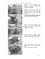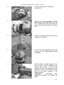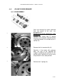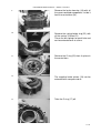
1
USE AND MAINTENANCE MANUAL – SERIES S128 AXLES
CONTENTS
1. PRELIMINARIES .......................................................... 2
1.1.
1.2.
1.3.
INTRODUCTION ..........................................................................................................2
ID PLATE .......................................................................................................................2
SAFETY NOTES...........................................................................................................3
2. PROGRAMMED MAINTENANCE ................................ 4
2.1.
OIL CHANGE AND PERIODIC AL CONTROLS ......................................................4
3. TROUBLESHOOTING ................................................. 6
3.1.
TROUBLESHOOTING.................................................................................................6
4. EXTRAORDINARY JOBS ............................................ 9
4.1. STEERING COMPONENTS.................................................................................... 11
4.1.1. DISASSEMBL Y.................................................................................................. 11
4.1.2. ASSEMBL Y ........................................................................................................ 13
4.2. KNUCKLE AND WHEEL HUB................................................................................. 16
4.2.1. DISASSEMBL Y.................................................................................................. 16
4.2.2. ASSEMBL Y ........................................................................................................ 22
4.3. PLANET GEAR HOLDER HUB............................................................................... 31
4.3.1. DISASSEMBL Y.................................................................................................. 31
4.3.2. ASSEMBL Y ........................................................................................................ 33
4.4. OIL BATH DISK BR AKES ........................................................................................ 35
4.4.1. DISASSEMBL Y.................................................................................................. 35
4.4.2. ASSEMBL Y ........................................................................................................ 40
4.4.3. MECHANIC ALLY DISENGAGING THE NEGATIVE BR AKE .................... 46
4.5. LATER AL BEAM........................................................................................................ 47
4.5.1. DISASSEMBL Y.................................................................................................. 47
4.5.2. ASSEMBL Y ........................................................................................................ 50
4.6. STAND ARD AND LSD DIFFERENTIAL HOUSING ............................................ 55
4.6.1. DISASSEMBL Y.................................................................................................. 55
4.6.2. ASSEMBL Y ........................................................................................................ 57
4.7. CENTRAL BOX AND BEVEL PINION ................................................................... 60
4.7.1. DISASSEMBL Y.................................................................................................. 60
4.7.2. ASSEMBL Y ........................................................................................................ 62
5. TESTING AND FINAL INSTRUCTIONS .................... 66
5.1.
5.2.
TESTINGS .................................................................................................................. 66
FINAL INSTRUCTIONS............................................................................................ 66
1 / 66
USE AND MAINTENANCE MANUAL – SERIES S128 AXLES
1. PRELIMINARIES
1.1.
INTRODUCTION
This manual contains information necessary for carrying out extraordinary maintenance
on the differential axle if ever repairs are required of malfunctions connected to it.
By always following the instructions given in this manual, the number of hours required
for disassembly and assembly will be far less and the risk of incorrect maintenance work
minimised.
The certainty of a repair job well done is entrusted to people who do this work. It is
therefore important that the people assigned to such work receive detailed information
about restoring the correct conditions that guarantee operation of the differential axle,
limited to the purposes for which it has been designed.
This handbook intends explaining to those who actually carry out the e xtraordinary
maintenance work on the product, which are the criteria to follow to attain the final result:
re-establish and guarantee functionality of the differential axle over time.
Hence, this manual must be read by persons authorised to make repairs before they
start any such work in order to guarantee the best result.
1.2.
ID PLATE
Axle identification plate
CODE
SERIAL NO.
Errore. L'orig ine rif erimento non è stata trovata.
2 / 66
USE AND MAINTENANCE MANUAL – SERIES S128 AXLES
1.3.
SAFETY NOTES
The observance and respect of all existing safety requirements and laws are absolutely
essential to protect people from injury and safeguard the product and environment from
damage. The repair technicians must have specific skills and expertise to repair these
differential axles or similar ones. Without such knowledge, specific training courses
must be organised and held by authorised personnel. Repair work must only be done
after having read and completely understood all what is written in the instruction Manual
as regards to repairs.
Before doing any work on the axles, still mounted, the vehicle must be made safe:
- Park the vehicle on a flat, solid surface.
- Put the work equipment on the ground.
- Engage the parking brake.
- Turn the engine off.
- Take the key out of the ignition.
- Lock the wheels of the vehicle with a wedge.
- Scrupulously observe the indications given on the warning and indication plates that
are on the vehicle.
All auxiliary means and tools must be in perfect condition for use and absolutely safe.
Errore. L'orig ine rif erimento non è stata trovata.
3 / 66
USE AND MAINTENANCE MANUAL – SERIES S128 AXLES
2. PROGRAMMED MAINTENANCE
2.1.
OIL CHANGE AND PERIODICAL CONTROLS
Lubricants :
SAE 85W90 (API GL4) with additives for oil bath brakes
Examples of usable oils: Mobil Super Universal 20W40, Mobil Fluid 422, ELF SF3,
AGIP MULTI THT 80W
For axles with self-locking differential:
SAE 85W90 (API GL5) with additives for oil bath brakes and additives for self-locking
differential (LS Limited Slip).
Examples of usable oils: SHELL SPIRAX HD 85W90, FUCHS TITAN GEAR 85W90 LS,
CASTROL LSC SAE 90, ELF SF3
In both cases we recommend “Shell Donax TD”
Brake oil:
Use only “Agip ATF II D” mineral oil or alternatively ATF Dexron II oil for the braking
system.
Grease:
We recommend using “Shell Retinax HDX2” grease.
The maintenance intervals mentioned are for a normal use of the vehicle; intervals
should be shorter if the vehicle is used for particularly hard work.
Job
Changing axle oil
Cleaning the magnetic oil drainage plug
Checking and topping up the oil
Cleaning the oil breather
Greasing (where envisaged)
First intervention
200 hours
at the first oil change
100 hours
400 hours
200 hours (2)
Routine maintenance
seasonal/ every 1000 hours (1)
at every oil change
monthly / every 300 hours (1)
monthly / every 300hours (1)
weekly / every 200 hours (1)(2)
(1) which of the two conditions occurs first
(2) 50 hours in the case of hard work
Errore. L'orig ine rif erimento non è stata trovata.
4 / 66
USE AND MAINTENANCE MANUAL – SERIES S128 AXLES
Axle oil level plug
Axle oil drainage plugs
Wheel hub draining-filling level plug
Axle oil filling and
breathing plug
Changing the oil:
Check the position of the plugs and their function on the axle’s dimensional drawing.
Make sure the vehicle is on a flat surface, position the collection trays appropriately and
then unscrew the oil drainage plugs.
Wait for all the oil to drain from the axle.
Filling the rigid axle:
The various chambers of the axle are joined together and it is the axle level plug that
defines the correct oil level.
Pour the oil in through the filling plugs until it starts coming out of the level plug; keep
the holes on the hubs open, located above the centre line, to help the air flow.
Filling the steering axle:
The chambers of the steering units are separate from the axle chambers.
Pour the oil in through the filling up plug, located centrally, until the level defined by the
level plug is reached.
There is just one plug on the steering unit that has the function of draining, level or filling
up depending on the position it is in.
When it is in the lowest position it acts as the drainage plug, when it is on the centre
position it acts as the filling up and level plug.
Caution: oil takes time to distribute so you have to wait a few minutes and then add
some more oil; continue like this until the level stops going down.
Errore. L'orig ine rif erimento non è stata trovata.
5 / 66
USE AND MAINTENANCE MANUAL – SERIES S128 AXLES
3. TROUBLESHOOTING
3.1.
TROUBLESHOOTING
PROBLEM
Bevel gear:
CAUSE
1. Gear load is much
greater than expected
Breakage towards the
2. Incorrect gear
external
adjustment (too much
end of the gear tooth
clearance)
3. Pinion ring nut has come
loose.
Bevel gear:
1. Knocked by the load
2. Incorrect gear
Breakage
towards
the adjustment (too little
internal end of the gear clearance)
tooth
3. Pinion ring nut has come
loose.
Bevel gear:
1. Insufficient lubrication
2. Lubricant is dirty
Pinion and gear teeth
3. Wrong lubricant or with
are worn or scored
impoverished additives
4. Pinion bearings are
worn, causing incorrect
axial clearance of the
pinion and contact between
pinion and gear
Bevel gear:
1. Prolonged operation at
Pinion and gear teeth
excessive temperatures.
overheated. See if the 2. Wrong lubricant
colour of the gear teeth has 3. Low oil level
altered
4. Lubricant is dirty
Bevel gear:
1. Extremely intense use
Pitting of pinion teeth
2. Insufficient lubrication
Bevel gear:
1. Excessive use
Breakage due to fatigue of 2. Continuous overload
the pinion tooth (check for
characteristic fracture lines)
Bevel gear:
Impact
load
of
the
differential’s components
Sudden breakage of the
pinion and gear teeth
Differential unit:
Extremely intense use
Differential planet gear
Errore. L'orig ine rif erimento non è stata trovata.
ACTIONS
Replace the bevel gear.
Follow the steps carefully
that are recommended for
adjusting gear tooth and
pinion clearance and for
detecting tooth impression.
Replace the bevel gear.
Follow the steps carefully
that are recommended for
adjusting gear tooth and
pinion clearance and for
detecting tooth impression.
Replace the bevel gear.
Replace the pinion’s
bearings, making sure the
gear, pinion and bearing
preloads are arranged
correctly.
Use the correct lubricant,
fill up to the right level and
change it at the intervals
recommended.
Replace the bevel gear.
Use the correct lubricant,
fill up to the right level and
change it at the intervals
recommended.
Replace the bevel gear.
Use the correct lubricant,
fill up to the right level and
change it at the intervals
recommended.
Replace the bevel gear.
Check and/or replace other
differential components.
Replace the differential
unit. Replace the shaft if
6 / 66
USE AND MAINTENANCE MANUAL – SERIES S128 AXLES
grooving worn (too much
clearance)
Differential unit:
1. Insufficient lubrication
Surfaces of the washers of 2. Wrong lubrication
the differential gears are 3. Lubricant is dirty
worn or marked
Pinion unit:
Inlet
flange’s
coupling is worn
1. Extremely intense use
grooved 2. Pinion ring nut or flange
locking screw has come
loose.
3. Pinion axial clearance
Beam:
The axle’s lateral beam is
damaged.
Bearings:
Wear and pitting of the
bearings. Change in colour.
Seals and gaskets:
Oil leaks from seals and
gaskets
1. Vehicle overloaded.
2. Vehicle involved in an
accident.
3. Knocked by the load.
1. Insufficient lubrication
2. Lubricant is dirty
3. Extremely intense use
4. Normal wear
5. No longer adjusted
correctly.
6. Excessive overheating.
1. Prolonged operation with
excessive oil temperature.
2. Oil seal fitted in a wrong
way
3. Edge of the seal is cut or
corroded
4. Lubricant is dirty
Extremely intense use of
the vehicle, overloaded
Shaft:
Shaft deformed or fracturesplit
Noise:
1. Too much clearance
between the gear and
Noise when driving
pinion
2. Pinion and gear are worn
3. The pinion bearings are
worn
4. Pinion bearings with
clearance
5. Differential bearings are
worn
6. Differential bearings with
clearance
7. Gear not in position
8. Lubricant level low
Errore. L'orig ine rif erimento non è stata trovata.
necessary.
Replace all the washers
marked and those that are
0.1 mm thinner than the
new ones.
Use the correct lubricant,
fill up to the right level and
change it at the intervals
recommended.
Replace the flange
Check that the grooving of
the pinion is not
excessively worn
Replace the bevel gear if
necessary.
Replace the axle’s lateral
beam
and any other
damaged components.
Replace the bearings.
Use the correct lubricant,
fill up to the right level and
change it at the intervals
recommended.
Adjust them correctly.
Replace the seal and
coupling surfaces if
damaged.
Use the correct lubricant,
fill up to the right level and
change it at the intervals
recommended.
Replace the shaft
1. Adjust
2. Replace
3. Replace
4. Adjust
5. Replace
6. Adjust
7. Replace
8. Top up
9. Replace
10. Replace
11. Replace
12. Replace
13. Replace
7 / 66
USE AND MAINTENANCE MANUAL – SERIES S128 AXLES
Noise:
Noise when idling
Noise:
Intermittent noise
Noise:
Noise on a curve
9. Wrong lubricant
10. Shaft is bent
11. Cardan shaft with too
much clearance on the
spider.
12. Wheel hub bearings
worn.
13. Wheel unit gears are
excessively
worn
or
damaged.
1. Noise coming from the
axle
with the vehicle moving are
usually heard when idling
even if not very loud
2. Incorrect clearance
between pinion and gear
(the noise heard when
decelerating disappears as
speed increases).
3. Pinion or inlet flange’s
grooved coupling is worn
1. Gear damaged
2. The screws closing the
differential unit housing are
loose.
1. Differential planet gears
worn
2. Differential housing
and/or differential pins worn
3. Differential washers
worn
4. Grooving on the shaft
worn
Errore. L'orig ine rif erimento non è stata trovata.
1. Adjust or replace (see
above)
2. Adjust
3. Replace
1. Replace the gear
2. Tighten to torque
1. Replace
2. Replace
3. Replace
4. Replace
8 / 66
USE AND MAINTENANCE MANUAL – SERIES S128 AXLES
4. EXTRAORDINARY JOBS
DISASSEMBL Y
Before carrying out any maintenance work the outside of the transmission must be
cleaned with a jet of steam. Seal all openings before doing this so that water and dirt
cannot get inside and damage the fundamental parts.
To disassemble the axle parts the axle itself has to be taken off the vehicle first. This
also entails removing the wheels and the hydraulic pipes from the braking circuit as well
as draining the oil from the differential and hubs, removing the plugs.
When disassembly is finished, carefully remove the dirt from each single piece, throwing
away all those parts that (due to their nature) when assembling, have to be replaced
with others in perfect condition: gaskets, seals, worn bearings, screws with worn thread
ASSEMBL Y
More than 90% of the bearings break due to dirt which is always abrasive. Dirt can get
inside the transmission during assembly or be transported by the lubricant during
operation. Dirt can also get inside by way of the seals, outlet plugs or even by means of
the containers for filling up and changing the oil.
Prior to assembly each piece must be cleaned thoroughly and those parts that require it
oiled. The components that need oiling must be lubricated with new oil before being
assembled.
NOTE: When reassembling it is essential to replace all the seals. Take care NOT to
pinch the oil retainers during assembly.
9 / 66
USE AND MAINTENANCE MANUAL – SERIES S128 AXLES
SPECIAL TOOLS
Ref.
Code
Paragraph
Description
T01
4.2.2
Wheel hub tapered roller bearing cup driver
T02
4.2.2
Wheel hub cassette seal driver
T03
4.2.2
Bearing on wheel spindle driver
T04
4.2.2
Accessory for wheel hub bearing rolling torquemeter
T05
4.2.2
Wheel driver gear on stud bolts driver
T06
Knuckle housing bush driver
T08
4.2.2
4.5.2
4.2.2
4.5.2
4.2.2
T09
4.3.2
Driver for the needle unit in the planet gear
T10
4.4.2
Spring bushing driver.
T11
4.4.2
Piston insertion driver
T12
4.4.2
Piston insertion driver
T13
4.4.2
Brake assembly equipment
T14
4.5.2
Ball bearing driver
T15
4.5.2
Differential bearing cups driver
T16
4.7.2
Pinion bearing cups driver equipment
T17
4.7.2
Pinion bearing driver
T18
4.7.2
Accessory for torquemeter to check pinion torque
T07
Knuckle housing sealing rings driver
Accessory for knuckle housing bearing rolling
torquemeter
Note: The special tools can be purchased directly from Comer Industries or a drawing
can be furnished at the Customer’s request.
10 / 66
USE AND MAINTENANCE MANUAL – SERIES S128 AXLES
4.1.
STEERING COMPONENTS
4.1.1. DISASSEMBLY
1
Remove the nut (4).
2
Separate the steering tie rod (3) from
the knuckle.
3
Unscrew the steering tie rod (3) from
the steering cylinder piston rod (1).
11 / 66
USE AND MAINTENANCE MANUAL – SERIES S128 AXLES
4
Remove the securing screws (2) of the
steering cylinder (1) to the central
housing and retrieve it.
12 / 66
USE AND MAINTENANCE MANUAL – SERIES S128 AXLES
4.1.2. ASSEMBLY
1
Before starting to install the steering
cylinder (1) on the central housing check
that the cylinder piston rod is centred in
relation to the mid-plane, making sure
that the piston rod projects equally on
both sides.
If necessary, centre the piston rod by
knocking on the end with a hammer.
2
Place the steering cylinder (1) on the
central housing using the securing
screws (2).
Tighten the screws with a torque wrench
to a torque of 15 daNm.
3
Screw the tie rod (3) on to the steering
cylinder piston rod (1) with a squarehead wrench (T01) using some Loctite
243.
Tighten the tie rod to a torque of 15
daNm.
13 / 66
USE AND MAINTENANCE MANUAL – SERIES S128 AXLES
4
Position the cone of the tie rod (3) in its
place on the knuckle.
5
Tighten the nut (4) to a torque of 28
daNm.
6
Check toe-in/toe-out of the steering
system by installing a bar on each rim
plane.
Measure the distance between the two
bars at the front (steering cylinder side)
and at the back (drive shaft side) of the
axle.
ATTENTION: the difference between the
2 measurements must not exceed 1
mm.
Turn the steering tie rod as illustrated in
the figure to achieve bar parallelism:
with one wrench hold the cylinder piston
rod perfectly still while with the other
wrench tighten/loosen the internal thread
of the steering tie rod.
7
8
Once parallel, tighten the check nut of
the steering tie rod’s internal thread to a
torque of 15 daNm and check
adjustment of the end of travel screws
on the knuckle housing.
14 / 66
USE AND MAINTENANCE MANUAL – SERIES S128 AXLES
9
If a knuckle housing has to be replaced,
steer the wheels until one of the
housing’s two stops, already adjusted,
reaches the end of travel.
1
0
Unscrew the stop on the replaced
housing until it comes into contact and
then tighten the check nut to a torque of
20 daNm using some Loctite 270.
Repeat this, steering in the opposite
direction.
1
1
If both knuckle housings are replaced,
measure the steering angle and then
move the two stops until they come into
contact (right wheel and left wheel),
tighten the check nut to a torque of 20
daNm with Loctite 270 and repeat but
measuring the angle when steering in
the opposite direction.
15 / 66
USE AND MAINTENANCE MANUAL – SERIES S128 AXLES
4.2.
KNUCKLE AND WHEEL HUB
4.2.1. DISASSEMBLY
ATTENTION fasten the steering wheel
reduction assembly to a suitable
support.
1
Remove the securing screws (7) and
extract the bottom knuckle pin (6).
2
Remove the lubricator (5)
16 / 66
USE AND MAINTENANCE MANUAL – SERIES S128 AXLES
3
Remove the securing screws (7) of the
top knuckle pin.
4
Extract the top knuckle pin (6) and the
shims (8).
5
Retrieve the shims (8).
6
Retrieve the bearing (6*).
7
Separate the steering wheel reduction
assembly with double joint from the
lateral beam.
17 / 66
USE AND MAINTENANCE MANUAL – SERIES S128 AXLES
8
Remove the two screws (29) securing
the planet gear supporting subunit to
the hub.
9
Separate the hub planet gear holder
subunit (26) from the knuckle unit.
ATTENTION: do not let the drive fall –
support it with a rope if necessary.
10
Retrieve the O ring (25) from the hub.
11
Remove the seeger ring (24).
12
Remove the washer (23).
18 / 66
USE AND MAINTENANCE MANUAL – SERIES S128 AXLES
13
Pull the double joint (1) out from the
knuckle (4).
14
Remove the eight nuts (21) from the
stud bolts (9).
15
Remove the closing ring (22).
16
Use two levers to separate the gear
holder-gear subunit (14+18+19) from
the knuckle housing.
NOTE: if the axle is rigid, the subunit is
installed directly on the lateral beam.
17
Retrieve the shims (20).
19 / 66
USE AND MAINTENANCE MANUAL – SERIES S128 AXLES
18
Remove the spring ring (14) retaining
the gear holder with the aid of a
screwdriver.
19
Separate the gear holder (18) from the
gear (19).
20
Remove the wheel hub
(10+11+12+13) from the
housing (4) with an extractor.
21
Separate the hub subunit and retrieve
the external bearing (13).
22
Use an extractor to remove the internal
bearing (11) from the knuckle housing.
subunit
knuckle
20 / 66
USE AND MAINTENANCE MANUAL – SERIES S128 AXLES
23
Remove the 2 sealing rings (2) from the
knuckle housing (4) with a screwdriver.
24
Remove the bushing (3) from the
knuckle housing (4) with a screwdriver.
Note: Both the sealing rings (2) and
bushing (3) must always be replaced.
25
Remove the internal and external
bearing cups (11 and 13) from the
wheel hub (12) with a screwdriver.
Remove the sealing ring (10) with a
screwdriver.
Note: The sealing ring must always be
replaced.
21 / 66
USE AND MAINTENANCE MANUAL – SERIES S128 AXLES
4.2.2. ASSEMBLY
1
Drive in the cup of the external tapered
roller bearing (13) on the wheel hub
(12) with the special tool (T01).
2
Drive in the cup of the internal tapered
roller bearing (11) on the wheel hub
(12) with the special tool (T01).
3
Fit the cassette seal (10) on the wheel
hub (12) with the special tool (T02).
22 / 66
USE AND MAINTENANCE MANUAL – SERIES S128 AXLES
4
5
Drive in the internal tapered roller
bearing (11) on the spindle of the
knuckle
housing
(4)
with
the
appropriate tool (T03).
Attention: if the axle is rigid, the
operations are to be done from this
stage up to point 4.22 on the rigid
housing spindle and not on the knuckle
housing.
Mount the preassembled hub subunit
on the knuckle housing (4) taking care
not to damage the sealing ring (10).
6
Drive in the external tapered roller
bearing (13) on the spindle of the
knuckle
housing
(4)
with
the
appropriate tool (T03).
7
With the aid of a rubber headed
hammer, arrange and adjust the wheel
hub bearings to eliminate the preload.
8
Use a torquemeter to check drive
torque due to just the oil retaining ring
(10).
(T04) Accessory for torquemeter.
23 / 66
USE AND MAINTENANCE MANUAL – SERIES S128 AXLES
9
Place the shims (20) on the gear holder
(18).
10
Mount the gear holder with shims on
the preassembled knuckle housing.
11
Position the closing ring (22).
12
TEMPORARIL Y tighten eight M12 x
1.25x35 screws to a torque of 10
daNm.
Attention: do not use any LOCTITE.
13
Once the bearings have been adjusted
again on the hub, check the preload
value measured as rolling torque with a
torquemeter. Accessory (T04).
The rolling torque of only the bearings
without the oil retaining ring should be
between 125 and 155 daNcm.
If necessary, remove the gear holder
and change the number of shims (20).
24 / 66
USE AND MAINTENANCE MANUAL – SERIES S128 AXLES
14
When the correct preload is reached,
remove the eight temporary screws, the
closing ring (22), the gear holder (18)
and retrieve the shims (20).
15
Mount the gear holder (18) on the gear
(19).
16
Fit the spring ring (14) retaining the
gear holder.
Position the number of shims (20)
checked previously on the gear holder
(18).
17
Tighten the stud bolts (9) on the
knuckle housing (4) using some Loctite
270.
Tighten to a torque of 6 daNm.
18
Mount the preassembled gear subunit,
gear holder and shims on the knuckle
housing with the appropriate driver
(T05)
25 / 66
USE AND MAINTENANCE MANUAL – SERIES S128 AXLES
19
Position the closing ring (22).
20
Tighten the nuts (21) on the stud bolts
(9) using some Loctite 243.
21
Tighten the nuts (21) to a torque of 10
daNm.
22
Screw the pin-stud bolts (15) on the
hub (12) using some Loctite 270.
Tighten to a torque of 20 daNm.
Note: If the axle is rigid, simply insert
the axle shaft, releasing the negative
brake if there is one, and then go
straight to phase 4.2.2.28 up to
4.2.2.31.
26 / 66
USE AND MAINTENANCE MANUAL – SERIES S128 AXLES
23
Turn
the
preassembled
knuckle
housing subunit upside down and put
the bushing (3) in place with the
specific tool (T06).
24
Fit the 2 sealing rings (2) on the
knuckle housing (4) using the special
Tool (T07).
Apply some Polymer 400 grease.
25
Insert the double cardan joint (1) in the
knuckle housing (4) being careful not to
damage the sealing rings (2).
26
Fit the washer (23).
27
Fit the Seeger ring (24).
27 / 66
USE AND MAINTENANCE MANUAL – SERIES S128 AXLES
28
Put the O-Ring (25) in its place on
the hub (12).
29
Position the preassembled satellite
gear holder hub subunit (26) on the
hub, matching the holes with those of
the securing screws (29) on the wheel
hub.
30
Tighten the two securing screws (29) to
a torque of 4.5 daNm.
31
Fit the oil filling up/draining plug (28)
with washer (27), tightening to a torque
of 5 daNm.
32
With the aid of a suitable support, insert
the knuckle subunit complete with
double cardan joint in the housing,
making sure that the grooving on the
differential side of the double cardan
joint fits into place correctly in the
differential gear.
WARNING!
RELEASE
THE
NEGATIVE BR AKE, IF THERE IS
ONE.
28 / 66
USE AND MAINTENANCE MANUAL – SERIES S128 AXLES
33
Fit the ball bearing (6*) on the knuckle
pin (6).
34
Position the shims (8) on the top ball
knuckle pin (6).
35
Mount the top ball knuckle pin (6) on
the housing, partially tightening the
screws (7)
36
Mount the bottom ball knuckle pin (6).
37
Tighten the screws (7) to a torque of 15
daNm.
29 / 66
USE AND MAINTENANCE MANUAL – SERIES S128 AXLES
38
Tighten the screws (7) of the top ball
knuckle pin to a torque of 15 daNm.
39
Check the preload value of the
ball knuckle bearings measured as
rolling torque with a torquemeter.
Rolling torque should be between 5 and
8 daNm.
(T08) Accessory for torquemeter
If necessary, remove and change the
number of shims (8).
40
Mount the lubricators on the top and
bottom ball knuckle pins (5).
Tighten them to a torque of 1.5 daNm.
30 / 66
USE AND MAINTENANCE MANUAL – SERIES S128 AXLES
4.3.
PLANET GEAR HOLDER HUB
4.3.1. DISASSEMBLY
1
Remove the two screws securing the
planet gear holder support subunit to the
hub.
2
Separate the planet gear holder support
subunit and lay it on a flat surface.
3
Take the Seeger ring (4) off with a pair
of pliers.
31 / 66
USE AND MAINTENANCE MANUAL – SERIES S128 AXLES
4
Remove the three planet gears (5) with
an extractor and separate the needle
bearing (3).
5
Check the state of wear of the parts,
replacing them if necessary.
If the axle shaft stopper is damaged
replace the whole planet gear holder (1
and 2).
32 / 66
USE AND MAINTENANCE MANUAL – SERIES S128 AXLES
4.3.2. ASSEMBLY
1
Punch mark the axle shaft stopper (2) in
3 points on the planet gear holder (1).
2
Mount the needle bearing (3) on the
planet gear (5) with the special tool
(T09).
3
Check correct mounting of the needle
bearing (3) on the planet gear (5) with a
depth gauge.
The depth measured in the figure must
be equal to 6 (+/- 0.5) mm.
33 / 66
USE AND MAINTENANCE MANUAL – SERIES S128 AXLES
4
Position the planet gear (5) with
preassembled needle bearing on the
pin of the planet gearholder (1) taking
care to position it in the direction shown
in the figure.
The rounded end of the needle bearing
(3) is to go at the bottom.
5
Drive in the planet gear with needle
bearing (5 + 3) on the planet gear
holder pin (1) with the special tool
(T09).
6
Fit the retaining Seeger ring (4) on the
pin.
To make doubly sure that mounting is
correct, check that the surface of the
planet gear and the machined surface
of the pin are the same height.
34 / 66
USE AND MAINTENANCE MANUAL – SERIES S128 AXLES
4.4.
OIL BAT H DISK BRAKES
4.4.1. DISASSEMBLY
1
2
Once the housing has been removed
from the centre of the axle, see
paragraph 4.5.1
Removing the brake components from
the housing:
Remove the spring ring (7) paying
attention to the counter steel disk which
is pushed towards the outside by the 2
springs (3).
Remove the first counter disk (6).
Attention: if the brake disk package
does not have to be replaced we
suggest numbering the position of the
counter disks and disks to ensure they
are put back in the same position.
3
Retrieve the 2 springs (3).
35 / 66
USE AND MAINTENANCE MANUAL – SERIES S128 AXLES
4
Remove the first brake disk (5), the
following counter disk (6) and the
second brake disk (5) in this order.
5
Remove the bushing (4).
6
Remove the steel counter disk (6).
7
Remove the last brake disk (5).
8
Disassembling the brake unit:
Remove the screws (25) securing the
brake housing (16) to the central box
(24).
36 / 66
USE AND MAINTENANCE MANUAL – SERIES S128 AXLES
9
Remove the brake housing (16) with all
the preassembled components inside it
from the central box (24).
10
Remove the spring holder ring (22) with
all the springs (20 and 21).
There are two springs for each hole and
can be extracted one at a time.
11
Retrieve the O ring (23) from its place in
the central box.
12
The negative brake piston (19) can be
extracted with compressed air.
13
Take the O ring (17) off.
37 / 66
USE AND MAINTENANCE MANUAL – SERIES S128 AXLES
14
Take the O ring (18) off.
15
Unscrew the nuts (8).
16
Retrieve the washers (9) and spacers
(11)
17
Push the piston (13) from the side
opposite the brake housing (16) to
remove it.
18
Take the two O rings (14 and 15) out.
38 / 66
USE AND MAINTENANCE MANUAL – SERIES S128 AXLES
19
Unscrew the stud bolts (12).
20
Use a punch driver to take the spring
bushes (10) out of the piston (13).
39 / 66
USE AND MAINTENANCE MANUAL – SERIES S128 AXLES
4.4.2. ASSEMBLY
1
Assembling the brake unit:
Drive (with tool T10) the spring bushes
(10) in the piston (13), inserting them
from the rounded part and pushing
them right down to the opposite surface
of the flange.
The surface of the rounded part of the
bush must be the same height as the
piston surface.
2
Mount the stud bolts (12) with some
Loctite 270, tightening them to a torque
of 1.5 daNm
40 / 66
USE AND MAINTENANCE MANUAL – SERIES S128 AXLES
3
Put the oiled O ring (14) in its place.
4
Put the oiled O ring (15) in its place.
5
Position the piston (13) in the correct
phase, determined by the stud bolts
and by the two projecting parts of the
piston.
6
Put the piston (13) in its place, taking
care not to damage the O rings.
(T11) Driver
7
Put the spacers (11) in place.
41 / 66
USE AND MAINTENANCE MANUAL – SERIES S128 AXLES
8
Fit the washers (9).
9
Put the self-locking nuts (8) in and
tighten them to a torque of 1.2 daNm
10
Put the adequately oiled O ring (18) in
place.
11
Put the adequately oiled O ring (17) in
place.
12
With the appropriate driver (T12) put
the piston (19) in its place, taking care
not to damage the O rings.
42 / 66
USE AND MAINTENANCE MANUAL – SERIES S128 AXLES
13
Put the spring holder ring (22) in its
place obtained in the central box (24).
14
Put the O ring (23) in its place obtained
in the central box.
15
Put the springs (20 and 21) in each hole
of the flange (22).
16
Drive the pins (26) into the central box.
17
Position the brake unit on the central
box and tighten the screws (25) to a
torque of 4.5 daNm.
In the presence of a negative brake and
before proceeding with the next
operations, power the negative brake
circuit with a pressure of at least 15 bar
(no more than 30 bar) and then, with a
rubber headed hammer, move the
positive brake piston (13) back into its
initial position against the inner surface
43 / 66
USE AND MAINTENANCE MANUAL – SERIES S128 AXLES
seeing as when the securing screws of
the brake unit were tightened, it was
pushed towards the outside by the
springs (20 and 21).
Alternatively, axle assembly can be
completed but in this case, before
installation on the vehicle, it will be
necessary to proceed as explained in
paragraph 4.4.3, but this time tightening
the screws right down.
18
Put the O ring in its place obtained in
the brake unit housing.
Insert a brake disk (5) in the lateral
beam (1).
19
Then insert the steel counter disk (6).
20
Insert the bush (4) as shown in the
figure.
44 / 66
USE AND MAINTENANCE MANUAL – SERIES S128 AXLES
21
Insert the second brake disk (5)
followed by the second steel counter
disk (6) and lastly the third brake disk
(5).
Pay attention to the brake disks – they
must be put so the passage holes
match.
22
Insert the 2 springs (3) in the two blind
holes in the housing (1).
23
Position the last counter disk (6).
24
Either using the tool (T13) or keeping
the counter disk pressed, put the spring
ring (7) in its place in the housing (1).
25
Check correct opening of the spring
ring.
The open part of the ring must coincide
with the threaded oil drainage hole.
Mount the housing on the central part,
see paragraph (4.5.2)
45 / 66
USE AND MAINTENANCE MANUAL – SERIES S128 AXLES
4.4.3. MECHANICALLY DISENGAGING THE NEGATIVE BRAKE
If there is a failure with the vehicle and
it needs to be towed, the negative brake
(where foreseen) will need to be
mechanically disengaged.
Attention!!!
When mechanically disengaging the
negative brake, the service brake will
be unusable therefore the vehicle must
be kept still and safe using suitable
methods (ropes, wedges, etc.)
Completely undo the 2 screws (1) on
the beam (3), remove the spacer 2 and
then retighten the screws (1) on the
beam (3).
Attention: the screws must be tightened
alternately, turning them 45° at a time;
do not tighten completely one screw
and then the next.
It is unnecessary to tighten the screws
completely – stop as soon as the brake
is disengaged.
Proceed in the reverse order to reengage the negative brake.
46 / 66
USE AND MAINTENANCE MANUAL – SERIES S128 AXLES
4.5.
LATERAL BEAM
4.5.1. DISASSEMBLY
1
Put the axle on supports able to
withstand the weight of the central body
and the two lateral beams even after
they have been separated or anchor the
three units individually with ropes or
belts to a lifting system.
Undo the screws (11) of the beam and
retrieve the washers.
2
Separate the lateral beam (5) from the
central unit.
ATTENTION do not let the flange (8)
fall that is supporting the differential
unit.
If the a xle has brakes see (4.4.1)
3
Remove the o-ring (7)
47 / 66
USE AND MAINTENANCE MANUAL – SERIES S128 AXLES
4
Remove the flange (8)
5
Remove the bearing cap (15)
Attention: if the axle has brakes then
this and the next 2 operations are to be
done inside the brake unit.
6
Retrieve the shims (13).
7
Take the Seeger ring (12) out of its
place.
8
Retrieve the felt rings (3).
48 / 66
USE AND MAINTENANCE MANUAL – SERIES S128 AXLES
9
Use the extractor to remove the
spherical cap (4) from the housing.
10
Remove the two oil retaining rings (1)
with a screwdriver.
11
Remove the
screwdriver.
bush
(2)
with
a
49 / 66
USE AND MAINTENANCE MANUAL – SERIES S128 AXLES
4.5.2. ASSEMBLY
1
2
If the a xle is rigid go to phase 4.
Drive the bushing (2) with the special
tool (T06) into the housings (5).
Drive 2 sealing rings (1) into the housing
(5 ) with the special tool (T07).
Grease the oil retainers
with Polymer 400
50 / 66
USE AND MAINTENANCE MANUAL – SERIES S128 AXLES
3
Drive in the spherical cap (4) with the
tool (T14)
4
Put the Seeger ring (12) in its place.
5
Insert the shims (13).
Roughly the same number of shims that
were there when disassembling must be
put back. It will later be checked to see if
the number is correct.
6
Drive in the bearing cap (15) with the
tool (T15)
51 / 66
USE AND MAINTENANCE MANUAL – SERIES S128 AXLES
7
Brush some of the gear and pinion teeth
with a marking product (i.e. ink) to later
verify perfect contact of the bevel gear
teeth.
8
Put the flange (8) in its place.
Note: If it is the flange on the differential
gear side you will first need to put the
differential unit inside the central box.
9
Put the O rings (7) and pins (14) in place
in the central box.
10
Arrange the housing (5) on the central
box, turning the flange (8) underneath if
necessary, depending on the position of
the hollow in the housing.
11
Tighten the screws (11) with their
washers to a torque of 15 daNm
52 / 66
USE AND MAINTENANCE MANUAL – SERIES S128 AXLES
ADJUSTING
ADJUSTING
12
The number of shims (13) for adjusting
the tapered roller bearings (15) must be
such to have a clearance of 0.15 to 0.30
mm between the teeth of the bevel gear
and bearing (14) pre-load measured as
an INCREASE of the rolling torque in
input to the pinion must be as given in
the following table.
ratio
C/C
rolling torque INCREASE
measured on the pinion with a
torquemeter
(daNcm)
9:37
12:39
14:38
17:38
3-5
4-7
4-8
5 - 10
Measure the clearance between gear
and bevel pinion.
Measure the
torquemeter.
ADJUSTING
13
rolling
torque with
a
Mo ve some of the shims (13) from the
bearing on the right to the bearing on
the left to either increase or reduce
torque clearance, increase or reduce the
number of shims to increase or reduce
the rolling torque.
This does mean of course that the
lateral beams will have to be
disassembled and re-assembled if the
axle has no brakes.
If the axle does have brakes, simply
remove the Seeger (12) leaving the
brake units in place.
Check the goodness of the contacts
between
the
bevel
gear
teeth,
disassembling and reassembling the
lateral beam (on the gear side)
completely and extracting the differential
housing assembly.
An incorrect contact can give problems
of noise and duration of the bevel gear.
53 / 66
USE AND MAINTENANCE MANUAL – SERIES S128 AXLES
Use the pinion shims to correct contact
position, bringing clearance back to the
established values.
54 / 66
USE AND MAINTENANCE MANUAL – SERIES S128 AXLES
4.6.
STANDARD AND LSD DIFFERENT IAL HOUSING
4.6.1. DISASSEMBLY
1
Remove the two tapered roller bearings
(1) from the half housings (10) and (11)
using an extractor.
Retrieve the shims (2) from both sides
of the differential housing.
2
Undo the securing screws (8) of the
bevel crown (9) from the differential
housing and separate the crown gear.
3
Separate the differential half housings
(10) and (11).
55 / 66
USE AND MAINTENANCE MANUAL – SERIES S128 AXLES
4
Remove the planet gears (6) and
relative
spherical
washers
(5)
separating them from the spider (7).
5°
Retrieve the friction disk pack (3) of the
Limited Slip device from the planet gear
(4).
Check wear status and, if necessary,
replace the disk pack.
NOTE: keep the disk pack in the right
sequence to ensure correct assembly –
see figure.
5b
In versions with the STANDARD
differential, there is a washer on the
planet gear (4) instead of the friction
disk pack.
56 / 66
USE AND MAINTENANCE MANUAL – SERIES S128 AXLES
4.6.2. ASSEMBLY
1
Pre-assemble the planet gears (6) with
their spherical washers (5) on the
spider (7).
2°
Mount the friction disk pack (3) on the
planet gears (4).
NOTE: Observe the sequence of the
disks illustrated in the figure.
2b
In versions with the STANDARD
differential the washer must be used
instead of the friction disk pack.
57 / 66
USE AND MAINTENANCE MANUAL – SERIES S128 AXLES
3
Install the planet gears (4) in the half
housings (10) and (11).
4
Position the pre-assembled spider in
the differential half housing (10),
identified by its threaded holes.
5
Couple the half housing (11) to the half
housing (10), observing the matching
as indicated in the figure.
Refer to the matching of the two
numbers printed on the 2 half housings.
6
Mount the bevel crown (9) on the preassembled differential unit, tightening
the screws (8). Apply some Loctite 270
on the threads.
58 / 66
USE AND MAINTENANCE MANUAL – SERIES S128 AXLES
7
Tighten the screws (8) at a torque of 25
daNm.
59 / 66
USE AND MAINTENANCE MANUAL – SERIES S128 AXLES
4.7.
CENTRAL BOX AND BEVEL PINION
4.7.1. DISASSEMBLY
1
Remove the caulked ring nut (8)
2
Remove the anti-rotation washer (7)
3
Remove the tapered roller bearing (6),
knocking on the ends of the pinion with
a rubber headed hammer.
60 / 66
USE AND MAINTENANCE MANUAL – SERIES S128 AXLES
4
Retrieve the bevel pinion (2) and
remove the collapsible spacer (5).
ATTENTION: the collapsible spacer
must necessarily be replaced.
5
Remove the under-head tapered roller
bearing (3) from the pinion.
6
Remove the cup of the pinion underhead tapered roller bearing (3).
7
Retrieve the bevel gear set adjustment
shims (4).
8
Remove the cup of the external tapered
roller bearing (6).
61 / 66
USE AND MAINTENANCE MANUAL – SERIES S128 AXLES
4.7.2. ASSEMBLY
1
Read measurement “X” printed on the
head of the bevel pinion (2).
To find the right number of shims to set
adjust
the
bevel
gear,
find
measurement A (from the centre of the
housing to its edge) and the height
between the two surfaces of the
bearing (3).
All you need then do is subtract the
height of the bearing and the
measurement printed on the pinion
from measurement A and the result is
the height you have to have with the
shims.
2
Put the correct number of shims (4)
under the internal bearing cap (3).
Attention: this is fundamental to ensure
correct operation of the bevel gear.
62 / 66
USE AND MAINTENANCE MANUAL – SERIES S128 AXLES
3
Put the internal bearing cap (3) in
place.
4
Put the external bearing cap (6) in
place.
5
Put the two caps in place with the
relative tool (T16).
The caps can be driven in with a
hammer and driver but be sure they are
both positioned correctly.
6
Drive the bearing (3) on the pinion with
the tool (T17)
7
Insert the collapsible spacer (5) which
has to be replaced each time any work
is done on the pinion unit.
63 / 66
USE AND MAINTENANCE MANUAL – SERIES S128 AXLES
8
Put the pinion (2) in the central box (1).
9
After having seen to preparing an
adequate support for the pinion, drive in
the other bearing (6) with the driver
(T17).
10
Insert the washer (7) in the correct
phase with respect to the seat on the
pinion.
11
Tighten the ring nut (8) with some
Loctite 270 and keep the pinion blocked
and perfectly still until a rolling torque of
4 to 7 daNcm is reached
12
Measuring the rolling torque with a
torquemeter.
(T18) Accessory for torquemeter.
64 / 66
USE AND MAINTENANCE MANUAL – SERIES S128 AXLES
13
With a punch driver, caulk the ring nut
(8) in place on the pinion, taking care
not to break the edge of the ring nut.
65 / 66
USE AND MAINTENANCE MANUAL – SERIES S128 AXLES
5. TESTING AND FINAL INSTRUCTIONS
5.1.
TESTINGS
Block the input pinion. If the axle is installed on the vehicle, put it in gear.
With the help of another person standing on the other side, test correct assembly by
turning both wheels as much as possible moving forwards. (Both wheels should block
shortly after).
With the pinion still blocked, release the right wheel and turn the left wheel moving
forwards. If assembly is correct, the left wheel should be turning freely without any effort
and the right wheel should be turning (also freely) in the opposite direction (reverse).
Repeat in the opposite direction.
IF ONE OF THE WHEELS IS NOT TURNING FREELY check complete assembly of the
axle again.
5.2.
FINAL INSTRUCT IONS
Check correct filling up of the lubricating oil in the transmission. See paragraph 2.1.
Bleed the air from the circuit that feeds the oil bath disk brakes.
66 / 66