1
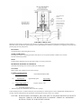
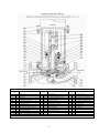
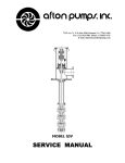
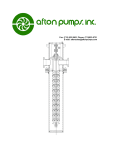
SERVICE MANUAL
MODEL ILVS
7335 Ave. N, P.O. Box 9426, Houston, Tx. 77261-9426
Fax: (713) 923-3902 Phone: (713)923-9731
E-mail: [email protected]
SERVICE MANUAL
GENERAL
shipment is found to have been defective at the time it was
shipped.
INTRODUCTION:
Afton pumps have been designed and
tested to give dependable, trouble-free service with
a minimum amount of attention. To insure
dependable operation the pump unit must be
properly installed, operated and serviced. Because
of the variety of installations in which these pumps
are used, this manual can only provide general
information. For specific information not contained
in this manual contact an Afton dealer.
The Purchaser must give Afton Pumps immediate written
notice upon finding such defect. Afton Pumps shall have the
option of requiring the return of the defective material
transportation prepaid, to establish the claim. Afton Pumps
shall in no event be held liable for damages or delay caused by
defective material and no allowance will be made for repairs
or alterations unless made with its written consent or
approval. Afton Pumps shall not be held responsible for work
done, apparatus furnished, or repairs made by others.
Warranty on equipment and accessories produced by
other manufacturers is limited to warranty of the respective
manufacturer.
WARRANTY:
Afton Pumps, Inc. warrants the equipment
of its manufacture against defects in material and
workmanship under normal use for a period of one
year after date of shipment. The Company’s
obligation under this warranty is limited, however,
to furnishing or repairing, without charge, F.O.B.
its factory, a similar part to replace any part of its
equipment which within one year from date of
There are no warranties, expressed or implied,
except as stated in this warranty. Afton Pumps shall not be
liable for any special, indirect, or consequential damages
resulting in any manner from the furnishing of this equipment
or for any damages of any kind arising from the use of this
equipment.
-CAUTIONMotor for this unit is designed to operate in a vertical position. DO NOT attempt to transport,
install, or otherwise handle horizontally. Small motors, with grease lubricated bearings top and bottom,
which were mounted on the pump at the factory, are an exception to this rule.
DO NOT attempt to install or operate without reading this manual.
DO NOT store this unit in an unprotected area. The unit was reasonably protected from field
damage and rust prior to shipment, but extended unprotected storage will cause
problems specifically in the coupling and mechanical seal areas.
DO check for shipment damage and missing parts immediately upon receipt of equipment. All
shipments are F. O. B. shipping point.
1
TABLE OF CONTENTS
PAGE
GENERAL/WARRANTY INFORMATION
1
TABLE OF CONTENTS
2
DISASSEMBLY, REPAIR AND REASSEMBLY INSTRUCTIONS
3-4
Driver Removal
Mechanical Seal Repair
Impeller Sub-Assembly Removal
Ordering Parts
TROUBLE CHECK LIST
5
INSTALLATION AND OPERATION
6
Suction and Discharge Piping
Support
Strainer
Seal Piping
Rotation
Start-Up
Lubrication
ILVS SHAFT ALIGNMENT
7
ILVS CROSS-SECTIONAL
8
ENGINEERING DATA
9
Wear Ring Clearances
Sleeve Bearing Clearances
2
DISASSEMBLY, REPAIR, AND REASSEMBLE INSTRUCTIONS
FOR MODEL ILVS PUMPS
I.
Driver Removal:
Close pump suction and discharge valves, vent case drain the pump (properly dispose all liquids), and disconnect power
supply. Pump coupling is vertically split and bolted together. Split circular keys position the shaft vertically and the
longitudinal keys transmit torque. All inner surfaces are held to a tolerance of. 0005. If pump has been in service any
length of time, coupling halves may be stuck together. To separate loosen cap screws approximately two (2) turns and
tap sharply on cap screw heads. Spraying with kerosene or light penetrating oil will help to separate the stuck coupling
halves. DO NOT AT ANY TIME SEPARATE THE COUPLING HALVES BY DRIVING A WEDGE BETWEEN
THEM. After coupling halves are separated and keys removed, unbolt driver.
1.
To reinstall driver note the following:
2.
Clean motor and cover faces, be sure fits are free of dirt, rust and burrs.
3.
Apply light coating of grease to cover fit.
4.
Replace driver on cover, bolt it down and check rotation.
5.
6.
Before reassembling the coupling, be sure all parts are clean, well oiled and free of dirt or burrs. Line up the pump
and motor shaft vertical keyways and install vertical keys. This can be done by applying a generous application of
grease to the vertical keys. Install one half of the circular key on each shaft on the same side as the vertical key.
Place coupling half so as to engage the vertical key and half circular key on the pump shaft. Use a screw driver or
pry bar under the lower edge of the coupling at pump end and raise this half of the coupling, which, will also raise
the pump shaft, until the coupling motor circular key groove and vertical key groove are aligned with the motor
shaft vertical key and circular key. Push coupling half toward shaft center line to engage both keys. Then install
other half of circular keys and coupling and bolt up coupling.
(See tightening sequence “ILVS Shaft Alignment Page 7)
7.
Unit should turn freely before valves are opened.
8.
Vent pump before starting.
II. Mechanical Seal Repair: Refer to page on ILVS shaft alignment if seal service has been unsatisfactory. If pump is
equipped with shaft sleeve try to determine if liquid is coming from between shaft and sleeve indicating failure of
sleeve o-ring. If this is the case, repair will require removal of pump from case. (See “Impeller Sub-Assembly
Removal” below). Other seal problems can probably be handled without opening the pump case.
1. Close suction & discharge valves, drain, pump and disconnect power.
2. Remove spacer coupling, (detailed instructions above under “Driver Removal”).
3. Disconnect gland flush line.
4. Unbolt gland, lift up, and out.
5. Remove mechanical seal, (if pump has been in service for any length of time, sealing member, o-ring, u-cup, or
teflon wedge may be stuck to the shaft. To remove insert two (2) hooks which can be made of stiff wire into
stuffingbox under seal and lift).
6. Examine parts to determine cause of failure. It should be noted original clearance of shaft to stuffingbox bushing
was approximately .006 to .008 (depending on pump size). Anything over approximately double these figures will
result in rapid seal failure. If movement of the shaft indicates excessive clearance, here the pump wear ring(s) will
also require replacement, which necessitates opening the pump case. Complete instructions for this are under
“Impeller Sub-Assembly Removal” below.
7. Replace worn seal parts and reassemble. If seal has slot drive, be sure pins are properly seated. No mechanical seal
adjustment is required. Be sure shaft is clean. If pump has tandem seal assembly, refer to detail drawings of
mechanical seal.
8. Unit should turn freely before valves are opened.
9. Vent pump before starting.
3
III. Impeller Sub-Assembly Removal:
1. Close suction and discharge valves. Open pump drain(s) and disconnect power supply.
2. You may desire to leave the coupling made up with the cover connected. If so, removal of impeller sub-assembly
can be accomplished by removing case nuts and lifting entire assembly straight up. There is a close metal to metal
fit between case and cover. Do not get this fit in a bind. Use jack bolts to lift the cover out of the case.
3. Normally, problems requiring removal of impeller sub-assembly will require breaking the coupling. Complete
instructions for this operation can be found above under “Driver Removal”
4. As mentioned earlier, wear rings and throttle bushings wear at approximately the same rate. Correct clearances for
these members are shown elsewhere in this manual. All rings and bushings are pressed in place approximately .004
tight.
5. If coupling, shaft, impeller, and /or impeller rings were replaced, it will be worthwhile to place impeller on shaft
and make up coupling to motor shaft without gland, cover, or case and check runout of wear ring fits. If this
runout exceeds .002, disassemble and determine cause. Note impeller is keyed to shaft, impeller screw has right
hand threads.
6. Replace all gaskets and o-rings if possible and clean all surfaces prior to reassemble.
7. If coupling was separated during repair, it will be to your advantage to assemble as follows: Note bushings and
wear rings must be in place before assembly is started.
a.
b.
Connect shaft (and sleeve if so equipped to impeller)
Drop these into case
g.
h.
c.
d.
i.
j.
e.
Install case gasket
Bolt cover in place
Install seal and gland, (see “Mechanical Seal Repair” above)
f.
Set driver in place and bolt down
Connect power and check rotation
Connect coupling, (see detailed instructions above under
“Driver Removal)
Connect auxiliary piping (if so equipped)
Refer to startup instructions on page 6 of this manual
Refer to page 7 on ILVS Shaft Alignment if seal service has
been unsatisfactory.
IV Ordering Parts:
1. Specify pump serial number
2. Specify part name, (from drawing)
3. Specify any material or rating change desired
CAUTION!! KEEP OIL LUBRICATED MOTORS IN VERTICAL POSITION
4
TROUBLE CHECK LIST
Should you feel the pump is not doing the job for which it was sold a few simple checks and observations will help locate the trouble. To
make these checks you will need a pressure gauge set at the pump discharge, an ammeter, a performance curve applying to the pump, and a
pressure gauge set at the pump suction.
ROTATION
Unit rotation must be CW looking down on motor.
NOISE & VIBRATION
Does pump have either, at operating point and/or shut-off? (If so, do not operate until these conditions are corrected).
Does unit rotate freely by hand?
NPSH
Is pump strainer plugged? Is vapor pressure above design? Is suction pressure low?
DISCHARGE PRESSURE & AMPERAGE
Check both with discharge valve closed one-half open, and fully open.
VOLTAGE
Must be within 10% of design? Is motor wired correctly?
CORRELATE READINGS
1.
A)
Discharge PSIG x 2.31
Pumpage specific gravity
B)
Operating H.P.
Motor Nameplate H.P.
C)
T.D.H. x Gal. Per Min. (2)
3960 x Pump Eff. (1)
= Total Differential Head (TDH)
approximately equals
Amp Readings
Full Load Amps
x Specific Gravity = H.P.
1) From pump performance curve
Read from pump curve and estimate with various valve openings
If, after checking the above, you still feel the pump is not performing as it should, prepare to remove and dismantle. Should pump be in
warranty. AFTON would appreciate the opportunity of discussing the unit with you prior to its removal.
CAUTION! MOTORS SHOULD ACCOMPANY ANY PUMP SENT TO THE SHOP FOR REPAIR. BE SURE TO
DRAIN OIL FROM OIL LUBE MOTORS PRIOR TO SHIPMENT. REMOVE ALL HAZARDOUS
MATERIALS FROM THE PUMP BEFORE SHIPPING.
5
ILV & ILVS INSTALLATION AND OPERATION
1.
Suction and Discharge Piping:
All piping should be well-supported and as free as possible from unnecessary restrictions and bends. Possible air pockets on the
suction side of the pump should be eliminated. It is recommended that the suction piping be one size larger than suction flange of the
pump and reduced at the suction flange by use of an eccentric reducer. The straight side of the reducer should be on the topside of the
piping. In no case should the suction pipe be smaller than the suction flange on the pump. Avoid positioning the pump at the highest
point of a piping system where any vapor present would collect, thus inviting vapor locking. Sloping the suction piping will help avoid
air pockets.
2.
Support:
This pump was purposely designed to eliminate the necessity of providing an extensive foundation. However, it is necessary that the
piping immediately adjacent to the pump suction and discharge flanges be supported with conventional pipe supports. Units with a
gross weight of 750# or more may require a simple support under the pump.
3.
Strainer:
In new installation, dirt, scale, weld slag, and other foreign material may get into the piping system. It is very important to prevent
material from entering the pump. All new piping should be thoroughly flushed out before the pump is installed. Place a cone type
strainer, which can be made of 1/4" mesh hardware screen, in the suction line as close to the pump as possible. As the strainer collects
this material, it must be removed and cleaned. After several days in which the strainer collects no material, remove it permanently
from the line. The total area of the screen openings should be at least four(4) times the flow area of the suction piping.
4.
Seal Piping:
In a normal installation where the pump is handling a clean product (other than water) at temperature below 350oF., no auxiliary
piping other than that furnished by AFTON is required. For general information you will note standard construction calls for a seal
flush connection piped to a discharge tap: (pumps with suction pressure above 300 psi will normally have the flush line connected to
the drain tap which is under suction pressure). There is another tapped connection in the gland (or gland area on ILV pumps) labeled
seal leakage drain on certified prints. In the event of seal failure, the liquid passing the seal will be restricted by the throttle bushing
and pass out this connection which may be piped to a sump, flare stack, or seal shut-down device, if desired.
If an operating temperature of above 200oF. was specified, the mechanical seal will have viton, teflon, asbestos, or some combination
thereof for sealing members. These materials will perform with somewhat reduced life expectancy between 350oF and 400oF Above
this temperature, rapid deterioration can be expected; therefore, it is desirable to cool the stuffingbox for temperatures between 350o
and 400oF. it is normally considered mandatory.
This cooling may be accomplished by use of a water jacket around the stuffingbox, or a cooled product injection to the gland flush
connection, or both. API specifications require a cooled product injection to the stuffingbox at temperatures above 350oF.
If a water jacket is provided, the standard flush line to the seal is omitted, and the flush connection is plugged. A valve should be
installed at this point to properly vent the pump. The water (or product) used to cool the stuffingbox should be connected to the taps
provided in the jacket.
If a cooled product flush is used to reduce stuffingbox temperature, the gland flush connection will normally be plugged at the factory
to prevent dirt from entering the stuffingbox area. It will, therefore, be necessary to take a product stream at a pressure of at least 10
psi in excess of pump suction pressure and a temperature not exceeding 400oF. (preferably approximately 250oF.) and inject this in the
stuffingbox at the gland flush connection. One suitable method of doing this would be to take a line from the pump discharge through
a cooler (air or water) and back to the gland. It may be necessary to restrict the flow by use of an orifice to allow the cooler to bring
the product down to the 250oF. range.
If the pump is to handle a dirty gritty product, it is considered mandatory to provide a clean flush to the stuffingbox. This may be done
similar to the above method by use of a strainer or cyclone separator in lieu of a cooler.
5.
Rotation:
Rotation of AFTON In-Line Pumps is clockwise looking down on the unit. It is not desirable to operate the unit with reverse rotation
for an extended period of time. However, no damage will occur if the unit is operated briefly to check correctness of wiring while
coupled. The pump must be full of liquid and properly vented during this check. On close-coupled Model ILV pumps it will probably
be necessary to remove the motor fan cover to determine rotation. On some models the shaft slinger can be observed.
6.
Start-Up:
Close discharge valve, open suction valve, open vent valve until a stream of liquid is observed, close vent valve, push the starter
button, and slowly open the discharge valve while observing the discharge gauge. If a sudden drop in discharge pressure is observed,
rapidly close the discharge valve and shut the unit down to determine the cause. When design discharge pressure is reached,
immediately check current with an amperemeter and compare to nameplate amps.
7.
Lubrication:
None required by pump. Refer to motor manual for motor lubrication information. Oil lubricated motors are shipped without oil;
customer must provide.
CAUTION: NEW MOTOR DESIGNS CALL FOR REDUCED LUBRICATION INTERVALS.
READ YOUR MOTOR INSTRUCTION BOOK.
6
ILVS SHAFT ALIGNMENT
If a dial indicator reading of .003 (T.I.R.) or more is observed between the gland and the coupling (with the button resting on
the shaft), there is a problem in the assembling of the coupling that will probably cause rapid seal failure. It should be noted that
reaching the shaft in this area requires an extra long indicator button, and if this is not on hand, it should be obtained; but in the
interim, a measurement of the runout of the coupling O.D. taken as low as possible on the coupling will be better than nothing.
This runout should not exceed .002.
Assuming either of the above runouts have been taken and are found in excess of desirable, proceed as follows:
1. Separate and remove both coupling halves and all keys. •
2. Carefully clean and polish motor shaft checking for burrs in the keyways, etc.
3. Check runout of motor shaft (maximum allowance .0005). This is important.
4. Lay a sheet of fine emery cloth on a perfectly flat level surface and rub each coupling half across the cloth to remove any
burrs or nicks on these surfaces. This is very important in units where the coupling halves are in contact after installation. Not
too important on units using the gapped coupling where the halves should be approximately 1/16 uniform space after
assembly.
5. Emery all surfaces of each key in an attempt to remove any burrs or locate any distortion.
6. Emery the I.D. of each coupling bore and wash all parts, (coupling keys, etc.) in kerosene.
7. Reinstall coupling being sure to uniformly tighten all cap screws. ‚
8. Recheck runout.
9. If runout still exceeds allowable, it may be necessary to disassemble unit and take pump rotating assembly (coupling, shaft,
impeller, keys, etc.) to a machine shop.
10. Turn stub having exact same O.D. as motor shaft. Be sure you have miked motor shaft in at least three places and
dimensions are uniform and shaft is within .0005 T.I.R. If this is not the case, the problem is in the motor shaft.
11.Without removing stub from machine, bolt pump shaft and coupling on stub and check runout.
12.At this point be sure to check pump shaft at several points to be sure it is not crooked
13. It is feasible to re-bore a coupling of the gapped design (coupling having the 1/16 face separation). Other couplings must
have faces ground before re-boring.
14.If runout is still above .003, secure a new coupling.
15.After all parts are checked and found acceptable, reassemble unit.
• Do not use screwdriver or steel wedge between coupling halves to separate coupling. Slight pressure on a pry bar
under bottom of coupling to release weight on motor half split rings should allow the coupling to be separated.
Occasionally a slight tap with a plastic hammer will be required to release one side of the coupling while pressure is
maintained on underside of coupling. Keep the motor shaft set of split keys together, also the pump shaft split key
should be kept together.
‚ Install vertical keys and split rings on both shafts, and align the vertical keys on pump and motor shaft. Take one half
of coupling and install on pump shaft; at this point the motor shaft horizontal key should be aligned with coupling
keyway but split ring motor shaft key will be higher than coupling split keyway. Use a pry bar under coupling. (not
on shaft keyways) to raise pump shaft and coupling half until the split key on the motor shaft and the coupling split
keyway are aligned. When this alignment is reached, the motor end of the coupling should slide into place. It may be
necessary to use a slight tap with a plastic hammer to set the coupling half.
When the first half is in place, the second half should easily be installed.
Coupling bolts should be bottomed only in the following sequence:
5
8
1
4
3
2
7
6
After bolts have been bottomed, proceed to tighten in sleeve sequence. It is better to tighten each bolt a little at a time and in
sequence, rather than all at one time in sequence.
7
PUMP PARTS LIST
Item
No.
Description
Item
No.
1
PUMP CASE
12
2
13
PUMP COVER-(WATER JACKETED q ) x
x
3
IMPELLER
x
13-S
4
DRIVER SHAFT
x
14
x(q )
5
SHAFT SLEEVE-PACKING
x
15
5-S
SHAFT SLEEVE-SEAL
x
16
x(q )
x
6
CASE WEAR RING
x
17
x
7
COVER WEAR RING
18
x(q )
8
IMPELLER WEAR RING-LOWER
19
x(q )
9
IMPELLER WEAR RING-UPPER
19-S
10
IMPELLER WASHER
20
11
IMPELLER BOLT
21
q - OPTIONAL – CAN BE FURNISHED AT ADDITIONAL COST
X – RECOMMENDED SPARE PARTS
Description
IMPELLER KEY
STUFFING BOX BUSHING-PACKING
STUFFING BOX BUSHING-SEAL
GLAND BUSHING
MECHANICAL SEAL
CASE GASKET
SHAFT SLEEVE GASKET
LANTERN RING
GLAND-PACKING
GLAND-SEAL
CASE STUDS & NUTS
DRIVER BOLTS & NUTS
8
Item
No.
22
23
24
25
26
x
27
x
28
29
x
30
Description
SPACER COUPLING
CIRCULAR KEY-DRIVER SHAFT
CIRCULAR KEY-PUMP SHAFT
STRAIGHT KEY-PUMP SHAFT
STRAIGHT KEY-DRIVER SHAFT
PUMP SHAFT
GLAND O-RING
GLAND STUDS & NUTS
PACKING SET
ENGINEERING DATA SECTION
Wear Ring Clearances:
The following data is in accordance with API 610 specifications and shall be considered an Afton standard where applicable.
For cast iron, bronze, hardened 11 to 13 per cent chromium, and materials of similar galling tendencies, the following running
clearances shall be used:
Diameter of Rotating
Member at Clearance
(Inches)
Less than 2
2.000 to 2.499
2.500 to 2.999
3.000 to 3.499
3.500 to 3.999
4.000 to 4.499
4.500 to 4.999
5.000 to 5.999
6.000 to 6.999
7.000 to 7.999
8.000 to 8.999
9.000 to 9.999
10.000 to 10.999
11.000 to 11.999
Minimum Diametrical
Clearance
(Inches)
0.010
0.011
0.012
0.014
0.016
0.016
0.016
0.017
0.018
0.019
0.020
0.021
0.022
0.023
Generally speaking, a wear ring clearance should be renewed whenever the initial clearance is doubled.
Materials with severe galling tendencies such as 18-8 stainless steel will require increased clearances.
Sleeve Bearing Clearances:
Afton vertical pumps using pumpage lubricated sleeve bearings and throat bushings of bronze or carbon running against steel,
416, or 18-8 shafts (or shaft sleeves) shall have the following running clearances:
Diameter of rotating member
0.075 to 1.500
1.500 to 2.500
Clearance
.004 to .006
.006 to .008
Pumps repaired under Afton’s supervision are to have clearances renewed to above specifications when initial clearance is
doubled.
9