1
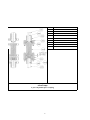
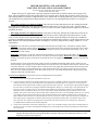
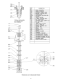
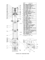
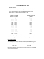
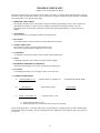
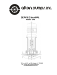
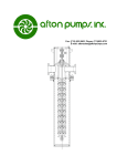
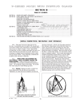
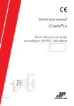
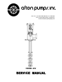
7335 Ave. N, P.O. Box 9426, Houston, Tx. 77261-9426
Fax: (713) 923-3902 Phone: (713)923-9731
E-mail: [email protected]
MODEL GSV
SERVICE MANUAL
SERVICE MANUAL
GENERAL
INTRODUCTION:
Afton pumps have been designed and tested to give dependable, trouble-free service with a minimum
amount of attention. To insure dependable operation the pump unit must be properly installed, operated and
serviced. Because of the variety of installations in which these pumps are used, this manual can only provide general
information. For specific information not contained in this manual contact an Afton dealer.
WARRANTY:
will be made for repairs or alterations unless made
with its written consent or approval. Afton Pumps
shall not be held responsible for work done,
apparatus furnished, or repairs made by others.
Warranty on equipment and accessories
produced by other manufacturers is limited to
warranty of the respective manufacturer.
Afton Pumps, Inc. warrants the equipment
of its manufacture against defects in material and
workmanship under normal use for a period of one
year after date of shipment. The Company’s
obligation under this warranty is limited, however, to
furnishing or repairing, without charge, F.O.B. its
factory, a similar part to replace any part of its
equipment which within one year from date of
shipment is found to have been defective at the time
it was shipped. The Purchaser must give Afton
Pumps immediate written notice upon finding such
defect. Afton Pumps shall have the option of
requiring the return of the defective material
transportation prepaid, to establish the claim. Afton
Pumps shall in no event be held liable for damages or
delay caused by defective material and no allowance
There are no warranties, expressed or
implied, except as stated in this warranty. Afton
Pumps shall not be liable for any special, indirect, or
consequential damages resulting in any manner from
the furnishing of this equipment or for any damages
of any kind arising from the use of this equipment.
-CAUTIONMotor for this unit is designed to operated in a vertical position. DO NOT attempt to transport,
install, or otherwise handle horizontally. Small motors, with grease lubricated bearings top and
bottom, that were mounted on the pump at the factory are an exception to this rule.
DO NOT attempt to install or operate without reading this manual.
DO NOT store this unit in an unprotected area. The unit was reasonably protected from field
damage and rust prior to shipment, but extended unprotected storage will cause problems
specifically in the coupling and mechanical seal areas.
DO CHECK for shipment damage and missing parts immediately upon receipt of equipment. All
shipments are F. O. B. shipping point.
1
TABLE OF CONTENTS
SUBJECT
PAGE
COVER
GENERAL WARRANTY INFORMATION
1
TABLE OF CONTENTS
2
GENERAL DESCRIPTION
Utility Service
Hydrocarbon Process Service
Chemical Handling
3
AFTON 4 PIECE ADJUSTABLE SPACER COUPLING
4
DRIVER MOUNTING AND ALIGNMENT
COUPLING INSTALLATION AND ADJUSTMENT
5
TYPICAL GSV CROSS-SECTION
6
GSV CROSS-SECTION
7
START-UP AND OPERATION
Check List
Start-Up
Lubrication
Operational Problems
8
WEAR RING AND SLEEVE BEARING CLEARANCES
9
TECHNICAL DATA SECTION
Bushing and Bearing Selection for Vertical Pumps
10
TROUBLE CHECK LIST
11
MODEL GSV GENERAL INSTALLATION
The Afton Model GSV general service vertical pump was designed by engineers experienced in vertical pump
design, operation, and repair to provide a rugged, simple machine capable of moving a wide variety of liquids from
open pits or closed sub surface vessels.
The following service classifications have construction features described available:
UTILITY SERVICE
For reasonable clean non-toxic, non-volatile liquids with slight corrosive characteristics and some lubricating
qualities. Pumps of this design for flow rates to 5000 gal/min. will be offered with cast iron discharge heads, vertical
hollow shaft drivers, packed stuffingboxes, steel column pipe, iron bowls, 416 shafts, bronze closed impellers and
bronze bearings. Flow rates above 5000 GPM are normally fitted with fabricated steel discharge heads. Lubrication
by pumpage.
HYDROCARBON PROCESS SERVICE
For reasonably clean liquids will be offered with fabricated steel discharge heads, iron bowls, bronze enclosed
impellers, bronze bearings, 416 shafts, and steel column pipe. Lubrication by pumpage. Drivers are vertical hollow
shaft with packed stuffingboxes or vertical solid shaft with spacer coupling when an optional mechanical seal is
required.
CHEMICAL HANDLING
Liquids with little or no lubricating qualities and moderate to high corrosive characteristics are handled by a basic
design having open impellers, carbon bearings, and properly selected corrosion resistant metallurgy. Discharge
heads for packed stuffing boxes are normally cast (to 5000 GPM) and fabricated when used with mechanical seals
and flow rates above 5000 GPM. All units with mechanical seals are furnished with spacer couplings.
Special modification for any of the above service groups may be required due to:
A. Liquids containing appreciable amounts of solids such as mill scale, sand, coke, or any other unusually dirty
services should be handled with oil lubricated column and open iron impellers. A fresh water or grease
injection to the bowl bearings is available, if desired, and speeds are reduced to extend life expectancy.
B. Vapor proof construction for volatile or toxic liquids utilizes single or double seals and gasketed head mounting
surface. This construction requires a fabricated discharge head and will prevent dangerous or unpleasant vapors
from escaping the sump and allow a vertical pump to deliver direct from a pressurized tank, if desired.
Afton experience has indicated the following design features are desirable and are, therefore, our standard:
Adjustable flanged couplings - when solid shaft drivers require the use of a coupling the obviously superior
flanged design is always used.
One piece shaft design with no line shaft couplings subject to corrosion, reverse rotation, and improper
assembly is standard for shaft lengths to 15', and is available for shafts to 20'.
Integral bearing cages manufactured with column and bearing cages welded and machined as one piece
positively prevents mis-assembly of these components.
Adequate down thrust to keep the shaft in tension and prevent vibration and shaft deflection in built into our
impeller design.
Flanged bowl assembly and column is standard on 10" and larger bowls and available but not normally
recommended on 6" and 8".
In addition to the above noted specific design features our flexibility of construction allowing cast or
fabricated discharge heads, open or closed impellers, pumpage or oil lubrication, flanged or bolted bowl
assemblies, and single or multi-stage construction with turbine, mixed flow, or propeller bowl assemblies
allow Afton to quickly ship the correct unit for your application for 5 to 50,000 GPM at 2' to 2000' TDH.
3
ITEM#
DESCRIPTION
002
MOTOR HUB COUPLING
003
PUMP SHAFT ADJUSTING NUT
004
SPACER COUPLING
005
PUMP SHAFT COUPLING HUB
203
PUMP SHAFT
283
COUPLING CAPSCREWS & NUTS
285
STRAIGHT KEY, PUMP & MOTOR
288
MOTOR CIRCULAR KEY
391
MOTOR
Afton Pumps
4- piece Adjustable Spacer Coupling
4
DRIVER MOUNTING AND ALIGNMENT
COUPLING INSTALLATION AND ADJUSTMENT
APPLYING TO ALL MODEL HPV, MPV AND GSV UNITS
HAVING SOLID SHAFT MOTORS
Pumps of this type are supplied with a split ring designed to transmit both up and down thrust from the pump to the
driver. This ring eliminates the need for pinning and/or set screwing the driver-coupling hub to the driver shaft. Units up to
and including 20 HP will normally be shipped with the motor mounted and no coupling adjustment required. All larger units
will normally have the pump and motor shipped separately. In this case, the coupling drawing should be reviewed prior to
assembly.
When pump and motor are shipped assembled, check the runout of the pump shaft between the coupling hub and the
drive collar. If it is within .002" T.I.R., proceed with installation and startup; if it exceeds .002" T.I.R., motor has shifted
during shipment or assembly has been damaged in some way. In this case, unbolt coupling and check alignment as described
in Method “B” below.
When pump and motor are shipped separately, set the motor on the pump. Normally the conduit box location can be
o
rotated in 90 increments, so position the conduit box as desired. Refer to the coupling drawing mentioned above. At this
point, it is left to the discretion of the millwright, the manner in which assembly should proceed. Obviously a 500 HP unit
operating at 3600 RPM would require a more precise alignment for optimum longevity than a a 10 HP unit operating at 1200
RPM. Therefore, the millwright should decide the desired degree of accuracy and proceed according to method “A” or “B”
outlined below.
A) Alignment: Secure the motor to the head with the motor hold-down bolts and tighten same. Assemble the coupling with the
adjusting nut in the proper relative position. Model HPV pumps should operate with a rotating element midway in the end play.
Model MPV pumps with enclosed impellers sizes 2"x3"x6" through 18"x20"x24" should operate approximately .050 to .100
from the bottom of the end play.
Model MPV pumps above 18"x20"x24" should operate approximately 3/4" from the bottom of the endplay. All Model MPV
pumps with open impellers should operate .020" to .030" above the bottom of endplay. Model GSV (same as MPV). Care
should be exercised at this time to be absolutely certain that the unit is not dragging after coupling is completely assembled and
tightened.
With the element correctly positioned and the coupling correctly assembled and tightened, tighten all drive collar set screws.
During assembly of the coupling, be sure all bolts and nuts are of the same size so no unbalance will be present. The drive collar
at this time should run 1/8" above the gland. Place an indicator stand on the pump head with the indicator button resting on the
o
pump shaft between the coupling hub and the drive collar. Rotate the shaft 360 several times. If the T.I.R. does not exceed
.002", the unit is suitable for operation. If the shaft runout exceeds .002", you should disassemble the coupling and proceed as
outlined in method “B” described below.
B) For an exact alignment or to locate the cause of a misalignment proceed as follows:
1)
Check the runout of the motor shaft. It should not exceed .001".
2)
Locate the motor in reference to the discharge head; this may be done by clamping an indicator on the motor shaft with a button
resting on an ID fit in the top of the discharge head. On the smaller size units where there is no cleanup cut, secure indicator to
o
motor hub and with the indicator button resting on pump shaft rotate motor shaft 360 . The runout may be appreciable but shifting
o
the motor in the correct direction will tend to eliminate this misalignment. When T.I.R. is within .005", rotate pump shaft 90 at a
o
o
time, three (3) times, stopping at each 90 point and checking alignment by rotating motor shaft 360 . Do not shift the motor
during these three (3) movements. However, it may be wise to make a simple sketch showing plus and minus points for each
quadrant. After you have done this you will note pump shaft is probably not in exact center of stuffingbox. However, by reviewing
your readings you will be able to determine how much and in what direction motor should be shifted to assure T.I.R. between
o
pump and motor shafts when both are rotated through 360 will not exceed .005. In other words, with the indicator clamped to the
motor shaft (or motor coupling hub) an indicator button resting on and reading from pump shaft, you should be able to rotate
o
o
motor shaft 360 four (4) times (when pump shaft is rotated at 90 intervals) with T.I.R. never exceeding .005". When this is
accomplished motor hold-down bolts should be tightened.
3)
At this point read and follow instructions in paragraph “A” above. As you assemble coupling, check runout of coupling hub O.D.
and faces to be sure no fits have been damaged in handling (O.D. runout should not exceed .002" and mating face runout should
not exceed .001").
NOTES:
Motor rotation should be checked before pump and motor is connected. Pump must not be under pressure during
impeller adjustment. Maximum and operating thrust on pumps of this type are normally down however, some
momentary up thrust can be expected.
5
TYPICAL GSV CROSS-SECTION
6
TYPICAL GSV CROSS-SECTION
7
MODEL GSV
START-UP AND OPERATION
Check List:
a.
Is motor properly lubricated?
b.
Is coupling on units with solid shaft motors properly installed, adjusted,
and tightened? Is head shaft nut on units with hollow shaft motors
properly adjusted?
c.
Is motor securely bolted down?
d.
Has motor rotation been checked? CAUTION...Do not check rotation
with unit coupled up and do not attempt to operate without checking
rotation.
e.
Is all piping connected and tightened?
f.
Does pump turn freely?
g.
Pumps fitted for oil lubrication must have the oil pot installed and filled.
You should allow the oil approximately 30 minutes of about 10 drops
per minute operation before starting pump.
h.
Are shut-down devices installed?
ix.
Is discharge pressure gauge installed?
j.
Are mechanical seal drive collar set screws (if so equipped) tight? Is
packing (if so equipped) installed, lubricated, and lightly tightened?
k.
Is adequate liquid actually visible in the pit?
Start-Up:
Crack open the discharge valve, push the starter button, and slowly open the discharge
valve while observing the discharge gauge. If a sudden drop in discharge pressure is
observed, shut the unit down, rapidly close the discharge valve and determine the cause.
When design discharge pressure is reached, immediately check current with an ammeter
and compare to nameplate amps. Allow the unit to operate until temperature and flow
rates have stabilized. (Minimum one (1) hour on larger units) before leaving unattended.
Lubrication:
None normally required by pump. Refer to motor manual for motor lubrication
information. Oil lube pumps see above.
Operational Problems:
If you feel that not all is in order, refer to trouble checklist on back page.
8
ENGINEERING DATA SECTION
Wear Ring Clearances:
The following data is in accordance with API 610 specifications and shall be considered
an Afton standard where applicable.
For cast iron, bronze, hardened 11 to 13 per cent chromium, and materials of similar
galling tendencies, the following running clearances shall be used:
Diameter of Rotating
Member at Clearance
(Inches)
Less than 2"
2.000" to 2.499"
2.500" to 2.999"
3.000" to 3.499"
3.500" to 3.999"
4.000" to 4.499"
4.500" to 4.999"
5.000" to 5.999"
6.000" to 6.999"
7.000" to 7.999"
8.000" to 8.999"
9.000" to 9.999"
10.000" to 10.999"
11.000" to 11.999"
Minimum Diametrical
Clearance
(Inches)
0.010"
0.011"
0.012"
0.014"
0.016"
0.016"
0.016"
0.017"
0.018"
0.019"
0.020"
0.021"
0.022"
0.023"
Generally speaking, a wear ring clearance should be renewed whenever the initial clearance is
doubled.
Materials with severe galling tendencies such as 18-8 stainless steel will require increased
clearances.
Sleeve Bearing Clearances:
Afton vertical pumps using pumpage lubricated sleeve bearings and throat bushings of bronze or
carbon running against steel, 416, or 18-8 shafts (or shaft sleeves) shall have the following running
clearances:
Diameter of rotating member
Clearances
.075 to 1.500
.004" to .006"
1.500 to 2.500
.006" to .008"
Pumps repaired under Afton’s supervision are to have clearances renewed to above specifications
when initial clearance is doubled.
9
TECHNICAL DATA SECTION
Bushing and Bearing Selection for Vertical Pumps
The following materials are available for consideration as interstage and lineshaft
bearings on Afton Model GSV, MPV, and HPV pumps and stuffingbox bushings on
Model ILVS In-Line pumps:
Bronze
Use whenever possible. Do not use on any corrosive service unless pump is all
o
o
bronze. Do not use above 200 F or below –20 F without Engineering
Department approval. Do not use on sandy well water. Do not use on dirty
water sump service.
Carbon
Second choice after bronze. Use when corrosive products prelude the use of
bronze and product lubricity is low; for example, propane containing
o
hydrogen sulfide. Do not use unless pumpage is clean. Use below –20 F.
Remember the coefficient of thermal expansion is practically zero.
Iron
Use on mildly corrosive service: for example, sour crude. Use for
o
temperatures above 200 F. Use where particles in the product prelude the use
of carbon. Use only on products with fair or better lubricity.
Rubber
Applicable only to Model GSV pumps and water wells. Use in conjunction
with open impeller on sandy well water or dirty sump service. Do not use in
hot service or where any product detrimental to neoprene is present.
Teflon, glass filled or otherwise
Use only at customer’s insistence and with
management approval. Suggest carbon for most
services where Teflon is specified.
For simplicity we are referring to the materials by their most common name. We
are not using trade names or compositions, but please note each material has
components added to improve its suitability as a bearing material.
10
TROUBLE CHECK LIST
(Applies to All Afton Model GSV Pumps)
Should you feel the pump is not doing the job for which it was sold a few simple checks and observations will help
locate the trouble. To make these checks you will need a pressure gauge, located at the pump discharge, an ammeter,
and a performance curve applying to the pump.
1) IMPELLER ADJUSTMENT
The impeller should run close to the bottom of the bowl assembly, approximately .020" to .040" clearance for
open impellers and .040" to .080" for closed. Complete instructions for setting this clearance are in the
installation section of this booklet. Units above 18x24 should operate approximately ½" up from bottom of
endplay
2) ALIGNMENT
Does unit rotate freely? Is alignment within specified tolerances?
3) ROTATION
Unit rotation must be Counter Clockwise (CCW) looking down on motor.
4) NOISE & VIBRATION
Does pump have either at operating point and/or shut-off?
(If so, do not operate until these conditions are corrected).
5) VORTEXING
Are whirlpools observed near pump suction? Check required submergence.
6) NPSH
Is pumpage temperature above ambient? Is pump suction clogged?
7) DISCHARGE PRESSURE & AMPERAGE
Check both with discharge valve closed, one-half open, and fully open.
8) VOLTAGE
Is it within approximately 10% of design? Is motor, wired correctly?
9) CORRELATE READINGS
A)
Discharge PSIG x 2.31
Pumpage specific gravity
+ Distance Down To Liquid Level
B)
Operating H.P.
Motor Nameplate H.P.
approximately equals
C)
T.D.H. x Gal. Per Min. (2)
3960 x Pump Eff. (1)
x Specific Gravity = H.P.
= Total Differential Head (TDH)
Amp Readings
Full Load Amps
1) From pump Performance Curve
2) Read from pump curve and estimate with various valve openings
If after checking the above, you still feel the pump is not performing as it should, prepare to remove and dismantle.
Should pump still be in warranty. AFTON would appreciate the opportunity of discussing the unit with you prior to
its removal.
11