1
WORKSHOP
INSTRUCTION
MANUAL
ALL MODELS, 1957-1964
MATCHLESS
MOTOR
Plumstead Road
London . S.E.18
England
CYCLES
LIMITED
CONTENTS
PAGE
TABLE OF MODELS
…
…
…
…
…
…
…
…
…
…
…
…
…
…
…
3
TECHNICAL DATA
…
…
…
…
…
…
…
…
…
…
…
…
…
…
…
4
SECTION A
…
…
…
…
…
…
…
…
…
…
…
10
ENGINE AND LUBRICATION
GEARS AND GEAR BOX
”
B
…
…
…
…
…
…
…
…
…
…
…
48
FORKS
”
C
…
…
…
…
…
…
…
…
…
…
…
57
FRAME
”
D
…
…
…
…
…
…
…
…
…
…
…
63
WHEELS AND BRAKES
”
E
…
…
…
…
…
…
…
…
…
…
…
65
TRANSMISSION
”
F
…
…
…
…
…
…
…
…
…
…
…
74
CARBURETTER
”
G
…
…
…
…
…
…
…
…
…
…
…
76
ELECTRICAL
”
H
…
…
…
…
…
…
…
…
…
…
…
78
…
…
…
…
…
…
…
…
…
…
…
78
TOOLS
APPENDIX
…
FOREWORD
THIS MANUAL has been compiled as a practical guide to enable service staff and private owners alike to
undertake overhauls and repairs, in the sequence as applied by the factory service department.
In contrast to the orthodox service manual, the possible faults, engine noises and also lubrication troubles
are detailed, to enable the operator to readily diagnose the source and cause of the trouble, thus saving work
hours and possibly unnecessary fitting of new parts.
Dismantling instructions are given step by step, in short paragraphs, obviating prolonged and confusing
reading matter.
Whenever possible, figures shown in parenthesis, or part numbers are quoted in the text for reference to the
subject depicted, and so enable the operator to determine the location and application of any part described.
Where suitable instruments are available to measure engine and gear box parts, reference should be made
to technical data for normal dimensions.
Elementary details such as valve grinding are covered in the
handbook issued with each new machine.
2
TABLE OF MODELS DESCRIBED
HEAVYWEIGHT MODELS
LIGHTWEIGHT MODELS
1957
350 cc.
350 cc.
350 cc.
500 cc.
500 cc.
500 cc.
600 cc.
…
…
Trials …
Scrambler
…
…
Scrambler
Twin
…
Twin
…
…
…
…
…
…
…
…
…
…
…
…
…
…
…
G3 LS
G3 C
G3 LCS
G80 S
G80 CS
G9
G11
Models
16 MS
16 MC
16 MCS
18 S
18 CS
20
30
1958-1959
250 cc. …
…
250 cc. Scrambler
…
…
… G2
… G2 CS
1960-1962
250 cc. …
…
250 cc. Scrambler
350 cc. …
…
…
…
…
Models
14&14 S
… G2 & G2 S
14 CS
… G2 CS
8
… G5
1958
350 cc.
350 cc.
350 cc.
500 cc.
500 cc.
500 cc.
600 cc.
600 cc.
…
…
Trials …
Scrambler
…
…
Scrambler
Twin
…
Twin
…
Twin
…
…
…
…
…
…
…
…
…
…
…
…
…
…
…
…
…
G3 LS
G3 C
G3 LCS
G80
G80 CS
G9
G11
G11 CS
Models
16 MS
16C
I6CS
18
18 CS
20
30
30 CS
1962
…
… G2 CSR
…
…
Models
14
&
CSR
…
… G2 & CSR
1959
350 cc.
350 cc.
500 cc.
500 cc.
600 cc.
500 cc.
500 cc.
500 cc.
650 cc.
650 cc.
650 cc.
…
…
Trials …
…
…
Scrambler
Scrambler
Twin …
Twin …
…
Twin
Twin …
Twin …
Twin …
…
…
…
…
…
…
…
…
…
…
…
…
…
…
…
…
…
…
…
…
…
…
G3
G3 C
G80
G80 CS
TCS
G9
G9 CSR
G9 CS
G12
G12 CSR
G12 CS
20
20 CSR
20 CS
31
31 CSR
31 CS
…
…
…
…
…
…
…
…
…
…
…
…
…
…
…
…
…
…
Models
G3
16
G3 C
16 C
G80
18
G80 CS
18 CS
TCS
20
G9
G12
31
G12 CS
31 CS
G12 CSR
31 CSR
1962
350 cc.
350 cc.
500 cc.
500 cc.
600 cc.
650 cc.
650 cc.
…
…
…
…
…
…
…
…
…
…
…
…
…
…
G 3 G3 S
G3 C
G80
G80 CS
TCS
G12
G12 CSR
…
…
…
…
…
…
…
…
…
…
…
…
16
G3
18
G80
G80 CS
Twin
(Short stroke)
Trials …
…
…
Scrambler
Scrambler
Twin …
Twin
…
1963-1964
350 cc. …
350 cc. …
500 cc. …
500 cc. …
500 cc. …
650 cc. …
1963-1964
250 cc. …
250 cc. …
Models
16
16 C
18
18 CS
1960-1961
350 cc. …
…
350 cc. Trials …
500 cc. …
…
500 cc. Scrambler
600 cc. Scrambler
500 cc. Twin
…
…
650 cc. Twin
…
650 cc. Twin
650 cc. Twin …
Models
16 & 1 6 S
16 C
18
18 CS
31
31 CSR
Models
…
…
…
…
…
…
…
3
…
…
…
Models
14
14 CS
14 CSR
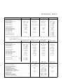
TECHNICAL DATA
250 cc. and Sports
250 cc. Scrambler
350 Lightweight
350 Heavyweight
2.7197—2.7187
7.4
2.718—2.7172
.008"—.013"
7
/ 8 " —.00025"
7
/ 8 " —.00075'
H 1.7037
L 1.7035
H 1.20375
L 1.20350
¼ x ¼ (30)
2.5/64"
.168"
l x 2½ x ¾
l x 2¼ x 5/8
H 1.1255
L 1.1250
½ +.0005
½ –.0005
5
/ 8 +.00075
5
/8 –.00075
Cylinder bore size
…
…
Compression ratio
Piston skirt diameter TOP
Piston ring gap …
…
Gudgeon pin bush
…
…
…
…
…
…
…
…
…
…
…
2.7513—2.7503
7.8
2.7429—2.7421
.008"—.012"
.7505—.7508
2.7513—2.7503
10.5
2.7429—2.7421
.008"—.012"
as 250
2.835—2.834
6.9
2.8286—2.8276
.008"—.013"
as 250
Con rod diameter
…
…
…
2.016—2.01575
2.016—2.01575
Crank pin diameter
…
…
…
1.516—1.5158
1.516—1.5158
…
Crank pin rollers
Valve spring free length
Valve spring wire diameter
…
Drive side bearing
…
Drive side bearing
Timing side bush
…
…
…
…
…
…
…
…
…
…
…
…
…
H 1.7037
L 1.7035
H 1.20375
L 1.20350
¼ x ¼ (20)
1.53/64"
.176"
7
/8 x 2 x 9/16
¼ x ¼ (28)
1.43/64"
3/16"
7
/8 x 2 x 9/16
¼ x ¼ (28)
1.53/64"
.176"
7
/8 x 2 x 9/16
Cam wheel bushes (all)
…
…
H .8755
L .8750
H .8755
L .8750
H .8755
L .8750
Rocker box bushes (all)
…
…
NOTE: Technical details given for the 250 cc. Scrambler apply also to the 250 cc. C.S.R. model with the exception of the compression ratio which is 8 to 1.
Finished cylinder bore size 1964 350 (2.835"—2.834') 500 (3.387"—3.386") 350 trials (2.835"—2.834")
…
Cylinder bore size
…
Compression ratio
Piston skirt diameter TOP
…
Piston ring gap …
Gudgeon pin bush
…
…
…
…
…
…
…
…
…
…
…
Con rod diameter
…
…
…
Crank pin diameter
…
…
…
Crank pin rollers
…
Valve spring free length
Valve spring wire diameter
Drive side bearing
…
…
Drive side bearing
…
Timing side bush
…
…
…
…
…
…
…
…
…
…
…
…
* 1962 ¼ x ¼ (28)
Cam wheel bushes
…
…
Rocker box bushes
Cylinder bore size
…
…
…
…
(all)
350 Short Stroke
500 Heavyweight
500 Scrambler
600 Scrambler
2.915—2.914
8.5
2.9063—2.9055
.008"—.013"
7
/ 8 "—.00025"
7
/ 8 "—.00075"
H 1.7037
L 1.7035
H 1.20375
L 1.20350
¼ x ¼ (30)
1 17/32
3
/16"
l x 2½ x ¾
l x 2¼ x 5/8
H 1.1255
L 1.1250
3.2505—3.2495
7.3
3.2475—3.2467
.010"—.015"
as 350
3.386—3.385
8.7
3.3795—3.7870
.010"—.015"
as 350
3.5005—3.4995
9.2
3.492—3.491
.012"—.016"
as 350
H 1.7037
L 1.7035
H 1.20375
L 1.20350
¼ x ¼ (30)
2 5/64"
.168"
l x 2½ x ¾
l x 2¼ x 5/8
H 1.1255
L 1.1250
H 2.016
L 2.01575
H 1.5156
L 1.5154
½ x ¼ (14)*
1 17/32"
3
/16"
l x 2½ x ¾
l x 2¼ x 5/8
H .8757
L .8752
H 2.016
L 2.01575
H 1.5156
L 1.5154
¼ x ¼ (28)*
1 17/32"
3
/16"
l x 2½ x ¾
l x 2¼ x 5/8
H .8757
L .8752
500 cc. Twin
600 cc. Twin
650 cc. Twin
2.598" +.0005"
–.0015
7 to l
8 to 1
2.5933"—2.5925"
.006"
All
2.835"—2.834"
2.836"—2.835"
7 to 1
8 to 1
2.8341"—2.8334"
.006"
.7499—.7497
.7505—.7500
1.62575—1.62525
1.62675—1.62625
3 x l 3/8 x 11/16
0.8125"—0.8135"
0.500"—0.501"
0.7485"—0.7490"
0.7495"—0.7502"
0.373"—0.374"
7.5
8.5
2.8295"—2.8287"
.006"
All
½" x.0005"
½" –.0005"
5
/ 8 " x.00075"
5
/ 8 " –.00075"
(all)
…
…
…
…
…
…
…
Compression ratio Std.
…
Compression ratio Sports
…
Piston skirt diameter Top
…
…
…
Piston ring gap
…
…
Gudgeon pin diameter
…
Gudgeon pin rod diameter
Crankshaft diameter (crankpin) …
Crankshaft diameter (centre bearing)
…
Crankshaft bearings (2 off)
…
…
…
Camshaft bushes
…
…
…
Rocker bushes
…
Intermediate shaft diameter
…
Intermediate bush diameter
…
Cam follower spindle diameter
…
…
…
…
…
…
…
…
…
…
…
…
…
…
…
…
…
…
…
…
…
…
…
…
…
…
…
…
…
…
…
…
…
…
…
…
…
…
…
…
…
…
…
…
…
…
…
…
…
…
…
…
…
…
…
…
”
”
3”
3 x l /8 x 11/16
All
”
”
”
”
4
”
”
3”
3 x l /8 x 11/16
All
”
”
”
”
CARBURETTER SPECIFICATIONS
Carburetter type
Bore size …
…
Main jet
Main jet (air filler)
…
Slide
…
Pilot jet
Needle jet …
Needle location
Carburetter type
Bore size …
…
Main jet
Main jet (air filter)
…
Slide
…
Pilot jet
Needle jet …
Needle location
Model:
Carburetter type
…
Bore size
…
Main jet
Main jet (air filter)
…
Slide …
…
Pilot jet
…
Needle jet
Needle location
…
…
…
…
…
…
…
Model:
…
…
…
…
…
…
…
…
…
…
…
…
…
…
…
…
Model:
…
…
…
…
…
…
…
…
…
…
…
…
…
…
…
…
…
…
…
…
…
…
…
…
…
…
…
…
…
…
…
Model:
Carburetter type
…
…
…
Bore size
Main jet …
…
…
Main jet (air filter)
…
…
…
…
Slide
Pilot jet …
…
…
Needle jet
…
…
Needle notch location …
Model:
…
Carburetter type
…
…
Bore size
…
…
Main jet …
Main jet (air filter)
…
Slide
…
…
…
Pilot jet …
…
…
…
…
Needle jet
Needle notch location …
…
…
…
…
…
…
…
…
1957 Models
350 cc. OHV
…
376/5
…
1 1/16"
…
220
210
…
…
3½
…
30
…
.106
…
central
500 cc. OHV
389/1
1 5/32"
260
250
3½
30
.106
central
500 cc. Twin
376/6
1"
240
230
4
30
.106
central
600 cc. Twin
376/78
1 1/16"
280
270
3½
30
.106
central
…
…
…
…
…
…
…
…
1958 Models
350 cc. OHV
…
376/5
…
1 1/16"
…
210
…
200
…
3½
…
30
…
.106
…
central
500 cc. OHV
389/1
1 5/32"
260
250
3½
30
.106
central
500 cc. Twin
376/6
1"
220
210
4
30
.106
central
600 cc. Twin
376/78
1 1/16"
280
270
3½
30
.106
central
1959 Models
500 cc. Twin
500 cc. OHV
376/6
389/1
1"
1 5/32"
260
220
250
210
4
3½
30
30
.106
.106
central
central
500 cc. CS.
376/6
1"
220
210
4
30
.106
central
650 cc. Twin
389/49
1 1/8"
400
380
3
30
.106
central
650 cc. C.S.R.
389/22
1 1/8"
430
400
3½
30
.106
central
…
…
…
…
…
…
…
…
1960 Models
350 cc. OHV 500 cc. OHV
389/1
376/5
1 5/32"
1 1/16"
210
260
200
250
3½
3½
30
30
.106
.106
central
central
500 cc. Twin
376/6
1"
220
210
4
30
.106
central
650 cc. Twin
389/18
1 1/8"
390
340
4
20
.106
4th
650 cc. C.S.R.
389/22
1 1/8"
450
390
4
20
.106
4th
…
…
…
…
…
…
…
…
1961-1962 Models
350 cc. OHV 500 cc. OHV
389/52
376/5
1 5/32"
1 1/16"
210
300
200
300
3½
3½
30
25
.106
.106
central
central
500 cc. Twin
376/209
1"
200
180
4
25
.106
central
650 cc. Twin
389/50
1 1/8"
390
340
4
20
.106
4th
650 cc. C.S.R.
389/49
1 1/8"
450
390
4
20
.106
4th
250 cc. OHV
376/99
1 1/16"
180
180
3½
25
.106
central
350 cc. OHV
389/42
1 1/8"
220
220
3
25
.106
central
250 cc. C.S.R.
389/82
1 1/8"
200
200
3
20
.106
central
…
…
…
…
…
…
…
…
…
…
…
…
…
…
…
…
…
…
…
…
…
…
…
…
…
…
…
…
…
…
…
…
350 cc. OHV
376/5
1 1/16"
210
200
3½
30
.106
central
…
…
…
…
…
…
…
…
…
…
…
…
…
…
…
…
…
…
…
…
…
…
…
…
…
…
…
…
…
…
…
…
…
…
…
…
…
…
…
…
Lightweight Models (1959-1962)
…
Carburetter type
…
…
Bore size
…
…
Main jet
…
Main jet (air filter)
…
…
Slide …
…
…
Pilot jet
…
…
Needle jet
Needle notch location
…
…
…
…
…
…
…
…
Model:
…
…
…
…
…
…
…
…
…
…
…
…
…
…
…
…
…
…
…
…
…
…
…
…
…
…
…
…
…
…
…
…
…
…
…
…
…
…
…
…
5
…
…
…
…
…
…
…
…
…
…
…
…
…
…
…
…
Model:
Carburetter type …
Bore size …
…
…
…
Main jet
Main jet (air filter)
Slide
…
…
…
…
Pilot jet
Needle jet …
…
Needle notch location
…
…
…
…
…
…
…
…
Carburetter type …
Bore size …
…
Main jet
…
…
Main jet (air filter)
Slide
…
…
…
…
Pilot jet
Needle jet …
…
Needle notch location
…
…
…
…
…
…
…
…
Front
Rear
Magneto
Dyno
Front
Rear
Magneto
Dyno
…
…
…
…
…
…
…
…
…
Front
…
Rear
Magneto …
…
Front
Rear
…
Magneto …
…
…
…
…
…
…
…
…
…
…
…
…
…
…
…
…
…
…
…
…
…
…
…
…
…
…
…
…
Trial and Scrambler Models (1959-1962)
250 cc. Scrambler 350 cc. Trials 500 cc. Scrambler 500 cc. Scrambler 600 cc. Scrambler
376/276
376/59T
Monobloc
T5GP
T5GP
…
1 3/8"
…
1 3/16"
1 1/16"
1 1/16"
1 3/8"
…
450
230
290
210
320
430
200
—
—
—
…
3
7
3
7
…
3½
…
30
25
—
30
—
.106
.106
—
.107T
—
…
central
central
central
central
—
…
350 cc. Short Stroke 1962
389/68
…
…
…
…
…
…
…
…
1 1/8"
230
…
…
…
…
…
…
…
…
230
3.5
…
…
…
…
…
…
…
…
25
.106
…
…
…
…
…
…
…
…
central
350 cc.
TABLE OF CHAINS
Chain sizes (Heavyweight Model)
Front chain
+.305"
…
…
… ½"
…
…
… 5/8" +.380"
Rear chain
3
…
… / 8 " +.225"
Magneto chain …
…
…
… 3 / 8 " +.225"
Dyno chain
1957 Models
350 cc.
500 cc.
Scrambler 500 cc. Twin 600 cc. Twin 650 cc. Twin
Trials
500 cc.
C.S.R.
67 links
98 „
46 „
50 „
66 links
97 „
46 „
50 „
350
cc.
350 cc.
Trials
67 links
68 links
67 links
68 links
97 „
98 „
97 „
97 „
46 „
46 „
50 „
50 „
1958 Models
500 cc.
Scrambler 500 cc. Twin 600 cc. Twin 650 cc. Twin
500 cc.
C.S.R.
67 links
98 „
46 „
50 „
66 links
97 „
46 „
50 „
350 cc.
350 cc.
Trials
67 links
68 links
68 links
67 links
98 „
97 „
97 „
97 „
46 „
46 „
50 „
50 „
1959 Models
500 cc.
Scrambler 500 cc. Twin 600 cc. Twin 650 cc. Twin
500 cc.
C.S.R.
67 links
98 „
66 links
94 „
46 „
350 cc.
350 cc.
Trials
67 links
98 „
66 links
94 „
46 „
Front
Rear
…
…
…
…
…
…
…
…
Front
Rear
…
…
…
…
…
…
…
…
Front
Rear
…
…
…
…
…
…
…
…
68 links
98 „
67 links
97 „
46 „
1960-1962 Models
500 cc.
Scrambler
500 cc.
69 links
98 „
67 links
98 „
67 links
97 „
500 cc. Twin 600 cc. Twin 650 cc. Twin
67 links
97 „
Chain sizes (Lightweight Models)
Front chain
…
…
… 3/8" +.225"
Rear chain
…
…
… ½" +.305"
Front Scrambler
…
… ½" +.225"
1959-1962 Models
250 cc. and Sports
250 cc. Scrambler
72 links
55 links
123 „
131 „
Late 1962 Models
250 c.c. Scrambler
250 cc. and Sports
72 links
72 links (3/8" + .225")
123 „
133 „
1962 C.S.R. Models
250 cc. and Sports
250 cc. Scrambler
72 links (.315" x .625" Duplex)
123 „ (½" x .305")
6
68 links
97 „
68 links
97 „
350 cc.
72 links
123 „
350 cc.
72 links
123 „
350 cc.
67 links
97 „
C.S.R.
67 links
97 „
SCRAMBLES MODELS 1957
Gear Ratios.
First
Second
gear
gear
… 2.67
1.77
Internal Ratios
First
Sprocket
Second
gear
Engine
size
gear
(A)
(B)
(A)
(B)
Third
gear
1.35
Third
gear
18.39 to 1 12.19 to 1 9.30 to 1
16 teeth
17.30 to 1 11.47 to 1 8.74 to 1
17 „
16.34 to 1 10.83 to 1 8.26 to 1
18 „
15.48 to 1 10.26 to 1 7.83 to 1
19 „
14.71 to 1 9.75 to 1 7.43 to 1
20 „
14.01 to 1 9.29 to 1 7.08 to 1
21 „
13.37 to 1 8.86 to 1 6.76 to 1
22 „
(A) Standard for 350 cc. Scrambles Models.
(B) Standard for 500 cc. Scrambles Models.
TRIALS MODELS
Gear Ratios.
First
Second
gear
gear
… 3.28
Internal Ratios
2.39
First
Second
Sprocket
gear
Engine
size
gear
GEAR BOX RATIOS, 1957 and 1958 TWINS
to 1959
Third
gear
1.47
Third
gear
22.59 to 1 16.46 to 1 10.12 to 1
16 teeth
17 „
standard 21.25 to 1 15.48 to 1 9.52 to 1
18 „
20.07 to 1 14.62 to 1 8.99 to 1
19 „
19.02 to 1 13.86 to 1 8.52 to 1
20 „
18.07 to 1 13.16 to 1 8.10 to 1
17.22 to 1 12.54 to 1 7.71 to 1
21 ,,
22 „
16.43 to 1 11.97 to 1 7.36 to 1
(A) Standard for 350 cc. Trials Models.
(B) Standard for 500 cc. Trials Models.
Sprocket sizes.
…
…
…
… 42 teeth
Clutch
Gear box …
…
…
… 16 „
…
…
… 42 „
Rear wheel
Fourth
gear (top)
1.1
Fourth
gear (top)
6.89 to
6.48 to
6.l2 to
5.80 to
5.51 to
5.25 to
5.01 to
Engine
(A)
(B)
1
1
1
1
1
1
1
Sprocket
size
First
gear
Third
gear
Second
gear
7.83
15.48
10.26
19 teeth
7.43
14.71
9.75
20 „
7.08
14.01
9.29
21 „
6.76
13.37
8.86
22 „
6.46
12.78
8.47
23 „
(A) Standard 500 cc. Engine sprocket.
(B) Standard 600 cc. Engine sprocket.
Gear box internal ratios.
First
Second
Third
gear
gear
gear
2.67 to 1
1.77 to 1
Fourth
gear (top)
5.80
5.51
5.25
5.01
4.79
Fourth
gear (top)
1.35 to 1
1 to 1
Sprocket sizes.
…
…
… 42 teeth
Clutch
Gear box …
…
… 16 „
Rear wheel …
…
… 42 „
Fourth
gear (top)
1.1
Fourth
gear (top)
HEAVYWEIGHT GEAR RATIOS
6.89 to 1
Engine
6.48 to 1
6.12 to 1
5.80 to 1
5.51 to 1
5.25 to 1
5.01 to 1
(A)
(C)
(B)
Single cylinder Models (1957-1962)
Sprocket
Second
Third
First
size
gear
gear
gear
Fourth
gear (top)
17 teeth
16.6 to 1 11.05 to 1 7.91 to 1
18 „
15.65 to 1 10.39 to 1 7.46 to 1
19 „
14.85 to 1 9.86 to 1 7.07 to 1
20 „
14.11 to 1 9.37 to 1 6.73 to 1
21 „
13.42 to 1 8.93 to 1 6.41 to 1
22 „
12.81 to 1 8.52 to 1 6.11 to 1
(A) Standard for 350 cc. Touring Models.
(B) Standard to 500 cc. Touring Models.
(C) S/C Engine Sprocket.
6.48 to 1
6.12 to 1
5.80 to 1
5.51 to 1
5.25 to 1
5.01 to 1
TWIN CYLINDER MODELS 1959-1962
250 cc. SCRAMBLES MODELS, 1959 to 1960
Gear Ratios.
Second
Fourth
First
Third
gear
gear
gear (top)
gear
… 2.92 to 1 1.85 to 1 1.30 to 1
Internal Ratios
1 to 1
Gear Ratios with 17 teeth Engine Sprocket.
First gear Second gear Third gear Top gear
23.4 to 1 14.8 to 1 10.4 to 1
8.0 to 1
Sprocket sizes
…
…
…
… 46 teeth
Clutch
Gear box …
…
…
… 17 „
…
…
… 73 „
Rear wheel
Engine
(C)
(A)
(B)
Sprocket
size
Gear Ratios.
Second
First
gear
gear
Third
gear
9.86
19 teeth
7.07
14.85
9.37
20 „
6.73
14.11
8.93
21 „
6.41
13.42
8.52
22 „
6.11
12.81
8.15
23 „
5.85
12.23
(A) Standard 500 cc. Engine Sprocket.
(B) Standard 650 cc. Engine Sprocket.
(C) S/C Engine Sprocket 500 cc.
(A) S/C Engine Sprocket 650 cc.
Gear ratios Models C S . and C.S.R.
First
Second
Third
gear
gear
gear
250 cc. SCRAMBLES MODELS, 1961 to 1962.
Gear Ratios.
First gear Second gear Third gear Fourth gear
(top)
Internal Ratios 2.42 to 1
1.85 to 1
1.30 to 1
1 to 1
Gear Ratios with 17 teeth Engine Sprocket.
First gear Second gear Third gear Fourth gear
(top)
21.62 to 1 16.6 to 1
11.63 to 1
8.95 to 1
11.51 to 1
Location
…
Clutch
*Gearbox …
Rear wheel
* 17 teeth
350 cc. LIGHTWEIGHT MODELS, 1960 to 1962
ALSO 250 cc. C.S.R. MODEL
Gear Ratios.
First gear Second gear Third gear Fourth gear
(top)
Internal Ratios 2.92 to 1
1.85 to 1
1.30 to 1
1 to 1
Gear Ratios with 22 teeth Engine Sprocket.
First gear Second gear Third gear Fourth gear
(top)
18.68 to 1 11.82 to 1
8.32 to 1
6.39 to 1
Sprocket sizes.
…
…
…
… 46 teeth
Clutch
Gear box …
…
…
… 18 „
…
…
… 55 „
Rear wheel
5.49 to 1
7.65 to 1
Fourth
gear (top)
4.5 to 1
Number of teeth
42
16 or 17
42
used on C.S.R. Models.
…
…
…
2.56 to 1
7
5.80
5.51
5.25
5.01
4.79
Sprockets.
…
…
…
…
…
…
Gear box ratios (internal).
First
Second
Third
gear
gear
gear
Front
„
„
„
Fourth
gear (top)
1.70 to 1
Chain sizes.
…
Front (all Models) …
…
…
Rear (all Models)
Chain length.
350 Single
67 links
Rear
500 Single
69 „
„
500 Twin
67 „
„
650 Twin
68 „
1.22 to 1
Fourth
gear (top)
1 to 1
… ½ " by . 3 0 5 "
… 3/8" by 5/8"
350 Single 98 links
500 Single 98 „
All Twins 97 „
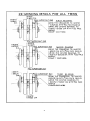
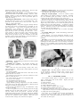
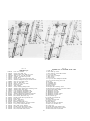
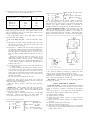
1959-62 ALL TWINS MODELS
37°
1957-58 ALL TWIN MODELS
24°
TDC .
T.D.C.
OPENS
OPENS
CLOSES
CLOSES
77°
65°
BDC
B.D.C.
INLET VALVE TIMING
TDC
INLET VALVE TIMING
43°
T.D.C
.
25°
CLOSES
CLOSES
OPENS
OPENS
73°
B.DC.
B.D.C.
EXHAUST VALVE TIMING
63°
EXHAUST VALVE TIMING
1957-62 HEAVEYWEIGHT MODELS (350-500 cc)
36°
TDC .
INLET VALVE TIMING 3 5 0 c c .
OPENS
18°
CLOSES
T.D.C.
OPENS
51°
T.D.C.
B.D.C.
30°
CLOSES
CLOSES
69°
B.D.C.
INLET VALVE TIMING
500cc
OPENS
B.D.C.
50°
EXHAUST VALVE TIMING ALL 350
& 500cc TOURING
8
1959-62 LIGHTWEIGHT MODELS
40°
1956-62 HEAVYWEIGHT SCRAMBLERS
T.D. C .
T.D.C.
59°
INLET VALVE TIMING 1956-59
OPENS
OPENS
CLOSES
CLOSES
T.D.C.
67°
75°
B.D.C.
69°
OPENS
B.D.C.
INLET VALVE TIMING
CLOSES
40°
T.D.C.
T.D.C.
48°
CLOSES
81°
CLOSES
B.D.C.
INLET VALVE TIMING 1960-62
OPENS
B.D.C.
OPENS
70°
69°
B.D.C
EXHAUST VALVE TIMING 1956-62
EXHAUST VALVE TIMING
1950-64 TWIN MODELS
FITTED WITH 'SPEED -KIT' CAMS RUN WITH ·012 CLEARANCE
1957-62 TRIALS MODELS (350cc)
26°
20°
TDC,
T.D.C.
OPENS
OPENS
CLOSES
CLOSES
55°
53°
B.D.C.
INLET VALVE TIMING
T.D.C.
B.D.C.
INLET VALVE TIMING WITH ·020" CLEARANCE
T.D.C.
25°
20°
CLOSES
CLOSES
OPENS
B.D.C.
OPENS
B.D.C.
64°
EXHAUST VALVE TIMING
55°
EXHAUST VALVE TIMING WITH ·020" CLEARANCE
9
LUBRICANTS TO USE.
Efficient lubrication is of vital importance and it is false economy
to use cheap oils and greases.
We recommend the following lubricants to use in machines of our
make.
PERIODICAL MAINTENANCE
Regular maintenance attention to lubrication and certain adjustments must be made to ensure unfailing reliability and satisfactory
service.
DAILY
Oil reservoir
FOR ENGINE LUBRICATION
EXTREME COLD
above 50° F
32° F to 50° F
below freezing point
(32° F)
SAE 50
SAE 30
SAE 20
Mobiloil D
Castrol Grand Prix
Energol SAE 50
Essolube 50
Shell X-100 Motor Oil
50
Regent Havoline 50
Mobiloil A
Castrol XL
Energol SAE 30
Essolube 30
Shell X-100 Motor
Oil 30
Regent Havoline 30
Mobiloil Arctic
Castrolite
Energol SAE 20
Essolube 30
Shell X-100 Motor
Oil 20/20W
Regent Havoline 20
HOT
COLD
Petrol tank
Inspect oil level and lop-up if necessary. Check
oil circulation.
Check level and refill if necessary.
Oil reservoir
Tyres
Check level and lop-up if necessary.
Check pressures and inflate if necessary.
WEEKLY
EVERY 500 MILES (800 KILOMETRES)
Oil reservoir
Drain at first 500 miles and re-fill with new oil, and
clean filters.
Check contact breaker points. Regrease fell pad.
Drain at first 500 miles and re-fill.
Check level of oil when machine is standing vertically on level ground.
Inspect each cell for level of electrolyte and top up
with distilled water if necessary. Level of electrolyte should just be over top of plates. Beware of
overfilling.
Ignition
Gear box
Chaincase
Note: For the British Isles and much of Europe the Cold and Hot
recommendations approximate to Winter and Summer conditions respectively. The Extreme Cold recommendations refer
to wintry conditions in parts of Northern Europe, Canada, the
Baltic and Scandinavian countries, and high mountainous
districts where extreme cold is the average condition.
Battery
EVERY 1,000 MILES (1,600 KILOMETRES)
Oil reservoir
Rear chain
Gear box
Small parts
FOR GEAR BOX LUBRICATION
HOT
COLD
above 50° F
32° F to 50° F
below freezing point
(32° F)
SAE 50
SAE 50
SAE 30
Mobiloil D
Castrol Grand Prix
Energol SAE 50
Essolube 50
Shell X-100 Motor Oil
50
Regent Havoline 50
Mobiloil D
Castrol Grand Prix
Energol SAE 50
Essolube 50
Shell X-100 Motor
Oil 50
Regent Havoline 50
Mobiloil A
Castrol XL
Energol SAE 30
Essolube 30
Shell X-100 Motor
Oil 30
Regent Havoline 30
EXTREME COLD
Chaincase
EVERY 2,000 TO 5,000 MILES (3,200 TO 8,000 KILOMETRES)
Air
(according to road conditions).
(If fined) clean and re-oil filler element.
filter
EVERY 3,000 MILES (4,800 KILOMETRES)
Rear chain
Brake pedal
Speedometer
Ignition
Plug
Steering head
In dry weather remove and soak in molten grease.
Inject small amount of grease.
Inject grease into gear box if nipple is fitted.
Clean contact breaker points and re-set if necessary.
Clean sparking plug and re-set points as necessary.
Test steering head for up and down movement and
adjust if necessary.
Bolts and nuts Check all nuts and bolls for tightness and tighten
if necessary but beware of over-tightening.
Rockers
Check O.H.V. rocker adjustment and correct if
necessary.
Note: For the British Isles and much of Europe the Cold and Hot
recommendations approximate to Winter and Summer conditions respectively. The Extreme Cold recommendations refer
to wintry conditions in parts of Northern Europe, Canada, the
Baltic and Scandinavian countries, and high mountainous districts where extreme cold is the average condition.
FOR HUB LUBRICATION AND ALL FRAME PARTS USING GREASE.
MP Mobilgrease
Regent Marfak MP2
Drain at first 1,000 miles and re-fill with new oil.
In wet weather remove and soak in molten grease.
Check oil level.
Smear all moving pans with engine oil and wipe off
surplus.
Drain, and re-fill, or monthly.
Castrolease Heavy
Energrease C3
Shell Retinax A. or CD.
EVERY 5,000 MILES (8,000 KILOMETRES)
FOR TELEDRAULIC FRONT FORKS
Oil reservoir
Mobiloil Arctic (SAE-20) Castrolite (SAE-20) Energol SAE 20
Essolube 20 (SAE-20)
Havoline 20
Shell X-100 Motor Oil 20/20W (SAE-20)
Filter
Ignition
Front fork
FOR REAR CHAINS
Mobilgrease No. 2
Esso Fluid Grease
Energrease A.O.
Regentgrease 904 Castrolease Grease Graphited
Heated until just fluid.
When buying oils and greases it is advisable to specify the Brand
as well as the grade and, as an additional precaution, to buy only in
sealed containers or from branded cabinets.
Carburetter
10
Drain and re-fill with new oil. If machine is only
used for short runs renew oil every three months
instead of mileage interval.
Clean filter in crankcase.
Clean and adjust contact points. Check gap.
Drain and re-fill with fresh oil.
Insufficient oil content is indicated by abnormally
lively action.
Remove carburetter float chamber side cover and
clean interior. Also detach petrol pipe banjo and
clean gauze strainer.
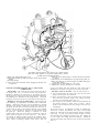
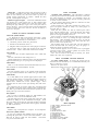
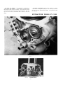
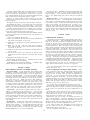
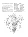
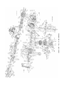
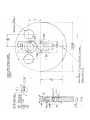
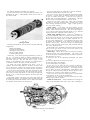
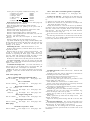
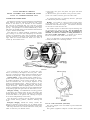
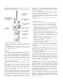
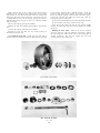
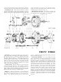
FIG. 1
The rotating oil pump plunger is here shown in situ, together with the
guide screw which registers in the plunger profiled groove, thereby
providing the reciprocating movement.
1 Dowel peg. locating timing gear cover.
5 Guide pin, for oil pump plunger. Inserted relieved tip downward
2 Timing side flywheel axle with integral gear for driving oil pump
as shown.
plunger.
6 Screwed body to accommodate the oil pump plunger guide pin.
3 Oil pump plunger.
7 Body, with guide pin in position engaged in profiled cam groove
4 Screw (one or three) with fibre washer, plugging oil passages cast
of oil pump plunger.
in crankcase.
8 Tapped hole, for pipe feeding oil to oil pump.
9 Tapped hole, for pipe returning oil to oil tank.
correct type timing side axle should he used, which can be
identified by the wider tooth gear for the latest type shaft.
Oil fails to return to the tank. This can only be due to:
(a) An air leak between the square cap at the rear end of the
plunger housing and the crankcase.
(b) There is obstruction in the oil passage (cast in the crankcase) from the crankcase sump to the plunger housing.
such as a piece of broken piston ring. etc.
(c) The housing in the crankcase where the large diameter of
the plunger operates is either worn or scored. This is
based on the assumption that the plunger revolves and is
undamaged.
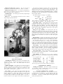
SINGLE CYLINDER ENGINE, 1957 to 1962 TYPES
LUBRICATION
The oil pump. The pump has only one moving part, this is
the plunger (see Fig. 1), which revolves and reciprocates.
Rotation is made by the worm gear on the timing side axle.
Reciprocation is created by the two piece guide pin. engaged in
the profiled groove machined in the pump plunger. Oil is fed
by gravity to the lower of the two connections on the crankcase
Damaged or worn teeth on pump plunger. Slight amount of
teeth marking, by engagement, is normal alter considerable
mileage. Where the teeth are worn or mutilated on the full
diameter of the plunger, examine the plunger for evidence that
the guide pin has been incorrectly located and has been in
contact with the body of the plunger adjacent to the profiled
groove. There will also be "witness" on the extreme end of
the guide pin. Where the damage is confined to a small
number of the teeth, this can be due to obstruction in the oil
feed to either the big end, or to the rocker box. The obstruction should be removed before replacing the damaged parts.
An incorrectly located timing side axle will have the same
effect. When overhauling engines made before 1961 the
In the case of (b) it is sometimes possible to dislodge the
obstruction without dismantling the engine (heavyweight
models) by removing the oil pump plunger also the crankcase
drain plug. A thin cycle spoke inserted through the drain
plug aperture may dislodge the obstruction. The remedy for
(c) is to replace the timing side half crankcase. Should oil
seep into the engine when stationary, this can also be associated
with (c).
11
Oil feed to rocker box cut off (all single cylinder engines).
If the rocker box feed pipe is unobstructed examine the end of
the pump guide pin for wear. A flat worn on this pin will cut
off the oil supply to the rocker gear.
key in the driving side shaft (see paragraph 'Engine noises').
A heavy oil discharge through the release valve tube (located
behind the rear portion of the front chain case) indicates an oil
accumulation in the crankcase, or abnormal positive crankcase
pressure caused by gas leakage past the piston rings.
LIGHTWEIGHT MODELS (only)
LUBRICATION
Oil fails to return from the sump. Take out the crankcase
filter and verify that the cap in the end of the filter tunnel is in
position and not sealing the oil return passage from the sump.
Examine also the right side of the plunger housing to ensure
that the steel sleeve 042044 is correctly located also the 'O'
ring is undamaged. Other details given for the heavyweight
models apply also to this type engine.
Heavy oil consumption (250 cc. Models). Where there is no
evidence of cylinder wear, or scored bore, use a Duaflex type
piston ring 043097 as fitted to the 1962 engine.
Note: The oil supply to the inlet valve guide should be
restricted as far as possible, in fact the regulating screw should
be opened to the smallest amount possible from the closed
position. There is considerable suction down the inlet valve
guide, coupled with the down draught inlet port.
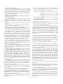
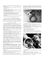
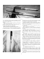
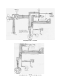
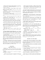
TWIN CYLINDER MODELS, 1957 to 1962
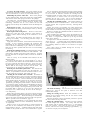
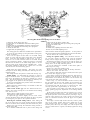
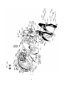
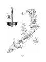
The design of the oil pumps for the Twin Cylinder Models,
first introduced in 1949, has remained unaltered by reason of
their reliability and longevity. Both pumps are of the gear
driven type, the feed pump circulates 26 gallons per hour at
6.500 r.p.m. The widest of the two pumps is for the return to
efficiently scavenge the crankcase. The two pumps can be
inadvertently reversed (see paragraph 'Over oiling'). The
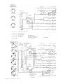
general arrangement of the pump assemblies are shown in
Fig. 2.
To keep the return pump 'wet* thus ensuring an
immediate oil return, when the engine is just started, a bleed
valve (see Nos. 1, 2 and 3 in Fig. 2) is mounted in the left-hand
side of the pump plate. Access to the ball and spring is made
by removing the grub screw (No. 3, Fig. 2).
Crankcase release valve (Heavyweight Models). On heavyweight models this is a flap valve, located on the drive side
crankcase adjacent to the drive side shaft, comprising a steel
diaphragm located in a serrated seat. If the valve becomes
inoperative causing oil leaks, the diaphragm is probably
trapped between the serrated seat and the crankcase. When
refitting this valve apply a grease to the serrated seat to retain
the diaphragm in position during assembly. A slight oil
discharge (condensed oil mist) is normal, a heavy oil discharge
indicates oil is accumulating in the crankcase (see paragraph
'Oil fails to return to tank'). The crankcase release valve on
the Lightweight engines is timed and ported in relation to the
piston position. The ported portion is rotated by a woodruff
Oil circulation. (Refer to general arrangement drawing,
Page 20). Oil is fed under pressure from the feed pump to the
filter tunnel under the influence of the pressure relief valve
plunger 026133. At the drive side end of the filter tunnel a
non-return valve 026139 which is spring loaded, is also part of
the filter assembly. When oil pressure is built up in the filter
tunnel the ball 011645 is moved off its seating, oil passes to the
two-way drilling for the main crankshaft bearings, with a
by-pass to the oil distributor compartment. From here oil is
distributed to the rocker gear by the oil distributor bush
022385, which is rotated by the exhaust camshaft. The oil
drilling in the crankcase is via the aperture for the bolt 014292.
which is sealed by the rubber backed washer 022580. Oil is
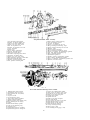
FIG. 2
Delivery Oil Pump (on the right). Return Oil Pump (on the left).
1 Ball, for non-return valve.
14 Screw (1 of 6) used to retain plates and bodies of oil pumps to the
2 Spring, for non-return valve.
carrying plate.
3 Plug, retaining non-return valve spring and ball.
15 Back plate of oil feed pump.
4 Bleed hole.
16 Dowel pin, locating pump plates and body.
5 Plate, carrying oil feed and return pumps.
17 Driven gear, for oil feed pump.
6 Paper washer for oil return pump.
18 Front plate of oil feed pump.
7 Back plate of oil return pump.
19 Screwdriver slot, to enable driving gear to be correctly positioned
8 Dowel pin, locating pump plates and body.
during assembly.
9 Body of oil return pump.
20 Driving gear, for oil feed pump.
10 Dog end of pump gear to engage in end of camshaft.
21 Body of oil feed pump.
11 Driving gear, for oil return pump.
22 Back plate of oil feed pump.
12 Driven gear, for oil return pump.
23 Paper washer for oil feed pump.
13 Front plate of oil return pump.
24 Bleed hole.
12
fed to a channel machined in both portions of the crankcase
(see paragraph 'Oil leaks from the cylinder base'). Two
metering plugs are used at this point to balance the oil feed to
the camshaft tunnels and the O.H.V. rocker gear. Drillings
in the face of the crankcase line up with holes machined in the
cylinder barrels also cylinder heads through which oil is fed
to the rocker spindles and bushes, which in turn falls by gravity
down the push rod tunnels into the camshaft chambers. The
main oil feed is taken to the centre web bearings, where it is
diverted to the connecting rod bearings. Overspill from the
camshaft tunnels causes oil to build up in the timing side
crankcase, lubricating the train of gears. A pre-determined
oil level hole in the crankcase wall keeps the oil level constant.
TWIN CYLINDER MODELS
found that the metering plugs are obstructed use a 1/32" drill
held in a pin vice to clear the drilling. The drill should be
manipulated with care to avoid breakage. If it is desired to
remove or replace these plugs, apply gentle heat to the cylinder
head, then push the plug through the drilling, when it will
come out of the hole in the rocker post. Insert the new plug,
small end inwards, a light tap with a centre punch inserted in
the larger hole will retain the plug in position.
OILING FAULTS
Oil builds up in crankcase (over oiling). This can be due to:
(a) The oil pumps have been reversed.
(b) There is an oil leak between the pump and the pump plate
(faulty gasket) or between the pump plate and the crankcase.
(c) Obstruction in the form of a broken portion of a piston
ring, sucked into the oil passage cast in the crankcase to the
return pump drilling, or the pumps are loose on the pump
plate.
Oil failure to big end journals. The big end shells used on
the Two Cylinder Models are materially and dimensionally
identical to those used on high-powered racing motor car
engines. With smooth journals and a continuous supply of
clean oil, these bearings will be trouble free for many thousands
of miles. If the oil supply is cut off, even temporarily, the
bearings will run and usually the drive side is the first to be
affected. This is because the overspill from the timing gear
falls on to the timing side crankshaft, which keeps the bearing
'alive' for a slightly longer period. When the bearing 'runs'
the clearance between the con rod and the crankshaft increases
considerably. The hammering effect produced will tend to
loosen the con rod nuts, which gives rise to the opinion that
loose nuts are responsible for the trouble. With further use,
and the engine in this condition, can result in a broken con
rod, with additional damage. It follows that should an
unusual noise develop, the cause should be investigated without delay. It is imperative that the reason for the oil shortage
is traced and rectified before the crankshaft is assembled also
reinstalled into the crankcase.
(d) The gears are damaged, on the return pump, by the introduction of foreign matter (portion of piston ring).
In the case of (b) if the pump plate is bruised or deformed at
the point where the oil pick up takes place, the oil return will
be spasmodic. When there is evidence of air bubbles emerging from the spout in the oil tank, this indicates an air leak.
If difficulty in dislodging the obstruction occurs, a good tip is
to feed a line of ¼" diameter ball bearings down the passage
cast in the crankcase and when nearly full apply pressure on the
last ball, which should push out the obstruction. If a machine
is left stationary for a lengthy period, oil can accumulate in the
crankcase, due to a slight seepage past the oil feed pump, which
is inevitable. Should this happen after standing for a short
period, check the feed pump for loose fixing screws on the
pump plate (No. 18, Fig. 2).
Oil discharge from crankcase into chaincase. This is usually
due to the crankcase release valve being deranged. This
valve also retains the engine sprocket to the crankshaft.
Should the diaphragm be buckled or trapped oil will escape
from the crankcase into the front chaincase. This oil discharge will also occur if oil builds up in the crankcase as
previously described. Abnormal positive crankcase pressure
caused by gas leakage past the piston rings can have a similar
effect. A distance piece is used between the engine sprocket
and the main crankcase bearing. The outside diameter of
this distance piece is a close fit in the crankcase, being designed
to prevent oil leakage. If the aperture is damaged or deformed, an efficient seal cannot be made, which would result
in a build up of oil in the front chaincase.
Possible cause of oil failure. If the fault develops after an
oil change or when the engine has been refitted to the frame,
the oil pipes may be reversed at the oil tank end.
Crankcase filter. Early I960 engines were issued with a
close mesh gauze metal filter (see table of oiling modifications).
If this type of filter has collapsed, this indicates that oil cannot
pass through the filter. Lack of cleaning and the use of
additives, which lend to varnish the outside diameter of the
filter, prevents oil penetrating. This type of filter should be
discarded and replaced with the modified, felt type.
Non-return valve. Make sure the ball can be lifted off its
seat, the spring may be corroded.
Pressure relief valve. This is a vital part of the oiling system.
On earlier type engines (sec table of oiling modifications) this
valve was located in the liming side crankcase, just below the
dyno fixing stud. The valve consists of a spring loaded
plunger, the spring will be exposed when the timing cover is
removed. If the spring is buckled, or there is foreign matter
in the plunger orifice, the plunger will be held off its seat,
thus cutting off the oil supply to the engine.
Oil shortage to rocker gear. If the oil supply to the rocker
gear is cut off, first check the metering plugs 018890 in the
cylinder heads by removing both heads and take out, in turn,
the rocker spindles which are held in position by the clamp
bolt (No. 10, see Fig. 4) and note the location of the plain
also spring washer. The oil feed hole drilled in the rocker
post will now be exposed. Force petrol through this aperture
which should emerge through the metering plugs, if they are
unobstructed. Check also the oil hole in the cylinder, which
may be masked by the base washer or head gasket. If it is
Twin Cylinder Models, made in 1960 and onwards, the
pressure relief valve was transferred to the base of the filter
13
compartment (see 'general arrangement' Drawing Fig. 6),
the plunger 026133 is retained by a spring, washer and circlip.
The possibility of this valve becoming deranged is extremely
remote. A case has been known where the valve washer
026134 has been trapped in the square bottom recess machined
in the timing cover. Originally this recess was ½" diameter,
which in the interest of safety should be enlarged to 17/32".
With the engine in a dismantled state, test the plunger for free
movement by pressure on the plunger with a suitable object.
Engine noises (Twin Cylinder Models). No engine will
remain mechanically quiet throughout the whole period of its
life, so after considerable mileage some engine noise is
inevitable. Under such conditions the possible engine noises
are detailed together with the symptoms to assist in quick
detection. Firstly, disregard the so-called experts' diagnosis
of 'worn small end bearing' (wrist pin), as this does not
happen on the twin engine.
Oil distributor bush (022385). As previously described, this
rotating bush delivers oil to the rocker gear and needs no
attention. It is of paramount importance to use a copper
washer of the correct thickness, between the cap 014247 and
the crankcase, the washer should be 1/16" thick. The use of a
thin washer will lock the bush solid with serious damage to
the crankcase.
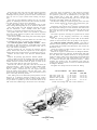
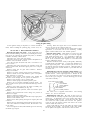
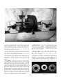
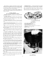
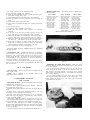
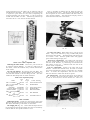
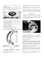
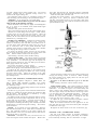
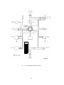
Checking the oil pressure. After engine overhaul, or when
an oil feed shortage has taken place, when the engine is
refilled to the frame, the oil pressure should be checked. An
oil pressure gauge reading from zero to at least 150 lbs. per
square inch is required. It must be mentioned that when a
pressure relief valve is not incorporated in the oiling system
(see table of oiling modifications) the engine must idle for
several minutes until the oil has become warm and the viscosity lowered. Spinning the engine in a cold condition will
generate a pressure of about 300 lbs., which can burst the
gauge.
The application of the gauge can be seen in Fig. 3.
The shank of the gauge should be ¼" B.S.P. (.518) x 19 T.P.I.
Use a filter compartment cap of an early type 016179 assembled
with ball and spring to accommodate the gauge, for test
purposes. When an oil pressure relief valve is fitted, the
recorded pressure when cold is between 100 to 110 lbs. per
square inch falling to 25 to 30 lbs. when hot. Without a
relief valve the pressure is about 140 lbs. after warm up and
25 to 30 lbs. hot. In the event of damage to the thread in the
crankcase for the cap 016179 use a tap 11/8"x20 T.P.I. to clear
the threads. This tap can also be used for the oil distributor
cap orifice.
Oil leaks (Twin Cylinder Models). If the engine is carefully
assembled, oil leaks are extremely rare, providing the gaskets
are sound and not deformed during the process of assembly.
FIG. 3
Oil leaks from cylinder head joint. If the oil leak is persistent
and does not respond to the use of new gaskets, the cylinder
head face may be distorted. To remedy, the head face should
be 'rubbed down' on a face plate, alternatively, use a sheet of
reasonably coarse emery cloth placed on a stout sheet of glass
until the head face is perfectly flat. Use also heat treated
cylinder head holding down nuts (Part No. 028082).
Overhead rocker noise. This can develop if the rocker
clearance is excessive and is easy to locate. An oil shortage to
the rocker gear will produce a similar noise, with the possibility of wear on the valve ends, also rockers. If the wear
on the rocker end (which makes contact with the valve) is
to any noticeable extent the use of a feeler gauge will give a
false reading. If the wear is slight, the rocker gear can be
hand stoned to remove the ridge formed by wear.
Oil leaks from cylinder base. An oil leak from this part of
the engine may develop after the cylinders have been removed.
When the leakage persists, and when the base joint is remade,
without improvement, it is quite likely that the leak is from
the crankcase joint and not from the cylinder base. As
explained previously in paragraph 'oil circulation', oil is fed
under pressure to a channel in the crankcase midway between
the two cylinders. During the process of removing and refitting the cylinders, the crankcase joint has broken down,
particularly if the bolts passing through the crankcase have
been released, or if the cylinders have been 'racked" sideways to
remove them. To prove if the leak does come from the crankcase joint, take off the right side cylinder head and barrel.
Use a WESCO pressure oil gun, with the spout placed in one
of the two oil holes drilled in the crankcase spigot aperture,
seal off the other hole with one of the fingers of the free hand.
Work the gun to build up pressure, if the crankcase joint is
leaking, oil will emerge between the two halves of the crankcase midway between the two cylinders.
Cam follower wear. This noise is usually audible when
running between 30 to 40 m.p.h. and is not affected by load
on the engine. As a temporary measure close up the rocker
clearance to .002 on all valves. If the noise is still there, the
followers are worn. If after examination, the exhaust cam
followers only are worn, this would suggest overload by the
valves being tight, or prone to seize in the valve guides. After
reassembly the valve motion should be checked to verify that
the valve springs do not become coil bound when the valve is at
full lift. This can happen when pattern valve springs are used,
or the lower valve spring seat has been fitted upside down.
The wide face of the spring seat should abut against the valve
guide boss on the cylinder head.
Big end noise. Can be detected when engine is running at
a small throttle without load, or when the machine rotates the
engine on down gradient. This noise usually disappears
when the engine is pulling.
14
Technical aspect of the Twin Cylinder Models. The twin
cylinder engine for Touring Models was first produced in
1949. Since this time the design has undergone many changes,
far too numerous to describe in this manual.
In the main the technical details given are to cover engines
made from 1957 onwards, although a description of lubrication modifications are mentioned in preceding chapter for
earlier models.
Engine design. Originally the cubic capacity of the 500 cc.
Twin was 498 c c , bore size 66 mm., stroke 72.8 mm. Then the
600 cc. engine was introduced, capacity 592 c c , bore 72 mm.,
the stroke being the same as the 500 cc. version. From this
it is apparent that the technical aspect of both engines are
identical with the exception of carburetter settings and engine
sprocket size, which are given in Technical Data.
Raising the compression ratio. This is accomplished by
exchanging the pistons. A table of pistons available for twin
cylinder engines indicates the part number, also ratio for
identification. The part number for the bare piston is
quoted, which is stamped on the piston crown.
1957-59
500 cc.
Standard ratio
H.C.
600 cc.
Standard ratio
H.C.
650 cc.
Standard ratio
H.C.
The 650 cc. engine was first introduced in 1959, which has a
cubic capacity of 646 c c , bore size 72 mm., stroke 79.35 mm.
The standard engine uses a compression ratio of 7.5 to 1.
The CS and CSR models have a ratio of 8.5 to 1, which
necessitates a slightly retarded ignition timing (see paragraph
'setting ignition') and KLG FE220 sparking plugs.
1960-62
022415(7/1 C.R.) 026323 (8/1 C.R.)
022598(8/1 C.R.)
022226(7.4/1 C.R.)
023503(8/1 C.R.)
025042(7.5/1 C.R.)
025045(8.5/1 C.R.)
026324(7.5/1)
026325(8.5/1)
Valve springs. Whilst the valve springs used on various
Twin Cylinder Models are similar in appearance, they differ
in free length, also on poundage when assembled.
It is important to use the correct type of springs to avoid
overloading the cam gear, apart from the risk of the springs
being coil bound, when the valve is at full lift.
Camshafts. An improved type of camshaft was introduced
in 1959 for the CSR Models which can be used in all twin
cylinder engines. Earlier types are no longer available.
Replacements now issued will be of the improved type.
TABLE OF VALVE SPRINGS
Fitting new camshafts. It is essential when new camshafts
are fitted particularly to early type engines, that the valve
motion is checked when the engine is assembled as far as
adjusting the rocker clearance. Deal with each valve in turn
by turning the engine until the valve is at full lift (fully open)
when it should be possible to compress the valve spring
further by applying pressure on the rocker to a minimum of
.040" (1 mm.). This is to ensure the valve springs are not coil
bound, or closing up solid at full lift. This can also happen if
the valve spring seals have been reversed (the wide face
should go against the cylinder head) or pattern type valve
springs are used. An incorrectly located valve guide will also
limit valve movement thus causing cam gear wear.
All 500 cc. and 600 cc. engines (1949-1959).
Part No.
011770 Inner spring
011769 Outer
Free
Number
length.
of coils.
Wire gauge.
19
1 /32"
7
12 S.W.G. (.104)
1¾"
6
9 S.W.G. (.144)
500 cc. and 650 cc. engines (1960—onwards).
018347 Inner spring
2.030"
8¾
018348 Outer
2.523"
8
.116"
.140"
Note: This type of valve spring must NOT be used on
engines made before I960. These springs are rated, the end
marked with yellow paint is assembled against the cylinder
head. The inner spring is an interference fit with the outer
spring to prevent valve spring surge.
Cam followers. If premature wear occurs with this part of
the engine, the cause can be due to overload (see paragraph
'Valve springs'). The use of unsuitable lubricating oil will
affect cam gear wear. If the wear is confined to the exhaust
cam followers only, the exhaust valves may be tight in the
valve guides when the engine reaches its normal running
temperature (see Technical Data for dimensions). Continual
short distance running can have some bearing on this trouble.
The use of delcrome cam followers used on late 1962 engines
will offset premature wear.
TABLE OF SPRINGS (Twin Lubrication System)
1957 Models (only)
Spring for crankcase release valve 018282 9/16"+ 3/8" 10 coil
26 gauge.
Cylinder heads. Cylinder heads on the 500 cc. and 600 cc
engines were identical prior to 1957 when a slightly larger
valve head diameter was introduced. The inlet port was also
enlarged to 1 1/16" for the 600 cc. engine. A new design of
cylinder head is used on all twin engines made for 1960
onwards. The head sphere is more shallow, with an alteration
to the shape of the piston crown. The new parts do not
interchange with earlier types.
To convert, new cylinders also cylinder heads and pistons
together with new type head gaskets, are required.
Connecting rods. All connecting rods used on the twin
engine since its conception are materially and dimensionally
identical with one exception, namely, the detachable cap on the
connecting rod which is chamfered to clear the crankcase for
the 650 cc engine. If an early type rod is used as a replacement, the cap must be filed to give the required clearance
There is also a chamfer on one side of the connecting rod just
above the big end 'eye'. The rod should be assembled with
the chamfer pointing away from the centre of the crankshaft to
clear the crankcase.
1957-1959
Spring for filter non-return valve 014241 1½"+5/16" 15 coil
17 gauge.
Spring for pump bleed valve 000701 19/32"+¼" 10 coil
26 gauge.
1960-1962
Spring for pressure relief valve 026132 .984"+.423" 9 coil
18.1 gauge.
Ball for pump bleed valve ¼" diameter.
Ball for non-return valve 3/8" diameter.
Timing gear noise. This is due to backlash between the
train of gear wheels in the timing cover, and is most pronounced when the engine is idling. Wear on the bush or
shaft for the intermediate pinion can be responsible. A new
pinion with closer mesh is also beneficial.
15
Piston slap. A little piston noise when the engine is cold is
not unusual, particularly when high compression pistons are
fitted. In the ordinary way this noise clears up when the
normal running temperature is reached. Should the noise
prevail, a seized piston is suspect.
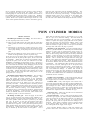
TWIN CYLINDER
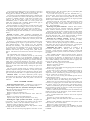
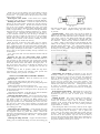
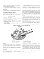
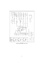
Overhead rocker adjustment. This adjustment is effected
by turning the eccentric rocker spindle to increase, or decrease,
the rocker clearance as desired. As quietening curves are
used on the camshafts the engine must be correctly positioned
to obtain correct clearance.
All twin engines made before 1960 use a clearance of .006"
and .008" after 1960, engine cold.
Tools required are:—Allen Key 018055 for rocker cover;
open end spanner 015264 for clamp nut; feeler gauges or
strip foil .006" or .008".
Deal with one cylinder at a time by removing the rocker
cover, also the sparking plug. Close the throttle, turn engine
slowly until the inlet rocker goes down and returns. The
piston is now approximately on T.D.C.
Insert a spoke, or stiff wire through plug hole to ensure the
piston is exactly on T.D.C. by rocking the engine backwards
and forwards. Slack off slightly the nut (8) (Fig. 4), turn the
rocker spindle (12) to raise the rocker away from the valve
(there is a slot in the spindle end).
Put the feeler gauge on the valve stem, turn the spindle in
reverse direction until the rocker just 'nips' the gauge, retighten the clamp nut without undue force.
If the clearance appears to be in excess refer to paragraph
'overhead rocker noises'. Inspect gaskets for rocker covers
and renew if they are damaged.
Note: Do not unscrew the clamp nut unduly, the thrust
washer will come out of position.
Rattle in top part of engine. A noise that is difficult to locate
can develop as a result of either one, or both, exhaust pipes
becoming loose in the exhaust ports, when the engine is hot.
Rocking the pipe sideways to get it out of the port tends to
close in the pipe. Drive a steel or hard wood tool shaped like
a carrot into the pipe end to 'bell out' the end to make it a
close fit in the port.
TABLE OF OILING MODIFICATIONS
1956 Twin Cylinder Models
1. A balanced oil feed to cam tunnels and O.H.V. rocker
gear introduced, by using two metering jets in the channel
machined in the crankcase (sec 'Lubrication').
2. Crankcase pressure relief valve discarded.
3. Oil hole in oil distributor bush 1/32".
4. Magnetic filter incorporated in drain plug for crankcase.
5. Oil feed to O.H.V. rocker gear diverted to the top front
crankcase bolt. Bolt is sealed with rubber-faced washer.
1957 Models
Non-return valve for filter compartment now a sealed unit
023331.
Oil hole in distributor bush enlarged to 3/64".
Tufnol diaphragm for crankcase release valve discarded and
replaced with steel type, use spring also for diaphragm.
TWIN CYLINDER ENGINE SERVICE
To remove cylinder heads. To ensure the various parts of
each head are not intermixed, it is recommended that only one
head is removed at a time.
Remove the petrol tank.
Remove the rocker box covers, as already described.
1958 Models
Hole 3/64" in oil distributor bush discarded. Bush now uses a
flat machined on outside diameter of bush.
1959 Models
The four metering plugs in the cylinder heads discarded.
New type crankcase release valve sealed unit type introduced.
1960 Models
A 3/32" hole drilled in the cylinder spigot aperture (drive side
only) the intention being to increase the oil supply to the drive
side cylinder and piston. Engines with number X1994 to
X2619 had a similar hole in the cylinder spigot. These
cylinders must be used on the right (timing side) side of the
engine.
An improved type of pressure relief valve introduced and
now located in the base of the crankcase filter compartment.
The fabric type crankcase filter discarded and replaced by fine
metal gauze type with valve attached.
1961 Models
The 3/32" hole in crankcase spigot (see 1960 Models) now
transferred to the end of inlet camshaft tunnel.
Oil spills from the hole on the inside wall of the drive side
crankcase so falling on to the crankshaft bob weight. From
here oil is flung up and into the near side cylinder to augment
oil supply. The four cylinder head metering plugs discarded
in 1959 re-introduced.
FIG 4
Rocker adjustment.
1 Plain washer—mentioned above.
2 Spring washer.
3 Plain washer.
4 Rocker.
5 Cylinder head.
6 Rocker Clearance .008".
7 Valve spring cap.
8 Clamping bolt nut.
9 Clamping bolt washer.
10 Clamping bolt.
11 Cutaway on rocker spindle.
12 Eccentric rocker spindle.
1962 Models
Duaflex rings incorporated to improve oil consumption.
1962 Twin Cylinder Models
A new type crankcase filter 028496 using a felt fabric surrounding the gauze filter is used on the above Models. This
filter can be used in 1960 and 1961 Models. Clean filter
every three thousand miles.
16
Remove the sparking plugs.
Remove the exhaust pipes and silencers (no need to separate
pipes and silencers) by taking away nuts and washers holding
pipes to stays and silencers to rear frame, pulling silencer end
of each assembly outwards far enough to allow fixing studs to
disengage and then pulling each assembly forwards till disengaged from the cylinder head.
Remove air filter (if fitted).
Remove carburetter by taking away the two fixing bolts and
withdrawing to the rear.
Lay carburetter aside.
Remove inlet manifold by taking away the four fixing nuts
and washers and withdrawing to the rear. Take care not to
damage the gaskets between manifold and heads or rubber
ring insert.
Remove cylinder head steady plate (secured by three bolts
and nuts).
Remove heads by using box spanner 015213 to remove the
four nuts that retain each head.
After removal invert each head to dislodge the spacers
under the nuts and lay aside to await re-assembly.
The cylinder head gaskets will generally adhere to the tops
of the barrels, but care must be taken not to damage them.
Oversize or Undersize parts: The following are the only
'oversize' variations provided for the vertical twin machines:
Big-end and crankshaft centre main bearings:
Undersize: .010 below normal (journals to be re-ground to
suit).
.020 below normal (journals to be re-ground
to suit).
.030 below normal (journals to be re-ground
to suit).
Cylinder re-bore: .020" and .040" oversize. (See 'Technical
Data' for normal size.)
Pistons and rings: .020" and .040" oversize. (See 'Technical
Data' for normal size.)
Fitting pistons and cylinder barrels. Pistons to be free of
carbon on their crowns and all piston ring grooves to be clean.
Piston rings to be clean and on pistons.
Fit a piston to its connecting rod by: Smear gudgeon pin
with clean engine oil. Place piston over connecting rod, introduce
gudgeon pin to piston and pass through connecting rod, press
right home against the circlip still in situ. Then again using
pliers 011188, contract the other circlip, introduce same into
its groove in the piston, using a rotary movement. Make
quite certain that the circlip lies snugly in its groove because
failure to do so will inevitably lead to serious damage. (See
Note above.)
To remove the valves. First remove rockers from cylinder
head (see Fig. 4).
The importance of correctly locating the
valve spring seats is stressed, the wide face of the seat abuts
against the cylinder head. Reversal will make the springs
coil bound and cause damage to the valve gear. Proceed by
removing the rockers (see Fig. 4 for assembly sequence).
If a valve spring compressor is not available, use a wood block
2" in cube to support the valve with the head on a bench.
Compress the springs to extract the split collets, which are a
taper fit. A sharp tap on the spring collar will release them.
If the valve springs are retained, identify their location for
refitting. Check the four metering plugs in cylinder heads for
obstruction, before refitting rockers.
To remove valve guides. Both guides are a force fit and
located by circlips, the cylinder head must be uniformly
heated, the guide can then be pressed out of the port sufficiently
to remove the circlip.
Reheat the head, press down the guide from outside the port.
Removing cylinder barrels and pistons. Unless it is desired
to inspect the pistons and rings during decarbonisation, they
are, as already advised, best left undisturbed. Having removed
the cylinder heads, withdraw the cylinder barrels by: Lift
away the four push rods, identify them for refitting and lay
aside. Dealing with one barrel at a time, exert upward
pressure on a barrel, slightly rocking to and fro while doing
so, and steady the piston with one hand as it emerges from the
barrel. Cover the crankcase throat with clean rag to prevent
entry of foreign matter.
Before fitting the cylinders, make sure they arc clean and
examine the base washers and renew same if not perfect.
To fit new cylinder base washer, first clean off the old
washer and all traces of jointing compound. Then smear one
side of the new washer with jointing compound and, when that
is nearly dry ('tacky') apply to the cylinder.
Place rings on piston, scraper first, then the two compression
rings.
On all models, the top compression ring is chromium plated.
These chrome plated rings have a slightly tapered exterior and
when new are clearly marked with the word 'TOP' on one side
to indicate assembly position.
After use, this word tends to become indiscernible, but
over a large mileage the assembly position can be determined
by brightness of the edge contacting cylinder wall. This bright
edge is the lower one. When as the result of wear, contact
with the cylinder wall appears uniform over the whole width
of the ring, it is immaterial which way round it is refitted.
The 650 cc. two-piece ring, if used, is marked 'TOP'. Space
the piston rings so that the gaps are 120° to each other,
smear piston and rings and bore of barrel with clean engine oil
and supporting the piston with one hand, gently pass over the
barrel, compressing each piston ring with the fingers, as it
enters the barrel. Press the cylinder barrel right down into the
throat of the crankcase.
To remove piston. Using 011188 circlip pliers, contract one
of the gudgeon pin circlips and with a rotary motion, gently
withdraw the circlip from its housing. The gudgeon pin
may then be pushed out of the piston, which action frees the
piston from the connecting rod.
(Being a parallel, floating fit in the piston and connecting
rod, small end it is immaterial from which side the gudgeon
pin is withdrawn.)
Note: It may be necessary to apply a little heat to the piston
to permit free gudgeon pin removal and replacement.
Rings may be removed from a piston by peeling off or by
introducing behind them three thin and narrow metal strips,
equally spaced round the piston, and then sliding them off,
taking care not to scratch the piston.
Carefully examine the contact edge of each piston ring and
replace any which do not show a bright surface over the whole
circumference.
Fit the second piston, gudgeon pin, rings and barrel in a
like manner.
Revolve the engine till the pistons are at the top of their
strokes and' then, with a clean rag, wipe off all surplus oil.
All is now ready to re-fit the cylinder heads.
To re-fit the cylinder heads. Note: If the nuts retaining the
cylinder heads are finally tightened before the manifold is
fitted, a bias can develop between the manifold to cylinder
head joint, causing a bad air leak.
Clean the valve stems and the bores of the valve guides with
rag moistened with petrol, make sure all other parts are clean,
then smear each valve stem with clean engine oil and proceed
to re-fit the valve stems by reversing the procedure taken to
dismantle them.
17
Insert the four valve push rods into their original positions
and after making sure that the cylinder head gaskets are
undamaged and in position, proceed to fit the two heads and
leave the two sets of four cylinder head retaining nuts finger
tight.
Now refit the inlet manifold, making sure the two paper
gaskets are undamaged and leave the four retaining nuts only
just tight enough to ensure correct alignment.
Next, fully tighten down the four retaining nuts on each
head, treating each diagonally bit by bit, till all are fully down.
Then fully tighten the inlet manifold retaining nuts and
refit the carburetter. Next, carefully check each rocker
clearance, as previously described and reset if necessary.
The gasket under each rocker cover should be inspected
and if not sound, should be replaced, after which the rocker
covers can be refitted.
Next refit the cylinder head steady plate and securely tighten
the three fixing bolls.
Note: Before refitting carburetter make sure the rubber ring
in manifold joint face is in position and undamaged.
To re-time the ignition—Twins (Magneto Models). Before
proceeding to time the ignition it is advisable first to check
the contact breaker point gap, which should be from .012" to
.015", and correct if necessary.
Having loosened the nut securing the magneto driving
pinion, release same from the tapered end of the magneto
shaft by means of a special extractor, as described on page 19.
Remove the inlet rocker cover from the off-side cylinder
head.
Remove the sparking plug from the off-side cylinder.
Insert a small rod into the sparking plug hole, feeling the
piston with the end of this rod, carefully turn the engine in its
normal direction of rotation until the piston is exactly at the
top of the stroke after the inlet valve has closed.
Hold the rod vertical in plug hole, mark the rod where the
plug boss registers. Take out the rod, make another mark
higher up 3/8" for the 500 cc. and 600 cc. twins or 11/32" for the
650 cc. models. Re-insert the rod, turn engine backwards
until the higher mark registers with the plug boss. This
applies also to the standard twins. Place the ignition control
lever in the fully advanced position.
Next, taking care not to disturb the piston position, turn the
magneto in a clockwise direction (looking at the contact
breaker end of the magneto) until the contact breaker points
are just about to separate by reason of the fibre block on the
bell crank lever commencing to mount the lower cam hump.
The exact point of separation is best found by inserting
between the contact points a strip of thin tissue paper when
the separation point can be determined by the paper just
being released with a light pull. Having obtained this
position, press the magneto driving gear on to its taper with
the fingers and lightly tighten the securing nut.
Re-check the timing by re-positioning the piston and when
correct, securely tighten the nut fixing the ignition drive gear.
3
/8"=39° 11/32"=35°
Thoroughly clean off all traces of jointing compound from
face edges of the timing cover and crankcase, then smear both
faces with new jointing compound, which leave till tacky and
then re-fit the cover to the crankcase. ('Wellseal' recommended.)
The whole operation of liming the ignition will be found
quite simple if the foregoing instructions are carefully
followed.
Note: The sparking plug high tension cable for the off-side
cylinder is that connected to the rear pickup on the magneto.
To re-time the ignition (Alternator Twins). First refer to
Electrical Section, paragraph 'Coil Ignition Standard Twins'.
to understand the principle of the distributor, then remove the
distributor cover.
Check the contact gap which should be between .014" and
.016", release clamp bolt, etc.
Position the engine as described for the Magneto Models.
If the distributor has been removed, the distributor shaft with
the rotor fitted when replaced should be in the approximate
position as shown, which is the firing position for the left-hand
cylinder. From the near side of the machine turn the rotor
in a clockwise direction (fully advanced position). Whilst
retaining this position turn the distributor body until the
contact points are just about to break (see method described
for Magneto Models).
Re-tighten the clamp bolt and re-check the timing.
VALVE TIMING.
ALL TWIN MODELS
1957-1958
1959-1962
24° b.t.d.c,
37° b.t.d.c.
Inlet valve opens
Inlet valve closes
65- a.b.d.c.
77° a.b.d.c.
Exhaust valve opens
63' b.b.d.c.
73° b.b.d.c,
Exhaust valve closes
25° a.t.d.c.
43° a.t.d.c.
(Check valve timing with .012" rocker clearance.)
FIG. 5
Coil Ignition timing.
18
Upon removing the timing gear cover (secured by 10 screws)
also the pump plate assembly, it will be observed the valve
timing gears are marked to facilitate correct assembly.
One tooth gap of the mainshaft small pinion is marked with
one centre punch dot and a tooth of the idler pinion into which
it meshes, is similarly marked. With these two marks coinciding it will be seen that a tooth on each side of the
intermediate pinion is marked with two centre punch dots
which also coincide with a similarly marked tooth gap on
each of the camshaft driving gear wheels.
During assembly it is only necessary to mesh the gears with
these various marks coinciding to ensure correct valve timing.
The dynamo and magneto drive pinions are not marked.
The dynamo does not need 'timing' and if, for any reason,
the magneto timing has been disturbed, it is reset as described
earlier.
springs and cups, then the pressure plate or pull off the plate
with the springs and cups in it.
Use a stout box key for the gear box mainshaft nut 13/16"
across the flats, press again on the brake pedal and remove
the nut. Take out the chain connecting link the clutch, rotor
(if fitted) and engine sprocket, watch for the engine sprocket
distance piece behind the sprocket.
Instead of using the rear brake whilst releasing the clutch
and engine sprocket nut, the 'easy to make tool' shown in
Fig. 51 will provide a more positive means to release these
nuts. See Lightweight.
Removing rear portion chaincase. Remove three countersunk screws at front end. Remove central nut, if alternator is
fitted. Remove chaincase portion. Drain the oil tank.
Disconnect both oil pipes at crankcase end first, then detach
the pipes from the oil lank. A piece of wood or a stout screwdriver placed under the tank can be used as a lever to separate
the pipes from the tank. If an engine overhaul is contemplated take off the oil tank for a thorough cleaning.
Removing the crankcase assembly. Remove distributor
cover and l.t. wire or magneto control wire and h.t. cables,
whichever fitted. Remove the dynamo if fitted.
Remove all bolts passing through the crankcase and frame
and release only the two gear box fixing nuts. Grasping the
cylinder studs, lift the crankcase clear of the frame.
Dismantling the engine. Cleanliness in working is of
paramount importance in dealing with an engine of
this kind. Clean down the crankcase and get rid of all road
grit from the bottom portion, before the assembly is placed on
the bench.
Have available magneto pinion extractor 015273, extractor
for cam wheels 015374.
If the work involved is confined to
the cam gear, the magneto, or distributor can be left in situ.
The pinion for ignition can be marked with a red paint line,
with a similar marking on the inlet cam wheel in register, thus
leaving the ignition liming undisturbed.
Remove the timing gear cover screws 011820.
Remove nut fixing dynamo.
Remove timing cover.
Remove three nuts 014903 securing pump plate to crankcase
and take away pump plate.
At this stage a tool to hold the crankshaft from turning is
desirable. A tool for this purpose is described in table of
'improvised tools'. Alternatively, put back the engine sprocket
and use a chain bar as shown in Fig. 52.
Note: The two nuts securing the camshaft pinions have a
left-hand thread 011653.
If the magneto has to come off, use the extractor which is
also made to remove the small timing pinion 016209.
Remove the two cam wheel nuts 011653, fit the bridge type
extractor by engaging the two outside bolts into the holes in
the pinion, screw in the central bolt to pull off the pinions.
Remove intermediate gear pinion 021506, the small timing
pinion 016209 can remain in position as it will pass through the
crankcase, as will the dyno pinion.
Remove crankcase filter unit 026139, the oil distributor cap
014247 and take out the distributor, three 014292 crankcase
bolts and bottom crankcase stud.
Note: A rubber-backed seal washer is used on the top front
bolt 014292.
Set both con rods at bottom dead centre.
Remove timing side half crankcase from drive side crankcase.
Remove both camshafts, cam followers and spacers (note
their location), also tunnels 016472.
Remove six centre web stud nuts 011843.
Remove crankshaft with centre web assembled, the inner
members of the two main bearings will come away with the
crankshaft.
Removal of gears. When completely dismantling the
engine there is no necessity to remove the small timing pinion
from the crankshaft before splitting the crankcase because the
complete crankshaft can be taken away with the pinion still
in position.
If, however, it is desired to remove the pinion without completely dismantling the engine a special extractor is required
(part number 015273). This consists of a nut, threaded
externally and internally. The external threads enable it to
be screwed into the threaded centre of the pinion and the
internal threads accommodate a specially designed and
hardened bolt which, upon screwing down, pulls off the
pinion. This same tool is used for the removal of the magneto
gear.
The intermediate gear needs no extractor.
The gears on the two camshafts (secured by nuts having
left-hand threads) have to be mechanically withdrawn and
each has two holes drilled and threaded to accommodate the
two bolts of a bridge type extractor (part number 015374),
which has a central bolt threaded in the bridge. The two
outside bolts are screwed into the holes in the gears whereupon
application of the centre bolt being screwed into the bridge
bears on the end of the shaft thereby causing the gear to be
withdrawn.
The gear on the dynamo needs no extractor because the
dynamo, complete with gear assembled, is easily and quickly
removed from the engine and the subsequent removal of the
gear from the dynamo shaft is a simple workshop operation.
Alternator Twins. To remove distributor pinion, spring
outwards the circlip, take out the parallel pin passing through
the pinion and distributor shaft—the pinion can then be
removed.
TWIN CYLINDER MODELS
Removing engine from frame. Commence by removing the
cylinder heads, cylinders and pistons as detailed earlier.
Removing the chain case (Alternator and Magneto Models).
Take out the drain plug and catch oil in a tray.
Remove left side footrest.
Remove brake rod adjusting nut.
Remove inspection cap and alternator wires from connectors.
Remove 14 screws and central fixing nut.
Depress brake pedal and pull chaincase cover away.
Removing the engine sprocket and clutch. Straighten the
tab washer, use a close fitting ring spanner for the engine
sprocket nut, which is also the crankcase release valve.
Refit the brake rod adjuster, engage top gear.
Press on the brake pedal and give the ring spanner a series
of sharp blows to release the nut.
Remove the three clutch spring adjusters and take out the
19
20
FIG.
6
To remove the distributor (fixing as for magneto). Spring
outwards the circlip, the parallel pin can then be pushed out
through the pinion and distributor shaft. The pinion can then
be removed.
To remove the magneto. The magneto is located by a
spigot on the magneto body. A paper gasket is used between
the magneto body and the crankcase. With magneto pinion
removed, remove the three nuts fixing the magneto. The two
top nuts are on studs, a detachable bolt is used for the lower
fixing.
EXTRACTOR TOOLS IN USE
FIG.
FIG. 8
7
Camshaft Removal
21
If a con rod bearing has been deprived of oil, and the bearing
has 'run', without prompt attention the hammering effect, due
to the increase in clearance between the bearing and the
crankshaft journal can cause ovality in the connecting rod eye.
Usually there is a witness in the con rod eye and in this
condition the con rod is scrap. On no account should the
faces between the detachable cap and the con rod be filed.
To remove the main bearings. The inner member for the
main bearing will remain on the crankshaft when it is extracted.
Use two screwdrivers, or levers, to prise off the bearing.
Dismantling the pressure relief valve. Press on the plunger
via the crankcase filter tunnel and extract the circlip 040049.
Take off the washer and spring and remove the plunger.
The centre web. The detachable cap is marked with a letter
'O', the centre web has a similar mark for location after
machining. Hold the web in a vice, remove the two selflocking nuts and lift up the crankshaft which will dislodge the
cap.
Removing the con rods. The caps on both connecting rods
are marked after machining, with an oblique stroke (/), running
across the cap and con rod.
Removing the main bearing sleeves. These are a close interference fit in each side of the crankcase, some patience is
needed to remove them if damage to the crankcase is to be
avoided.
First remove the metal extruded during the process of
'peening' on assembly. Use the sharp point of a scraper, or
similar tool, to do this.
Apply heat to the crankcase, concentrated round the bearing
housing. In this condition, dropping the crankcase face
downwards on to a clean wooden bench, will start the movement of the sleeve sufficiently to get a drift on to the sleeve.
Drift out the sleeve parallel with the bore to avoid scruffing
the housing.
Removing the camshaft bearings. Two flanged bushes 011654
and one plain bush 010474 are fitted to each camshaft. The
plain bush is located in the driving side crankcase. Support
the case and drift out the plain bushes, towards the inside of
the case.
There is a cavity in the camshaft tunnel between the two
flanged bushes.
To extract the inner bush, use a short length of 5/16" rod, or
bar, about the same width as the outside diameter of the bush.
If a rod is used, file two flats on each end. Insert the rod or
bar diagonally so that it rests on the bush forming a 'bridge'.
Place a drift on the 'bridge' and drive out the bush. The
second bush can be dealt with without difficulty.
Removing the intermediate pinion shaft. The shaft for the
intermediate pinion 021508 is a force fit in the crankcase. To
remove, it is preferable to heat the crankcase and drive it out,
with the crankcase supported, from inside the case.
Checking the con rod and centre web shells. If attention to
the crankshaft bearings is due to excessive movement between
the con rods and the crankcase journals, and if the mileage
covered is not excessive, a close examination of the bearings
shells should indicate the reason for the excessive movement.
As already explained, bearings of this kind do not wear
prematurely providing the journal surface is smooth and there
is a continuous supply of clean and uncontaminated oil passing
under pressure through these bearings. If the shells are down
and the copper backing is showing with deep score marks, and
the Indium flash is piled up at one end, this indicates the
bearing has 'run', which can only be due to an oil shortage—
even temporarily.
Checking the crankshaft journals. The normal diameter of
the journals is shown in Technical Data. If the wear, ovality
or taper exceeds .001" a regrind is necessary. See Page 24 for
dimensions.
During the process of regrinding, the radius between the
journals and the crankshaft webs must not be removed as this
would weaken the structure and possibly cause a fracture.
Whenever possible the crankshaft should be returned to the
factory service department.
After regrinding the crankshaft, restore the chamfer for the
oil holes in the crankshaft. The journals must have a mirror
like finish. A rough surface will tear up the big end shells
within short distance.
A simple tool to hold the crankshaft to polish the journals is
shown in Fig. 9.
A suitable tool for the polishing operation
is also depicted. Strips of superfine emery cloth are used and
the polishing should be made in the direction of engine
rotation.
Force either petrol or paraffin through the oil ways to
remove abrasive material.
FIG. 9
The small end bearing. The con rod is not bushed for the
gudgeon pin. Wear at this point is unknown even after
considerable mileage.
Fitting the bearing sleeves. Heat the crankcase in the
vicinity of the bearing housing and fit the sleeves before
contraction takes place.
Peen the crankcase in three equi-distant positions to prevent
the sleeve from moving outwards.
Fitting the camshaft bushes. Introduce into the crankcase
the inner flanged bush 011654. Use a draw bolt with two
steel washers with an outside diameter of 1 3/32" and pull the
bush into position. Deal with the outer bush in a similar
manner, but leave this bush protruding approximately 1 / 32 "
so that the end play can be adjusted.
Before doing anything further, the cause of the oil shortage
should be carefully investigated and before an attempt is made
to re-assemble the engine. Where the mileage is considerable,
wear on the centre web bearings will cause a fall in oil pressure.
Refer to possible cause of oil failure, page 13.
When the bearing shells have a grey matt finish and where
the crankshaft journals are worn considerably, abrasive wear
is responsible.
Where a groove is cut in the shells, in register with the oil
feed hole in the crankshaft, this indicates the presence of
foreign matter in the oil. A similar marking will result if the
chamfer for the journal oil hole is not restored after a regrind.
22
Now fit the plain bush chamfered end first, from inside the
case, which is a straightforward assembly.
Ream all bushes to 13/16"/+.001"/ - .000".
FIG.
Jointing Compound. The use of a shellac base compound
should be avoided as this material becomes 'flaky' and particles
dislodged can obstruct metered oil passages and cut off the oil
supply. A non-flaky compound such as 'Wellseal' is the
correct medium to use for an oil-tight joint.
Assembling the crankcase. With the crankshaft in position,
apply jointing compound to the driving side crankcase face.
Fit the Paper Gasket 015304 surrounding the filter tunnel.
Paint the camshafts and cam followers with anti-scruffing
compound and continue the assembly in the following
sequence.
Fit two lower cam followers and two distance pieces.
Fit two camshaft tunnels 016472.
Fit two upper cam followers.
Fit exhaust camshaft 025085.
Fit inlet camshaft 025084, then position the con rods at
B.D.C.
Fit timing side crankcase.
Fit three crankcase clamping bolts and bottom stud.
Fit the magneto or distributor and dyno if fitted.
Fit the cam gear pinions to marking (see paragraph 'Valve
timing'), remembering the left-hand nuts for the camshaft
pinion and firmly tighten these nuts.
Note: If new camshaft bushes have been fitted see paragraph
'Fitting the camshaft bushes'.
Fit two gaskets 016137 (see Fig. 2 for location).
Fit one gasket 016138 for feed pump. A little oil on the
crankcase will hold these washers in position.
Fit the pump plate with three self-locking nuts.
Note: If the marking on the small liming pinion is not visible,
it may be obscured by the washer. The mark is opposite the
pinion keyway.
10
Adjusting the end play. When the nut securing the cam
wheel pinion is tightened, the pinion will bear hard against the
bush flange. A light tap on the pinion fixing nut will move the
bush sufficiently to allow free movement. The minimum end
play is .005",
Fitting the intermediate gear shaft. Heat the crankcase in
the vicinity of the shaft aperture and press the shaft firmly
home.
Assembling the centre web. Hold the straight portion of the
web in a vice with soft jaws, with the letter 'O' stamped on it
facing the operator.
Fit the bearing shells to the web and cap, apply a little
clean grease to each side of the shells (to retain the thrust
washer in position). Paint the centre journal with either
colloidal graphite or Molybdenum Disulphide. Fit the
crankshaft with the drive side facing the operator.
Fit the centre web, cap and thrust washers with the oil slots
facing outwards.
Use new self-locking nuts and tighten to 20 ft. lbs.
The crankshaft should be free to turn if the assembly is
correct.
Fitting the con rods. Leave the centre web in the vice,
paint the big end journals with anti-scruffing compound as
prescribed for the centre web.
Fit in turn the con rods, locating the caps with the marking.
Use new self-locking nuts and tighten to 22 ft. lbs. With
new parts and dry bearing the con rod to journal clearance is
.00225". The side play is between .025" and .032", and the
rod should fall by its own weight.
Assembling the crankcase. The interior of both halves of
the crankcase must be perfectly clean.
Carefully examine both crankcase face joints, which must
be free from bruises or blemishes particularly at the point
where oil is fed under pressure to the channel at the top of the
crankcase.
To restore these face joints use a surface plate to remove
blemish.
Verify the metering jets are unobstructed.
Oil and re-assemble the pressure relief valve (if fitted) and
make sure the plunger works freely, when operated by hand.
Needless to say. any moving parts in the engine should be
treated with clean oil before fitting.
Fitting the crankshaft. Assemble the two inner members
for the main bearings on to the crankshaft.
Insert the crankshaft and centre web assembly into the drive
side crankcase, fit the six retaining nuts and washers and
tighten to 6 ft. lbs.
Refit the small timing pinion.
FIG.
23
11
24
Clean the crankcase filter and see the ball for the non-return
valve is free to move, then insert it into the crankcase. Oil and
fit the oil distributor bush 022385. Make sure the correct
type of washer 023106 for the cap covering the distributor bush
hole is used, which is made from copper 1/16" thick.
Warning: If a thin washer is used between the cap and
crankcase, the distributor bush will be end loaded and seize
in the crankcase.
Re-tighten the caps on the drive side crankcase when hot.
Re-installing the engine. Pack some clean rag round both
con rods to prevent the entry of foreign matter. For ease in
handling, the crankcase assembly can be refitted to the frame.
Continue engine assembly as far as fitting both cylinders,
then the ignition timing can be set or rechecked, as the piston
travel can be measured more easily at this stage.
Before fitting the cylinder heads, flood the camshaft tunnels
by pouring some clean oil down the push rod apertures in
both cylinders.
Observe the following precautions:
(1) Leave the cylinder head nuts loose until the manifold has
been fitted, then tighten to 22 ft. lbs.
(2) Make sure the oil pipes are correctly positioned at the oil
tank end.
(3) Refill the oil tank, with the feed pipe connection
loose, allow some oil to drain out and exclude air bubbles
to prevent an air lock.
(4) Verify oil is returning to the tank after running engine for
a short period.
(5) Do not fit the rocker covers until the oil feed has been
checked and reset the rockers if necessary, after settling
down.
(6) Retighten the cylinder head nuts.
Re-assembling the primary drive. Assemble in the reverse
sequence described for dismantling.
Tightening the rotor (Alternator Models). A hammer tight
spanner must not be used for this operation.
Timing gear noise. Backlash between the small pinion and
the cam gear will cause a rattle, usually audible when the
engine is idling. As it is unusual for the cam gear bushes to
wear, a new small liming gear pinion will give the desired
effect.
Rocker box noise. A noise from this part of the engine is
an uncommon occurrence. A clicking noise will develop if a
valve spring is distorted causing contact between the rocker
box and the spring. Should end movement develop in the
rocker arm bearings, the movement can be taken up by
removing the rocker axle and steel sleeve, and tapping outwards one of the rocker bushes until the movement is absorbed.
A short exhaust valve lifter inner cable will hold the valve lifter
arm on to the valve, affecting push rod adjustment, thus
creating a rattle.
ENGINE NOISE
LIGHTWEIGHT MODELS
The details given for the Heavyweight Models apply also to
its smaller counterpart. After considerable mileage and where
high r.p.m. has been sustained for lengthy periods, wear can
develop on the cam levers, which operate the push rods. If
the wear is shown on the closing side of the lever ramps, this
would indicate valve float. On engines with a number before
6850 a rattle can develop which can be mistaken for movement
in the big end assembly. This rattle is due to movement of the
crankcase release valve stator 042220. The noise can be overcome by removing the release valve tube 042221 (which locates
the stator) and increasing the effective diameter on the end of
the tube by an electrical deposit of either chrome or copper.
The tube should be thus treated over a length of 3/8" from the
tube end. Alternatively the engine can be dismantled to use
a modified tube 044083 and stator 044084. The new stator is
threaded internally with a threaded tube. If difficulty occurs
in inserting the release valve tube, pass a spoke or similar
object through the aperture in the crankcase, rotate the
engine slowly until the hole in the stator is in register.
Note: The screwed release valve tube is tightened by torque
spanner set to 10 ft. lbs.
ENGINE NOISES
HEAVYWEIGHT SINGLE CYLINDER MODELS
Big end assembly. A high periodicity rattle audible when
the engine is running without load, or when the machine is
rotating the engine on down gradient, is due to slight movement in the big end assembly. This does not indicate that the
assembly is beyond further use, as the movement is usually
microscopical and is only audible by reason of the mechanically quiet valve gear. When the rattle is first manifest a
further six to eight thousand miles can be covered before
replacements are needed. Usually in the initial stages a new
set of big end rollers will suffice, providing the roller track has
not broken up by detonation or 'pinking' as a result of excess
ignition advance, low octane fuel, with a high compression
ratio. Note: The side movement in the con rod is .010".
Push rod adjustment (all Single Cylinder Models). Owing
to the expansion of the alloy cylinder head when the engine
has reached its normal running temperature, allowance for
expansion must be made when the push rod adjustment is
carried out. It is for this reason the engine should be warm
when this adjustment is effected. As the term 'engine warm'
is difficult to define, if the engine is allowed to idle for approximately four minutes and after an interval of two to three
minutes with the engine stationary, the heat from the cylinder
head will 'creep' into the rocker box.
It is at this stage the adjustment should be carried out.
Alternatively, take the machine on the road for two to three
miles, then after an interval of a few minutes, heat transference
to the rocker box will permit the correct adjustment to be
made.
Without delay remove the rocker cover, position engine so
that the piston is at the extreme top dead centre of the firing
stroke (both valves closed). Use a piece of wire through the
spark plug hole to ascertain piston position.
Release the lock nut (2) (Fig. 12) holding the sleeve (5)
with a second spanner. Move the adjusting screw (3) until
there is no appreciable up and down movement, the push rod
being just free to rotate by finger application. Securely tighten
the lock nut when the correct adjustment is found.
Note: After overhaul, this adjustment is best carried out
after the engine has been run sufficiently long enough to
enable all the parts to settle down.
Do not overtighten the rocker cover nuts.
Piston noise. Piston slap is audible when the engine is
pulling or on changing up to a higher gear. A noise of this
kind is inevitable in high efficiency engines or when ultra high
compression ratio pistons are used. This noise is purely a
matter of clearance between the piston and the cylinder barrel.
On Touring Models, if the noise does not clear when the
engine temperature rises, a rebore with oversize pistons is the
only remedy.
Bearing noise. A high pitch whine which increases as the
engine speed rises is caused by a pitted or worn driving side
bearing in the crankcase. A tightly adjusted front chain will
also create the same noise. On specially tuned engines, used
for races of long duration, an improved type roller bearing
Hoffman RMS 10 (2½ x 1 x ¾) is recommended.
25
Remove complete exhaust system by pulling away from
stays and then downwards from the exhaust port in cylinder
head.
Remove carburetter by air filler connection and unscrew two
carburetter retaining nuts. Take away carburetter and lay
aside.
Remove the four bolts retaining cylinder head to barrel,
and head is free to be taken away.
While doing this the push rod cover tubes will come away
with the head.
Note: If the sparking plug resists removal, do not use force
but brush penetrating oil round the body and leave for a time
to soak before making further effort.
To remove and replace the valves and guides. Remove the
cylinder head.
Remove the valve springs by inserting a linger in the spring
coil and sharply pull upward.
The top spring collar and split collet can then be removed
leaving the valve free to be withdrawn.
A sharp light tap on the valve collar may be necessary to
free the taper split collet. It will be observed that the valve
spring seat has a raised impression on its under side which
registers with a hole drilled on the valve guide boss to ensure
accurate positioning.
To remove the valve guides apply gentle heat, press the
guide upwards sufficiently to permit removal of the external
circlip. Then, clean the top of the guide, and press downwards to remove. Re-heat when replacing and see that
correct projection is obtained, viz. ½". Also see that oil hole
in guide is in correct alignment.
Nate: The special valve spring compressor tool is not part
of the standard tool kit, but can be obtained from any of our
dealers (Part No. 018276).
It is essential that the collets are correctly located on the
valve stems. It will be observed that the collet has two
grooves machined in the bore and those two grooves must
register with the two rings on the valve stem. If fitted so that
only one of the grooves engages the ringed valve stem, damage
will almost certainly result.
On 350 cc. the inlet valve head is larger in diameter than
the exhaust. Therefore unintended interchange is not
possible.
To replace a valve. After cleaning valve guide bores, smear
each valve stem with clean oil, insert, and apply top collar and
split collet.
Then apply the valve springs which although possible to fit
by hand are more easily manipulated with a special compressor
tool Part No. 018276 (Fig. 13). To operate this tool apply
the top end of the valve spring to its groove in the top cap,
then insert a short rod (one of the rocker box fixing bolts
suits admirably) through the holes in this tool and the valve
spring coils and pull outward and upward until the ends of the
prong of the spring can be rested on the seat, then press down
with the fingers. Withdraw the bolt or rod when the compressor lies against the cylinder head, retaining pressure with
the fingers until the bolt has been withdrawn and the tool
removed, when the spring can be readily pushed down to its
proper location with the prongs laying flat upon the seat.
FIG. 12
Tappet Adjustment.
1 Inlet rocker arm (tappet end).
2 Nut, locking adjusting cupped screw.
3 Cupped adjusting screw.
4 Cupped adjusting screw and lock nut.
5 Sleeve, to accommodate adjusting screw, on top end of pushrod.
6 Exhaust rocker arm (tappet end).
SINGLE CYLINDER HEAVYWEIGHT MODELS
To remove the rocker box. Remove the petrol tank.
Remove the three nuts and fibre washers retaining the rocker
box side cover and take away the cover.
Disconnect the oil pipe feeding oil to the rocker box.
Turn over engine until both valves are completely closed.
Remove engine steady bracket by removing bolt from frame
clip and nuts and washers from the rocker box bolt extensions.
Remove the nine bolts retaining rocker box to cylinder head.
Disconnect valve lifter cable.
Tilt upward the right-hand side of rocker box and extract
the two long pushrods. Lay these aside so they may be
identified and replaced in their original position.
The rocker box may then be lifted off.
To replace the rocker box. Carefully clean the top of
cylinder head and lower face of rocker box.
Revolve engine until both lappets are down, i.e. the top
dead centre of firing stroke.
Lay the composition jointing washer on cylinder head.
This must be faultless. If necessary, renew.
Lay the rocker box in position then slightly raise the right
hand side to allow the long push rods to be inserted into the
original respective positions.
Insert all nine rocker box fixing bolts and note that the boll
with short head is in the centre right-hand position, and the
bolts with threaded extensions are fitted one each side of the
central short head bolt.
Tighten each bolt in turn bit by bit until all are fully home.
Replace the engine steady stay.
Turn engine over several times to ensure parts have bedded
home.
Re-fix valve lifter cable.
Re-fix rocker box oil pipe union nut using two spanners to
ensure that the union screwed into rocker box does not turn
while the nut is being lightened.
Check tappet clearances and re-set if necessary.
Inspect rubber fillet on rocker box side cover and renew if
not perfect.
Replace the side cover ensuring that a fibre washer is fitted
under each of the three retaining nuts.
Beware of over tightening these nuts, the joint being made
by the rubber fillet excessive pressure is not necessary.
To remove the cylinder head. Remove the petrol tank, the
sparking plug, the rocker box.
Remove the exhaust system by removing nut and washers,
retaining exhaust pipe to its stay; remove nut and washers,
retaining silencer to its stay.
To replace the cylinder head (Singles). A gasket is fitted
between cylinder head and barrel.
The top ends of the push rod cover tubes have rubber
gaskets between tubes and head; they are a push fit and metal
washers are located between the top edges of the gaskets and
the cylinder head recesses.
If the cover tubes are pulled away from the head, the gaskets
will probably remain in position in the head.
A rubber gland is fitted at the bottom of each cover tube.
Replace the cylinder head by carefully cleaning the top edge
of the cylinder barrel and the under face of the cylinder head.
26
other and then sliding off the rings. (Do not scratch the
piston.)
To replace the piston and cylinder barrel. All parts must
be clean.
Place rings on piston, scraper first, then the two compression
rings. On all models the top compression ring is chromium
plated. These chrome plated rings have a slightly tapered
exterior and when new are clearly marked with the word
'TOP' on one side to indicate assembly position. After use,
this word tends to become indiscernible, but over a large
mileage the assembly position can be determined by brightness
of the edge contacting cylinder wall. This bright edge is the
lower one. When, as the result of wear, contact with the
cylinder wall appears uniform over the whole width of the ring,
it is then immaterial which way round it is re-fitted.
Smear gudgeon pin with clean engine oil.
Introduce piston over connecting rod and insert the
gudgeon pin in position, then pass it through connecting rod
small-end bush and centralise.
Re-fit circlips. (Use special pliers.) Use rotary action
when bedding circlips in their grooves and make sure each
circlip lies snugly in its groove. This is essential, otherwise
considerable damage will result.
Note: The word 'FRONT' is stamped on the piston crown
to indicate location.
Re-fit cylinder barrel by taking new cylinder base washer,
coat one side with liquid jointing compound and apply it to
cylinder base.
Smear cylinder bore and piston with clean engine oil.
Space piston rings so that the gaps are evenly spaced at
120° to each other.
Gently fit barrel over piston and carefully compress each
ring in turn with the fingers, as it enters the chamfered mouth
of the barrel.
Remove rag from crankcase throat.
Replace cylinder barrel holding down nuts, screwing each
down, in turn, bit by bit, till all are fully home.
Cam Contour. On the flanks of the cams are quietening
curves which are very slight inclines from the base circles to
the feet of the humps. Therefore, it is necessary to ensure the
tappet ends are on the base circles when checking valve
clearances and valve timing. It is for this reason valve
clearances must be checked when the piston is at the top of its
compression stroke, at which position both tappets are well
clear of the quietening curves.
FIG. 13
Application of Valve Spring Compressor.
1 Collet, for valve.
2 Collar, for valve spring.
3 Collar, for valve spring.
4 Bolt through tools and coils of valve spring.
5 Valve spring compressor tool.
6 Oil passage from rocker box to inlet valve guide.
7 Screw with lock nut adjusting oil feed to inlet valve.
Fit the cover tubes with their rubber gaskets and metal
washers into the cylinder head.
Place the cylinder head gasket in position on the top edge
of the cylinder barrel.
Place a rubber gland round each tappet guide.
Place the cylinder head in position.
Ensure each cylinder head securing bolt has a plain steel
washer on it and then replace the bolts and engage each a few
turns.
Finally, screw down the cylinder head securing bolts, in
turn, bit by bit, until all are fully home.
Replace the sparking plug, but before doing so it is desirable
to coat the threads with 'Oil Dag' or graphite paste to prevent
seizure upon next removal. The rocker box, carburetter,
exhaust system and the petrol tank.
Note: If old gaskets are re-fitted they must be in an undamaged state, otherwise new must be used.
Whether new or re-used, the gasket should be annealed just
prior to fitting. This is done by heating to 'blood-red heat'
and plunging into clean cold water.
To remove the cylinder barrel and piston. Remove the
cylinder head, the four nuts retaining cylinder barrel to
crankcase.
Take away cylinder barrel. (Ensure piston is not damaged
in doing this. Steady piston with hand as barrel is withdrawn.)
Fill throat of crankcase with clean rag to prevent entry of
foreign matter.
Remove one gudgeon pin circlip. It is immaterial which
circlip is removed. Use special pliers included in tool kit.
Remove gudgeon pin by pushing it out of piston.
Take away piston.
Note: The gudgeon pin is an easy sliding fit in both piston
and connecting rod small end bush.
Rings may be removed from a piston by introducing behind
the rings three pieces of thin steel spaced at 120° from each
Valve timing. Taken with valve .001" off its seat.
Inlet valve timing:
Inlet valve opens 36° before top dead centre—350 cc.
Models.
Inlet valve opens 18° before top dead centre—500 cc.
Models.
Inlet valve closes 51° after bottom dead centre—350 cc.
Models.
Inlet valve closes 69° after bottom dead centre—500 cc.
Models.
Exhaust valve timing:
Exhaust valve opens 50° before bottom dead centre—All
Models.
Exhaust valve closes 30° after top dead centre—All Models.
Camshaft timing marks. Use mark 1 for exhaust cam—all
Touring Models.
Use mark 2 for inlet cam—500 cc. Touring and Competition
Models.
Use mark 2 for exhaust cam—all Competition Models.
Use mark 3 for inlet cam—350 cc. Touring Models.
When checking the valve timing the tappet clearances must
be set .016", so that the tappets may be well clear of the
quietening curves of the camshafts.
27
1
2
3
4
5
6
7
FIG. 14
The valve guides and the needle adjusting screw are also shown
withdrawn.
Plain hole, for oil feed to inlet valve.
8 Plain hole, for oil feed to exhaust valve.
Tapped hole, to accommodate carburetter retaining stud.
9 Hole, to accommodate dowel pin locating valve spring seal.
Inlet port.
10 Guide, for exhaust valve.
Tapped hole, to accommodate carburetter retaining stud.
11 Circlip.
Hole, to accommodate dowel locating valve spring seat.
12 Exhaust port.
Guide, for inlet valve.
13 Needle screw, adjusting oil feed to inlet valve.
Tapped hole, for sparking plug.
14 Lock nut, for needle adjusting screw.
The timing gears are marked to facilitate their replacement.
To re-set the valve timing, by using the marks on the gears,
proceed as follows:—
Turn over the engine till the mark on the small timing
pinion is in line with the centre of the inlet (rear) camshaft
bush. Insert the inlet camshaft so that the No. 2 or No. 3
mark on it is in mesh with the mark on the small timing
pinion, according to model. Rotate the engine in a forward
direction till the mark on the small timing pinion is in line
with the centre of the exhaust (front) camshaft bush. Insert
the exhaust camshaft so that the No. 1 mark on it is in mesh
with the mark on the small timing pinion.
removed which should be lightly tightened. A sharp blow on
the end of withdrawal bolt will dislodge the unit from the shaft.
Do not disturb the contact breaker cam.
Setting the ignition timing. The maximum advance is
34° (8.9 mm.) before top dead centre, with the automatic
timing control wedged open to the fully advanced position.
Alternatively the firing point can be set with the piston 19°
or 1/8" (3.175 mm.) before top dead centre with the automatic
timing device in the fully retarded position.
To set the timing have available a still" wheel spoke or
similar object 5½" long.
Remove h.t. cable and sparking plug.
Remove automatic timing control as already described.
Remove the rocker box side cover.
Turn engine so that both valves are closed (inlet valve opens
then closes) then engage top gear.
Insert timing rod through sparking plug hole, feel piston by
rocking engine forwards or backwards by turning the rear
wheel until it can be felt that the piston is at the extreme top
of its stroke with both valves closed.
Refer to Fig. 15, and fit automatic advance control, with
the gap formed by the two bob weights in line with the two
tapped holes, used to secure contact breaker plate; it should
be noted that the peak of the cam, or narrowest part, when
correctly positioned is approximately at 12 o'clock.
The two marks on the timing rod is flush with the top face
of the sparking plug hole, dependent on the timing method
used.
Fit the contact breaker plate with the capacitor at 3 o'clock,
lightly tighten the fixing screws. The exact position of contact point separation is best determined by inserting a strip of
cigarette paper between the contact points and moving the
plate in a clockwise direction until the paper can be pulled
away freely.
If a wedge is used to fully advance the unit, scribe a pencil
line on the contact breaker plate and a similar line on the
plate housing both lines in register. Remove the contact
breaker plate, take away the wedge and re-fit the plate with
the two scribed lines in register, and firmly tighten the fixing
screws.
Small timing gear pinion (Singles). The pinion is a taper
and keyed on to the timing side shaft, the retaining nut has a
left-hand thread.
The timing mark on the pinion is central with the key way.
Ignition timing. To understand the principle, a study of
Fig. 22 should be made. The automatic timing control is a
taper fit on the shaft for the inlet cam, retained by a central
bolt. The cam separating the contact points is rotated by two
pegs engaged in the plates for the unit springs.
As the cam is detachable, the position of the cam should be
noted, before it is removed.
Before setting the ignition timing it is essential to check the
contact breaker gap.
Check contact breaker gap (see also 'Electrical Service').
Remove two screws securing the cover mounted on the timing
case, also the cover.
Rotate engine to fully separate contact points.
Check the gap, which should be .0I4-.016".
To adjust the gap release slightly the two inner screws
securing the fixed contact plate and adjust the gap as required
by moving the pivot plate in the required direction.
Removing the automatic timing control. After taking off
the cover remove the two screws passing through the slotted
holes in the fixed contact breaker plate and remove the plate.
Remove the bolt securing the automatic timing control to
the cam wheel shaft.
Fit a 024328 withdrawal bolt in place of the fixing bolt
28
FIG. 15
Setting (he ignition timing.
As the ignition timing is important, a re-check should be
made, before re-filling the sparking plug, rocker cover, etc.
Warning: When the engine has to be re-installed connect
the two oil pipes at the crankcase end first.
Screw home as far as possible the two nipple nuts by finger
application, to avoid the risk of cross threading. Finally
tighten without undue force with suitable spanner.
350 and 500 cc. HEAVYWEIGHT MODELS
Removing the engine from frame. If the engine has to be
removed for dismantling, commence by following the instructions given for removing the cylinder and piston, to facilitate
crankcase assembly removal then:
Disconnect two wires from the battery.
Disconnect both oil pipes (watch spanner manipulation at
crankcase end) and drain oil tank.
Lever the oil pipes off (tank end) with a screwdriver or a
piece of wood.
Disconnect four snap connectors for alternator wires and
contact breaker cable, lift off the engine plate cover to expose
connectors.
Remove rocker box oil pipe from crankcase. Remove
timing cover 027093.
Remove 14 screws securing outer portion of chaincase.
Remove central nut for front chaincase, place a receptacle
under chaincase to catch oil.
Remove outer portion, with extreme care, feeding the
alternator wires through the rear portion of chaincase.
Remove nuts securing rotor to engine shaft.
Remove clutch springs and clutch pressure plate.
Remove nut on gearbox mainshaft securing clutch. An
'easy to make tool' to prevent the mainshaft moving is shown
in Fig. 51.
Remove front chain and take off clutch assembly (use
clutch withdrawal tool 040449) (see Fig. 34).
Remove rotor, engine sprocket, watch for distance piece
behind it.
Remove three countersunk screws fixing rear portion of
chaincase to engine.
Remove crankcase breather pipe.
Remove front engine plate bolts and lake away engine plate.
Remove both footrest arms.
Remove three bolts passing through rear engine plate and
crankcase.
Release the top and bottom gearbox fixing nuts a few turns.
Move the crankcase assembly forward, lift and take it out
of the frame.
Note: If a magneto is fitted, follow details given for removing
Scrambler type engine.
Removing tappet guides. Both guides are a force fit in the
crankcase, the guide with its tappet are removed together
from inside the timing chest. It is preferable to effect this
operation with the engine in a dismantled state, with both
halves of the crankcase bolted together to avoid distortion
and give additional support.
Heat the crankcase in the vicinity of the guides, sufficiently
to enable them to be drifted out. Use the same method to refit the tappet and guide. The two dowel pins for the cover
can fall out, when the crankcase is heated. When the guide is
correctly located, the outside diameter is just flush with the
crankcase face.
Dismantling the rocker box (all Single Cylinder Models). The
design of the rocker box is basically the same on all single
cylinder models. Some Lightweight 250 cc. Models do not
use a valve lifter, but a later type rocker box 044034 can be
used on this type of engine. Use the following parts for the
valve lifter assembly:—
Valve lifter lever 013969.
spring 044035.
screw 000451.
washer 000039.
lever ring 014523.
cable 026254.
lever assembly 026239.
The rocker box is supplied with bushes.
rockers, etc., can be transferred.
The existing
Dismantling the rocker box. It is best to refer to Fig. 21
to understand the assembly sequence of the parts used in the
rocker box. To dismantle, place a box spanner (that will fit
the nut 000003) firmly in a vice. Invert the rocker box, place
one of the two rocker spindle nuts into the box spanner.
Using an open end spanner release and remove the rocker
axle nut inside the rocker box.
Using a soft drift tap out the axle when the inside rocker
will drop off the spindle. The outside rocker with spindle
can be pulled out together with the steel sleeve 017292.
29
Either one or two felt sealing rings used midway between
the two rocker axle bushes can be prised out with a sharp
pointed tool. As a guide, measure the protrusion of the inner
bushes before removal.
Removing the rocker bushes. If the rocker box is slightly
heated, the rocker bushes can be drifted out without difficulty.
Refitting the rocker bushes. It should be explained that the
location of the rocker bushes controls the end play between
the bushes and the rockers. Re-heat the rocker box and fit
one of the inner bushes, chamfered end first. The bush
should be to the amount measured before dismantling, which
usually is approximately 5/32". With the four bushes assembled
and if new ones are used, they should be reamed to 5/8"+. 00075"
-.00050" in situ. Introduce the felt ring(s) into the groove.
A taper mandrel inserted into the felt ring is desirable to
compress the felt to enable the steel sleeve to pass through.
Put the steel sleeve (with some oil on it) over the rocker
spindle with the outside rocker attached, carefully work the
assembly through the bushes and felt ring.
FIG.
16
will come out with bush. If a new bush is used, ream in situ to
1.125" + .0005" -.0000". Replace locating peg when bush is
in position.
Camshaft bushes. These rarely wear, do not be misled by
waggling the camshaft supported in the back bush only, the
bush is short and some movement will be manifest even with
a new bush. Press in new bushes from inside the crankcase
with oil holes lined up. Both bushes are located flush with
the crankcase. When new they should be reamed in situ to
½ " + . 0 0 0 5 " - .0005". If new bushes are used assemble the camwheels, fit the timing cover tightly and check camwheel for
end float and free movement. Use a shim washer 016847 to
absorb end movement. End play can dislodge the metal cap
on timing cover by hydraulic. Renew the oil seal (see Fig. 17
for tool used for fitting).
Refit the inner rocker and using again the box spanner
firmly tighten both nuts. If the rocker assembly is tight to
move, a light tap on the outer end of the rocker spindle with a
light hammer will move the bush and give a free movement.
The end play should just be discernible. If the end play is in
excess, take out the spindle assembly and tap outwards one
of the bushes.
Note: The rocker arm valve end should be central with the
valve stem.
Removing the gear box (Heavyweight Single Cylinder
Models). If the engine has been removed from the frame it is
only necessary to take off all the nuts securing and passing
through the right side rear engine plate, disconnect the clutch
cable, also the rear chain, and remove the engine plate. It
may be necessary also to drive out slightly the footrest rod to
enable the plate to come away. The gear box can then be
withdrawn.
If the engine is still in position, follow the strip down
instructions for removing the chaincase outer portion and
clutch assembly, then proceed as detailed.
FIG.
17
Reassembling the flywheels. If attention to the big end
assembly is needed, it is preferable wherever possible to use a
factory serviced con rod, as the big end liner also small end
bush is finished ground in situ to ensure concentricity.
Alternatively, use a lapping tool A 8078 as shown in Fig. 18
for the new con rod liner after it has been replaced. The
degree of interference fit between the liner and the con rod
controls the contraction of the liner. Although liners issued
as spares are finished, ground to a pre-determined size,
concentricity cannot be guaranteed, hence the use of a lapping
tool in some cases.
SINGLE CYLINDER HEAVYWEIGHT MODELS
Separating the crankcase. With the crankcase out of the
frame start by:
Removing oil pump guide pin and sleeve (6) (Fig. 1).
Removing four bolts securing cap for oil pump plunger and
pull out the plunger.
Removing bottom and front crankcase bolt.
The crankcase can now be separated, as the small timing
pinion will pass through the timing side bush; the pinion can
be dealt with later.
Separating the flywheels. To do this use the tool and method
described for the 250 cc. Scrambler Models.
Removing small timing pinion. The nut securing this pinion
has a left-hand thread. The pinion is a taper fit on the shaft
and usually requires an extractor tool B2I5I similar to the
one shown in Fig. 16. When using any kind of extractor
apply light pressure on the withdrawal part of the tool, then
give the end a sharp blow with a hammer, the shock will
dislodge the pinion. A new pinion will absorb backlash and
cure timing gear rattle.
Removing the flywheel shafts. Both shafts are a press fit in
the flywheels. Remove in turn each shaft nut, support the
flywheel and press out with an arbour press, or similar
equipment.
Refitting the shaft. The correct location of both shafts is
of vital importance. If the drive side shaft is incorrectly
located the alternator output will be adversely affected.
Looking at the outside of the flywheel the shaft should be
inserted with the keyway for the rotor pointing forwards
(approximately 9 o'clock).
If the timing side shaft is incorrectly located, the oil supply
can be curtailed (with damage to the oil pump plunger), also
the valve timing will be deranged.
Use a pencil and
scribe a line on the shank of the shaft dead central with the
oil hole. Offer up the shaft with the scribed line central with
the oil hole in the flywheel. Tap the end of the shaft to
prevent it moving then press firmly home with a suitable press.
To check location of shaft fit the small pinion, the mark on
the pinion should be exactly at 12 o'clock.
Removing the drive side bearings. Gently heat the drive side
crankcase and drift out both bearings. Check both bearings
for roughness caused by pitted race tracks. Renew the
bearings at the slightest sign of roughness, the bearing should
spin by hand rotation smoothly and quietly. (See paragraph
'Engine noises.')
Removing the timing side bush. Support the half crankcase
firmly, press out bush from timing cover end, the locating peg
30
FIG. 18
Lapping Tool
Tighten both shaft nuts with torque spanner set to 190 ft.
lbs.
Fitting the crankpin. If the engine has covered considerable
mileage prior to dismantling, and a new crankpin is needed,
the roller cage should be replaced also. Metal or abrasive
can become embedded in the soft metal used for the cage,
which with further use can cause abrasive wear. Verify oil
holes in the crankpin are clear and clean before fitting. Scribe
a pencil line (as described for timing shaft) on crankpin shank,
enter the crankpin with the line central with oil holes in
timing side flywheel and tap it home. Press the crankpin into
the flywheel until it lightly abuts against the crankpin sleeve.
Fit the roller cage and fill with rollers (30) that have been
checked for uniformity in diameter.
FIG.
20
not tighten one nut at a time). Finally tighten both nuts with
a torque spanner set to 190 ft. lbs. Set both flywheels with
shaft to run true to .001" to .002" error. Commercially made
centre used for this purpose is shown in Fig. 24.
Reassembling the engine. When refitting the driving side
bearings heat the crankcase, introduce the bearing 026762
squarely with the housing, then washer 021859 followed by
bearing 021872. Use a mandrel or old drive side shaft to
line up bearings. The inner member of both bearings should
rotate independently to avoid end loading. Move outer
bearing to free off.
Remove every trace of jointing compound from the crankcase joints, also the cylinder base faces. Apply some jointing
compound of the non-flaking type, such as 'Wellseal', to both
crankcase faces. Use oil on the crankcase bearings, put both
cases together, pass three bolts through the crankcase evenly
spaced (as a temporary measure). Set the cylinder base face
square and even (the cylinder can be fitted temporary for this
purpose) then firmly tighten the three crankcase bolts. The
flywheel should rotate by hand application freely without
tight places, if the flywheel shafts arc running true. Check for
end float which should be .012" minimum, between the
flywheels and crankcase. Bearing 026762 is a C3 fit.
Refitting the oil pump plunger. First renew the paper
gaskets on the pump end caps, stick the gaskets to the plates
with jointing compound.
Remove burrs or particles of old gasket from crankcase
faces. Take up the oil pump plunger, oil it and insert in
crankcase. Clean the interior of screwed body (6) (Fig. 1).
Oil and insert guide pin (5) as illustrated, the pin should
revolve freely. Fit the screwed body and pin with extreme
care to ensure the guide pin is located in the annular groove
in the pump plunger, using the finger to do so. It may be
necessary to revolve the flywheels to locate the pin. The
screwed body can be finally tightened with a spanner. Failure
to observe these important instructions can ruin the pump gear
beyond further use. Now fit the two end caps.
Fitting the camshafts. Refer to details on valve timing.
Refitting the timing gear cover. If there is evidence of oil
in the contact breaker compartment, the oil seal 024287
should be replaced. To prevent damage to the oil seal during
the process of refitting the cover, a guide tool is shown in
Fig. 17. The tool is fitted over the shaft for the cam wheel,
with a little oil on it to guide the seal over the shaft. The
seal should be fitted in the cover with the metal backing facing
outwards. Clean the face of the cover and stick a new gasket
to it. The cover 024016 can now be put back with three
screws 000482.
FIG. 19
Separating the Crankcase
Apply some engine oil to the con rod liner, also rollers, or a
little Molybdenum Disulphide preparation will provide
immediate lubrication. Offer up the drive side flywheel,
roughly align both wheels with a straight edge placed on the
outside diameter of both wheels. Place both wheels under
an arbour press and force each flywheel firmly against the
crankpin sleeve. Run down both crankpin nuts evenly (do
Resetting the ignition timing. Fit the automatic timing
control (make sure the weights move freely, apply a spot of
oil on the pivot pins) and the contact plate (Fig. 15), and
roughly assemble the timing control as illustrated in Fig. 15.
31
(New Parts)
350 cc. G3 16
014044 Valve spring collar inlet
028106 R Box steady bolt
and exhaust
029318 R/Box steady bolt
014042 Valve spring collet inl.
028100 Head gasket
014039 Valve spring collet exh.
028596 Push rod assy.
015422 Rocker box
022518 Push rod rubber
028123 Carburetter
028104 Cylinder head
041014 Carburetter O ring
026030 Inlet guide
015875 Carburetter spacer
024519 Exhaust guide
028107 Piston
026028 Inlet valve
028114 Piston ring chrome
028105 Exhaust valve
028115 Piston ring plain
026861 Valve spring
028116 Piston ring scraper
026862 Valve spring
028113 Gudgeon pin
028531 Crankcase assd.
028097 Flywheel T/S
028102 Cylinder base stud
028096 Flywheel D/S
028095 Cylinder barrel
015351 Cylinder stud nut
028101 Cylinder base gasket
042157 Cylinder stud washer
Set the ignition before fitting the cylinder head as the piston
travel can be measured more easily.
Follow details for setting ignition liming previously
described.
1962 350 cc. SHORT STROKE ENGINE
The general arrangement of this engine is shown in Figs.21/22.
The standard and sports version are similar in respect of
engine design. The bottom part of the engine, excluding the
flywheels, is similar to the earlier type engine.
Service details given for the 350 cc. Heavyweight Model
apply also to this later type engine.
The push rod tunnels are integral with the cylinder, with
oil seals in a recess in the cylinder barrel. Scrambler type
valve springs arc also used for high r.p.m. The compression
ratio is 8.5 to 1.
This engine develops considerably more b.h.p. than the
earlier type.
A list of parts that differ from the earlier type are tabulated:
SCRAMBLES MODELS CS and TCS
Basically the design of the two above models are identical,
with the exception of the bore and stroke.
FIG.
32
21
FIG.
33
22
FIG.
34
23
FIG.
24
Compression ratio. The normal compression ratio on the
CS and TCS engines is 8.7 to 1. An alternative piston giving
a ratio of 12 to 1 is available. With this piston the ignition
is put back to a maximum of 34°. Straight petrol can be used,
octane 100 (research method). A suitable spark plug with a
high heat factor is essential.
The 500 cc. version has a bore size of 86 mm. and 85.5 mm.
stroke, as opposed to the 596 cc. engine, which has a bore size
of 89 mm. and 96 mm. stroke. The peak r.p.m. of the 500 cc.
engine is 6,200, the larger capacity engine peaks at 5,500 r.p.m.
A number of engines were fitted with a Monobloc type
carburetter with a bore size of 1 3/16".
Where a sudden change in diameter between the carburetter
outlet, the carburetter spacer and the inlet port occurs, the
part or whatever part is affected should be flared out or blended,
to overcome any abrupt change in diameter.
1957-1959 engines. The cylinder head and piston introduced for the 1960-61 season is more efficient than the earlier
type. These new parts can be used together on earlier
engines, but not separately.
The big end is robust in construction, the crankpin is
materially and dimensionally identical to the G50 race model
Matchless. As with the 250 cc. Scrambler Model, it is of
paramount importance that the big end is rigidly assembled,
to avoid power loss, apart from the risk of breakage. In
consequence, if renewals are made, both flywheels must be
The use of G.P. type carburetter with a bore size of 1 3/8"
with a parallel inlet tract will increase the volumetric efficiency
of the engine. Attention is drawn to the use of late type
camshafts in early type engines, see paragraph on 'valve
timing'.
Port polishing. If, during the process of tuning, the ports
are polished, the metal removed must be of the smallest
amount possible to avoid drastic changes in the port shape.
This applies particularly to the metal immediately below the
valve inserts, which could cause the inserts to collapse. It is
usually considered that a nice bright polished finish to the
sphere of the cylinder head and piston crown is essential for
best results. This is not so, for the ideal condition of the
combustion chamber is when it has reached a nice black or
ebony-like finish. This probably explains why it takes a little
time for the engine to settle down before coming on 'full song'.
Therefore the sphere of the head should not be disturbed,
other than to remove soft carbon formed near the exhaust
valve. If the engine is 'set up' correctly and under race
conditions, the carbon formation should be negligible.
FIG.
35
25
Removing the engine from frame. With the cylinder head
and barrel, also piston removed, start by:
Removing magneto case outer cover (see note).
Removing magneto chain with both sprockets.
Removing magneto rocker box oil feed pipe from crankcase.
Removing magneto control cable handlebar end and contact breaker vent pipe and front engine plate.
Removing both oil pipes (be careful with spanner manipulation at crankcase end).
Removing outer portion front chain case.
Removing clutch assembly, engine sprocket and chain (see
note).
Removing rear portion front chain case.
Removing crankcase release pipe.
Removing bolts passing through rear engine plates and
crankcase, then loosen top and bottom gear box fixing bolts,
loosen also footrest rod and central stand pivot bolt which
tend to clamp the crankcase.
Removing bottom front engine bolt.
Removing crankcase- assembly from frame. When a
duplex tube frame is not used, wheel machine off the stand,
the frame will open and facilitate removal of crankcase.
forced firmly against the two shoulders of the crankpin, by
using a press designed for this work. In fact a 12-ton press is
used in the factory to assemble the flywheels. An attempt to
drive the flywheels together and rely on nut tightness can only
lead to mechanical trouble.
Big end wear. Wear on both edges of the crankpin is due
to inertia wear, caused by the crankpin cage rubbing on the
crankpin. This becomes most acute when the engine is run
at high r.p.m. with little or no load. This wear does not
affect or cause movement in the big end assembly. Wear on
the roller path of the crankpin can be due to abrasive impregnated in the big end cage. In the event of damage to the
crankpin, by reason of detonation, due to excess ignition
advance, pre-ignition (soft plug), or unsuitable fuel, it is
essential to replace the roller cage as well as other big end parts.
The crankpin and liner for con rod have a mirror like finish
(5 micros) and arc made to close limits. To ensure uniformity
each roller should be measured by micrometer and selected
to a uniform diameter; 1962 big end assembly uses 28
¼" x ¼" rollers.
Timing side shaft. Normally the thread for the small
timing pinion is left hand. A number of engines were issued
with right-hand threads, these shafts can be identified by the
use of a tab, or lock washer, between the pinion and pinion
retaining nut. An improved type shaft was introduced for the
1960 models, identifiable by a wider gear. Should wear
develop on the oil pump plunger, the new type shaft should be
used.
Crankcase bearings. The bearing fitted to the drive side of
the crankcase are usually trouble free. If a Scrambler Model
is used extensively for racing, or when the power output has
been increased by tuning with the fitment of an ultra high
compression piston, a heavy duty roller type bearing can be
used in place of the ball type. The new bearing is of the
Hoffman type RMS 10 (2½"x 1"x ¾") and should be fitted
next to the flywheel. When the bearing is pressed into
position, the crankcase should be peened alongside the outer
bearing sleeve in three equi-distant positions, to keep the
sleeve in location.
FIG. 26
Note: Use a tyre lever with one end bent at right angle to
prise off the lower magneto sprocket. To remove top sprocket,
slack off all timing cover screws, use tool B 4018 (see Fig. 26),
inserted between magneto sprocket and magneto body.
With the armature nut removed, a light tap on the tool will
dislodge sprocket. A tool to prevent the engine turning
(top gear engaged) whilst unscrewing the gear box mainshaft
nut and also engine sprocket nut is shown in Fig. 51, which is
easy to fabricate.
Timing side bush. It must be mentioned that the outer end
(timing gear side) of this bush is swaged out to make it
slightly bell mouth, thus preventing the bush from moving
inwards towards the flywheel. This means that the bush
must be extracted by pressure on the flywheel end of the bush
to avoid damage to the crankcase during removal.
Cylinder head and barrel joint. Normally there is an
annular space between the spigot on the cylinder barrel and the
small face on the cylinder, when the cylinder head is assembled.
This space can be eliminated by individual machining, assuming
the necessary machining facilities are available. To do this,
machine back the wide face on the cylinder head, leaving a
gap of .001" between the small recess in the cylinder head and
the narrow spigot on the cylinder barrel. Use grinding paste
on the wide face of the cylinder head, also in the small recess.
Grind the head on to the cylinder barrel until both faces on the
cylinder head arc mated to the cylinder barrel to give a gastight joint. Should an oil leak develop from the cylinder head
face, regrind the spigot situ only.
SCRAMBLER ENGINE
Separating the crankcase. Before attempting to separate
the crankcase, the oil pump plunger must be removed by taking
off the cap at the rear end of the pump plunger housing, then
remove the screwed body (No. 6, Fig. 1), and guide pin (5).
Insert a piece of stout wire or wheel spoke in the plunger hole
and pull out the pump plunger.
Removing the small timing pinion.
This pinion is a taper
fit on the shaft and needs a tool or puller (B 2151)
to extract it from the shaft.
Put the tool in position
and lightly tighten the draw bolt (do not over tighten), then
give the end of the draw bolt a sharp blow with a light hammer,
the pinion will then come away from the shaft.
Separating the flywheels. The flywheel separating tool
B 2140 as described for the 250 cc. model, can also be used for
the Scrambler. As an alternative, use an Arbour press with
one flywheel supported by two stout steel bars placed on four
blocks, which is the best method if suitable equipment is
available.
Top end strip down. Follow the details given for the
Heavyweight Single Cylinder Models, as the sequence is
identical with the exception of the cylinder head bolts. Check
the cylinder head steady stay for ovality in the bolt holes
caused by movement due to looseness, and get the holes built
up by weld and re-drill or replace the stay. Engine movement
due to torque can cause vibration.
Removing the timing side bush. Firmly support the crankcase on the timing cover end, press out the bush from inside
the crankcase. To fit a new bush, reverse the crankcase,
press in the new bush, the inner edge should be flush with the
crankcase. This bush is fine bored in production with the
bush in position. The new bush should be reamed to
.8752" to .8757".
36
The push rod clearance for these cams is nil for the inlet
and .005" for the exhaust (engine cold). The inlet push rod
should be just free to revolve by finger application. The
clearance of .005" for the exhaust represents one fiat on the
adjusting screw away from the nil clearance setting. Position
the engine for push rod adjustment as described for Touring
Heavyweight Models.
Timing side bearing sleeve (022352). This is a press fit on
the shaft, the normal outside diameter is 1.2581 "to 1.2585".
Timing side bearing (022351). To remove bearing sleeve,
apply heat to the crankcase, drop the crankcase on the, bench,
when the bearing sleeve will fall out.
Camshaft bushes.
Cylinder Models'.
See details given for 'Heavyweight Single
The valve timing on average is as follows:
59° b.t.d.c.
Inlet opens
„ closes
69° a.b.d.c.
Exhaust opens
74° b.b.d.c.
„
closes
48° a.t.d.c.
These readings are taken with the valve .001" off its scat with
running push rod clearance. The valve lift is .375".
Valve timing—1960. A more efficient type of inlet cam was
introduced for and after the 1960 season. The inlet cam is
marked C1, Part No. 024534. and is used in conjunction with
the 1959 exhaust cam 022567. The valve timing with the
new cam allows the inlet to open at 67° b.t.d.c. and to close
at 80° a.b.d.c. with a nil clearance and the valve .001" off its
seat. The valve lift is .428".
Rocker box. For dismantling instructions refer to 'Heavy
weight Single Cylinder Models'.
Fitting new type camshafts. The special inlet cam No.
024534 first introduced in 1960 can be fitted to early type
engines providing the crankcase alongside the timing side bush
is machined for clearance, as the valve lift is higher. The
inlet tappet guide should also be reduced in length (inside the
timing cover) to the extent of 1/8", also use inlet valve guide
026030.
G80 R Models. Engines for this model use the inlet cam
024534 and a special exhaust cam marked CE Part No. 024535,
the exhaust valve opens 83° b.b.d.c. and closes 60° a.t.d.c.
The valve lift is .445" (use No. 1 mark). This combination
is best suited where high r.p.m. is required for short circuit
events, or in drag events providing the engine is taken up to
3,500 r.p.m. before take off. Where good torque is needed at
comparative low r.p.m. the 1960 set up is the best arrangement.
Valve springs. These springs (which are shot blasted after
manufacture) must be free from bruises or blemish, which can
cause a spring breakage. The free length (unassembled)
taken between the wire centre for the spring leg and the
portion which engages with the valve spring collar is 1 17/32.
Valve spring collets. Must be free from burrs and a good
tight taper fit in the valve spring collar. Loose fitting collets
can cause a valve breakage.
1962 Engines. An improved type of valve operating
mechanism is used on current engines, comprising the following
parts:
Assembling the flywheels. These must be assembled with a
suitable hand press. Tighten the crankpin nuts with a torque
spanner set to 240 ft. lbs. The shafts should run true to
.001" to .002".
2 off 028185
028182
„
„
028184
1 off 042043
„ 028191
028193
„
The new type parts can be used on earlier type engines.
Cylinder head joint. As a gasket is not used, the joint is
remade by grinding the cylinder head on to the barrel by
moving the head to and fro through an arc of about 30° and
not in a full circular motion. Continue grinding until a full
matt surface on both parts is shown.
LIGHTWEIGHT MODELS
Checking oil circulation. Provision is made to observe the
oil circulating, which is visible after removing the oil filler
cap on the right side of the crankcase.
Valve timing. Up to 1959 cam wheels marked SH were
used with part number 018833 and 022567 for the inlet and
exhaust respectively. Both cam wheels are marked for
correct assembly. Install the inlet cam with the No. 2 mark
to register with the mark on the small pinion. Use No. 1
mark for exhaust to also register with mark on small pinion.
ENGINE LUBRICATION SYSTEM
This is by true dry sump system. The oil tank, or reservoir,
is integral with the crankcase. The oil pump has only one
moving part, i.e., the oil pump plunger, which rotates and
reciprocates. Rotation is created by the worm gear on the
timing side flywheel axle.
(1)
(2)
(3)
(4)
(5)
(6)
27
Arbour Press for Flywheels
FIG.
37
Long push rods
Short tappets
Tappet guides
Inlet rocker
Inlet camshaft
Exhaust camshaft
EXPLODED VIEW OF
250c.c. O.H.V. ENGINE
Reciprocation is caused by engagement of the oil pump
guide pin with the profiled groove in the oil pump plunger.
The oil pump is designed so that the sump scavenging capacity
is greater than the delivery, thus keeping the crankcase sump
free of oil during normal running conditions.
Whilst the oil reservoir is integral with the crankcase, oil
is fed to the pump by gravity, on the same principle as a
machine fitted with a separate oil tank, but without the use of
external oil pipes.
Replacing the valves. A valve spring compressor is required
to compress the springs, a special tool which is inexpensive
can be obtained from dealers or from our spare parts department. The application of this tool is shown in Fig. 13.
Before fitting the valve springs, position correctly the valve
spring seat—the raised portion on the underside is located
with the depression (5) in cylinder head (Fig. 14).
ENGINE SERVICE
250 and 350 LIGHTWEIGHT MODELS
To remove the twin seat. Release nuts securing the frame
uniting bolt at front of seat, take away two nuts at rear of
seat and lift to clear.
To remove petrol tank. Disconnect both petrol pipes.
Early types use a bolt through the rear fixing. On new
type release rear fixing nut. turn the T bolt 90 , take out front
fixing bolts, lift tank clear of frame.
To remove the rocker box. Remove the three nuts and
fibre washers securing the rocker box cover, also the sparking
plug.
Turn the engine until both valves are closed, i.e., after the
inlet valve has opened and just closed.
Remove two nuts and the boll securing the engine steady
bracket to the rocker box and frame. Disconnect valve lifter
cable.
Take out the nine bolts securing the rocker box to the
cylinder head (one of these bolls is inside the rocker box)
(see Fig. 29), the location of these bolts must be noted as
they are dissimilar.
Tilt upwards the right side of the rocker box, extract both
push rods and identify their location for replacement in their
original positions; remove the rocker box from the cylinder
head.
To remove the cylinder head. Remove the exhaust pipe
and silencer as one unit, then the accessory compartment
cover and air filter tube if fitted. Do not rock the exhaust
pipe sideways unduly to extract it from the exhaust port
which can cause the end of the pipe to close in and result in
gas leakage, also movement between the pipe and the port
when the engine is hot. Instead, squirt a little paraffin or
petrol into the port and try again.
Unscrew the cap on the carburetter mixing chamber, take.
out both slides, wrap them in a piece of rag and attach it to
the frame out of harm's way.
Unscrew the petrol pipe union and take away the petrol
pipe. Four sleeve nuts and one bolt retain the cylinder head
to the barrel, with these removed the cylinder head with
carburetter attached to it can be separated from the cylinder
1
2
3
4
5
6
7
To remove and replace the valves and guides. The valve
springs are removed by inserting the index finger through the
coil of the spring and pulling upwards sharply.
A light tap on the valve spring collar will expose the valve
split collets (which should be put in a place of safety), then
take out the valve.
Both valve guides are located by an external circlip, the
cylinder head must be gently and uniformly heated before
attempting to remove or replace the guides.
With the head pre-heated, lap the guide upwards out of the
port sufficiently to enable the circlip to be prised out of its
groove. Re-heat the head and drive out the guides through the
cylinder head.
When refitting the guides, pre-heat the head and verify that
the oil holes arc in alignment with the holes in the cylinder
head.
A holder for the valve, when grinding in the valve, can be
supplied. The part number is 017482.
FIG. 29
Tappet Adjustment
Inlet rocker arm (tappet end).
Nut, locking adjusting cupped screw.
Cupped adjusting screw.
Cupped adjusting screw and lock nut.
Sleeve, to accommodate adjusting screw, on lop end of
push rod.
Exhaust rocker arm (tappet end).
Rocker box bolt.
FIG. 30
Fitting Cylinder Barrel
39
The inlet valve is the larger of the two valves and it is vitally
important to locate correctly the two split collets into the
grooves on each valve stem.
Put the cylinder head in position, refit the four cylinder head
sleeve nuts and the long cylinder head bolt; do not omit the
five washers.
First tighten the four sleeve nuts diagonally—not one side
at a time—then tighten the long bolt, until all are firmly
tightened.
If a torque spanner is available it should be set to 35 ft. lbs.
for the four sleeve nuts only.
Clean the valve guide bores with a piece of clean rag, apply
a little oil on the valve stems and also inside each guide before
assembly.
Removing the cylinder and piston. With the cylinder head
removed, the barrel can be raised vertically to clear the
holding down studs. Before doing so, position the engine
with the piston on the top of its stroke, have available a piece
of clean rag. Raise the cylinder sufficiently to enable the rag
to be put into the throat of the crankcase (under the piston)
as a precaution against a broken ring falling into the crankcase,
then lift the cylinder clear of the four studs passing through it.
The gudgeon pin is a sliding fit in both the piston and the
connecting rod.
Use round-nose pliers to compress and extract the circlip
(it is immaterial which one is removed), then push out the
gudgeon pin and lift the piston off the connecting rod.
Do not disturb the piston rings unless absolutely necessary.
If new piston rings are fitted and if they are obtained from
our spare parts department, they are ready for fitting, as the
ring gap is allowed for during manufacture.
The top compression ring is chromium plated and has a
slightly tapered extension.
When new, the word 'TOP' is etched on the ring top to
indicate which way it should be fitted. Fit first the scraper or
oil control ring, then the two compression rings, to avoid
breakage do not expand these rings unnecessarily.
Refitting the rocker box. Before attempting to refit, make
sure the piston is on t.d.c. of the firing stroke, with both cam
followers down.
Use a new rocker box gasket for this assembly. In the
centre portion of this gasket is a projection with a small hole
in it. There is also a similar size hole in the cylinder head
which is the oil feed passage from the oil pump through the
cylinder to the rocker gear. It will be readily seen that if the
rocker box gasket is reversed the oil feed passage will be
sealed, therefore, ensure that the gasket is properly located
before fitting the rocker box.
With the rocker box gasket correctly located, take up the
rocker box, pass all the holding down bolts through it, put the
rocker box into position.
Take up the two engine push rods, tilt the right side of the
rocker box upwards, then introduce the push rods through the
head and cylinder. The exhaust push rod operates with the
cam follower nearest to the contact breaker.
Locate the rocker arms in the push rod adjusters and first
tighten the two central rocker box bolts which have screwed
extensions. Tighten the remainder diagonally including the
one inside the rocker box.
Washers are fitted under the heads of all these bolts.
It should be remembered that a soft gasket is used between
the cylinder head and the rocker box, therefore the degree of
tightness for these bolts is a matter of good judgment and
commonsense.
Re-adjust the tappets as described elsewhere.
Refitting the piston. Before refitting the piston apply a
little oil to the gudgeon pin, also to the bosses for the gudgeon
pin in the piston. Place the piston over the connecting rod
in the same way as it was removed, or in accordance with the
marking made, and then introduce the gudgeon pin through the
piston, connecting rod and piston bosses.
It is vitally important to correctly locate the gudgeon pin
circlip, and a little extra care and time should be devoted to
this most simple and important operation. Use round-nosed
pliers to introduce the circlip into its groove, using a rotary
motion, then verify that the circlip is correctly located.
ignition timing. Before setting or checking the ignition
timing, make sure the contact gap, at full separation, is .012".
(See details on Contact Breaker.)
Reference to Fig. 31 will indicate the principle used.
To check the timing. Position the engine as detailed for
tappet adjustment. Remove the sparking plug, the cover for
the contact breaker and engage top gear. Obtain a short
length of stiff wire or wheel spoke about 5" long. Insert
the wire through the sparking plug hole until it touches the
piston crown. By slowly moving the rear wheel backwards
and forwards the top dead centre of the piston travel can be
ascertained. Keep the wire vertical as far as the plug hole
will permit—make a mark on the wire to register with the
seating for the sparking plug on the cylinder head. Take out
the wire and make a further mark on it ¼" above the previous
mark. Put the wire through the sparking plug hole, then turn
the engine backwards until the top mark on the wire registers
with the seating for the sparking plug, the piston is now ¼"
before top dead centre.
Refitting the cylinder barrel. Fit a new cylinder base gasket,
after removing broken pieces of the old one. Use a little
jointing compound on the base of the cylinder and stick a new
gasket to it, no jointing compound should be on the crankcase
face. Set the piston ring gaps at 120°, pass the cylinder over
the four long studs and lower it gently at the same time
compressing each piston ring in turn with the fingers, until
the cylinder has passed the scraper ring, when it can be
lowered on to the crankcase.
Note: Some clean rag under the piston to fill the throat of
the crankcase will safeguard against a broken piston ring
falling into the crankcase.
Refitting the cylinder head. The cylinder head gasket also
acts as an oil seal for the push rod tunnels, consequently it
must be in good order if it is to be used again. To avoid
the possibility of subsequent attention a new gasket is desirable.
This gasket is neither symmetrical nor reversible, and it must
be placed on the cylinder in the correct way.
A study of the cylinder barrel face will show an elongated
hole (where the push rods operate).
Just behind is a tapped hole for the cylinder head bolt.
Close to the cylinder bore and to the right of the cylinder
head bolt hole is a smaller hole, which is the oil feed passage
from the pump to the rocker gear.
Place the gasket on the cylinder so that the oil feed hole in
the cylinder registers with the small hole in the gasket.
A 5/8" hole is drilled in the contact breaker base plate to
enable a small screw driver to be inserted, and engaged
between the two bob weights for the automatic ignition control.
(See Fig. 31.)
Turning the screwdriver clockwise will separate the bob
weights to the fully advanced position. If the timing is
correct the contact points should be just about to separate.
The exact point of separation can best be found by inserting
a piece of cigarette paper between the points, which when
pulled lightly will be free when the contact points separate.
To adjust ignition timing. By slackening the two screws in
the slotted holes on the contact breaker base plate, the plate
40
Note: The contact breaker cam is detachable and if it is
inadvertently removed, the timing should be re-checked after
refitting the cam, before attempting to start the engine.
Valve timing. The cam wheel, also the small timing pinion
which drives it, are both marked to facilitate assembly.
If, for any reason, the cam wheel is removed, to reassemble
rotate the engine until the piston is on t.d.c. of the stroke, the
mark on the small timing pinion tooth will then be at 11
o'clock. Take up the cam wheel, raise both cam followers,
then introduce the cam into the crankcase with the mark on
the tooth gap to register with the mark on the small pinion.
These markings have been selected to give the most effective
valve timing and best engine performance.
To check the valve timing, as a single piece camshaft is used,
it is only necessary to record the inlet valve opening also the
exhaust valve closing positions to verify that the valve timing
is correct. The average valve timing, taken with .010"
rocker clearance is:
can be moved either clockwise or anti-clockwise to adjust the
liming as required.
Move the plate clockwise to advance and use the method
described for checking to obtain the correct timing.
40" b.t.d.c.
Inlet valve opens
Exhaust valve closes
40° a.t.d.c.
See 'Tappet adjustment' for running push rod clearance.
ENGINE SERVICE
250 cc. and 350 cc. LIGHTWEIGHT MODELS
Removing the engine from frame. Disconnect battery wires.
The engine, with gear box, can be removed as a unit. It is
preferable to remove the gear box first as it makes handling
easier.
Strip down as detailed for 'Removing cylinder and piston',
then remove drain plug from front chaincase, catch oil in a
suitable receptacle.
Remove near side footrest.
Remove rear engine plate cover (two screws).
Remove four snap connectors on alternator cables.
Remove six chaincase screws and inspection cap.
Remove chaincase cover, with care, feeding the alternator
cables through back half of case, turn back one of the terminals
to allow plastic sheath to pass through metal duct.
Remove three clutch springs and take away pressure plate.
Remove gear box mainshaft nut securing clutch.
Remove nut securing rotor to engine shaft (see Fig. 33).
Remove chain connecting link.
Remove clutch assembly complete.
Remove rotor and key, engine sprocket.
Remove three screws securing rear portion chaincase to
crankcase.
Remove kickstarter crank and footchange pedal (see
'Gearbox section').
Remove fairing for liming cover 042053/4.
Pull contact breaker cable clear.
Removing the front chain. A Duplex type chain, which is
'endless', is fitted to the Lightweight 350 cc. Model, also the
250 cc. CSR Model.
To remove the front chain take off the nut securing the
clutch to the gear box mainshaft, the nut securing the engine
sprocket to the engine mainshaft, then withdraw simultaneously the engine sprocket, together with the clutch
assembly with the chain in situ.
Reverse this procedure to refit the chain.
Removing (he gear box. Disconnect rear chain, clutch
cable (gear box end).
Remove gear box adjuster, gear box top bolt 042394, all
nuts securing right side engine plate, release gear box clamps.
Remove engine plate with distance pieces behind it, then
pull out the gear box.
Turn to engine. Remove five studs passing through the
frame and crankcase, raise the rear end of crankcase assembly,
FIG. 31
Automatic Ignition Advance Mechanism.
(Approximate Ignition Setting).
To reset ignition timing. As the ignition advance is limited
to ¼" b.t.d.c., this setting is critical and must be carefully
carried out. The automatic ignition control unit is a taper
fit on the camshaft, retained by a central bolt.
To remove this unit take out the retaining bolt, use in its
place a withdrawal bolt. Part No. 042247. Screw home this
bolt—do not use undue force—then tap the head of the bolt
lightly, which will separate the unit from the shaft.
FIG.
32
41
pull it backwards and lift out of frame.
wheel machine off the central stand.
If difficulty exists,
Cylinder head. As the inlet valve head diameter is larger a
new type cylinder is used, which can also be used on previous
250 cc. engines.
Engine sprocket. Has been increased to 22 teeth.
Push rod adjustment. Refer to details described for the
Scrambler and Standard type engine.
Ignition timing. Should not exceed ¼" (32°—34°) b.t.d.c.
with ignition control unit fully advanced.
Dismantling sequence for the engine. Before dismantling,
study the exploded view of the engine and gear box as shown
in Fig. 28.
Special tools required:
(1) Extractor bolt for automatic ignition device. 042247.
(2) Small timing pinion extractor. 043332.
(3) Clutch withdrawal tool, 040449 (used also on Heavyweight
gear box).
FIG.
33
1961 250 cc. LIGHTWEIGHT MODELS
Exhaust valve modification. A larger exhaust valve stem
diameter introduced on engines after No. 10587, which can
be fitted to earlier type engines. New parts used:
Exhaust valve 042868
Exhaust valve collets 042870
Exhaust valve guide 042869
FIG.
34
FIG.
35
LIGHTWEIGHT CSR MODEL
With engine removed from the frame:
Remove drain plugs from the crankcase, also oil reservoir,
oil in timing chest with spill into crankcase, and drain by
tilting the assembly over on the drive side.
Remove contact breaker base plate, the a.t.d. (use extractor
bolt, 042247).
Remove four bolts for cam housing, gently tap to remove it.
Remove nine bolts and take off oil reservoir, 042083.
Remove small timing pinion nut, 000230 (right-hand
thread).
Remove small timing pinion (use extractor tool, 043332).
Strip down timing gear in the following sequence:
(1) Camshaft.
(2) Camshaft follower distance piece—wide.
(3) Camshaft follower exhaust.
(4) Camshaft follower distance piece—narrow.
(5) Camshaft follower inlet.
Engine section. The engine strip down details given for the
Standard, Scrambler and Sports Lightweight Model apply
also to the above model. The technical details which differ
from the Sports version are listed hereunder.
Compression ratio. This is 8 to 1, the volumetric efficiency
has been increased to a marked degree by using an improved
inlet tract, in conjunction with a carburetter with a bore size
of 11/8".
Flywheels. Made from steel billets as opposed to cast iron
for the Sports and Standard type engine.
Inlet valve. The inlet valve head diameter has been
increased to 1 19/32" as a further aid to engine efficiency.
Valve springs. These are similar to those used on the
Scrambler type engine (see 'Technical Data' for details). The
spring loading is 180 lbs. for each valve at full lift.
42
To remove outer ball bearing, re-heat the crankcase, use a
double diameter drift to prevent the bearing tilting during
removal. With the flywheels out, take off breather stator,
042220 (this may also remain in the crankcase), and watch for
key 017602, when rotor is removed. Remove this key before
taking off the inner ball bearing.
Warning: An attempt to separate the crankcase halves
without first removing the oil pump plunger, 042104, will
result in serious damage.
Remove oil pump guide pin, 010079, and sleeve, 010138.
Remove screwed plug and 'O' ring, 042178.
Remove oil pump plunger, 042104 (use short length of
clean J" diameter rod).
Remove felt filter cap, 042058, extract filter.
Remove six crankcase bolts, 042035, one bolt, 042036, also
stud, 016103.
The timing side crankcase can now be separated from the
drive side.
FIG.
Note: On engines after 8979 an improved type of release
valve is used. The stator is retained by a short bolt below the
bearing housing. When refitting this stator the recess should
face the engine sprocket side of the housing. The new valve
cannot be adapted to earlier type crankcases.
Dismantling the flywheels. A flywheel separating tool
B2140 is shown in Fig. 37. With one crank pin nut removed,
place the tool over the flywheel, correctly position the draw
bolt, screwing in the draw bolt will pull the flywheel away from
the crank pin. Remove the second nut and repeat the
process.
Removing the flywheel shafts. Both shafts are a force fit in
the flywheels and are pressed out with an Arbour press.
Refitting the shafts. The only precautions required is to
ensure both shafts are firmly home against the shoulders, and
in particular to correctly locate the driving side shaft, otherwise the alternator output will be affected. As a guide, the
keyway for the breather rotor is pointing to the crank pin. The
correct shaft location is shown in the engine breakdown
(see Fig. 28).
Drive side bearings. Early type engines were fitted with
two ball journal bearings, 012542. The bearing nearest to the
flywheel is now replaced by a roller type.
Timing side bush. To remove, support the crankcase then
press out the bush from inside the case. The bush is chamfered to facilitate fitting, the retaining pin will come out with
the bush.
Cam wheel bush (042101). To remove bush, first take out
the oil seal, 042183, press the bush out from inside the cover.
Gently warming the cover will assist in removal without
'scruffing'. When refitting the rear cam wheel bush locate the
slot at 12 o'clock.
Replacing the oil seal (042183). The oil seal should be
refitted with the metal backing facing outwards. A simple tool
to prevent damage to the seal when refitting is shown in Fig. 17.
Assembling the flywheels. The diameter of the crankpin
and bore of the con rod are manufactured to very close limits.
It is recommended that each roller is measured individually to
ensure uniformity, for if the rollers are mixed, there can be a
slight variation in size. The centre portion of the crankpin
is made from 85-ton tensile steel, at the same time a rigid
flywheel assembly is essential. This can only be obtained by
correct assembly, and by using a hand press to force each
flywheel firmly against the shoulders of the centre portion of
the crankpin. It is fatal to rely only on the tightness of the
crankpin nuts, as this will allow the flywheels to flex, which
will absorb power and impose an undue strain on the crankpin.
It is also essential to use heat treated crankpin nuts with
ground faces. If non-standard huts are used, without ground
faces, this will tend to break off the threaded portion of the
crankpin. With the flywheels firmly home, tighten nuts with a
torque spanner set to 150 ft. lbs. and 190 ft. lbs. for the
Scrambler engine, which uses steel flywheels. The flywheels
should run true to .001" to .002".
36
Remove the crankcase breather tube, 042221 (see Note)
before proceeding further. The drive side crankcase must be
uniformly and gently heated to relieve the interference fit of
the drive side bearings, before separating the crankcase from
the flywheels. Possibly the outer ball bearing will remain in
the crankcase, the two bearing housings are dimensionally
different.
Note: If undue force is used in dealing with the flywheel and
if the con rods become stiff to rotate, one or both shafts have
moved inwards and are fouling the con rod.
FIG.
Refitting the timing side bush (042239). Carefully line up
and press in the bush then fit the locating pin to prevent the
bush moving. A new bush is made to a 'spares size', but it
37
43
should be reamed to .8755" to .8750" in situ. The inner side
of the bush should be flush with the crankcase.
Refitting the drive side bearings. The dismantling instructions are reversed to relit these bearings. When a roller
bearing, 012543, is used the crankcase should be 'peened'
alongside the bearing sleeve in three equi-distant places to
retain the bearing.
Fitting the crankcase plugs. The reservoir drain plug 042160
is fitted into the front hole with a fibre washer.
The magnetic filter 042201 uses a steel washer.
Fitting the oil pump plunger. If there is evidence of bad
tooth marking the plunger should be replaced. Examine
also the hardened guide pin 010079, a flat worn on the
extreme end will curtail oil supply to the rocker box.
Put some clean oil on the oil pump plunger, insert it into the
crankcase to a depth of l i s " from the end of the plunger to the
face for the washer 042178. Fit the screwed body (using the
fingers only) with extreme care to locate the guide pin in the
annular groove in the pump plunger. A spanner to tighten
must not be used until it is certain that the guide pin is correctly
located. Omission to observe these instructions can damage
the pump gear beyond further use.
Fit the housing plug 042045 with its washer and firmly
lighten.
To assemble timing gear. Follow dismantling instructions
in reverse order.
Fitting gaskets. To avoid subsequent attention to the
engine after dismantling all gaskets should be renewed during
assembly.
Oil filters. The location and assembly of the crankcase oil
filter is shown in Fig. 39. The fabric filter must be clean and
undamaged to filter impurities in the oil during circulation.
Make sure the cap 042062 at the end of the filter is positioned
correctly. If the cap is canted this will restrict the oil returning
to the reservoir.
Replacing (he small end bush. Make a draw boll to pull out
the old bush, if the engine is not in an assembled state. The
same bolt can be used to press in the new bush. Ream to
.7505" to .7500" when fitted.
Refitting the piston. The piston ring gap is already allowed
for during the process of manufacture, if supplied by our
spares department. If the engine is affected with heavy oil
consumption, use a Duaflex ring, which will prevent oil
reaching the combustion chamber. Fit the piston with the
large cut-away in the crown facing the inlet valve. Use a
rotary motion to insert the circlips, with round-nose pliers
and ensure the circlip is correctly located. A piston ring
clamp of the type shown in Fig. 38 is desirable, as the close
proximity of the cylinder studs makes it somewhat difficult to
refit the cylinder as previously described.
FIG. 38
Rockerbox. For dismantling instructions see 'Heavyweight
Single Cylinder Models'.
Assembling the crankcase. The flywheel assembly and
'build up' of the crankcase arc dealt with in the following
sequence:
Have ready the drive side bearings, release valve rotor,
stator and shaft key. Heal the drive side crankcase, fit in the
following order:
Fit bearing 012542.
Fit stator 043036 or 042220 and locate it with tube or bolt,
tighten the tube to 10 ft. lbs.
Fit bearing ring for roller race, peen the crankcase in three
places to retain the sleeve.
Fit centre member for roller race on flywheel shaft.
Fit key for rotor 041021.
Fit rotor 042219 with some oil on it.
Fit flywheels to drive side crankcase.
Apply Wellseal jointing compound to the full crankcase
joint, then turn to the timing half crankcase, checking all oil
passages for cleanliness and obstruction.
Take out the bolt 042046 for plug, for examination, verify
the end is unbroken.
If the 'O' ring 042177 has to be renewed, push out the plug
042044 from the oil pump shaft aperture. The 'O' ring fits
into the widest of the two grooves. Re-insert the plug
chamfered end first and locate it properly with the pin 042046.
Apply jointing compound to the entire crankcase joint and
put the two crankcase halves together. Pass the seven
crankcase bolts through the crankcase and tighten.
FIG.
39
Magnetic filter. This filter 042201 is fitted in the rear hole
in the crankcase. Wipe the magnet with a greasy rag to
remove adhesions and keep it clear of large metal objects
when not in use.
250 cc. SCRAMBLER MODEL
The technical details given in previous chapters for the
250 cc. model apply also to this model. Engine parts that
differ are as follows:
(1) Steel flywheels.
(2) Stronger valve springs.
(3) High compression piston.
(4) Larger diameter crankpin and con rod.
(5) Larger diameter exhaust valve stem (11/32").
(6) Differently machined centre line of crankcase to enable
larger section rear tyre to be used, which affects chain line.
(7) High heat factor sparking plug.
The engine in its standard form develops approximately
21 b.h.p. at 7,200 to 7,500 r.p.m. It has been found by
experiment that a maximum compression ratio of 10.5 to 1 is
best suited for this engine.
44
Exhaust pipe. The best open pipe length is 41", measured
on the inside bend.
Flywheel assembly conversion. The 1961 type flywheel
assembly can be used on earlier models. As the connecting
rod is larger dimensionally and to clear the flange on the
timing side and drive side axle, modified shafts are also used.
The new assembly comprises the following parts:
Flywheel bare timing side
bare drive side
axle timing side
axle drive side
crankpin
Flywheel crankpin cage
con rod with liner
crankpin nuts (2)
crankpin washers (2)
crankpin rollers (28)
020232
043021
043022
044070
000075
If machining facilities are available the existing flywheels
can be modified by enlarging the crankpin orifice in each
flywheel to .878" to .877". After machining, restore the keyway depth to dimension shown in Fig. 40. The alteration to
the flywheel shaft for clearance with the new con rod is shown
in Fig. 40.
043026
043027
043023
043025
044020
45
46
FIG.
47
41
THE GEAR BOX: HEAVYWEIGHT MODELS
Remove five cheese-headed screws securing cover (68).
Remove cover by pulling on the gear change pedal.
Removing the inner cover (47). Remove ratchet plate and
spindle (5).
Remove clutch operating arm and roller (82).
Remove lock ring (80), take away the body and ball.
Remove mainshaft nut (74).
Remove seven nuts (89) securing the cover.
Remove cover by tapping the rear portion until it is clear of
the dowels.
Removing gear box internals. Remove low gear on mainshaft (39).
Remove striker fork (25) by unscrewing.
Remove striker forks (33 and 34).
Remove clutch push rod.
Remove mainshaft (11) with the gears on it.
Remove layshaft and gears; it may be necessary to rock
the shaft sideways to extract from bearing.
Removing the cam plate (26). Remove the dome nut (20)
and take out the spring and plunger.
Remove two bolts (28 and 29) over the plunger housing.
Remove the cam plate and quadrant.
Removing the sleeve gear (23). Remove screw fixing lock
plate (4).
Remove sleeve gear sprocket nut (5), which has a left-hand
thread.
Use a good fitting ring spanner across the flats and refer to
method of removing this type of sprocket nut described for
Lightweight gear box.
Remove sleeve gear sprocket which is splined; also distance
piece.
Remove sleeve gear by tapping it through the bearing (17).
Removing sleeve gear bushes. Two thin bushes of the oilite
type are used as a bearing for the mainshaft.
Note the location of these bushes in situ, before they are
pressed out. As the material is somewhat brittle, exercise
extreme care in pressing in the new bushes.
The internal diameter of both bushes in situ is .81325" to
.81200".
Removing sleeve gear bearing (17). Remove by prising out
the oil seal (16) and sleeve for seal.
Remove bearing after first heating shell and drift out.
Alternatively drop the shell face downwards on a clean
bench, when this bearing, also the layshaft bearing (22), will
drop out.
Gear box faults. If difficulty in changing gear from top to
third and where it has been ascertained that the clutch is not
dragging, the fault can be rectified by attention to the gear
change slop plate (55). Take out the plate bolts (73), disconnect the pawl spring. Draw out the two plate holes by
elongation to the extent of 1/32" to enable the plate to go
upwards towards the top of the case. The plate must be
retained in this position whilst retightening the two bolts.
Should the fault occur when changing into a higher gear,
elongate the holes in the opposite direction to the same
amount, so that the plate can be moved downwards.
To summarise, if the fault is in changing down move the
plate upwards, conversely if the fault is when changing up,
move the plate down.
If gear selection is generally uncertain, first verify the
location of the pawl spring (88). If this spring is distorted or
fitted upside down, gear selection will be uncertain. The
correct position is with the straight leg of the spring uppermost.
Oil leaks from kickstarter axle. Check oil content by
removing level plug (87), normal content one pint, or 20 fluid
ozs., if normal. Renew the 'O' ring (69) see details 'removing
bushes'.
Wear on kickstarter pawl (41). Usually due to a weak
kickstarter return spring, causing the crank to depress by
inertia over bumpy road surfaces. If the crank is too far
away from the vertical position the inertia will increase.
Position the crank approximately 20 left of the vertical
position.
Damaged kickstarter stop plate (94). Can only be due to
violent backfire causing excessive ignition advance, or too
much throttle when starting. Drill the rivet head to remove
swaging and push out the pin.
Kickstarter spring disengages. This is due to the end of the
spring taking 'a set' where it is located in the cover. Usually
it is preferable to fit a new spring.
Gear box noises. First check oil content. After considerable mileage check layshaft bearing for wear, also layshaft
fixed gear pinion (36).
Removing the kickstarter axle (45). Lever out the kickstarter return spring from its anchorage in the cover, the
opposite end of the spring will come out easily, then pull out
the axle.
To replace kickstarter assembly. Fit kickstarter axle, with
pawl assembled in cover, turn the axle so that the hole in it for
the return spring is at 12 o'clock.
Fit return spring on the axle, insert the end of the spring,
which is turned down vertically into the hole drilled in axle.
Using tool recommended for spring removal, hooked in
opposite end of spring, pull the spring sufficiently to enable the
turned in end to enter hole drilled in the cover.
Replace inner and outer cover as detailed previously.
Removing the bearings. Pre-heat the inner cover and press
out from inside the case the mainshaft bearing (77).
If desired the kickstarter axle bush can be extracted at the
same time. To do this, firmly support the inside face of the
cover and press out the bush from outside the cover.
Removing the footchange spindle bush (99). This is fitted
into a blind aperture. Pre-heat the case and screw in a coarse
threaded tap to extract. Use the same method to remove the
bush in the kickstarter axle.
Note: The footchange bush does not require reaming when
renewed. If the kickstarter axle bush 040146 is renewed,
ream to .6875" to .6865" in situ.
HEAVYWEIGHT MODELS
Dismantling the gear box. (Figures in parenthesis apply to
Fig. 41.) If the gear box is to be completely dismantled,
first remove the clutch as detailed for 'removing engine from
frame', including the rear portion of the front chain case.
Have available a new set of gaskets.
Re-assembling the gear box. Note: Apply some clean oil to
all moving parts before fitting.
Fit the sleeve gear ball race (17) and layshaft bearing (22),
pre-heat the shell and ensure bearings arc entered squarely;
apply a little clean oil.
Fit sleeve gear through bearing, and oil the sleeve or distance
piece for oil seal.
Fit sleeve gear sprocket and firmly tighten left-hand sprocket
nut.
Fit lock plate and screw.
Removing the outer cover (56). Remove drain plug (15),
catch oil as it drains.
Remove inspection cap (66) and disconnect clutch cable
inner wire.
Remove bolt for indicator (62) leave pedal in position.
Remove kickstarter crank bolt (90) and take off the crank.
48
Refitting the cam plate (26). The cam plate must be correctly positioned on assembly, otherwise the four gears will
not be indexed properly.
(1) Fit the quadrant (31) also its boll and washer.
(2) Raise the lever portion of the quadrant, with the radius of
the lever in line with the top right hand cover stud (top
gear).
(3) Insert the cam plate so that the first two teeth of the
quadrant can be seen through the slot in the cam plate,
then fit the bolt and washer (27).
FIG.
43
Replacing the footchange pedal spring. With the outer
cover removed, take out the quadrant (50) and the pawl spring
behind it. Tap out the footchange sleeve (52) and its washer
(53). Remove two bolts (73) and lift away the plate.
The position of the pedal spring assembled is shown in
Fig. 44.
FIG. 42
Fitting Internals
Fitting the internals:
(1) Insert the mainshaft and fit to it the third gear (24).
(2) Fit the second gear (35) with the striker fork (33) in the
pinion groove, then insert the projection of the striker into
the groove in the cam plate.
(3) Fit the first gear (39).
Assemble the layshaft by:
(4) Fitting the fixed gear (36), third gear (37) and second gear
(38) with the striker fork (34) in the slot for second gear.
(5) Insert the projection of striker fork into cam plate slot,
with layshaft in the bush.
(6) Line up the two holes in the striker forks and pass through
the spindle (25) and firmly tighten.
7) Fit the first gear (40).
To complete the assembly. Insert the roller (32) into the
quadrant in position to receive the spindle for the footchange.
Examine the gasket (46) for blemish, locate it and refit the
inner cover. Before finally tightening the clutch body lock
ring (80) verify the operating lever (82) is in line with the
clutch cable entry, to ensure a straight pull on the inner wire.
Do not use force, if the cover does not go home easily, take
it off and find out why. Check the position of the pawl
spring (88) and refit the outer cover. Refill one pint of
SAE 50 oil.
FIG.
44
THE CLUTCH
Three types of clutches have been used since 1957. The
original design had loose friction inserts in the clutch sprocket,
also in the friction plates. This type of clutch was used on all
Heavyweight Models up to 1959, with the exception of the
CSR Models, which were equipped with the bonded type
clutch.
FIG. 45
Early Type Clutch
49
New type steel plates are 'dimpled' to prevent buckling.
Replace buckled plates with the new type.
An excess of oil in the front chaincase will adversely affect
the clutch. Friction plates so affected should be de-greased
as they are usually serviceable. Avoid the use of petrol or
paraffin and use trichloroephylene. Alternatively, copiously
dust the inserts with Fullers Earth to absorb the oil.
Check also the clutch spring cups, which may be fouling
the holes in the alloy pressure plate, preventing the spring
from exerting maximum pressure. Apply a little grease to
the cups before refitting.
Clutch springs. If the clutch has been slipping for any
length of lime, the heat generated is calculated to weaken the
springs, which should be renewed. The correct free length is
125/32". The five plate clutch spring free length is 111/16". Discard
springs which have collapsed to the extent of 3/16".
Clutch spring adjusting screws. If there is a tendency for
the springs adjusting screws to become unscrewed, take out
the spring, lift up the end of the spring with a pen-knife and
file the end of the spring to give a square abutment of J" or
get rid of the feathered end. The abutment will then come
up against the indentation at the back of the adjuster and
prevent it unscrewing. The correct location of the adjusting
screws is with the head of the spring stud just flush with the
face of the adjusting screw.
If the machine is a combination and heavy loads are carried,
and the early type clutch is used, convert the clutch to the
bonded type as already described.
Clutch drag. This is due to torque on the gear box mainshaft and creates noisy gear engagement. The cause is due
to the clutch plates not separating when the clutch is operated.
The fault may be due t o :
(1) Excessive play in the operating mechanism (see clutch
slip).
(2) Uneven adjustment of the clutch springs.
(3) The steel plates are buckled.
(4) The clutch plates are gummy.
In the case of (2), take off outer portion of chaincase,
operate the clutch lever and note if the outside plate is withdrawn parallel with the plate behind it. If the gap between
the two plates is uneven, manipulate the spring adjuster until
the gap is equal and evenly between the two plates, with a
preference for screwing in the adjuster to balance.
In the event of (4), treat the clutch plates as recommended
for clutch slip to get rid of the gumminess.
Needless to say, continual use with clutch drag can cause
damage to the gear box pinions.
Clutch nut works loose. If the mainshaft nut securing the
clutch to the mainshaft works loose, this is due to damage to
All 1960-61 Models use bonded type clutches.
For the 1962 season a heavy duty five-plate type clutch was
introduced for 650 cc. CSR Models, which can be used on
any earlier model.
FIG. 46
1962 Type Clutch
The early type clutch can be converted by using the following
components:
1 Back plate 040584.
1 Clutch sprocket 040359.
4 Steel plates, plain 043191.
4 Friction plates 043192.
1 Friction plate 043193.
Clutch slip. The clutch operating mechanism is shown in
Fig. 41. To enable the clutch to function satisfactorily it is
essential to have clearance between the clutch push rod and
the thrust stud (C). The fact that there is play, or lost
motion, at the handlebar lever end does not guarantee there
is clearance between the push rod and thrust stud.
To obtain the correct adjustment run down, as far as
possible, the clutch cable adjuster. Remove the chain case
cap for the clutch. Release the nut (B) using a screwdriver
screw in the thrust stud until it just touches the clutch push rod.
Unscrew the thrust stud half a turn then retighten the lock
nut with care to avoid the stud moving during this process.
Now reset the cable adjustment by unscrewing the adjuster,
leaving 1/8" to 3/16" free movement between the outer cable and
the adjuster.
If the fault prevails, take down the clutch and check the
steel plates for buckle. Put all these plates together and hold
up to the light, which will indicate if one or more of the plates
are buckled, which reduces the friction area.
FIG. 47
Gearbox with End Cover Removed.
50
the splines in clutch centre for the shock absorber 040354. To
remedy, replace the centre and avoid over-tightening the
mainshaft nut.
Clutch shock absorber. Refer to details given for the Lightweight clutch.
To remove a clutch control cable. Remove the oil filler cap
from the kickstarter case cover.
Screw right home the clutch cable adjuster that is located in
the top of the kickstarter case cover.
Disengage, from the operating lever, the clutch cable inner
wire by operating through the oil filler cap opening.
Completely unscrew the clutch cable adjuster.
Disengage, from the handlebar operating control lever, the
clutch inner wire.
Pull cable, by its lower end, till removed from the machine,
easing it through the frame cable clips while doing so.
out the gear box internals to drive out the discs and use
replacements. Clean all traces of oil from the two apertures,
apply jointing compound and tap the new discs into position.
Allow plenty of time for the jointing compound to set before
refilling gear box with oil.
250 cc. and 350 cc. LIGHTWEIGHT MODELS
The gear box. It will be seen in Fig. 47 that the gear box
internals are situated above the centre line of the gear box
shell. It is for this reason at least three pints of engine oil
must be filled and maintained for satisfactory lubrication.
Possible gear box faults
FIG.
Top gear disengages. This is most likely to occur on early
type gear boxes before 7988 (250 cc.) and 2300 (350 cc).
To rectify, discard the sleeve gear 041273 and sliding gear
041276 as shown in Fig. 28. Replace the sleeve gear with
modified type 044075, also sliding gear 044076, which use
undercut dogs for positive engagement. Should the fault
develop on a later type gear box, the plunger 042835 may be
damaged on the extreme end, or the spring for plunger 040045
is weak allowing the gear to disengage. Both gears must be
changed to convert.
48
Oil leaks from end covers. Can only be due to a broken or
deformed gasket. Stick the gasket with jointing compound
to the gear box shell before refitting the cover.
Dismantling the gear box. (All nuts are right-hand, except
rear chain sprocket nut 041271). With the gear box in the
frame and clutch removed:
Remove exhaust pipe and silencer in one piece.
Remove right side footrest arm.
Remove gear indicator boll 040137.
Remove gear change pedal, by releasing the pinch bolt.
Remove kickstarter crank bolt and nut, pull off the crank.
Remove four screws securing the fairing and take it away.
Third gear only disengages. The only remedy is to renew
the two third gear pinions 041276 and 041277. Usually this
is due to bad gear changing and possibly clutch drag.
Bottom gear only disengages. This can only be due to end
play between the first gear pinion and kickstarter bush.
To remedy, use a shim washer .020" thick placed over the
layshaft between the pinion and kickstarter bush.
Difficulty in selecting the gears. Usually due to a distorted
pawl spring 041327 preventing the pawl from rocking.
Gear pedal does not centralise. The footchange pedal
spring is broken. Replace with improved cross over type
043453. Separate the legs as shown in Fig. 48 when fitting.
First gear modification. In gear boxes made before number
G8603 (250 cc. Model) and M2701 (350 cc. Model) a plain
layshaft first gear 041291 was used. This is superseded by a
bushed pinion 044080. The new first gear can be used with the
existing second gear pinion.
Wear on kickstarter axle bush. Only likely to occur on
early models with gear box numbers before G6014. This can
happen if the kickstarter return spring 040043 is overwound,
which tends to pre-load the kickstarter bush against the
first gear pinion. Gear boxes after the above number are
fitted with a circlip 042900 encircling the kickstarter axle
042130 with a thrust washer 042901 to prevent pre-loading also
wear on the axle bush. The new parts can be fitted to earlier
type gear boxes.
FIG.
49
Gear box end cover.
Take out the gear box drain plug, catch oil in a suitable
receptable.
Remove ratchet nut 041340 and ratchet 041283.
Remove six screws securing end cover, take off cover then
remove ratchet and nut. The ratchet cannot be removed
without taking off the cover. See Fig. 49.
Oil leaks. Two metal discs or core plugs are used to seal
the aperture for the layshaft and quadrant spindle. These
discs are a press fit in the gear box shell.
To rectify an oil leak from this part of the gear box it is
necessary to take away the primary drive and rear portion of
the front chaincase as described in removing the engine. Take
51
Gear box inner cover. Remove clutch inner cable from
lever.
Remove, by unscrewing clutch body lock ring 041280, use
a soft drift and hammer.
Remove clutch operating body 042141 (watch for 3/8" ball
inside).
Remove mainshaft nut 041265.
Remove ratchet nut 041340 and washer.
The cover can now be removed exposing internals as shown
in Fig. 53.
Removing sleeve gear bearing. Prise out the oil seal, note
the way it is fitted. Use a suitable drift to drive out the roller
bearing. The distance piece 041391 will remain in gear box
shell.
FIG.
51
Remove bearings from gear box shell. Push out the two
metal caps 041394/5 then drift out the layshaft bush 041289
and bush for footchange spindle 041307.
It is most unlikely that the spindle bush will be affected by
wear.
Note: The roller bearings for the sleeve gear are self-aligning
and can be waggled about when unsupported by the mainshaft.
This can give an erroneous impression that the bearing is
badly worn.
FIG.
50
Removing gear box internals. Remove footchange quadrant 041334 with spindle assembled.
Remove, by unscrewing selector fork shaft 041345 (use a
spanner on the two flats).
Remove gear cluster with mainshaft, layshaft and two
striker forks.
See Fig. 54 for sequence of gear assembly.
The plunger 042835 together with its spring 040045 will
remain in the gear box shell.
Removing sleeve gear and sprocket. Remove the rear chain.
The sleeve gear sprocket nut 041271 has a left-hand thread.
As the sprocket on the sleeve gear is subjected to reversal by
accelerating and decelerating the sprocket nut must be
positively tight. In consequence the sprocket 041269 must
be firmly held during the process of unscrewing, or tightening
the nut. A chain bar (easy to fabricate) in use is shown in
Fig 52. Use a short length of ½" x .305" chain attached to a
bar of suitable length, which is the best medium of holding
the sprocket.
Turn back or flatten the tab washer between the nut and
sprocket. Use a well fitting ring spanner 1½" across the
flats to release the nut.
Removing the sleeve gear. With the sprocket removed,
press or gently tap the gear into the gear box shell.
FIG.
52
52
Removing bearing from inner cover. Support firmly the
cover and press out the bush 041299. The kickstarter axle
bush 041298 goes into a blind hole. Screw a coarse thread
tap into the bush, and pull out the bush.
There is a peg to locate the clutch body 042141. watch this,
when using a drift to extract the ball bearing 012545 for the
mainshaft.
Two oilite bushes 042145 are used for footchange spindle.
Carefully note their location before driving out. An 'O'
ring 040006 is used between the outer bush and the cover,
which should be discarded before fitting new bushes.
Removing sleeve gear bushes. Support the gear in a vice
(note the location of the two bushes), then drift out.
Refitting the bearings. The oilite bushes in the outer cover
are made to size and do not require reaming.
Ream the layshaft bush in gear box .6260" to .6255".
Refitting sleeve gear bushes. These two bushes are thin and
somewhat brittle. Oil the outside diameter of each bush,
insert them squarely in the gear and gently press into position.
Ream both bushes .689" to .688" in situ.
Refitting the sleeve gear sprocket. The flat side of the
sprocket should face outwards (away from the gear box) see
instructions on removing sprocket nut.
Refitting the oil seal. The metal backing faces outwards.
Gently and squarely tap the oil seal into position.
Assembling the gear box internals. The assembly sequence
of the various pinions are clearly illustrated. Ensure the
plunger and spring are in position in the gear box shell.
FIG.
FIG.
53
54
53
For clarity, assemble in the following order:
(1) Fit footchange spindle and quadrant.
(2) Take up the mainshaft fit first, second and third gear,
enter shaft through sleeve gear.
(3) Fit mainshaft selector fork and locate it in quadrant.
(4) Take up layshaft fit second and third gear, enter shaft in
bush.
(5) Fit layshaft selector fork and locale.
(6) Pass selector fork shaft through both selectors and screw
home.
(7) Fit low gear pinion.
Precautions during assembly of gear box.
(1) Make sure the selector forks 041341/3 are correctly
indexed.
(2) If the end cover does not go back properly, do not use
force, take off the cover and find out what is wrong.
(3) Make sure all gaskets are undamaged, stick them on to the
gear box and covers some time before they are refitted.
(4) Make sure the small peg inside the ball race housing has
not fallen out. This locates the clutch operating body.
(5) Insert the pin 042143 for clutch body from the top end.
If this pin is a loose fit, give the top end a few light blows
with a hammer to deform it and make it lit light.
(6) Put a little clean oil on all moving parts.
Refitting clutch plates.
following order:
250 cc. Model
1 Thick steel back plate
chamfer inwards
2 Plain steel plate
3 Friction plate
(double sided)
4 Plain steel plate
5 Friction plate
(double sided)
6 Plain steel plate
7 Friction plate
(single sided)
The clutch plates are fitted in the
250 cc. Scrambler
1 Thick back plate
2 plain steel plate
3 Friction plate
(double sided)
4 Plain steel plate
5 Friction plate
(double sided)
6 Plain steel plate
7 Friction plate
(double sided)
8 Plain steel plate
9 Friction plate
(single sided)
350 cc. Model
1 Thick back plate*
2 Friction plate
(double sided)
3 Plain steel plate
4 Friction plate
(double sided)
5 Plain steel plate
6 Friction plate
(double sided)
7 Plain steel plate
8 Friction plate
(double sided)
9 Plain steel plate
*(Recess for back plate inwards).
DO NOT OMIT TO FILL THREE PINTS (1.8 LITRES)
OF SAE 50 OIL.
The kickstarter axle. Should it be necessary to dismantle
the kickstarter, take off the gear box end cover as described
elsewhere. The ratchet pinion 041300 is in tension by the
ratchet spring 041358. To relieve this tension temporarily.
fit the kickstarter crank, and depress it which will release the
pinion and enable it to be taken away.
Remove the circlip encircling the shaft, should one be fitted,
prise out the end of the return spring 040045, the shaft can
now be extracted.
FIG. 55
Dismantling the clutch shock absorber. With the clutch
removed, take out the three countersunk screws, prise out the
cover plate 043187.
Use an old gear box mainshaft held in a vice and put the
clutch body on the shaft. Use the tool shown in Fig. 56;
then compress the large rubbers, by leverage, use a pointed
spoke to pick out the thin rubbers. The thick ones will come
out without difficulty.
Use the same method if the gear box is still in the frame,
with top gear engaged and pressure on the brake pedal. Very
firmly tighten the plate screws and centre pop between the
screw head and the plate.
250 cc. CSR MODEL
Gear box section. The actual gear ratios are detailed in the
table of gear ratios.
Clutch. This is identical to the assembly fitted to the
Lightweight 350 cc. Model.
LIGHTWEIGHT GEAR BOX
THE CLUTCH
Dismantling the clutch. Remove the drain plug with a tray
underneath to catch the oil.
Remove three clutch adjusting screws 040389. Take out
the springs and spring cups.
Remove clutch plates and note the order in which they are
fitted.
Remove clutch body from mainshaft using a box key
measuring 23/32" across the flats for shaft nut.
Use the clutch plate tool shown in Fig. 51, to hold the
clutch with top gear engaged. Alternatively, apply pressure
on the rear brake pedal.
If the clutch is difficult to remove, use extractor tool. Fig. 34.
The clutch friction segments are bonded to the plate and
are not detachable. When new, the segments protrude 3/64".
Check the plain steel plates for buckle by placing them
together when, if held against light, any distortion can readily
be seen. The plain plates on late type clutches are 'dimpled'
to prevent buckling.
Check the clutch springs for free length which should be 1¾".
FIG.
54
56
movement between the clutch outer casing and the clutch
cable adjuster. Without such movement the operating
mechanism will be pre-loaded causing wear on the operating
parts, also clutch slip. Conversely, excessive movement in the
clutch cable will prevent separation of the friction plates and
cause the clutch to drag, thus making the gear selection
difficult.
As the clutch inserts tend to settle down, this has the effect
of lengthening the clutch push rod, as the width of the friction
inserts are slightly reduced. To deal with clutch drag, or
clutch slip, first unscrew the clutch cable adjuster lock nut
which is located at the handlebar end, run down the adjuster
as far as it will go. Remove the clutch inspection cap,
unscrew one or two turns the adjuster lock nut 040376, shown
in Fig. 28.
With a screwdriver, screw in the adjuster until contact with
the push rod can be felt, unscrew the adjuster exactly half a
turn and retighten the lock nut, taking care the adjuster docs
not move. Complete the adjustment by unscrewing the clutch
cable adjuster until there is 3/16" movement between the outer
casing and the adjuster, tighten the lock nut. Replace the
inspection cap.
Clutch slip should be dealt with promptly otherwise the
friction plates will be damaged and the clutch springs affected
by heat. The normal free length of the clutch springs is 1¾",
the clutch push rod length is 10".
The clutch bearing. The bearing race plate 043196 is shown
in Fig. 28, alongside the bearing cage and rollers. With the
clutch removed, remove the three stud nuts 040356, take off
the plate 043195. The clutch sprocket can be lifted to expose
the rollers and roller cage. It will be observed that the closed
end of the roller race faces the plate 043195.
To remove clutch control cable. Remove the oil filler cap
from the kickstarter case cover.
Screw right home the clutch cable adjuster (adjacent to the
handlebar lever).
Disengage, from the operating lever, the clutch cable inner
wire by operating through the oil filler cap opening.
Disengage, from the handlebar operating control lever, the
clutch inner wire.
Pull cable, by its lower end, till removed from the machine,
easing it through the frame cable clips while doing so.
Clutch spring adjustment. In the event of clutch slip, first
ascertain that the operating mechanism is correctly adjusted
(sec 'Clutch adjustment').
After dismantling the clutch, when refitting the clutch
spring adjusting nuts, they should be screwed on until the
spring stud just protrudes through the bottom of the recess
in the adjuster nut.
Clutch adjustment. Attention to the clutch is usually
confined to adjustment of the operating mechanism. To
avoid clutch slip or clutch drag, it is essential to have 3/16" free
H = 4·107"
L = 4·102"
H = 3·855"
L = 3·850"
H = 3·311"
L = 3·306"
·656"
H = 3·059"
L=3·054"
·406"
MAINSHAFT 041701
MAINSHAFT 041263
H = 4·008"
L = 4·003"
H = 3·756"
L=3·751"
·406"
·656"
MAINSHAFT 041703
FIG.
57
MAINSHAFT 0 4 3 0 5 8
55
FIG. 58
56
1
2
3
4
5
6
7
8
9
10
11
12
13
14
15
16
17
18
19
20
21
22
23
24
25
26
27
28
29
30
31
32
33
34
35
36
37
38
39
40
41
42
43
44
45
46
47
48
49
50
51
52
53
54
55
56
N.B.: Washer (43) deleted from assembly.
Washer, leather, for fork spring top sealing.
Buffer, rubber, for fork inner tube.
Spring, main, for front fork.
Buffer, rubber, for fork inner tube.
Buffer, rubber, for fork inner tube.
Washer, leather, for fork spring bottom seating.
Extension for fork slider.
Oil seal, for fork inner tube.
Bush, top, plastic, for inner tube.
Spring, buffer, for front fork.
Washer, plain, for fork slider cap securing stud.
Circlip, locating fork inner tube bottom bush.
Bush, bottom, steel, for fork inner tube.
Circlip, locating, fork inner tube bottom bush.
Slider, for fork, with studs (right side).
Tube, fork cover, bottom.
Tube, fork, inner.
Rubber ring for top cover tube housing ring.
Housing ring, top cover tube.
Tube, fork cover, top, right, with lamp lug.
Spigot ring top cover tube.
Bolt, top, for fork inner tube.
Adaptor.
Nut, lock, for top end of damper rod.
Rod, for fork damper.
Sleeve, plunger, on fork damper rod.
Pin, stop, for fork damper valve.
Nut, lock, for damper valve seat.
Stud, securing cap to fork slider
Washer, fibre, for damper tube bolt.
Bolt, fixing damper tube to slider.
Cap, for fork slider.
Nut, for fork slider cap securing stud.
Tube, for fork damper.
Seat, for fork damper valve.
Valve, for fork damper.
Clip retaining damper rod sleeve.
Screw, pinch, for fork crown.
Fork crown, not sold separately.
Stem, for fork crown, not sold separately.
Lug, for handlebar and steering head.
Collar for buffer spring.
Washer for fork stem adjusting nut.
Ring, rubber, sealing, for inner tube top bolt.
Nut, lock, for fork stem.
Nut, adjusting, for fork stem.
Clip (half only), for handlebar lug.
Screw, pinch, for handlebar clip.
Bolt, top, for fork inner tube.
Spigot ring top cover tube.
Tube, fork cover, top, left, with lamp lug.
Housing ring top cover tube.
Tube, fork cover, bottom.
Extension, for fork slider.
Slider, for fork with studs (left side).
Screw, plug, with fibre washer, for fork slider oil drain hole.
Ref. No.
FIG. 59
Exploded View of Teledraulic Forks.
Description.
(1) Steering head bearing over tightened.
(2) There is friction, which cannot be released if a steering
damper is used.
(3) The steering head bearing is unduly loose and the fork
stem is rubbing against the inside of the ball race.
(4) The ball races are pitted, as a result of driving with a
loose bearing adjustment (see 'Steering head adjustment').
LIGHTWEIGHT GEAR BOX MAINSHAFTS
350 cc. Lightweight. Mainshaft 041701 was fitted to gear
boxes with numbers from zero to 3757.
An improved type mainshaft 041703 was first used in gear
boxes 3758 and onwards.
250 cc. Lightweight. Mainshaft 041263 is used on gear
boxes from zero to 9974, also to gear boxes between numbers
10064 to 10128 as a temporary measure.
A modified shaft type 043058 is used in gear boxes with
numbers 9975 to 10063 inclusive, which is now the current
type.
The dimensions affecting the various mainshafts are given in
Figs. 57-58, the drawings are to scale.
Note: The shaft dimensions affect the vaned shock absorber
centre. For mainshafts 041263/041701 use shock absorber
centre 043186. For mainshafts 043058/041703 use shock
absorber centre 043509.
In the case of (2) take out the bolt securing the steering
damper plate to the frame. If the friction is removed, use
washer(s) between the plate and the lug on the frame.
Handlebars oscillate at low road speed. This trouble is not
associated with the front forks, or wheel alignment. If the
handlebars oscillate or 'wobble' at low road speed and stops as
the road speed increases, this is due to either one or both
tyres not running true with the wheel rim and invariably
becomes manifest after the tyres have to be changed. In the
main the front tyre is responsible.
Oil leaks from forks. First try the effect of tightening the
slider extension (7) to compress the oil seal against the bush.
If the leakage persists, replace the oil seal (8).
Should the leak take place at the lower end of the fork
slider (15) check the damper tube bolt (31) and its washer for
security.
Loose head lamp brackets. The top fork cover tube (20)
with lamp bracket incorporated is compressed between the
handlebar lug (41) and the fork crown (39) with a rubber
packing ring (18) interposed. If the rubber ring deteriorates
or collapses, the tension on the lube will be reduced. Usually
the trouble can be rectified without completely dismantling
the front forks, by using a fork spring leather washer 021116
for each cover tube as packing.
Release the two nuts (45 and 46).
Tap upwards the handlebar lug (41).
Make a cut across one side of the washer and feed it round
the fork tube, between the rubber and the fork crown. A
little soapy water will assist the washer to slide over the rubber.
Re-align the head lamp and tighten the two nuts.
Head lamp beam. If the lamp beam is out of parallel to
the machine, thump the head lamp shell with the heel of the
hand in the required direction.
Bent fork inner tubes (17). The fork tubes can be straightened
providing the set does not exceed 10" out of true.
Support the tube in 'V blocks and use an Arbour press.
Note: The fork tubes must be smooth and free from bruises
and blemish, particularly in the part where the oil seal
operates, otherwise the seal will be damaged beyond further
use, with serious oil leakage.
FRONT FORKS
(HEAVYWEIGHT, 350 cc. LIGHTWEIGHT and 250 cc.
SCRAMBLER MODELS)
(The figures in parenthesis refer to Fig. 59)
Stiff fork motion. First try the effect of releasing the two
bolts securing the front mudguard to the fork slider (15).
If normal movement is restored use washers between the
mudguard and the slider to relieve side strain, or remove the
guard and spread the sides. Try also releasing the four cap
nuts (33) and work the forks violently to line up the inner tube
and retighten the nuts.
If the fork motion is unduly stiff, and assuming the fork
tubes are not bent by impact, it is possible that the black
bushes (9) have swollen and are a tight fit on the tubes.
To rectify, dismantle the forks and ease down the inside
diameter of the bush with emery cloth, until it is an easy
sliding fit. Oil the fork tube, or use graphite before assembly.
Fork noise on full deflection. Check the bottom cover
tube (53) for contact with the slider extension (54), the cover
tube may be deformed or canted. Remove the cover tube and
set the tube face where it abuts against the fork crown (39)
so that it is at complete right angles to the axis of the tube.
The tube should be concentric with the slider extension.
Usually there are score marks on the slider, under these
circumstances.
Rattle in forks. One of the damper rods (25) may be
detached From the top anchorage. A low oil content will have
the same effect.
Fork spring rattle. Three neoprene rubber sleeves (Nos. 2,
4 and 5) are placed over the fork inner tubes, near the top,
bottom and centre of the fork spring. If these sleeves have
piled up at the bottom of the spring, the spring can rattle
against the fork tube. Reposition or renew the sleeves to
rectify. Apply some grease to the fork springs before refitting.
Fork damper conversion (Scrambler Models). For the 1962
season an improved type of fork damping was introduced in
the Heavyweight forks fitted to Scrambler Models.
Earlier type forks can be converted by:
Dismantling the forks.
Dismantling the damper tubes (34).
Lateral fork movement. If the steering head bearing adjustment is correct and if there is a juddering effect when the
front brake is applied, this can be due to lateral movement
caused by wear on the black fork bushes. The movement can
be detected also by jacking up the front wheel clear of the
ground when, by raising and lowering the front wheel, the
movement will show up. Replace the bushes to rectify.
It is rare for the steel bushes to be affected, providing the
fork oil content is not contaminated by abrasive. When
replacing the bushes make sure the inside of the fork tubes is
perfectly clean.
Seal off, by welding, the small hole below the slot for the
circlip (37).
Drill a 1/16" diameter hole 2" from the top of the damper
tube.
Drill a 3/32" diameter hole 3" from the lop of the damper
tube.
Reduce the overall length of the top cover tube (16) to 11/16".
Reduce the overall length of the slider extension (7) to
37/8".
Use fork springs 016782.
Discard the buffer springs (10).
Fit two gaiters (dust protectors).
Fit four gaiter clips 042775.
indifferent steering. If the machine is inclined to steer in
an elongated figure of eight, this denotes unwanted friction
in the steering which can be due to:
57
If new
2.
2.
2.
2.
2.
4.
350 cc. Trials, 250 cc. Scrambler and 350 cc. Lightweight
parts are required, instead of converting, use:
Bottom cover tubes
028046
Slider extensions
028051
Damper tubes
028048
Main springs
016782
Gaiters
020463
042775
Gaiter clips
Part No. 010360 ...
To remove one fork tube. If attention to one fork tube only
is necessary, the fork tube and components can be extracted
by:
(1) Taking out the front wheel, mudguard and stays.
(2) Remove the domed nut (22), disconnect the damper rod
and release the Allen screw (38).
Usually the fork tube is a close fit in the two top members
(39 and 41), thus to avoid damage to the internal thread in the
fork tube, a draw bolt is required, which is also used to pull
back the tube. The tools for the large, also small, diameter
fork tubes are shown in Fig. 60.
Insert the tool into the fork tube which can now be driven
out.
If at this stage the slider has to be removed, and if the tube
is held in a vice, use a suitable clamp and hold the tube at the
top and away from the oil seal travel.
Removing the front forks. Remove the two drain plugs (56)
in turn and catch oil in a container.
Raise the front wheel with boxes under footrests.
Remove handlebars (use padding on the petrol tank to
avoid damage).
Remove head lamp and disconnect speedo drive cable.
Remove front wheel, mudguard and stay.
Remove steering damper plate to frame (if fitted).
Remove rubber grummets from lube bolts (22), also the
two bolts. Use spanner 018667.
Remove lock nuts (24) and adaptor to release damper
rods (25).
Remove domed nut (45) and adjusting nut (46).
Tap off the handlebar lug (41) using a rawhide mallet, until
the lug clears the fork stem (40) and tubes, the forks can then
be taken away as a unit. Watch for steering race ball
bearings, 56 in number.
Dismantling the forks. Hold the fork stem in a vice.
Remove slider extension (7) from the slider (15) by unscrewing from the slider.
Remove slider by giving it a sharp jerk downwards. The
oil seal is a close fit in the lop of the slider. If there is
resistance in separating the slider, apply a little heat to the
top part, which will expand and enable the slider to come
away with ease, with the damper assembly attached.
Remove two Allen screws (38) then pull out the fork tubes.
To remove steel bush. Prise out the circlip (12) and pull
off the bush. If the circlip becomes distorted during removal,
replace it with a new one.
To dismantle the damper tube. Use a thin wall box key to
take out bolt (31) in the slider recess ½" across the flats, pull
out the damper tube, with damper rod assembled.
Pull out the circlip (37), extract the damper rod with valve
assembled. If the valve is taken off the rod, watch for small
pin (27).
FIG.
250 cc. Scrambler Model and Lightweight 350 cc.
Free length 11"
Wire gauge .207"
Part No. 014950
350 cc. Trials Model
Free length 11"
Wire gauge .207"
Heavyweight Scrambler Model
Part No. 021790
(CSR)
Free length 11¼" Wire gauge .222"
Part No. 016782
1962 (CS)
Free length 12¾" Wire gauge .212"
Part No. 022369
60
Assembling the forks (without a draw bolt). Hold the fork
crown in a vice.
Assemble a fork tube with its components as described in
'Assembling the forks with a draw bolt'.
Push the fork tube into the fork crown (see Fig. 61).
Insert the key 018667 in the Allen screw.
With one hand pull up the tube until it protrudes 6½" and
quickly tighten the Allen screw.
Then assemble the second tube in a similar manner.
Fit the crown races with bearings as previously described
and pass the fork stem through the frame.
If assistance is available hold the forks in position, assemble
the top frame race and bearings.
Alternatively, place a box under the forks to support.
Assemble the two top cover tubes and handlebar lug,
connect the damper rods to the top bolts.
Engage the top bolts as far as possible, then release the
clamp screws.
Firmly tighten the top bolts then the clamp screws. (See
'Special precautions').
Adjust the steering head bearings and fill oil to each fork
tube.
Steering head adjustment. The steering head frame races
are of the floating self-aligning type and have spherical seats.
Therefore they do not fit tightly in the head lug.
Occasionally test the steering head for correct adjustment
by exerting pressure upwards from the extreme ends of the
handlebars.
Table of fork springs used
Part No. 014950
Free length 2 21 / 32 " Wire gauge .187"
Heavyweight Touring Model
Free length 11.90" Wire gauge .212"
Heavyweight Sidecar Model
Part No. 021789
Free length 12¾" Wire gauge .222"
Buffer springs
All Models except 350 cc. Trials
Part No. 022079
Free length 2 25 / 32 " Wire gauge .192"
58
FIG.
It is particularly important that the adjustment is tested
after the first 100 miles because of the initial settling down that
always occurs in that period.
Should any shake be apparent, adjust the steering head
bearings.
Adjust steering head bearings by: Jacking up the front of the
machine so that all weight is taken off the front wheel. (A
box under each footrest serves that purpose).
Slacken the two fork crown Allen screws.
Slacken the domed nut at top of the steering column.
Screw down the nut underneath the domed nut a little at
a time and while doing so, test the head assembly for slackness
by placing the fingers over the gap between handlebar lug
61
and frame top lug, at the same time exerting upward pressure
by lifting from the front edge of the front mudguard. Tested
in this manner the slightest slackness is discernible.
Continue to tighten the lower adjusting nut until no
perceptible movement can be felt and yet the steering head is
perfectly free to turn, then tighten down the domed nut in
order to lock the adjustment.
Securely tighten the two fork crown Allen screws (this is
very important).
Remove packing from under footrest.
Special Precautions: It is vitally important to firmly and
positively tighten the two Allen screws (38) which clamp the
fork tubes.
Movement between the tubes and the fork crown (39) will
cause 'fretting' which can weaken the tube.
Never attempt to repair a fork slider after damage by
impact, by welding. Where serious damage has occurred
after frontal impact, carefully examine the slider for latent
cracks.
Steering angle. When the Duplex tube frame was introduced in 1960, a slight alteration to the steering angle was
made to improve steering, also road holding. The parts
affected are the fork crown and stem and the handlebar lug.
Whilst the difference between the old and new parts is
exceedingly small, it does affect interchange of the fork parts
individually, viz., whilst both the new type handlebar lug with
fork crown can be used on early models (with the exception
of CSR models with siamesed exhaust pipes) as a pair, they
cannot be used separately.
As the new parts are virtually identical in appearance,
they can be identified by the figure 6 stamped on each part.
FIG.
Fitting a sidecar. To accommodate the extra load the solo
fork springs should be exchanged for a stronger type (see
'Table of fork springs'). In the case of a heavy type sidecar,
the rear suspension springs must be exchanged also. Fit a
steering damper to offset heavy steering and stop handlebar
wobble.
See 'Technical data' for engine sprocket.
To re-assemble the forks (using a draw bolt). Check
steering head races for pitting or damage. Pack the lower
crown race with grease and fill with 28 steel bearings, put the
lower frame race over the stem to retain the bearings. Pack
the top frame race with grease, fill with 28 bearings and place
it in the frame.
Take up the fork crown and pass it through the frame, fit the
handlebar lug and hold these two members together by fitting
the nut (46).
62
59
Assemble the top cover tubes in the sequence shown in
Fig. 59 and fit (hem between the fork crown and handlebar
lug. It may be necessary to release the nut (46) to do this,
then retighten this nut to clamp the cover tubes. The steering
head adjustment can be dealt with later.
FIG.
Take up the fork slider, with damper rod assembled, pass it
over the fork tube from the bottom end, engage the slider
extension.
Fit rubber sleeves, spaced over fork spring length.
Fit main spring, leather washer and top tube (16).
Fit the tube assembled into the two top members, as far as it
will go, tighten the clamp screw lightly to hold the tube in
position.
Fit the draw boll, well engaged in the tube and pull the
tube home.
Firmly lighten the clamp screw to stop the tube from
moving and take away the tool.
Fit damper rod (see 'Changing fork springs") to top bolt
and firmly tighten. Fill each tube with 6½ ozs. (186 cc.)
SAE 20 oil.
Changing the fork springs.
The fork springs can be
examined, or exchanged, without entirely dismantling the
forks, as shown in Fig. 65. The draw bolt, as illustrated, is
necessary for this operation.
First detach the front brake cable at the handlebar end.
Take out the two fork tube nuts (49), disconnect damper
rods.
Release the two Allen screws (38), clamping the fork tubes.
As the front wheel spindle is attached to the forks, it is
obvious that the fork tubes are extracted simultaneously.
To do so, engage the fork tool in the tube (a fair way down)
and drive the tube downwards a small amount.
Transfer the tool to the other fork tube and treat it likewise.
Repeat the operation, transferring the tool from one tube
to the other, until they are clear as depicted.
To reassemble. Refit the assembly and enter the tubes as
far as they will go. The tubes should be parallel with the
covers. Run back the large nut on the tool and engage it in
one of the tubes. Run down the tool nut and tighten, to
pull the tube back a slight amount, thus reversing the method
used for extracting the tubes.
An old engine push rod, with the adjusting cup taken out
can be used to bring up the damper rods. Alternatively, use
a loop of copper wire. Assemble the damper rods to the top
anchorage and firmly tighten the lock nuts. Refit the tube
top bolts, firmly retighten the two clamping screws.
64
Assembling the fork tube. With the fork tube horizontal
apply a little oil to the bottom end of the lube.
Fit the oil seal, metal backing towards the top, use a rotary
motion at the bottom end of the tube.
Fit the black bush, flange upwards, buffer spring and
collar (42).
Fit one circlip, the steel bush and second circlip.
Fit from the top end, slider extension, leather washer (6).
Front forks (250 cc. Model).
forks is shown in Fig. 67-68.
An exploded view of the front
Dismantling the forks. Remove the front wheel as described
in 'Wheels and brakes section'.
Take off the head lamp front and detach bulb holders.
Disconnect the speedometer drive cable.
FIG.
60
63
Detach the black and blue cable plugs.
Detach ammeter wires and dip switch cable.
Detach handlebars.
Detach front mudguard by taking out the two clip bolls,
expand the clip a trifle to avoid damage to enamel.
Detach drain plugs (7) and catch the oil.
Detach head stem nut (24), watch for three shim washers.
Detach steering head stem and support the forks (see Fig.
64). Watch for head bearings (29), set of 39 and take away
forks. Support the forks in a vice (Fig. 63), take out screw (2),
and pull off the bottom slider extension (13) with fork spring
attached.
Detach two screws securing top cover lube, and take tube
away.
Detach bolt (15), pull out fork spring and damper. The
spring is screwed on to the damper, also the top spring anchor.
Removing the oil seal. The oil seal will come away attached
to the slider.
Secure the slider in a suitable clamp fixed in a vice.
Bring the mudguard clip up to the oil seal body, using a
scries of light blows with a hammer directed on to the ears of
the clip. Move the clip round the seal body whilst doing
this to remove it squarely.
Re-assembling the front forks. The work involved is
straightforward with the following precautions:
(1) After fitting the cover tubes leave the two fixing screws
loose. When the forks are assembled and working
correctly, retighten the screws.
(2) Assemble the oil seal to the slider squarely.
(3) When refitting the slider bring the seal up to the bush.
Use a small radio-type screwdriver or similar tool, insert
the tool between the oil seal rubber and the fork bush.
Use a rotary motion pressing gently against the slider, the
seal will go over the bush without damage.
Refill with 70 cc. of SAE 30 oil.
Note: The fork tube bushes are silver soldered to the tubes
5¾" apart.
Steering head adjustment. With the machine on the stand,
need for adjustment of the steering head bearings may be
detected by trying to rock the forks with hands holding the
fork legs. The bearings should be tested for slackness after
the first 200 miles and subsequently every 1,000 miles. Two
spanners should be used, one turning the adjusting nut (34),
the other to slacken and retighten the lock nut when the
adjustment has been carried out.
Adjustment should be such that no play be felt, yet the
bearings are free to rotate and arc not over tight.
Adjusting the bearings too tightly will ruin them and induce
heavy steering.
Note: It is important that adjusting and locking nuts arc
tightly locked together.
Front forks (350 cc. Lightweight Model, CSR, also 250 cc.
Scrambler). The front forks fitted to these Models are virtually identical in design to those fitted to the Heavyweight
Models. The difference is confined to the diameter of the
fork inner tubes. Therefore, the assembly and maintenance
details given for the Heavyweight Models apply also to the
Lightweight counterpart (see page 59).
FIG. 65
Rear suspension units. These arc sealed units. Maintenance is confined to greasing the outside diameter of the springs
should a grating noise develop during movement. The
damper fluid filled is sufficient to outlast the life of the unit.
Should an oil leak develop, the damper unit must be exchanged.
Removing the units. Simply take out the top and bottom
fixing bolts, the unit will come away.
Removing the top cover tube. To do this the spring is
compressed to extract the split collets. Without the aid of a
FIG.
61
66
FIG. 67
1960-1962 Type.
1 043343 Fork " H " member.
2 043245 Screw, inner tube, top.
3 000201 Washer, fibre, inner tube top screw.
4 043345-6 Tube, cover, top, left and right.
5 043246 Adaptor, inner tube top screw.
6 043259 Spring, main.
7 043251 Screw, lop cover tube and drain plug.
8 021579 Washer, shakeproof top cover tube screw.
9 000005 Nut, top cover tube screw.
10 043253 Seal, oil, fork tubes.
12 043344 Sleeve, end, top cover lube.
13 043347 Extension, slider.
14 043256 Tube, damper.
15 043257 Screw, retaining damper tube.
16 043258 Washer, fibre, damper tube retaining screw.
17 000203 Washer, fibre, drain plug.
18 043260 Clip, mudguard attachment, left.
19 043261 Clip, mudguard attachment, right.
21 000373 Bolt, mudguard attachment clip.
22 000011 Washer, Mudguard attachment clip bolt.
23 000004 Nut, mudguard attachment clip bolt.
24 043262 Nut, domed, head stem, top.
25 043263 Washer, head stem top domed nut.
26 043235 Stem, head.
27 043236 Spacer, head stem.
28 043240 Race, adjusting top.
29 000021 Bearings, ball, head races.
30 043238 Race, frame head lug, top and bottom.
31 043241 Cover, dust, bottom ball race.
32 043239 Race, fork crown, bottom.
33 043244 Washer, head stem bottom nuts.
34 043242 Nut, adjusting, head stem, bottom.
35 043243 Nut, lock, head stem, bottom.
1
2
3
4
5
6
7
8
9
10
II
12
13
14
15
16
17
18
19
21
22
23
24
25
26
27
28
29
30
31
32
33
34
35
62
FIG. 68
Exploded View of Teledraulic Forks—1959
Fork, H.
Inner lube top screw.
Inner tube top screw fibre washer.
Top cover tube.
Inner tube top adaptor.
Main spring.
Drain screw.
Top cover tube shakeproof washer.
Top cover tube fixing screw nut.
Oil seal.
Assembled part.
Assembled part.
Slider extension
Damper tube.
Damper tube retaining screw.
Damper tube retaining screw fibre washer.
Drain screw fibre washer.
Mudguard clip left.
Mudguard clip right.
Mudguard clip bolt.
Mudguard clip bolt washer.
Mudguard clip bolt nut.
Nut, domed top.
Washer top domed nut.
Head stem.
Spacer for head stem.
Adjusting race.
Balls steering.
Frame race top and bottom.
Dust cover for ball race.
Crown race.
Washer head stem bottom nuts.
Head stem adjusting nut, bottom.
Head stem lock nut, bottom.
spring compressor tool. the collets can be removed with the
unit attached to the Frame, The assistance of a second person
is required to press down the cover lube (compressing the
spring) and smartly prise out the collets. It may be necessary
to deal with one collet at a time. Alternatively, hold the lop
end of the unit in a vice and use the first method.
First try the effect of releasing the nut fixing the colter pin
on the left side of the arm. Tap the colter pin upwards, then
knock together the two tubular members and drive back the
cotter pin and retighten. This will absorb end play, which is
often associated with wear in the bushes.
FIG.
70
To remove the bushes. Both bushes are a press fit in the
frame. They can be removed by using a tubular drift passed
through one of the bushes. The finished size of the bush in situ
is ¾" +.0075" —.005". Pack the spindle orifice with graphite
grease before filling swinging arm.
The accessory compartment. The ignition coil and electric
horn are exposed after removing the accessory cover on the
left side of the machine, by unscrewing the knurled knob
then taking out the two \ diameter bolts and nuts at the
bottom of the compartment.
69
"Ghost" View of Rear Suspension Unit.
FIG.
Removing the rubber bushes. These are a press lit and can
be extracted without difficulty. To refit use a little water on
the rubber, which will facilitate entry without deterioration
of the rubber.
Tool box compartment. Fitted to the right side of the
machine. Remove the knurled knob, the tools are located
in a second compartment, the lid is secured, also by a knurled
knob. To remove the compartment, take out two 5 / 16 " bolts
and nuts which are visible when the lid is opened.
The cam ring adjuster. By applying less than half a turn
to the stepped cam (use spanner 023284) the suspension is
corrected and retained to suit the change of load. This also
enables the head lamp beam to remain unaltered.
The central stand. The central stand pivots on the footrest
rod. To remove the stand, take the footrest arms and with
no lead on the stand, drive out the footrest rod. There is a
Table of rear suspension springs
Part
No.
Model
043178
250 cc. Scrambler
350 cc. Trials Model 043312
Heavyweight
Scrambler
024443
„ Touring Model
023373
„ Sidecar Model
023372
250 cc. Touring Model.
043312
CSR
350 cc. Lightweight
Model
043179
Free
length
8¼"
8½"
Colour marking
Green/Yellow/Green
Red/Red/Red
87/8"
8¼"
8¼"
Green/Green/Green
Red/Pink/Red
Blue/Yellow/Blue
8½"
Red Red/Red
7¾"
Green/Blue/Green
THE FRAME
Lightweight Models. Details for removing the engine and
gear box, the forks and wheels, have been described elsewhere.
The further dismantling of the frame is self evident.
The swinging arm (Fig. 70). If movement develops between
the swinging arm and the main frame, this docs not necessarily
indicate that the two spindle bushes are worn.
FIG.
63
71
FIG.
72
Remove
Remove
Remove
Remove
Remove
bolts.
Remove
distance piece together with a stop plate each side of the engine
support channel.
The stand spring (Fig. 71). Usually trouble free. The
spring is anchored between the operating rod and a spacer.
The spacer is secured by a recess in the channel. Spring the
channel apart, the spacer will fall out.
The stand stop. Is fitted between the right side pillion
footrest arm and the frame channel.
A rubber grummet, which is detachable, goes through the
bracket to prevent metallic contact.
Frame strip down (Heavyweight Model). Strip down as
detailed for removing the engine and gear box.
Take out both wheels, also take off the head lamp and
loom by:
Disconnecting the battery wires and removing the twin seat.
Disconnecting horn, coil and rectifier cables (if alternator
model).
Disconnecting control box cables (if fitted) and take it out
of the tool box.
Disconnecting stop light switch and rear lamp wires.
Release screw on head lamp rim and lake it away with
reflector assembly. Disconnect main and pilot bulb wires;
also speedo lamp wire. Place the reflector in a safe place.
Disconnect speedo drive cable, pass the cable through the
head lamp and fork crown.
Remove dipper switch with cables.
Remove head lamp bolts, release clips on frame, take the
head lamp away with the loom.
the front forks as described in 'Fork section'.
frame cover, secured by two slotted screws.
oil tank by taking out the top front fixing bolt.
air cleaner (two bolts).
tool box attached to rear frame loop by two ¼"
both rear suspension units.
FIG. 73
64
Removing the rear mudguard. Remove ¼" bolt securing
gear guard to frame loop.
Remove 5/16" stud fixing bottom front of the guard to the
frame lug.
Remove bolt (3) and spacer (see Fig. 74), and chain guard.
Remove bolt fixing rear chain guard at front.
To remove the rear loop. Remove stud uniting rear loop
to seat lug.
Remove nut for stud on right side of rear loop.
Remove this stud with brake pedal attached, take away the
rear loop.
Remove screw for plate in swinging arm.
Release the two cotter pin nuts which locate the bearing
tube. Push out the bearing tube as shown in Fig. 73.
Swinging arm bushes. The two flanged bushes are housed
in steel sleeves which are not supplied separately. The bushes
are of the oilite type, but provision is made for lubrication
via the centre plate screw (use heavy duty oil). If lateral
movement develops at the wheel end this could be due to end
float between the arm and the frame lug, particularly after
long mileage, with a sidecar attached.
Taking up side play. When it has been ascertained that
end play is manifest, it is extremely difficult to absorb this
movement by moving the bushes with the arm assembled in
the frame, even with a sturdy support on one side of the arm.
Whilst the bush in the opposite end is drifted in, there is
always a certain amount of spring in the two extremities of
the arm. It is therefore preferable to lake the swinging arm
away from the frame.
To decide if the bearing tube or the bushes are worn, the
spindle diameter is .9995"/.9990", the bush diameter in situ is
1.001". At the factory a pilot reamer 1" diameter is used for
these two bushes, for correct alignment.
WHEEL BEARINGS
(Heavyweight Models)
The break down of the front wheel bearings is shown in
Fig. 75. It is vitally important to avoid tightly adjusting
bearings of the taper roller type, as a crushing action takes
place, the rollers will be damaged beyond further use. Should
excessive movement suddenly develop, the bearing should be
dismantled for inspection, for with correct adjustment and
constant lubrication, these bearings will last indefinitely.
Use a piece of steel tubing passed through the hub and drift
out the bearing sleeve, which will also eject the washer (4).
oil seal (3) and collar (2).
Avoid using heavy hammer blows when taking the spindle
out, as this action can cause indentations in the bearing sleeve.
1 Circlip.
2 Oil seal cup.
3 Oil seal.
4 Washer retaining seal.
5 Wheel spindle complete.
6 Washer retaining seal.
7 Oil seal.
FIG. 74 Brake Anchorage
1 Break anchorage boss.
3 Fixing boll.
2 Spacer.
4 Washer.
Adjusting the front wheel bearing. Release the locking ring
(10), screw in the adjusting ring (9) until the bearing is devoid
of end movement, unscrew the adjusting ring half a turn only,
give the opposite end of the spindle a light blow to move the
FIG. 75
Front wheel bearings
8 Oil seal cup.
9 Adjusting ring.
10 Adjusting ring locknut.
11 Nut locating brake coverplate.
12 Nut securing brake coverplate.
13 Spindle end washer.
14 Spindle end nut.
bearing ring away from the bearing.
Position the cover disc and firmly retighten the lock ring.
There should be approximately .002" side rock at the wheel
rim if the adjustment is correct. The friction of the oil seals
can create a false impression that the bearing is tight.
Dismantling rear wheel bearing (Fig. 76). Before removing
the rear wheel, release the speedo drive fixing nut (16), disconnect speedo cable and take out the wheel.
Remove the nut (16) and speedo gear box, release the lock
ring (13).
To dismantle the bearing. Remove the front wheel.
Remove nut securing brake cover plate (12).
Remove locating nut (113) and washer.
Remove locking ring (10) and cover disc.
Remove adjusting ring (9).
Press out the spindle from the threaded end which will push
out items 6-7-8 and bearing ring 5.
The bearing ring will remain in the left side of the hub.
To extract the bearing ring. Press in the washer (4)
sufficiently far enough to permit the circlip (1) to be extracted.
65
1 Nut for wheel solid spindle.
2 Washer, for wheel spindle nut.
3 Spacer, for wheel spindle nut.
4 Spacer, for cover plate, outer.
5 Nut, for expander lever.
6 Washer, for expander lever nut.
7 Lever, expander.
8 Plate, cover.
9 Shoes, brake, with linings.
10 Linings, for brake shoes.
11 Spring, for brake shoes.
12 Pin thrust, adjusting brake shoes.
13 Expander, for brake shoes.
14 Spacer, for cover plate, inner.
15 Bolt, retaining, sprocket to hub shell.
16 Sprocket and brake drum.
17 Washer, sprocket retaining bolt.
18 Nut, sprocket retaining bolt.
F I G . 76
Non-quick-detachable Wheel Assembly.
19 Ring, spring, locating bearing.
20 Cup, for bearing oil seal.
21 Oil seal, for bearing.
22 Spacer, on spindle, for oil seal.
23 Ring, retaining hub bearing, large.
24 Spacer, between bearing and oil seal.
25 Bearing, roller.
26 Spacer, between bearings.
27 Ring, retaining hub bearing, small.
28 Spacer, on spindle, for speedometer gearbox.
29 Nut, lock, bearing adjusting ring.
30 Ring, adjusting bearing.
31 Speedometer gearbox.
32 Washer, outside, speedometer gearbox.
33 Nut, locking, speedometer gearbox.
34 Spacer, on spindle, speedometer gearbox side.
35 Spindle, rear wheel solid.
F I G . 77
Rear Brake and Wheel Bearings, De-luxe Models.
17 Spacer for withdrawable spindle.
18 Outer spacer for brake cover plate.
19 Washer for cover plate fixing nut.
20 Brake cover plate fixing nut.
21 Spindle end washer.
22 Spindle end nut.
23 Brake cover plate complete.
24 Rear brake drum.
25 Inner spacer for brake cover plate.
26 Brake drum bearing oil seal.
27 Brake drum oil seal washers.
28 Brake drum ball bearing.
29 Circlip retaining bearing.
30 Driving peg (5 off).
31 Nut securing driving peg (5 off).
1 Withdrawable wheel spindle.
2 Speedometer gear box sleeve.
3 Ring retaining oil seal (small).
4 Oil seal.
5 Cup for oil seal.
6 Oil seal distance piece.
7 Taper roller bearing complete.
8 Spacer between bearings.
9 Bearing spacing collar (brake side).
10 Ring retaining oil seal (large).
11 Circlip.
12 Brake drum dummy spindle.
13 Lock nut for adjusting ring.
14 Adjusting ring.
15 Speedometer gear box complete.
16 Speedometer gear box fixing nut.
66
Remove adjuster sleeve (14) and speedo gear box sleeve (2),
and cover disc.
Remove the washer (3), oil seal (4) and oil seal cup (5):
also distance piece (6).
Turn to the brake side of the hub. when with the use of a
short steel rod or tubing, with an external diameter of 7/8" drift
out the hub internals, leasing the bearing ring (7) in situ.
Brake adjustment to compensate wear on the linings is
effected by linger adjustment on the rear brake rod and front
brake cable.
After considerable mileage, brake lining wear will adversely
affect the leverage of the brake shoe expander as indicated in
Fig. 81.
To restore the leverage without relining the brakes, packing
washers 000174 are used under the heat treated thrust studs.
The washers used must be uniform in thickness, to ensure both
brake shoes make contact with the drum simultaneously
(Fig. 79.)
(Heavyweight Models)
Front brake. The front brake drum is cast in the hub and
is machined after the wheel has been built, thus ensuring
concentricity. During the process of lacing the wheel
spokes, slight distortion can take place. If a wheel is rebuilt
and brake efficiency is impaired, the brake drum should be
skimmed to restore efficiency.
FIG.
78
To remove the bearing ring. Press inwards the steel cup
washer (5) to permit extraction of the circlip (11). take out the
cup washer, oil seal and spacer (6). Drift out the bearing ring
with a length of steel tubing.
Note: When refitting the circlip press back the bearing ring.
See 'Wheel bearing adjustment'.
Brake drum bearing (Fig. 78). With the brake drum away
from the frame, to dismantle:
Remove dummy spindle (12).
Remove circlip (11) and cup for oil seal (5).
Remove bearing by drifting out, with second cup.
Remove oil seal (4) and distance piece (6).
Refit the oil seal with metal backing towards the inside of
brake drum. Use a little anti-centrifuge grease for the bearing.
FIG.
80
Front brake cover plate. The brake cover is located by a
nut 021931 at the back of the plate. This nut is adjusted so
that the plate when assembled is flush with the edge of the
hub shell. The plate lock nut 018071 is fitted with the
hexagonal side against the plate.
Water enters the brake.
plate for correct position.
FIG.
Centralising the brakes. For maximum brake efficiency
both brake shoes must contact the drum simultaneously when
the brake is applied. Release the spindle nut, also the cover
plate lock nut. Closely adjust the brake cable and put pressure on the brake lever. Whilst maintaining the pressure,
retighten the lock nut and spindle nut, this action will allow
close adjustment of the brake shoes, without binding.
In exceptional cases the hole in the plate for the wheel
spindle can be enlarged a slight amount.
79
1 Brakeshoe thrust pin.
2 Thrust pin packing washer.
3 Brake shoe.
Check the location of the cover
4 Rivet, securing brake
shoe lining.
5 Brake shoe lining.
Removing the plate lock nut. If there is difficulty in releasing
this nut and a vice is not available, put the wheel spindle into
one of the fork slider caps, with wheel outside the forks and
tighten the clamp nuts, which will act as a temporary vice,
see Fig. 82.
BRAKES
(Lightweight Scrambler and 350 cc. Trials Model)
The front brake. The front brake is dimensionally the
same as the rear brake, see page 71.
The rear brake. The brake drum diameter is 5.5" as
opposed to 7" for the front brake.
Rear brake. The rear brake drum is detachable. The
front and rear brake shoes arc interchangeable. Sec details
for Scrambler brake for brake shoe adjustment.
67
FIG. 81
Showing break rod adjustment exhausted, indicating the need for
break thrust pin adjustment.
FIG. 83
Balancing the wheels. At high speeds, if the tyres are out
of balance, the steering can be affected and in extreme cases
the front forks can 'flap' at maximum speed. As oil seals are
used on both wheel spindles, the wheel cannot be accurately
balanced until the friction caused by the seals is removed.
The courses open are:
(1) Remove the oil seals.
(2) Obtain two ball races with an internal diameter sufficiently
large enough to take the wheel spindle, mount the wheel
on two boxes as shown in Fig. 86.
If the wheel is correctly balanced, it should remain stationary
in any position in which the wheel is placed. The most
likely out of balance position will be where the valve is
situated or where a security bolt is fitted. The heaviest part
will of course come to rest at 180° or 6 o'clock. To counterbalance, use thin strips of lead twisted round the spoke.
Special weights for this purpose are supplied by the tyre
makers. When the wheel is in perfect balance, secure the
strips of lead with insulating tape which should be painted
with jointing compound. The effect of a balanced wheel has
to be tried to be appreciated if continued high speeds are
permissible.
FIG.
SPEEDOMETER DRIVE (Heavyweight Models)
Should the bearing lock ring (29) come loose and unscrew
the bearings, this could be associated with the speedo gear
box. If the adjusting ring (30) is not truly concentric with
the speedo drive, the tightness of the lock ring can be affected.
A modified adjusting ring 021583 is recommended, or if
machining facilities are available, existing part is altered to the
dimensions shown in Fig. 85. The old part number is still
used for the modified type. The new dimensions are ringed,
also indicated by arrow.
82
WHEEL ALIGNMENT
A tool to check wheel alignment, which is inexpensive and
easy to fabricate, is shown in Figs. 83-84. Alternatively a long
wooden batten with a straight edge can be used. With the
road wheels on a level surface, place the batten alongside both
sides of the rear tyre. Straighten the front wheel, when, if
the alignment is correct, both sides of the front tyre should
make contact with the batten.
Adjust the wheel alignment by manipulating the rear chain
adjuster, with an eye on the adjustment of the rear chain.
Make allowance when the front tyre is smaller in section to
the rear tyre.
WHEELS AND BRAKES
(Lightweight Models)
To remove front wheel (1959 type). With front wheel clear
of the ground, run back the brake cable adjuster, disconnect
the cable.
68
FIG. 84
Release the two nuts securing the guard stay.
Give both nuts a sharp tap to centralise the stays.
Take off both spindle nuts, the wheel will come out of the
sliders.
To remove front wheel (1960-1961 type). A pull out spindle
is used on these models. Follow instructions for earlier type
wheel, then remove the right side spindle nut and pull out
the spindle. A tommy bar can be used in the spindle hole
provided.
To remove front wheel (250 cc. Scrambler). Refer to
details given for the Heavyweight Models as the wheel
arrangement is identical.
To remove front wheel (350 cc. Lightweight Model). Disconnect brake cable, take off nut securing brake torque arm to
brake.
Release the spindle nut, take off the two caps on the slider
ends, the wheel will come out.
To remove rear wheel (Lightweight Model). Remove rear
chain guard.
Remove speedo drive cable.
Remove chain connecting link.
Remove rear brake rod adjuster.
Release both wheel spindle nuts, pull the wheel clear of the
fork ends. Standing on the left side lean the machine to the
left and lake out the wheel.
When refitting, take care to carefully locate the dogs for
the speedo drive into the slots in the hub.
FIG.
69
85
Remove front wheel spindle nut.
Remove four nuts securing fork slider clamps.
Remove both clamps, the wheel can now be removed.
Front brake. The air vent slots are intentionally sealed to
prevent entry of water. For competition work the metal seal
can be removed by a penknife passed through the vent slots.
Front wheel bearings. These are journal type and no
adjustment is necessary. The bearings are pre-packed with
grease on assembly.
Bearings should be cleaned and re-greased at five to eight
thousand miles.
Bearing assembly. The assembly sequence is in the
following order:
Oil seal cap.
Oil seal felt washer.
Oil seal collar.
Oil seal thin washer.
Bearing SKF 6302 (02).
A spacing tube separates the two bearings, both assemblies
are identical.
Removing front wheel bearings. Use a steel rod or bar with
a section of ¼".
Insert this tool half-way inside the hub and lever it sideways,
which will move the bearing spacer tube.
Place the tool on the bearing ring and drift out, moving the
tool from one side of the bearing ring to the other.
FIG.
Brakes (Lightweight Models). The front and rear brake
shoes are identical and interchangeable.
When new linings are required and when possible, service
exchange brake shoes should be used.
Factory serviced shoes are ground on a fixture, so that the
linings will be concentric with the brake drum, with immediate
efficiency, providing the brake drum is not badly scored.
The brake drums are not detachable.
If braking efficiency is impaired by reason of over greasing
the wheel hub, the brake shoes should be de-greased and not
treated with petrol or paraffin, which only tends to make the
grease more fluid.
Contrary to general belief, a smooth surface on the brake
linings gives the best braking.
86
To remove rear wheel (Scrambler Model). Remove rear
chain connecting link.
Remove rear brake rod adjuster.
Remove speedo cable.
Release wheel spindle nuts, pull the wheel to the right to
clear the brake anchorage and pull back the wheel.
Take the wheel out on the right side of the machine.
Centralizing the brake shoes. If the rear wheel and the
brake cover plate has been disturbed, when the wheel is
refitted leave the spindle nut 043303 and lock nut 043305
slightly loose.
Press hard on the rear brake pedal, tighten the lock nut
whilst pressure is maintained.
The fact of opening out the spindle hole in the cover plate
to the extent of 1/32" will ensure centralization.
TO DISMANTLE FRONT WHEEL BEARINGS
(Lightweight)
Front wheel (1959 Model) (Fig. 87). Remove the brake
cover plate assembled, then knock out the wheel spindle
which will eject the bearing (18), the oil seal (16) and cup (14).
Brake squeal. Check linings and drum for dust from
linings. Centralize brake shoes or fit new type rear brake
expander lever 043419, which will also improve braking
efficiency.
Front wheel (1960-62 Models) (Fig. 88). It will be seen in
Fig. 88 that the outside diameter of the spacing tube (13) is
nearly the same as the inner member of the bearing (12). In
consequence the projection into the spacing tube is small.
Use a steel rod with a square end, inserted through the
inner member of nearest bearing and 'feel' for the projection.
One or two blows on the rod with a light hammer will dislodge
the bearing and bring with it the oil seal and cup.
Rear wheel (all Models).
1959 front wheel bearing.
Wheel bearings (Lightweight Models). Two journal bearings at each end of the hub are a press in fit. The bearings
are greased when assembled. The bearings should be cleaned
and re-greased every 4,500-5,000 miles. Use grease of the
anti-centrifuge type for these bearings.
If wear develops on the right-hand front wheel bearing,
entry of water is the cause. Fit the new water excluder
043420 to shroud the bearing.
Discard cover 043282 and spacer 043358.
Use the method detailed for the
250 cc. CSR MODEL
Removing the front wheel. Disconnect front brake cable at
wheel end.
Disconnect brake torque arm by removing bottom fixing
bolt.
Wheelbearings (250 cc. Scrambler). Taper roller bearings
similar to those used on the Heavyweight Models are fitted to
both wheels. The outer cups are pressed into the hubs.
70
FIG. 87
Front Hub Assembly 1960-1962 Type.
1
2
3
4
5
6
7
8
9
10
11
12
13
14
15
16
17
18
Spindle, front wheel.
Washer, front wheel spindle (350 cc. only).
Lever, brake shoe expander.
Nut, brake shoe expander lever.
Washer, brake shoe expander lever.
Spacer, hexagon, front cover plate.
Cover, front brake plate.
Brake shoes, pair.
Enclosure cup, oil seal.
71
Seal, fell, for bearing.
Washer, bearing felt seal.
Bearing, for hub.
Spacing tube, bearing.
Pressing, spacing tube.
Seal, rubber, for bearing.
Enclosure cap.
Spacer, front spindle.
Nut, front spindle.
These bearings rarely need adjustment, providing grease is
applied via the nipples on the hub, say every 1,000 miles.
For service details see Heavyweight Models.
The assembly sequence is shown in Fig. 90.
FIG.
Slack off the nut at the end of bolt (5).
Slack off the nut at the end of bolt (3).
To tighten the chain: Screw down the bolt (1). Press down
the rear chain to pull the gear box backwards.
Check the chain tension, which, if correct, should have a
whip of 3/8".
If the chain is loo tight, unscrew the bolt (13) a little at a
time, until the adjustment is correct.
Check the tension in several places. Chains do not always
stretch evenly. Retighten the nuts (3) and (5).
Now check the rear chain adjustment.
Chain case oil level. With the machine vertical and on both
road wheels, the bottom run of the chain should just touch
the oil.
Rear chain adjustment (quickly detachable wheel). To take
up slack or tighten the rear chain and with the machine on the
central stand:
Release slightly the spindle nut (22) and the dummy spindle
nut (20).
Run back the lock nuts on the two chain adjusting bolts
through fork ends, unscrew each adjusting bolt a trifle at a
time, also an equal amount, until the chain whip taken in the
centre of the bottom chain run is 11/8". Check the tension in
one or more places.
As an alternative and possibly the best method is to have this
adjustment made with the machine on its road wheels and the
rider seated, when the chain whip should be ½". Retighten
the released nuts when the adjustment is correct, then check
the rear brake adjustment, which will be affected when the
wheel position is altered.
90
Spoke breakage (early type Lightweight Models). In the
event of spoke breakage in the rear wheel of the above models,
replacement of the broken spokes is not recommended as the
spokes adjacent to the broken ones will be unduly strained and
subsequently break.
It is preferable under these circumstances to rebuild the
wheel with an improved type of spoke lacing. The old, also
new method, arc depicted in Fig. 91. It will be seen that the
inner spokes only are affected.
OLD TYPE
FIG. 91
Rear chain adjustment (non-quickly detachable wheel).
Release the spindle nut (I) and adjust the chain as already
described.
Removing the front chain. Follow details for removing
engine from frame. When refitting the chain the closed end
of the spring line should face the direction of rotation.
Removing the rear chain. The rear chain is closely shrouded
by the chain guard, which leaves little room to operate, other
than releasing the chain guard from its fixings. If a new chain
is to be fitted, disconnect the connecting link in the fitted
chain and connect it to the new chain at the top run. Select
a neutral position in the gear box then with the left hand
holding the bottom chain run and the lop with the right hand.
the new chain can be pulled into position until the chain joint
is accessible, when the connecting link can be fitted.
Note: The closed end of the spring link should face the
direction of rotation.
NEW TYPE
Speedometer gear box lubrication. Where a grease nipple
is not fitted, periodical lubrication is not necessary as the drive
parts are made from self lubrication material. A little oil on
the seal is beneficial when the drive is removed from the wheel.
TRANSMISSION
(Heavyweight Models)
Front chain adjustment. The general arrangement for
adjusting the chain is shown in Fig. 92.
The Scrambles Models use a chain adjuster on each side of
the gear box, to prevent the gear box from moving.
Remove the engine plate cover, also inspection cap on
chaincase.
FIG. 92
Front Chain Adjustment.
1 Adjusting bolt.
5 Engine plate bolt.
3 Adjusting bolt lock nut.
72
FIG. 88 Front Hub Assembly 1959 Type
1 Spindle end nut.
2 Recessed locknut.
3 Plain washer.
4 Brake cover plate.
5 Expander cam.
6 Brake expander lever.
7 Lever washer.
8 Lever nut.
9 Brake shoe.
10 Brake lining.
II Lining rivets.
12 Brake shoe spring.
13 Spindle distance piece.
14 Fell seal cup.
15 Spindle.
16 Fell seal.
17 Felt seal washer.
18 Hub bearing.
19 Hub shell and brake drum.
20 Spindle distance piece.
21 Spindle Lock nut.
FIG. 89
Rear Hub Assembly
73
If a second chain is not available, use a piece of string 10 ft.
long, take out the connecting link and pass one end of the
string through the link hole. Pull on the string until both ends
meet and tie them together.
Pull on the bottom run of the chain, with one hand, keeping
the string taut with the other hand.
As the chain leaves the gear box sprocket, the string will be
each side of the sprocket teeth.
When the chain is well clear, cut one piece of the string
about one foot from where it passes through the chain.
Detach the chain, leaving the string in position.
To refit the chain. Pass the longer end of the string through
the chain and tie the ends together. Now pull on the string,
guiding the chain until it encircles the gear box sprocket.
Continue pulling until the top run encircles the rear wheel
sprocket and lit the connecting link.
Adjust chain by means of adjuster eye-bolt 043938 and
two nuts. (The correct chain whip is 3/8".)
Check the adjustment in several positions and adjust at
tightest part of chain.
Tighten two clamping strap bolts, top gear box fixing bolt.
Refit rear engine cowling and securing screws.
Replace chaincase inspection cap.
Note: After adjusting front chain, check rear chain adjustment.
Removing the front chain (350 cc. and 250 cc. CSR Models).
The front chain fitted to this model is duplex and endless,
which means that the clutch sprocket, also the engine sprocket
must be withdrawn simultaneously if the front chain is to be
removed. To proceed, follow the instructions given for
dismantling the clutch, as far as removing the gear box main
axle shaft nut. Then remove the nut and washer retaining
the rotor to the driving side engine shaft, take out the key for
the rotor from the shaft. The engine sprocket and clutch,
together with the chain in position, can then be withdrawn.
THE CARE OF CHAINS
The primary chain. This chain operates under ideal
conditions as it is totally enclosed and runs in a bath of oil.
Nevertheless, periodica] attention is necessary to verify the
oil level is maintained, also that the adjustment is correct.
As this chain is not readily visible, this maintenance can
unintentionally be overlooked.
The rear chain. With the exception of the Lightweight
Model this chain is not so favourably situated. Each chain
joint is in fact a plain bearing of steel to steel on a hardened
surface. To prevent metal to metal contact, it is essential to
maintain a film of lubricant between the bearing surfaces,
which will minimise friction and prolong the life of the chain.
If lubricant is applied with the chain in situ, oil should be
diverted firstly to the joint formed by the roller and link edges
(a Wesco gun is best suited for this purpose). Apply oil
whenever the chain has a dry appearance.
When the machine has been used frequently during inclement weather it is preferable to remove the rear chain for
attention. All traces of road grit should be removed with a
wire brush and the chain thoroughly washed in paraffin.
Wipe the chain dry.
Use a shallow tray sufficiently large enough to accommodate
the chain, fill it with a quantity of anti-centrifuge grease, heat
the grease until it reaches a state of fluidity and immerse the
chain. Agitate the chain sideways to assist penetration of the
fluid and leave for about ten minutes. When cool, remove the
chain and take off surplus grease. After refitting and adjusting, and with short use, the chain will slacken off slightly,
when the surplus grease has been squeezed out of the joints
and will need further adjustment.
Note: One or more shim washers may be fitted at the rear
of the engine sprocket, which must be replaced during
assembly.
Rear chain adjustment. Prior to adjusting rear chain,
check front chain and adjust if required.
Loosen both nuts on the rear wheel spindle.
Loosen lock nuts on the adjusters and turn the adjusters
until correct chain adjustment is obtained, taking care to move
both adjusters exactly the same amount to maintain wheel
alignment.
While on the stand the chain whip should be ¾" to ensure ½"
whip when rider is seated.
Check the adjustment in several positions and adjust at
tightest part of chain.
Checking the chain for wear. A simple and practical
method to decide if the chain has reached the rejection limit is
shown in Fig. 93.
The chain should be washed in paraffin so all joints are free.
Use a flat board and anchor one end of the chain with a nail,
using a foot rule as shown, measure the elongation from the
following table.
Chain pitch. Pitches measured. Rejection limit or over.
5/8"
16
107/32"
½"
23
11¾"
3/8"
24
93/16"
TRANSMISSION SERVICE
(Lightweight Models)
Front chain adjustment. Remove inspection cap from front
chaincase; remove the two securing screws on the rear engine
cowling; lift the cowling to expose the gear box adjuster bolt.
Slacken nut on left-hand side of gear box top fixing bolt.
Slacken two clamping strap bolls.
FIG.
74
93
Remove the rubber cap on the totally enclosed chain guard
to check chain tension.
Retighten wheel spindle nuts, and adjuster lock nuts.
Note: After chain adjustment rear brake should be checked
and re-adjusted as necessary. See 'Brake adjustment'.
which is attached to the throttle valve and operates in a
tubular extension of the main jet.
The main jet controls the mixture from three-quarters to full
throttle, the adjustable taper needle from three-quarters down
to one-quarter throttle, the cut-away portion of the intake
side of the throttle valve from one-quarter down to about
one-eighth throttle, and a pilot jet, having an independently
adjusted air supply, takes care of the idling from one-eighth
throttle down to the almost closed position. These various
stages of control must be kept in mind when any adjustment is
contemplated (see Fig. 94 for location of the pilot jet air
adjustment screw). The pilot jet, unlike on earlier models, is
now detachable for cleaning.
Removing and refitting rear chain. To protect the rear chain
from mud and water it is very closely shrouded by the chain
guard and removing the chain without first detaching the
chain guard, can present considerable difficulty. A simple
procedure, however, is as follows:
First obtain a piece of thin string about 10 ft. long.
With cycle on the stand turn the rear wheel until the chain
connecting link is at a position near the rear sprocket, and
remove the connecting link.
Now pass the string through the centre hole of the end link
of the top run, draw the two ends of the string level and tie
together.
Then pull the bottom run of the chain backwards with one
hand while keeping the string taut at the rear end with the
other hand.
As the end of the top run of the chain disengages with the
gear box sprocket it will leave the string attached lying one
strand each side of the sprocket teeth.
When the chain is well clear cut the string one side only at a
point about one foot from where it is looped through the
chain link.
Leave the string then in situ awaiting chain refitting.
To refit the chain: pass the longer cut end of the string
through the centre hole of the end chain link and then tie the
two loose ends of the string together. Then pull the string
from the rear end, at the same time guiding the chain up to
engage with the gear box sprocket.
Continue pulling until the chain encircles the sprocket.
Remove the string, refit the connecting link with the spring
clip closed end facing direction of rotation.
The size of the main jet should not be altered save for some
very good reason. See 'Data' for details of standard sizes of
jet, throttle valve and jet taper needle.
With the standard setting it is possible to use nearly full air
in all conditions, except perhaps when the engine is pulling
hard up hill or is on full throttle, when some benefit may be
obtained by slightly closing the air control.
Weak mixture is always indicated by popping or spitting,
at the air intake.
A rich mixture usually causes bumpy or jerky running and
in cases of extreme richness, is accompanied by the emission
of black smoke from the exhaust.
Carburetter adjustment. With the taper needle projection,
main jet size and type of throttle slide specified, correct
Carburation, except at idling speed is assured. In the event
of difficulty being experienced look for cause under heading
'Useful information'.
To check for correct idling mixture, first run the engine until
it is just warm, but not too hot, when with the throttle nearly
closed and air fully open it should fire evenly and slowly.
If it fails to do so, first of all make certain that the sparking
plug is clean and the point setting correct. Having done this
and idling is still uneven try resetting the pilot jet air screw.
To remove the rear chain guard (fully enclosed type). Remove
bottom fixing nut on left-hand rear suspension unit, and slide
the lower end of the unit off the stud, slacken the left-hand
wheel spindle nut. Remove the two chaincase securing bolts.
The large spindle washer is used outside the guard.
The top and bottom halves of the chaincase can then be
removed.
Adjustment of this air screw is not unduly sensitive and it
should be possible to obtain the correct setting for even firing
in a few seconds.
In the event of even firing at idling speed being unobtainable
by adjustment of the air screw, look for obstruction in the
pilot jet.
Having obtained even firing, all that remains is to adjust if
necessary the position of the throttle stop screw until the
desired idling speed is obtained.
Open chain guard. Remove bottom fixing nut on left-hand
rear suspension unit and slide the lower end of the unit off
the stud. Remove rear brake rod adjuster nut, rear chain
and speedometer cable, slacken wheel spindle nuts. Remove
the two chain guard securing bolts, lift the rear of the chain
guard and slide the rear wheel out of the forks ends. The
rear chain guard can now be removed.
Reverse this procedure for reassembly.
Air Filter. In locations, such as the United Kingdom,
where the roads and atmosphere are particularly free from
dust, it is not considered necessary to have an air filter fitted
to the carburetter, but in countries where the atmosphere
contains a very heavy dust content, an air filter is essential in
order to prevent abrasive wear.
Front chaincase oil seal. The felt washer in the rear hall
of the chaincase, for the gear box mainshaft is fitted before
the plates are spot welded. If this seal is unserviceable, take
a new felt ring and using a razor blade, cut the new one into
two. The ring half its normal thickness can be pressed
between the steel plates.
The filter available (optional extra) for the conditions
mentioned above is of the 'Oil Wetted' type, and this requires
periodical servicing.
When servicing the air filter, withdraw the filter element.
Thoroughly wash this in petrol, paraffin or other suitable
solvent and allow to dry. Then re-oil, using one of the light
oils (SAE-20) and allow to drain before replacing in the filter
case. Clean at intervals of 2,500 to 5,000 miles according to
road conditions and renew the element every 10,000 miles.
CARBURETTER SERVICE
Carburetter function. The petrol level is maintained by a
float and needle and in no circumstances should any alteration
be made to these parts. In the event of a leaky float, or a
worn needle valve, the part should be replaced with new.
(Do not attempt to grind a needle to its seat.)
The petrol supply to the engine is controlled, firstly, by the
main jet and, secondly, by means of a taper needle (see Fig. 94),
Scrambles Models. It is worth while to coat the inside of
the metal container with heavy grease to trap foreign matter.
Service the filter after each event.
75
FIG. 94
Carburetter details in Assembly Order.
ing plugs with a plug gap of .020" to .022". Set the slow running on each cylinder separately by starting the engine with
the ignition slightly retarded (Magneto Models) then remove
the H.T. plug cable from the left side cylinder. Manipulate
the slow running adjustment screw in conjunction with the
throttle slide stop screw, until the tick over is slow, also positive. Repeat the process to deal with the other cylinder.
Nate.—The throttle inner cables must be of equal length
to ensure both throttle valves move the same amount when the
twist grip is operated, by manipulating the cable adjuster.
FITTING TWIN CARBURETTERS 1960-1962 MODELS
(650 cc.)
Special carburetter distance pieces for use in place of the
manifold are available for the above models. The original
carburetter can be retained for use with the additional parts,
as detailed.
Discard the original main jet, pilot jet and throttle slide,
locate taper needle fourth notch from the top.
Setting the Slow Running. Start by using two clean spark76
1.
1.
1.
2.
1.
2.
1.
1.
1.
1.
Parts Required
028232 Carburetter type 389/49.
376/140 Jet Holder, long.
376/141 Banjo, single.
376/074 Fibre Washers.
389/064 Mixing Chamber top cap.
4/035 Cable Adjusters.
376/076 Pilot jet size 25.
376/100 Main jet size 280.
389/060 Throttle valve size 3.
028219 Spacer.
250 cc.
Twin
1.
4.
2.
2.
4.
4.
2.
1.
2.
1.
2.
Single
028221
018873
041014
024308
010624
000004
028236
028237
028238
028239
019824
Spacer.
Allen screws.
'O' Rings.
Spacers.
Studs.
Nuts.
Air cables, carburetter end.
Air cable, lever end.
Throttle cables, carburetter end.
Throttle cable, twist grip end.
Junction boxes for cables.
Trials
500 cc. Scrambler
Carburetter flooding. If the carburetter is flooding, the
float spindle bush (Fig. 94) may be pinched between the float
swivel and the float chamber cap.
Reduce slightly the width of the tube or renew the gasket
for the cover.
Exercise care to avoid over tightening the pilot jet which
can deform its seating in the mixing chamber. A defective
jet block fibre washer will allow fuel to leak across the choke.
Carburetter tuning information
Poor idling may be due t o :
Air leaks either at junction of carburetter and inlet
manifold, or by reason of badly worn inlet valve stems or
guides.
Faulty engine valve seatings.
Sparking plug faulty, or its points set too closely.
Ignition advanced too much.
Contact breaker points dirty, pitted, loose or set too
closely.
High-tension wire defective.
Pilot jet not operating correctly. Partially choked or
incorrect air supply.
Rockers adjusted too closely.
Notes on Carburation. The main jet originally fitted is
deemed to be the most suitable. There should be no necessity
to alter the main jet size without good reason, i.e. by fitting
an air filter, running with an open exhaust pipe system or at
specified altitudes.
Riders with considerable experience can, after driving at
full throttle for at least a third of a mile decide, after 'reading'
the sparking plug if the main jet size is suitable or otherwise.
Without such experience it is preferable to drive at full
throttle and close the air lever ¼". If the engine speed increases,
the main jet is small. Conversely, if the engine speed
decreases, the main jet is larger.
Jet alterations should be made in stages of 10 cc. increase
in jet size, viz. size 200 to 210.
Heavy petrol consumption may be due to:
Late ignition setting.
Bad air leaks. Probably at carburetter or manifold
joints.
Weakened valve springs.
Leaky float (causing flooding).
Taper needle extension insufficient.
Poor compression, due to worn piston rings or defective
valve seatings. (Test compression with throttle wide
open.)
77
If a gear box, either the Lightweight or Heavyweight type,
is completely dismantled, or for attention to the main sleeve
gear bearing and oil seal, it is not an easy matter to secure
the sleeve gear whilst tightening the rear chain sprocket nut.
A mainshaft third gear pinion 040012, welded or brazed on
to an old mainshaft 040001, is the tool for this job. With the
mainshaft held in a vice, invert the gear box shell over it and
engage the third gear pinion into the sleeve gear. The chain
sprocket nut can then be firmly tightened, without stress on
the sleeve gear or the gear box shell.
Use pinion 041276, and shaft 041263, Lightweight gear box,
for the same purpose.
A bent or damaged single-cylinder engine push rod with
the adjuster removed, can be screwed on to the fork damper
rods to 'fish-up' the rod for attachment to the fork tube bolt.
TORQUE SPANNER SETTINGS
Twin Models
Cylinder head bolts
Twin cylinder head bolls (3/8 studs)
Centre web clamp
Con rod nuts
Centre web studs (6 off)
16 ft.
25 ft.
20 ft.
22 ft.
7ft.
lbs.
lbs.
lbs.
lbs.
lbs.
35 ft.
Scrambler and Short Stroke 40 ft.
(all singles) (1964)
40 ft.
190 ft.
Crankpin nuts
240 ft.
Scrambler
240 ft.
(all singles) (1964 models)
lbs.
lbs.
lbs.
lbs.
lbs.
lbs.
Lightweight Models
Cylinder head bolts (250 cc. and 350 cc.)
Scrambler
Crankpin nuts
Scrambler
lbs.
lbs.
lbs.
lbs.
Heavyweight Models
Cylinder head bolts
WIPAC ALTERNATOR TESTING INSTRUCTIONS
35
42
140
190
ft.
ft.
ft.
ft.
The Series 114 Alternator consists of a six pole Stator
ring 5" in diameter with six coils and a six pole permanent
magnet rotor. There are three main leads coloured white,
light green and orange. Three coils are connected in series
to white and light green, the other three coils are connected
in series to white and orange. The output from these coils
is a.c. converted to d.c. by means of a bridge-connected metal
rectifier. The output of the alternator is controlled through
the switch on the headlamp and connects three or six coils
according to its position.
SPECIAL TOOLS
A8078
BI52
B2139
B2140
B2141
B2I4IA
B2151
B4018
B4108
B5761
042247
043332
018276
015273
015374
024328
040449
022011
Piston ring clamps obtainable from Elms Garage (Birmingham
Ltd.), Birmingham 31.
Lapping tool for con rod liner
Extractor for tappet guides
Chain bar
Flywheel separating tool
Fork inner tube tool (small)
(large)
Pinion extractor
Magneto and dyno sprocket tool
Oil pressure gauge
Shaft locating tool
Extractor bolt contact breaker
Pinion extractor
Valve spring tool
Extractor mag. and timing pinion
Extractor cam gears
Extractor bolt contact breaker
Clutch extractor tool
Timing disc
Emergency starting. The emergency position is intended
for starting when the battery is discharged. This position
is marked 'EMG' on the ignition switch.
In this position the two groups of alternator coils are
connected in parallel, and if the lights switch is in the 'OFF'
position the full output of the alternator goes into the battery.
This will raise the voltage of a discharged battery to a level
sufficient to start the engine. In the EMG position the
charge rate is high—the engine should not be run in EMG too
long. The boost charge thus provided may be used to
restore a discharged battery. Switch over to IGN after
ten minutes.
Rotor demagnetised. Although the WIPAC Rotor is
robustly built and holding a very high magnetic charge, it
can become demagnetised if the machine is run with battery
connections reversed, or if the rectifier breaks down. A
demagnetised rotor should be returned to WIPAC for
satisfactory remagnetisation.
IMPROVISED WORKSHOP TOOLS
Several useful workshop tools can be fabricated from worn
or scrapped parts, for example: a tool to fit on the gear box
mainshaft splines (where the clutch is fitted) to prevent the
shaft from turning whilst tightening the shaft nut 041265,
can be made from an old first gear pinion 041279 (250 cc.
gear box) with a length of strip steel 12"x 1"x 3/16" welded to
the pinion.
Similarly for the A.M.C. Heavyweight gear box, an old
Burman clutch sleeve for mainshaft G-35-2 with a clutch
washer 12-10-4 welded, or something similar, together with a
steel strip of above dimensions, can be used for the same
purpose.
A tool to turn the engine during overhaul, to set tappets,
ignition, etc., is invaluable. A suitable handle for this purpose
can be made up from an old shock absorber cam, 000830, for
single-cylinder models, and cam 016584 for twin-cylinder
models. A short length of steel strip welded to the cam
with an old crankcase bolt through the end of the strip,
completes the handle. This tool in position and used as a
sprag against the bench, will hold the engine from turning
whilst tightening or unscrewing the small timing pinion nut,
camshaft nuts, etc.
Testing. Testing of component parts can be carried out
if the following instruments are available:
0-12 d.c. Volt Meter.
0-15 a.c. Volt Meter.
1 ohm Resistor (capable of carrying 8 amps.).
10-0-10 d.c. Ammeter.
High grade moving coil instruments must be used and
accurate. The 1 ohm. resistor must also be accurate, otherwise correct readings cannot be obtained. Engine speed
when testing should be in the region of 2,500 r.p.m. Tests
should not be attempted at speeds below 2,000 r.p.m. A few
revs. above or below 2,500 will not affect the readings of an
alternator in good condition.
Charge rate test:
(1) First check the battery voltage which, if fully discharged,
should be substituted for one that is in good condition.
(2) Disconnect the brown negative lead from the double
connector.
(3) Connect the d.c. ammeter in series with the battery wire
and the double connector.
78
(4) Run the engine at 3,000 r.p.m., the minimum permissible
readings arc shown in the following table:—
Ignition switch.
Lights switch
Ignition on
Ignition on
Ignition on
Emergency on
OilLow
High
Off
Bulb earthed. No light. Rectifier O.K.
Bulb on Green. Bulb lights.
Brown
White. Rectifier
Brown
faulty.
Note: The common cause of rectifier trouble is invariably
due to reversed battery connections, which can also demagnetise the rotor, if the engine is run with these connections
reversed. The battery positive terminal is connected to
EARTH (translucent), the negative is the feed line (brown).
Ignition and lighting switches. Both switches in the head
lamp are mechanically identical and will interchange, the
switch knobs being differently marked. If one switch is
suspect, take off the lamp rim and glass. Pull off the cable
plugs and reverse their location. A further check will indicate
Negative wire to Light Green
White
Minimum charge
rate.
1.0a
1.3a
1.0a
6.0a
The rate of engine speed and condition of the battery will
affect the charge rate recorded. The figures shown in the
table in comparison with the recorded figures indicate if the
system is functioning correctly.
N.B.: If the charge rate is down with lights on HIGH
check the main bulb wattage.
Low or no charge rate test.
by:
Check the alternator output
(1) Disconnect the white, orange and light green wires from
the four-way connector. If a maroon colour lead is also
used, leave this in position.
(2) Using the a.c. voltmeter with the one ohm. resistor across
the terminals (parallel) join one wire from the voltmeter to
the white wire, the other meter wire to the orange wire.
Run the engine at a speed equivalent to 30 m.p.h. in top
gear, the voltage reading should be between 6.2 and 6.8
volts.
Transfer the meter wire from the orange wire to the
light green and repeat the test. A low reading on one
of these tests indicates a fault in the coils. A low reading
on both tests can be due to a partially demagnetised rotor.
If no reading is shown in both tests, the alternator is
defective (see test 3).
(3) A short circuit to earth on one or more coils will affect the
a.c. voltage output.
To check, with the front chain case in position, use the
d.c. voltmeter in series with a battery in good condition,
Connect the wire from the meter to the white wire, the
battery wire to a good and convenient earth on the engine.
If a reading is shown on the meter, one or both coils are
shorting to EARTH.
Note: The white wire is common to all coils.
FIG.
if the switch is defective or otherwise. Replace the cable
plugs in correct position after changing the switch.
Replacement switches should be of the improved type
which can be identified by a NYLON post for the switch
knob. Old type switches use a steel post.
Plug location. The blue plug is for the lighting system and
the black for ignition.
Remove the outer portion of the chain case, check the
alternator wires for damaged insulation, also coil connections
before discarding the alternator.
When the fault is located, repeat the tests previously
described.
WIPAC ELECTRICAL SERVICE
Lamp bulb 'blowing'. Premature bulb failure involving all
or many of the light bulbs at one time on a full d.c. battery
system is caused by a defective connection in the battery
'line'.
This 'line' starts at (1) the frame end of the translucent
lead from the positive battery terminal and proceeds:
(2) Positive battery terminal.
(3) Negative battery terminal.
(4) Brown wire from battery negative to 4-hole connector
(bullet terminal).
(5) Brown wire from 4-hole connector to ammeter (bullet
terminal).
(6) Ammeter terminal with brown wire.
(7) Ammeter terminal with blue wire.
(8) Both ends of short insulated link wire in the ignition
switch plug, which joins blue ammeter wire to brown wire
going to lights switch.
Rectifier tests. Before testing, verify the earth connection
is clean and secure. Check also the wires attached to the
rectifier for loose connections. Take out the white, green and
brown wires from the rectifier.
For this test use a 6 volt battery connected to a 3 wall bulb
and holder. Connect the battery and bulb holder wire
across the rectifier as shown in diagram (A) (Fig. 95).
Test in the following sequence:
Positive wire to Light Green
White
Brown
Brown
95 A
Bulb earthed. Bulb lights.
Rectifier O.K.
Bulb on Green. No light.
Rectifier
White. No light.
Rectifier faulty.
79
Should the ammeter develop internal open circuit, bulbs
will blow, also should the battery have little or no electrolyte,
this is a partial or complete open circuit with the same results.
There is finally the remote possibility of one of the actual
wires in the battery 'line' being broken—again, bulbs will
'blow'.
either emergency or ignition, but not in both positions, as
one switch connection is out of circuit.
Renew the bridge connection.
Ignition coil test.
(1) Use a battery with one wire attached to the d.c. voltmeter
with a short length of wire attached to the other voltmeter
terminal.
(2) Disconnect the two wires attached to the coil, also the
h.t. cable.
(3) Use a further wire on the second battery terminal. Connect the free end of this wire, also the meter wire across
the coil terminals. If there is continuity, a reading will
show on the meter indicating the primary winding is in
order.
(4) Transfer one wire from the coil terminal to the centre
h.t. connection, if there is continuity a lower voltage
reading will show by reason of the higher resistance of the
secondary winding.
(5) Place one of the test wires on to one of the two coil terminals, the other to the coil case. No reading should
show. Use the test wires on the h.t. connection and the
case. No reading should show.
A meter reading on one or both tests means the windings are
earthed, the coil should be replaced.
Usually a defective primary winding will produce a weak
spark, conversely, an intermittent spark is associated with a
faulty secondary winding. Where doubt exists, test by
substitution.
For quick checking, test connections in this order:
(1) Both battery terminals.
(2) Both ammeter terminals.
(3) All brown wires into 4-hole connector.
Speedometer bulb. On models made before 1961, the
speedometer bulb is in circuit during daylight running and
fails from filament fatigue. Transfer the wire attached to the
speedometer bulb holder and connect it to the light switch
as shown in wiring diagram for 1962 models, to illuminate
the speedometer when lights are in use.
Ignition system.
Special Note: The star-shaped washer for contact breaker
pivot is not detachable. If the engine fails to start and there
is no spark at the sparking plug points, examine the contact
breaker by:
Check the gap at full separation .012" and reset if necessary
(ensure feeler gauge is free from oil).
Check condition of contact points which should have a grey
frosted condition. The presence of oil or grease in the
contact breaker compartment will cause a black matt condition.
Clean points with an abrasive strip or alternatively fine
grade emery cloth. Pass a strip of clean paper, or rag
soaked in petrol, across the points after cleaning.
Check free movement of contact breaker arm on its pivot.
Adjusting contact breaker gap. This adjustment is effected
by altering the position of the plate for the fixed contact
point by:
(1) Releasing slightly the locking screw.
(2) Adjust the gap by turning the eccentric screw (close to the
fibre pad) in the required direction, with the fibre pad on
the rocker arm on the cam lobe (maximum separation)
.012". Retighten the lock screw when adjustment is
correct.
The condenser (see 'Ignition system'). If the condenser is
suspect, use a sound condenser with two crocodile clips
attached to it.
Remove contact breaker cover, attach one clip to the
connection on the contact breaker terminal, the other to a
convenient earth position.
Running the engine with the external condenser in use will
prove if the condenser is faulty or otherwise.
Vivid blue arcing at the contact points is indicative of a
faulty condenser.
Where the orthodox electrical testing gear is not available,
improvisation can be made by using the following equipment:
(1) A 6 volt 36 watt bulb and holder.
(2) A 6 volt .04 amp bulb and holder (this bulb is used on
cycle rear lamps).
(3) A fully charged 6 volt battery.
(4) A short length of wire to join the battery to one side of
the bulb holder. Also two test wires about 24" long
connected to the other battery and bulb holder terminals.
Lubrication. The felt pad should be impregnated with
H.M.P. grease. Use sparingly, an excess can affect contact
points surface.
Before replacing the contact breaker cover, check the
condenser fixing for security.
If attention to the contact breaker fails to produce a spark,
check the circuit by:
Switch on the ignition, rotate the engine very slowly
until the contact points close. A discharge between three
to four amps will be shown on the ammeter if current is
passing.
As the ammeter is not closely calibrated, a more accurate
check can be made by using the d.c. ammeter in between the
brown battery wire and its connector.
If a discharge is not shown on the ammeter with contact
points closed, this indicates current is not passing through
the primary windings in the h.t. coil.
With ignition switch on check the dark green wire attached
to the coil by:
Test to ensure the bulb lights then proceed by:
Disconnecting the alternator wires from the connector.
Join one test lead to the white cable, the other test wire
to the green cable.
Run the engine at a fast tick over speed when the bulb
should show a fairly bright light.
Transfer the test wire from the green cable only to the
orange cable and repeat the test.
Conclusions from test
(1) If the lamp bulb is not uniformly lighted on both tests,
there is a fault in the alternator (see 'Earth test').
(2) Should the bulb fail to light, the alternator is defective.
(3) A dull light on both tests indicates a partially demagnetised
rotor, due to battery connections being reversed at some
time or other. Use a.c. voltmeter to check voltage output.
Alternator coils earthed. Use the test set with the 6 volt
.04 bulb.
Connect one test wire to a convenient earth position on the
engine.
Removing this wire from the coil terminal.
Connect one side of the d.c. voltmeter to the end of the
dark green wire, the other side of the meter to earth.
If there is no reading on the meter, check the ignition
(black) plug in the headlamp.
If the internal insulated wire bridge across two of the
plug terminals (see wiring diagram) is fractured or disconnected, this will allow the engine to start with the switch on
80
FIG. 96
Wiring Diagram, 250 cc. Scrambler.
FIG. 97
Wiring Diagram, 250 cc. Scrambler (with lights removed).
81
FIG. 98
Wiring Diagram 250 and 350.
82
Connect the wire removed from the battery, in turn, to the
white and green terminals.
Connect in turn, the other test wire to the white, green and
orange wires.
Should the bulb light on any of these tests, the coils are
shorted to earth.
Rectifier (forward flow test). With the ignition and lights
switches 'OFF', use the 36 watt bulb for this test, then:
Disconnect the wire from the brown connector on the
rectifier (keep the wire end clear of the frame and engine).
Connect one test lead to rectifier brown terminal, the
other test lead to earth.
Switch on to EMG and run the engine at tickover when,
if the rectifier is O.K. the bulb will light brightly (six coils
in circuit).
Repeat the test with the switch at IGN (three coils in
circuit), the bulb will light, but not so brightly if rectifier
is O.K.
Warning: Do not attempt to run the engine with an open
circuit for the rectifier. The brown wire or the test set must
be connected to prevent high voltage which will cause damage.
Rectifier (reverse flow test).
switches 'OFF' test by:
With the light and ignition
Taking off one of the battery wires from the battery.
Connect the test set with the .04 amp bulb between the
battery terminal and the battery wire.
If the reverse flow is normal, the bulb will light dimly, a
bright light indicates a defective rectifier.
Alternative rectifier tests. An alternative method of
testing can be effected by using the following equipment:
(1)
(2)
(3)
(4)
(5)
FIG.
95 B
If the bulb lights in these two tests the rectifier is defective.
Take off the test wires from rectifier and remake the
circuit C.
Remove the negative wire from the battery.
Join the third test wire to the battery negative terminal,
also to the brown rectifier terminal.
Connect the wire removed from the battery in turn, to the
green and white terminals.
Should the bulb light in either of these tests the rectifier is
defective.
A moving coil ammeter, scale 10-0-10.
A fully charged 6 volt battery.
A 6 volt 30 watt lamp bulb and holder.
A 6 volt 0.040 amp bulb and holder.
Three short test wires.
Forward flow test. Make a series circuit as shown in
diagram B (Fig. 95B). The bulb will light with a reading of
approximately 4.5 amps on the meter.
Take off the wire from the positive battery terminal, connect
the third test lead to the positive battery terminal, also to the
brown terminal on rectifier (d.c. negative).
Take up the wire taken from the battery and connect in
turn to the green, then white, terminals (a.c. side).
In each test the bulb should light with a reading of 4.5 amps
on the meter.
For clarity, remove test wires from rectifier, remake the
series circuit B.
Next remove the battery negative wire, connect the third
test wire to the negative battery terminal, also to the rectifier
earth bolt or case.
Connect in turn the wire removed from the battery to the
green and white terminals. Again, in each test the bulb
should light with a reading of 4.5 amps.
If the meter readings on these tests are above 3 amps, the
rectifier is satisfactory. Discard the rectifier if the readings
are below 3 amps.
Note: Whilst a new rectifier will show 4.5 amps, this value
will decrease after considerable service.
Reverse flow test. Make the circuit shown in diagram C
(Fig. 95C) for this test.
A rectifier that is normal will have a reverse flow which
should not exceed 0.040 milliamps, by using the 0.040 bulb
with a current consumption of 40 milliamps it can be established if the reverse flow is abnormal by:
Removing the positive lead from the battery.
Join the third test wire to the battery positive, also to the
rectifier earth bolt or case.
FIG.
83
95 C
LUCAS ELECTRICAL SERVICE
(1) Disconnect the green and yellow and green and black
connectors.
(2) Reconnect the green and black to the green and yellow.
(3) Do not interfere with the green and white cable.
SINGLE CYLINDER AND ALTERNATOR TWINS
LUCAS A.C. LIGHTING-IGNITION UNIT
It is stressed that this is a temporary measure, prolonged
use will adversely affect the battery.
ALTERNATOR MODEL RM15
The alternator consists of a spigot-mounted 6-coil laminated
stator bolted to the outer portion of chaincase with a rotor
carried on and driven by an extension of the crankshaft.
The rotor has an hexagonal steel core, each face of which
carries a high energy permanent magnet keyed to a laminated
pole tip. The pole lips are riveted circumferentially to brass
side plates, the assembly being cast in aluminium and machined
to give a smooth external finish.
Thus there are no rotating windings, commutator, brushgear, bearings or oil seals and consequently the alternator
requires no maintenance apart from occasionally checking
the snap connectors in the three output cables are clean and
tight, which are located behind the frame cover which is
located by two knurled screws.
Rectifier. The rectifier is a device to allow current to flow
in one direction only. It is connected to provide full-wave
rectification of the alternator output. The rectifier is mounted
on the tool box under the twin seat.
The rectifier requires no maintenance beyond checking that
the connections are clean and tight. The nut clamping the
rectifier plates together must not under any circumstances be
slackened, as it has been carefully set during manufacture to
give correct rectifier performance. A separate nut is used to
secure the rectifier to the frame of the motor cycle.
Note: It is important to check periodically that the rectifier
is firmly attached to its mounting bracket.
FIG. 99
Alternator.
If it is necessary, for any purpose, to remove the rotor,
there is no necessity to fit keepers to the rotor poles. When
the rotor is removed wipe off any metal swarf which may have
collected on the pole tips. Place the rotor in a clean place.
Normal running. Under normal running conditions (i.e.,
ignition switch in IGN position) electrical energy in the form
of rectified alternating current passes through the battery
from the alternator—the rate of output depends on the
position of the lighting switch. When no lights are in use,
the alternator output supplies the ignition coil and tricklecharges the battery. When the lighting switch is turned, the
output is automatically increased to meet the additional load
of the parking lights and again when the main bulb is in use.
Emergency starting. An EMERGENCY starting position
is provided in the ignition switch for use if the battery has
become discharged. Under these conditions, the alternator
is connected direct to the ignition coil, allowing the engine
to be started independently of the battery.
Once the engine is running, turn the ignition switch back
to the normal running position, otherwise misfiring will
occur.
FIG. 100
Rectifier.
Emergency charging. Should the battery become discharged a temporary boost charge can be effected during
daylight running, by an alteration to the alternator connections.
The snap connectors are located behind the frame plate,
which is secured by two knurled screws.
LUCAS COIL IGNITION (SINGLES)
The coil is clipped to the front frame top tube underneath
the petrol tank.
The ignition equipment comprises a model MA6 ignition
84
coil and a model CAIA contact breaker unit. The contact
breaker, together with an automatic timing control, are
located in the engine timing case.
The automatic timing control is centrifugal operated and
varies the firing point according to the speed of the engine.
Lubrication. To be carried out every 6,000 miles.
No grease or oil must be allowed to get on or near the contacts
when carrying out the following procedure.
Smear the surface of the cam very lightly with Mobilgrease
No. 2, or, if this is not available, clean (SAE 30-40) engine
oil may be used.
Squeeze a little grease into the fell wick.
Place a spot of clean engine oil on the contact breaker pivot.
Remove the central fixing bolt and inject a small amount
of clean engine oil into the hole thus exposed. When the
fixing bolt has been replaced and the engine run for a few
minutes, the oil will be forced out over the automatic advance
mechanism by centrifugal force.
Cleaning (every 6,000 miles). Examine the contact breaker.
The contacts must be free from grease or oil. If they are
burned or blackened, clean with fine carborundum stone or
very fine emery cloth, afterwards wiping away any trace of
dirt or metal dust with a clean petrol moistened cloth.
Cleaning of the contacts is made easier if the contact breaker
lever carrying the moving contact is removed.
To remove the moving contact, unscrew the nut securing
the end of the spring and remove the nut, spring washer and
bush. Lift the contact breaker lever off its pivot.
After cleaning, check the contact breaker setting.
Contact breaker setting. The contact breaker gap should
be checked after the first 500 miles running and subsequently
every 3,000 miles. To check the gap, turn the engine over
slowly until the contacts are seen to be fully open, and insert a
feeler gauge between the contacts.
The correct gap setting is 0.014"—0.016".
If the gap is correct, the gauge should be a sliding fit.
(Make sure the gauge is clean and oil free before use.)
To adjust the gap, keep the engine in the position giving
maximum contact opening and slacken the screws securing
the fixed contact plate. Adjust the position of the plate
until the gap is set to the thickness of the gauge, and tighten
the securing screws.
base plate and lubricate the automatic advance mechanism
with clean engine oil, paying particular attention to the pivots.
Re-fit the base plate and rotor arm.
Examine the contact breaker. The contacts must be free
from grease or oil. If they are burned or blackened, clean
with fine carborundum stone or very fine emery cloth, afterwards wiping away any trace of dirt or metal dust with a clean
petrol-moistened cloth.
FIG. 101
Distributor.
Contact cleaning is made easier if the contact breaker lever
carrying the moving contact is removed. Before re-fitting
the contact breaker lever, lightly smear the cam and pivot
post with clean engine oil.
No grease or oil must be allowed to get on or near the
contacts.
After cleaning, check the contact breaker setting.
LUCAS COIL IGNITION (ALTERNATOR TWINS)
The ignition equipment comprises a Model MA6 coil
with a Model 18D2 distributor assembly. The contact
breaker with automatic advance mechanism is mounted in
the distributor body.
The distributor has a flange fitting retained to the crankcase
by one bolt and two nuts.
The drive is by gear pinion on the distributor shaft which is
located by a parallel pin passing through the distributor shaft
and the pinion. The parallel pin is retained by a circlip
encircling the boss on the pinion.
An efficient oil seal encircles the distributor shaft to prevent
oil entering the contact breaker compartment with an ' O ' ring
on the body for oil retention. A bronze thrust washer is
fitted between the pinion and the distributor body. A clamp
incorporated in the flange mounting, when released, will allow
the distributor to be moved for ignition timing. The rotation
is anti-clockwise.
Contact breaker setting. The contact breaker gap should
be checked at the first 500 miles and subsequently at every
6,000 miles. To enable the engine to be rotated freely and
slowly, remove both sparking plugs and distributor cover.
Turn the engine slowly until the heel for the moving contact
is on the peak of the cam (maximum separation). Check the
gap by introducing a feeler gauge (which must be clean)
between the points which should be a sliding fit with the
correct gap, the correct setting is .014"—.016".
To adjust the gap, ensure maximum separation, slacken
slightly the screw securing the fixed contact plate.
Insert the screwdriver between the two projections on the
base plate and the notch in the fixed contact plate and adjust
to obtain the correct gap.
Re-tighten the fixed contact screw and re-check the gap.
Cleaning. To be carried out every 6,000 miles. Remove
and clean the distributor cover, which must be handled with
care. Pay particular attention to the spaces between the
metal electrodes in the cover, and check that the small carbon
brush moves freely in its holder.
Lubrication. Lift off the rotor arm, and unscrew the two
screws securing the contact breaker base plate. Remove the
IGNITION COIL (ALTERNATOR TWINS)
The coil, Type MA6, requires no attention whatsoever
beyond keeping its exterior clean, particularly the terminals
and occasionally checking that the connections are tight.
85
When the high tension cable shows signs of perishing or
cracking it must be renewed, using 7 mm. p.v.c.-covered or
neoprene-covered rubber ignition cable.
To remove the old cable from the ignition coil, pull the
cable together with its connector from the moulded terminal
socket. It is advisable to fit new connectors when renewing
ignition cables.
The coil is clipped to the front-frame top tube underneath the
petrol lank.
To remove contact breaker. Take out the hexagon-headed
screw from the centre of the contact breaker, then pull the
assembly off the tapered shaft. When refitting, ensure the
projecting key on the assembly engages with the keyway cut
in the armature shaft. Incorrect assembly will affect ignition
liming.
Adjustment every 3,000 miles. Remove the contact breaker
cover and turn the engine until the contact points are fully
opened. Check the gap with a gauge having a thickness of
.012" (spanner 015023 has a gauge of this thickness as an
integral part of it). If the setting is correct the gauge should
be a sliding fit, but if the gap varies appreciably from the
gauge it should be adjusted by releasing the fixed contact
plate securing screw and using a screwdriver as shown in
Fig. 102.
CAPACITOR (ALTERNATOR MODELS)
The capacitor is now attached to the base plate by a screwed
extension. Take away the base plate to remove capacitor.
Fig. 102 shows the early type.
MAGNETO MODELS
Cleaning every 5,000 to 6,000 miles. Take off the contact
breaker cover and remove the contact breaker. If the contact
points are burned or blackened, clean them with a fine
carborundum stone or with very fine emery cloth, and
afterwards wipe away any dust or dirt with a petrol-moistened
cloth. After replacing the contact breaker check the point
gap and, if necessary, re-set it.
Remove the high tension pick-ups (held by swinging spring
clips), wipe clean and polish with a fine dry cloth. The
high tension pick-up brush must move freely in its holder.
ELECTRICAL EQUIPMENT
Lucas electrical equipment is fitted and this comprises
three independent electrical circuits, as follows:
(1) IGNITION—Magneto, High-tension wires, Sparking
plugs and Cut-out switch.
(2) CHARGING—Dynamo compensated voltage control
unit and Battery.
(3) LIGHTING AND ACCESSORIES—Lamps, Horn,
Switches and Wiring.
If it is dirty, clean with a cloth moistened with petrol.
FIG.
If
102
IGNITION
the brush is worn to within J" of the shoulder it must be
renewed. Treat both pick-ups and their brushes.
While the pick-ups are removed, clean the slip ring track
and flanges by holding a soft cloth on the ring by means of a
suitably shaped piece of wood, while the engine is slowly
turned.
If, on inspection, the high tension cable shows signs of
perishing or cracking, it must be replaced by a suitable length
of 7 mm. p.v.c.-covered, or neoprene ignition wire.
A Lucas type K2F magneto is fitted. The replacement
part number is 42230-A and the part number of the complete
contact breaker is 492854.
Lubrication and adjustment is required every 3,000 miles,
cleaning is required every 5,000 miles and every 10,000 miles
the complete unit should be handed to a Lucas Service
Station for dismantling, replacement of worn parts, cleaning
and lubrication.
Magneto removal and fitting. The magneto is 'spigot
fitting' and is retained to the crankcase by two studs and one
bolt.
To remove the magneto it is necessary to:
Take away the timing gear cover.
Lubrication every 3,000 miles. Smear the cam ring inside
and out with Mobilgrease No. 2. Apply a spot of clean
engine oil to the tip of the pivot post. No oil must be allowed
on or near the contacts.
86
Withdraw the driving gear from the magneto shaft. (Already
described in the 'Engine Section').
Disconnect the high tension wires from the sparking plugs.
against it while the engine is slowly turned over by means of
the kickstarter. (It is an advantage to remove the sparking
plugs before doing this.) If the commutator is very dirty,
moisten the cloth with petrol.
At every 10,000 miles the complete dynamo should be
handed to a Lucas Service Station for dismantling, replacement
of worn parts, cleaning and lubrication.
Electrical breakdown of the dynamo is most unusual and
therefore before assuming this unit is defective, it should be
tested as follows:
Check that the dynamo, regulator and battery are correctly
connected.
Test dynamo in position by:
(a) Remove the two wires from the dynamo terminals and
connect the two terminals with a short length of wire.
{b) Start the engine and set to run at normal idling speed.
(c) Connect the negative lead of a moving coil voltmeter
(calibrated not less than 0 to 10 volts) to either of the two
dynamo terminals and connect the positive lead to a good
earth point on the dynamo or engine.
(d) Gradually increase the engine speed, when the voltmeter
reading should rapidly rise and without fluctuation.
Do not allow the voltmeter reading to rise above 10 volts.
Do not race the engine in an attempt to increase the
voltage. It is sufficient to run up the engine to a speed of
1,000 r.p.m.
If the above reading is obtained the dynamo is in order.
If there is no reading, check the brush gear.
If there is a low reading of approximately ½ volt, the field
winding may be at fault.
If there is a low reading of approximately 1½ A to 2 volts, the
armature winding may be at fault.
If the tests, mentioned above, clearly indicate the dynamo is
not charging, it is then desirable to remove the dynamo from
the machine in order to make further tests and repairs or
replacements.
FIG. 103
Contact Breaker.
Disconnect the ignition control cable.
Remove the nuts from the two studs and one bolt that
secure the magneto body to the crankcase and the unit is free
to be taken away.
The re-fitting is done by the above procedure reversed and
the method of timing has already been described in the
'Engine Maintenance Section'.
To remove and re-fit dynamo. The dynamo rests on a
cradle forming part of the crankcase and is retained by a
band having an adjustable clamping action and one stud
passing through liming gear case.
It is rotated by a gear meshing with the timing gear wheel
on the exhaust cam shaft.
Upon merely slackening the clamping strap and removing
the sleeve nut on the outside of timing cover, the dynamo,
complete with its driving gear, can be withdrawn from the
crankcase. The two wires from dynamo to regulator unit
are retained by an insulated bridge secured by one screw and,
upon removing that screw, the bridge, with the two cables,
can be taken away from the dynamo.
DYNAMO
A Lucas type E3L-LI-0 dynamo is fitted. It is anti-clockwise in rotation. The cutting in speed is 1,050—1,200 r.p.m.
at 6.5 volts and at 1,850 to 2,000 revolutions per minute it
gives an output of 8.5 amps at 7 volts. The positive brush is
earthed. The two exterior terminals are marked ' D ' and 'F'
indicating the respective terminals for the output and field
wires that lead to similarly marked terminals on the regular
unit.
Inspect commutator and brush gear every 5,000 to 6,000
miles (maker's recommendation).
Remove the cover band to inspect commutator and brush
gear.
The brushes are held in contact with the commutator by
means of springs. Move each brush, see they are free to slide
in their holders, if dirty, or if sticking, remove and clean with
a cloth moistened with petrol. Take care to replace brushes
in their original positions, otherwise they will not 'bed'
properly on the commutator.
If, after long service, the brushes have become worn to such
an extent that the brush flexible wire is exposed on the running
face, or if the brushes do not make good contact with the
commutator, they must be replaced by genuine Lucas brushes.
The commutator must be free from any trace of oil or dirt
and should have a highly polished appearance. Clean a
dirty, or blackened, commutator by pressing a fine dry cloth
Control box. The regulator is set to maintain a predetermined dynamo voltage at all speeds and regulate the
output of the dynamo to the battery according to the state of
charge of the battery. The charge rate is at its maximum
when the battery is discharged, automatically tapering off to a
minimum as the battery becomes charged and its voltage rises.
Normally, during day-time running, when the battery is in
good condition, the dynamo gives only a trickle charge, so
that the ammeter reading will seldom exceed 1 to 2 amperes,
i.e., half to one division of scale.
If, under normal running conditions, it is found that the
battery is continually in a low state of charge, or is being
constantly overcharged, then the regulator setting should be
checked by a qualified electrician and, if necessary, re-set.
Whenever possible, this should be carried out by a Lucas
Service Depot or agent.
87
To remove the head lamp rim, release the screw retaining
the lamp rim with one hand and support the light unit with
the other,
The light unit can then be taken off the lamp.
To refit. Engage bottom tag on lamp rim with the small
slit in the shell and gently force the top of the rim back into
the shell, after which re-tighten the retaining screw on the
top of the lamp body.
The main bulb is secured by a bayonet fixing holder, which
is removed by turning anti-clockwise.
The pilot bulb is a plug-in or push fit.
The headlamp rim is detachable from the light unit by
removing six spring clips.
Main bulb
Home Models
... Lucas No. 373 6-volt
30/24 watt prefocus (left hand dip).
General Export Models Lucas No. 312 6-volt
30/24 watt prefocus (vertical dip).
Continental Models ... Lucas No. 403 6-volt
35/35 watt prefocus duplo (vertical
dip).
French Export Models Lucas No. 379 6-volt
36/36 watt 3-pin duplo (vertical
dip).
Lucas No. 988 3-watt M.C.C.
Parking Bulb
Setting. The headlamp should be set so that when the
machine is carrying its normal load the driving beam is
projected straight ahead and is parallel with the road surface.
Dipper switch. Every 5,000 miles the moving parts of the
dipper switch should be lubricated with thin machine oil.
Headlamp (Alternator Models). A separate ignition switch
is incorporated in the right side of the headlamp body.
Lucas stop tail lamp (Model 564). The correct size of bulb
to be used in rear lamps is based on the cubic capacity of the
engine. The replacement bulb for this lamp is Lucas No.
384, 6-volt, 6/18 watt. Small bayonet cap.
FIG. 104
Control Box Connections.
To remove control box. The A.V.C. unit is held in sponge
rubber and housed in a partition at the rear top corner of the
tool box. To remove it, open the box lid, grasp the unit
between the fingers and thumb of one hand, and gently and
firmly pull it out. Re-fit with cover outwards.
The four terminals of the control box are plainly marked by
the letters D.E.A.F. Wires from F and D go to similarly
marked terminals on the dynamo. The A terminal is connected to one of the ammeter terminals and the E terminal is
'earthed'.
We specially warn against unskilled meddling with the
settings of the regulator and the cut-out contacts.
Battery—All Models (MLZ9E). A lead-acid battery
Lucas type is used on all models.
The voltage is 6, the capacity is 12 ampere hours, at the
10 hour rate.
Machines are issued with dry charged batteries, the acid is
filled by the dealer.
All models have the POSITIVE battery terminal connected
to 'EARTH'.
Battery unit (all Models). The battery is housed in the
front portion of the tool box and retained in position on its
platform by a stout rubber strap.
To remove the battery, grasp the rubber strap with the
fingers between the strap and the battery case. Push the
strap downwards sufficiently to release the metal toggle from
the strap retaining clip. The battery can now be lifted out.
Lucas horn (Model HF1441). Horns are pre-set to give
their best performance and, in general, no further adjustment
is necessary.
If the horn becomes uncertain in its action, giving only a
choking sound, or does not vibrate, it does not follow that the
horn has broken down—the trouble may be due to a discharged
battery, a loose connection, or short-circuit in the wiring of
the horn.
In particular ascertain that the horn-push bracket is in good
electrical contact with the handlebars.
It is also possible that the performance of a horn may be
upset by its mounting becoming loose.
Terminals. All models have the POSITIVE battery terminal
connected to 'EARTH'.
The earth connection, for the electrical system, is connected
to the frame, on top of the seat lug tube.
Remove the twin seat for access.
Fitting the battery. The battery must be inserted with the
negative terminal on the right side of the battery compartment.
Topping up the battery. Fortnightly or more often in warm
climates, check if the electrolyte in each cell is level with the
top of the separators. Top-up, if necessary, with distilled
water. Do not allow distilled water to come into contact
with metals—always only use a glass or earthenware container
and funnel.
If a battery is found to need an excessive amount of toppingup, steps should be taken to find out the reason. If one cell
in particular needs topping-up more than another, it is likely
the case or container is cracked, in which event the battery
must be replaced and arrangements made to clean up the
battery carrier. Metal parts should be well cleaned and, if
possible, washed with a solution of ammonia or bicarbonate
of soda, in water.
ALTERNATOR
Model RM15
The following data applies to three versions of Model
RMI5, namely, 540, 210, 18, fitted to magneto ignition
machines, 047, 534, fitted to coil ignition machines, and
540, 210, 05, fitted to two-way radio equipped machines.
Test equipment required
(1) First-grade moving coil a.c. voltmeter. 0-20 volts.
(2) First-grade moving coil d.c. ammeter. 0-25 amps.
(3) One ohm load resistor (capable of carrying 20 amperes
without overheating).
LIGHTING AND ACCESSORIES
Headlamp. A pre-focus main bulb, also a pilot bulb are
mounted in the lamp reflector. The reflector and lamp glass
are made up as one assembly and are not sold separately.
88
Test No. 1. For this test, the battery must be in good
condition and more than half charged.
(1) Connect the d.c. ammeter between the battery negative
terminal and the battery main cable.
(2) Start the engine and set it to run at approximately 3,000 r.p.m.
(3) Observe the ammeter readings in each of the positions of
the lighting switch.
The figures given in the following table are the minimum
acceptable battery input currents. If the readings obtained
are lower than the figures quoted, proceed to Test No. 2.
BATTERIES
Model:
PU7E
SC7E
No. of plates per cell
7
7
Ampere-hour capacity:
22.5
At the 10-hour rate
12
At the 20-hour rate
13.5
26
Electrolyte to fill one cell (approx.):
Pint measure
1/5
½
Cubic centimetre measure
280
115
Initial-charge current in amperes (not
applicable to 'dry-charged' batteries)
1.5
0.8
Re-charge current in amperes
2.5
1.5
Examination of electrolyte level
Fortnightly Weekly
Notes for putting battery into service. It is necessary to use
different filling-in specific gravities, according to shade temperature, when preparing electrolyte solutions. When filling
batteries for the home trade and in climates having shade
temperatures ordinarily below 80 F. (26.6 C.) add one part
(by volume) of acid (1.835 S.G.) to 2.8 parts of distilled water.
to obtain a filling-in solution having a specific gravity of
1.270 at 60° F. (15.5 C ) .
For use in climates where shade temperatures are frequently
over 80° F., the acid-to-water ratio must be 1 :4 to give a
specific gravity of 1.210 at 60° F. Specific gravity readings
taken at electrolyte temperatures other than 60° F. can be
corrected to this reference temperature by deducting 0.002
from the observed reading for every 5° F. (2.7° C.) that the
temperature is below 60° F. Conversely, 0.002 must be
added to the observed reading for every 5° F. that the temperature exceeds 60° F. The temperature of the filling-in solution
should be 60° F. to 80° F. When applicable, allow battery to
attain room temperature before filling. Fill to the top edge
of separators or separator guards in one operation with acid of
appropriate strength. Then initial-charge uncharged batteries and if time permits, give 'dry-charged' batteries a
four-hour charge at the appropriate re-charge rate.
Minimum acceptable battery charging currents.
Despatch number of unit.
Switch
Position 540,210, 18 047, 534
540, 210, 05
Off
Parking
Head
2.75
2.0
2.0
2.5
1.5
2.5
Boost switch Boost switch
Open
Closed
4.0
9.0
7.0
2.5
3.5
3.5
Unsatisfactory readings can be due to defective wiring or
connections.
Ensure that all snap-connector joints and earth connections
are in good condition before proceeding to Test No. 2.
If considered necessary, check the rectifier by substitution.
(1) Disconnect the three alternator output cables.
(2) Start the engine and set to run at approximately 3,000 r.p.m.
(3) Connect the one ohm load resistance in parallel with the
a.c. voltmeter and check the voltage between the alternator
output cables.
Minimum acceptable voltage readings.
Voltmeter and
Resistor
connected between
Despatch Number of unit
540, 210, 18
047, 534
540, 210, 05
White-with-Green
and
Green-with-Black
cables
4.0
4.0
9.5
White-with-Green
and
Green-with-Yellow
cables
6.5
6.5
13.0
White-with-Green
and
Green-wht-Black
(with
Green-with-Yellow
connected to
Green-with-Black)
8.5
Each cable in turn
and earth
Zero
9.0
Zero
Maintenance. At the intervals given in the above table,
remove the battery lid, unscrew the filler plugs and if necessary,
add distilled water carefully to each cell to bring the electrolyte
just level with the separator guard or, if visible, with the top
edges of the separators. Do not use tap water. Wipe away
all dirt and moisture from the top of the battery.
If the motor-cycle is to be laid up for a while, give the
battery a fortnightly freshening charge at the appropriate
re-charge rate until the electrolyte in the cells is gassing freely,
in order to replace the energy lost during standing.
CONTRACT BREAKER UNITS
Model:
18D2
CAIA
47578
40589
Part No.
Contact Gap Settings:
Inch measure
0.014-0.016 0.014-0.016
Centimetre measure
0.356-0.406 0.356-0.406
Centrifugal Advance Curve ECM 667 ECM 674
Contact Breaker
Spring Force
(Measured at
contacts)—
In ounces
18-24
18-24
511-680
In grammes:
511-680
Capacity
of
Capacitor in
0.18-0.23
microfarads: 0.14-0.20
15.5
Zero
(4) Conclusions to be drawn from results of above tests:
Demagnetised rotor magnets indicated by all readings
being low.
Short-circuited coil indicated by individual reading being
low.
Open-circuited coil or coils indicated by aero reading(s).
Earthed coil or coils indicated by voltage reading
between any output cable and earth.
Alternator, Model RM15, with rotor, withdrawn (REC 728).
AND DISTRIBUTOR
CAIA
CAIA
47579
47595
0.014-0.016 0.014-0.016
0,356-0.406 0.356-0.406
ECM 675
ECM 748
18-24
511-680
18-24
511-680
0.18-0.23
0.18-0.23
CONDENSER CHECK
When investigating a misfire, and where the condenser is
suspect, the use of an external condenser will prove if this
component is defective.
Use a sound condenser with two crocodile clips attached.
89
Attach one clip to the low tension terminal on the distributor, the other to a convenient earth position.
A short test, by running the engine, will indicate if the
condenser is defective.
In the case of Single Cylinder Models, remove contact
breaker cover, fit one clip to terminal for contact breaker
pivot post, the other to earth.
against the slip ring moulding. Examine the slip ring for
signs of flashover, burnt or rough track, presence of swarf
or of eccentricity. Examine the contact breaker. The
contacts must be in line and have a maximum opening
setting of 0.012"—0.015" (0.305-0.381 mm.).
The contact breaker arm must be free to turn on its pivot.
Remove the earthing brush and check that it is free to move
in its holder. Check the armature for excessive end float or
binding. Up to 0.005" (0.127 mm.) end float is permissible.
Shims of 0.005" and 0.003" (0.075 mm.) thickness are available
for correcting excessive end float.
Maintenance. Check the contact breaker gap setting after
the first 500 miles (800 km.) running and subsequently every
6,000 miles (9,660 km.).
Every 6,000 miles examine and clean the contacts and also
the moulded cover of Model 18D2.
At this period carry out the following lubrication procedure:
High speed test. Connect the high tension cable (or cables)
to a rotary gap set to spark at 8 kilovolts. A loading resistor
must be connected in parallel with the spark gap to simulate
'leaky' sparking plugs.
With model K2F magnetos use a 1.5-micromho load.
With model NC1 use a 2.5-micromho load. Remove the
contact breaker cover and run the magneto over the speed
range 1,000—3,000 r.p.m. No missing must occur. Observe
the contact breaker for excessive sparking.
(1) Cam. Smear the surface of the cam very lightly with
Mobilgrease No. 2 or clean engine oil.
(2) Cam bearing. Model 18D2. Inject a few drops of thin
machine oil into the rotor arm spindle.
Model CAIA (every 3,000 miles, 4,830 km.). Remove the
central securing bolt and inject a few drops of thin machine
oil (this will also lubricate the timing control mechanism).
While running at 3,000 r.p.m., the primary winding should
be short circuited at least six times, by touching the contact
breaker spring with an earthed cable.
(3) Contact breaker pivot post. Apply a spot of clean
engine oil to the exposed tip of the contact breaker pivot post.
(4) Centrifugal timing control mechanism. Model 18D2.
Lift off the rotor arm and unscrew the two screws securing the
contact breaker base plate to the body. Lubricate with clean
engine oil the centrifugal timing control mechanism thus
exposed, paying particular attention to the pivots.
Model CAIA.
Low speed test. Connect the high tension cable to a
3-point spark gap set to 5.5 mm., using independent spark
gaps for the two cables of twin-cylinder magneto model K2F.
Not more than 5 per cent missing must occur under the
following conditions of speed and ignition timing:
Magneto model.
NC1
K2F
423, 47 422, 30 and 422, 64
Part No.
Maximum speed (r.p.m.):
Ignition advanced
130
150
Ignition retarded
170
180
See (2).
High tension cable. Renew as required, using 7 mm.
p.v.c.-covered or neoprene covered rubber insulated ignition
cable.
Oil seal replacement (Model 18D2 only). The oil sealing
ring which is fitted in a groove round the shank is simply
replaced, but the oil seal fitted inside the shank requires the
use of a suitable extractor to remove it from its housing.
Maintenance. Every 3,000 miles check and (if necessary)
reset the contact breaker gap to 0.012"—0.015".
Apply a spot of clean engine oil to the exposed tip of the
contact breaker pivot post.
Every 6,000 miles clean exterior and interior of magneto.
Renew earthing and pick-up brushes if worn to within J" of
shoulder. Clean contacts with carborundum stone, silicon
carbide paper or very fine emery cloth.
Bearing replacement. Use a hand press to remove the old
bush from the shank of the unit.
Before fitting the replacement bush (Part No. 425498),
allow it to soak in medium viscosity engine oil for at least
24 hours. In cases of extreme urgency, this period of soaking
may be shortened by heating the oil to 212° F. (100° C.)
for two hours and then allowing the oil to cool before removing
the bush.
A shouldered mandrel must be used to press the new bearing
into the shank. This mandrel must be hardened and polished
and be 0.0005" (0.013 mm.) greater in pin diameter than the
distributor shaft. To prevent subsequent withdrawal of the
bush with the mandrel, a stripping washer should be fitted
between the mandrel shoulder and the bush.
CHECKING THE RECTIFIER
If a spare rectifier known to be in good condition is available,
the simplest check is that of substitution. (In this connection, Lucas rectifier 47132 is used with alternators 540, 210, 18
and 047, 534, while rectifier 47142 is used in conjunction with
alternator 540, 210, 05.)
When a satisfactory substitute is not available, the rectifier
is best checked by removing it from the machine and bench
testing it as detailed.
MAGNETOS
Test equipment required
Models K2F and NC1
Inspection. After the above run, disconnect the magneto
and examine it as follows:
(1) Two first-grade moving coil 0-20 direct current voltmeters.
(2) One-ohm load resistor (capable of carrying 12 amperes
without overheating).
(3) Fully charged 12-volt battery of about 50 ampere-hours
capacity at the 10-hour rate, e.g., any typical nine-platesper-cell car battery, as fitted to medium-sized cars.
N.B.: When testing, it is essential that the battery terminal
voltage (as indicated by voltmeter V2) is at least 12.
Remove the pick-up brush (or brushes) and check for
signs of sticking movement, of flashover or of fouling
When testing, it is essential to make the individual tests as
quickly as possible to avoid overheating of the rectifier plates.
Endurance test. With the contact breaker cover in place,
run the magneto for one hour at 3,000 r.p.m. with the high
tension cable (or cables) connected to an 8-kilovolt annular
spark gap.
90
FIG. 105
1957 Single and Twin Models.
91
HEADLAMP
MAIN
BULB
PARKING
BULB
B
B
B
HORN
&
B
U
R
DIPPER
PUSH
SWITCH
NB
NU
CONTA C T
BREAKE R
BW
AMMETER
NW
C.B
BW
GY
U
NB
BW
W
IGNITION
COIL
SW
R
LIGHTING
CHARGING &
IGNITION
SWITCH
HORN
DG
NU
w
NG
P
NG
NG
DG
RECTIFIER
NU
6-VOLT
BATTERY
P
NU
SPEEDOMETER
CABLE
COLOUR
CODE
GY
DG
ALTERNATOR
LG
B BLACK
U BLUE
N BROWN
G GREEN
K PINK
P PURPLE
R RED
S SLATE
W WHITE
Y YELLOW
D DARK
L LIGHT
M MEDIUM
NOTE STOP LAMP FITTED
TO SPECIA L ORDER
ONLY
NU
STOP L A M P
SWITCH
NU
NG
NU
NG
NU
STOP TAIL
LAMP
Fig. 106
Wiring Diagram, Singles, 1958-59.
92
FIG. 107
Wiring Diagram, Standard Twins, 1959.
93
R
R
D/G
P
L/G
L/G
EARTH
SNAP
CONNECTIONS
CONNECTORS
RECTIFIER
GY
D/G
ALTERNATOR
P PURPLE
R RED
W WHITE
Y YELLOW
L LIGHT
D DARK
W
P
CABLE
COLOUR
CODE
B BLACK
U BLUE
N BROWN
G GREEN
GY
D/G
U
R
W 549 417 56
NG
SWITCH
& IGNITION
LIGHTING
NW
R
NB
NG
NU
U
NU
UW
RB
NG
HEADLAMP
DIPPER SWITCH
AMMETER
NW
NU
HORN
STOP L A M P SWITCH
NU
BW
NU
TAIL
w
PILOT
COIL
IGNITION
BATTERY
CONTACT
BREAKER
SW –
CB +
LIGHT
LIGHT
R
LAMP
DIP FILAMENT
FILAMENT
SPEEDO
NG
UR
R
NU
MAIN
NU
STOP L A M P
N
HORN PUSH
MAIN
HEADLAMP
BULB
PARKING
BULB
HORN
PUSH &
DIPPER
SWITCH
BLACK
BLACK
BLACK
BLACK
BLUE
RED
AMMETER
LIGHTING
SWITCH
SPEEDOMETER
BROWN &
GREEN
BROWN & WHITE
BATTERY
BROWN &
WHITE
BROWN & BLACK
6 - VOLT
CONTROL
BOX
BROWN
BLACK
BLACK
STOP
LAMP
SWITCH
BROWN
BROWN
GREEN
BROWN & GREEN
BROWN
BROWN
HORN
STOP
TAIL
LAMP
FIG. 108
Wiring Diagram, Magneto Twins, 1960-61.
94
YELLOW
BROWN
SNAP
CONNECTORS
DYNAMO
D
F
FIG. 109
Wiring Diagram, Singles, 1960-61.
95
GY
GY
BLACK
GW
RECTIFIER
GB
ALTERNATOR
Y YELLOW
L LIGHT
W WHITE
R RED
P PURPLE
U BLUE
N BROWN
G GREEN
B
C ABL E
COLOUR
CHART
GW
R
GB
BW
W
IGNlTION
SWITCH
NG
VIA
FIXING
BOLTS
CONNECTIONS
VIA
CABLES
GY
B
NG
RB
NW
SWITCH INTERNAL CONNECTIONS
OR
EARTH
MADE
U
NW
LIGHTI NG
SWITCH
GW
SNAP CONNECTORS
NP
GB
B
SINGLE CYLINDER MODELS
NG
U
NW
NU
NU
AMMETER
NB
NG
HEAD L A M P
DIP SWITCH
NU HORN
N
STOP LAMP SWITCH
NU
NG
RB
UR
UW
N
BW
W
LAMP
LAMP
BW
CONTACT
BREAKER
IGNITION
COIL
SW –
CB +
SPEEDOMETER LAMP
TAIL
PILOT
HEADLAMP
DIP FILAMENT
6-VOLT
BATTERY
NU
HEADLAMP
MAlN
FILAMENT
R
HORN PUSH
NB
STOP LAMP
FIG. 110
Wiring Diagram, Magneto Twins, 1962.
96
'H' POSITION
'L' POSITION
'OFF' P O S I T IO N
LIGHTlNG
SWITCH
R
ROTOR
POSITION
VIEWED FROM REAR
OF SWITCH
GB
WG
WG
R
WG
GY
CONNECTORS
VIA
FIXING
BOLTS.
EARTH CONNECTIONS
MADE VIA CABLE
OR
SNAP
NP
NW
LIGHTING
SWITCH
INTERNAL SWITCH CONNECTIONS
RECTIFlER.
GB
GB
GY
ALTERNATOR
U
RB
NG
NG
U
NW
N
LAMP.
NU
N
SWITCH
UR
UW
NB
NG
CUT OUT
DIPPER
SWITCH
U
AMMETER
HOR N PUSH
STOP
BATTERY
HORN
R
NU
NU
NU
L A M P SWITCH
LAMP
DIP
LIGHT
MAGNETO
RB
PlLOT
R
R
BEAM
SPEEDOMETER LIGHT
NG
TAIL
UR
HEAD LAMP
UW
H E A D L A M P MAIN BEAM
NB
N
STOP
Wiring Diagram, Alternator Twins. FRAME NOS. AFTER 79800
FIG.
97
111
GY
GY
GW
RECTIFIER
GB
ALTERNATOR
B BLACK
U BLUE
N BROWN
G GREEN
P PURPLE
R RED
W WHITE
Y YELLOW
L LIGHT
CABLE
COLOUR
CODE
R
GB
W
U
NW
GY
IGNITION
SWITCH
NG
LIGHTING
SWITCH
FIXING BOLTS
INTERNAL CONNECTIONS
OR VIA
B
NG
RB
NW
SWITCH
SNAP CONNECTORS
EARTH CONNECTIONS
MADE VIA CABLE
NP
GB
B
NG
U
NW
NG
HEAD LAMP
DIP SWITCH
AMMETER
NU
HORN
NB
NU
NU
N
STOP LAMP SWITCH
NU
R
HORN PUSH
W
LAMP
BW
CONTACT
BREAKER
SW –
CB +
IGNITlON
COIL
SPEEDOMETER
TAIL LAMP
PILOT LAMP
HEAD LAMP
DIP FlLAMENT
6-VOLT
BATTERY
NU
HEADLAMP
MAIN FILAMENT
NB
STOP LAMP
W 549 441 4 7 A
NG
RB
UR
UW
N
88SA switch therefore, does not make provision for disconnecting the rectifier from the battery because, first, it is
not necessary, and, secondly, its omission permits a degree of
switch standardisation.
THE EFFECTS OF MODERN ENGINES AND FUELS
ON SPARKING PLUGS
The growing trend these days is for engines to produce more
power with improved economy, thus giving more of a sports
car performance to the family saloon. As a result of this it is
usual for touring engines to employ much higher compression
ratios than was the custom a few years ago. Fuels with
higher octane ratings have been developed to accommodate
the more severe conditions, which have brought in their train
many difficult problems for both petroleum chemists and
automotive engineers.
The improved high octane fuels are complex blends of
petroleum fractions with various additives including tetraethyl lead in greater or lesser degree. In addition to soot
and carbonised oil residues certain products of combustion,
including lead and sulphur compounds, settle on the surfaces
of combustion chambers, piston crowns, valves and sparking
plugs. Unfortunately some of these deposits, although
effectively non-conducting when cold, become electrical conductors at high temperatures, and their formation on a plug
insulator offers a leakage path to earth for the high tension
current. This can cause weak sparking and mis-firing,
particularly at wide throttle openings when maximum compression pressures demand a higher voltage to spark the
electrode gap. The problem is accentuated by the higher
compression ratios now employed which require in any case
a greater voltage to produce a spark across the plug gap than
was necessary with earlier, low compression engines.
Fig. 112
Forward resistance test. With the test equipment connected as shown in the illustration, proceed as follows to
check in turn each of the four cells which form the rectifier:
In sequence, connect the
+ ve test prod to terminal '2' and the — ve to terminal ' 1 '
+ ve test prod to terminal '2' and the — ve to terminal ' 3 '
—ve test prod to centre bolt and the + v e to terminal '1'
— ve test prod to centre bolt and the + ve to terminal ' 3 '
In each check, not more than 2.5 volts should be shown by
voltmeter V1.
Back leakage test. With the test equipment connected as
before, proceed as follows:
Whilst higher performance engines are now commonplace,
present day traffic conditions compel many vehicles to spend a
large proportion of their running time at low duty, especially
in city congestion. Such prolonged slow driving can allow
an accumulation of lead fouling to form on plug insulators,
although the symptoms may not manifest themselves under
low duty operation. A spell of open road driving, however,
with wider throttle openings, may well cause the temperature
of the plugs to rise sufficiently to render the deposits electrically conductive, thus shorting out the spark and producing
misfiring.
This condition is common to, and can occur in, any brand
of sparking plug. We have on the one hand better automotive
engines with highly developed fuels and oils to suit them, and
on the other the increased problem of combustion chamber
deposit. Do not blame the sparking plug—it can only work
efficiently when clean. Regular cleaning not only prevents
heavy deposit formation, it makes it easier to remove, for
when plugs start shorting the deposits are virtually baked on,
making them difficult to clean satisfactorily.
The higher temperatures reached in modern engines under
fast driving conditions cause the sulphur compounds produced
when petrol is burnt to have a more corrosive action on plug
electrodes. Where corrosion and reduced plug life result
from habitual hard driving, the use of a cooler running plug
type will be beneficial in minimising the attack.
Careful tuning of carburetter and ignition settings will retard
the formation of fuel deposits. Contact breaker points,
which make and break four times as often as each plug fires in
a four-cylinder engine, are bound to be worn by the time new
plugs are needed. When the points become pitted and burned,
they cannot supply the correct current to the coil to enable the
latter to deliver an adequate output to the plug to produce a
good spark. In severe cases this can also have a retarding
effect on ignition timing.
In sequence, connect the
—ve test prod to terminal '2' and the + ve to terminal '1'
—ve test prod to terminal '2' and the + ve to terminal ' 3 '
+ v e test prod to centre bolt and the — ve to terminal ' 1 '
+ ve test prod to centre bolt and the — ve to terminal ' 3 '
In each check, the voltage shown by voltmeter V1 should be
within 2 volts of that shown by voltmeter V2.
LUCAS 88SA SWITCH
General. Model 88SA switches have superseded the
equivalent versions of model 63SA as initial equipment on
motor-cycles, and will eventually replace the model 63SA in
service.
Unlike the model 63SA, which has terminals crimped
directly to the cable harness, the model 88SA consists of a
switch fitted with contact pins that engage with a specially
designed socket. In this latter case it is the socket that is
permanently connected (resistance brazed) to the cable
harness. This plug-in feature of the 88SA switch simplifies
disconnection for replacement, or test purposes.
There are three versions of the 88SA switch which are as
follows: Lighting switch, ignition switch knob operated and
ignition switch key operated. Alternative positions of the
ignition switch are ignition off, ignition on and emergency.
The emergency position on the key operated model is obtained
by pressing the key inwards and then turning it in an anticlockwise direction.
For service purposes sockets pre-wired with 4" of cable are
to be made available.
Rectifier output—circuit simplification. With the improved
characteristics of modern rectifiers the possibility of battery
discharge due to rectifier leakage can be discounted. The
98
No plug is any better than the electrical system backing it
up. Examine the contact breaker points and if necessary
reface them or renew, making sure, their gap is set to the
engine maker's specification by using a K.L.G. ignition gauge.
Check also that the insulation of the high tension plug leads
is sound, and is not frayed or cracked.
The firing point (F) should be cleaned with a fine emery
cloth.
The plug body (D) should be scraped clean internally with a
knife or wire brush after removing the old internal gasket,
paying particular attention to the earth electrodes. With
overhead earth plugs which have a considerable life still left
in them, the electrodes should be lightly filed as already
described, but this can be done if preferred before re-assembly.
Finally rinse in petrol or a cleaning spirit.
A new internal washer (H) should be lightly smeared with
thin oil. Make sure that it is properly seated in the plug body
before re-inserting the central electrode assembly.
Screw up the gland nut and tighten sufficiently to give a
gas-tight joint.
Before refitting the plugs to the engine adjust the gaps to
.020" to .022". Coat the threaded portion with oil Dag or
graphite paste.
Always remember the golden rule—never try to move the
central electrode. It is surrounded by insulation which cannot
bend. Move the earth electrodes only.
Sparking plug tightening torque: 22 ft. lbs. (3.05 M/KG).
INSTRUCTIONS FOR CLEANING
For maximum efficiency a sparking plug operating under
normal conditions should be cleaned and have its gap(s) reset
several times during its life. In average motor car conditions
this should be at approximately 3-5,000 mile intervals and
proportionately less in other engines where running conditions
may be more severe. Similarly more frequent attention may
be necessary in oily engines. It is sometimes possible to
avoid the effects of over-oiling by fitting a softer plug, but if
the oiling is due to engine damage or wear, this is only a
palliative and should not replace the proper corrective action.
Where sustained hard driving is involved it may be necessary
to reset gaps more frequently, as the high temperatures cause
more rapid erosion of the electrodes, and cleaning at the same
time will be amply repaid.
K.L.G. plugs should be cleaned on a reputable sand-blast
cleaner. If plugs are oily on removal from the engine, they
should be washed out with petrol and blown dry with an air
gun prior to sand-blasting to reduce the tendency for sand to
stick inside the body.
When sand-blasting, the plug should be slowly rotated and
slightly tilted from side to side to allow the sand full access to
the inside. It should be done in several short bursts, removing
the plug each time for examination and carried on long
enough only to effect the desired cleaning. Excessive
blasting may damage the electrodes and insulator.
Finally, the plug should be well blown out with air to
remove all particles. A final examination should be made
for any particles tightly lodged inside and these removed by
some pointed object, preferably non-metallic, but if metallic,
care should be taken not to abrade metal on to the ceramic,
as this could cause shorting.
With overhead earthwire plugs which still have considerable
life left in them, it is advantageous before re-setting the gap to
file the underside of the earth wire and the end of the centre
electrode lightly to restore the sharp edges which existed
when the plugs were new. Only the minimum of metal
should be removed, but the resultant lower sparking voltage
will be of benefit in giving starting, idling and cruising
performance approximating more closely to that of new plugs.
Detachable K.L.G. plugs can be cleaned easily and efficiently
by hand if preferred or if a sand-blast cleaner is not available.
The following instructions are for cleaning a plug by hand:
To dismantle the plug for cleaning, the gland nut (B) must
be unscrewed from the body (D), so that the insulated electrode
assembly (A) may be withdrawn. This is best accomplished
by using two close fitting box spanners, one fitting the gland
nut hexagon (B) and the other the body hexagon (E); the box
spanner holding the gland nut should itself be gripped in a
vice, whilst the other box spanner is utilised for unscrewing
the body. Alternatively, the hexagon of the gland nut may
be held gently in a vice, care being taken not to distort by
over-tightening. Never grip the body hexagon in a vice as
this will distort it sufficiently to lock the gland nut in position,
making it impossible to take the plug apart.
If the insulator is oily, first wash it in an oil solvent such
as petrol or paraffin and dry; then, with fairly coarse glass
paper, remove the carbon deposit and wash again. Do not
scrape with a knife or other metallic object, as metal will be
abraded on the ceramic and leave a potential short-circuiting
path.
REPAIRS AND SERVICE
REPAIRS
The instructions regarding repairs should be clear and
definite, otherwise the cost may be greater than that expected.
We shall be pleased to give estimates for repairs if parts are
sent to us for that purpose. If the estimate is accepted, no
charge is made for the preliminary examination, but, should
it be decided not to have the work carried out, it MAY be
necessary to make a charge to cover the cost of whatever
dismantling and re-assembly may have been done to prepare
the estimate.
Customers desiring that old parts which are replaced with
new during the course of overhaul or repair be retained must
make the fact known prior to the work being put in hand
because, normally, such parts, having no further useful life,
are scrapped upon removal.
Parts sent to us as patterns, or for repair, should have
attached to them a label bearing the sender's full name and
address. The instructions regarding such parts should be
sent under separate cover.
If it is necessary to bring a machine, or parts, to the works
for an urgent repair, it is essentia] you make an appointment
beforehand to avoid disappointment. This can be done by
letter or telephone.
CORRESPONDENCE AND ORDERS
Our routine is organised into different departments, therefore delay cannot be avoided if matters relating to more than
one department are contained in one letter.
Consequently, it is desirable, when communicating with
more than one department, to do so on separate sheets, each
of which should bear your name and address.
When writing on a technical matter, or when ordering
spares, it is essential to quote the complete engine number.
Some numbers have one, or more, letters incorporated in
them and these letters must be quoted, otherwise model
identification is not possible.
Orders should always be sent in list form and not as part
of a letter.
Owners are strongly advised to purchase a Spare Parts List
so that correct part numbers can be quoted. Most parts are
clearly illustrated in this list which makes it very easy to
recognise the part or parts required.
99
PROPRIETARY FITTINGS
No expense is spared to secure and tit the most suitable,
and highest quality, instruments and accessories for the
standard equipment of our machines.
Nevertheless, our Guarantee does not cover such parts
and, in the event of trouble being experienced, the parts in
question should be returned to, and claims made, direct on
the actual manufacturers who will deal with them on the
terms of their respective guarantees.
GUARANTEE
1. In this Guarantee the word 'machine' refers to the motor
cycle, scooter, motor cycle combination or sidecar as the case
may be purchased by the Purchaser.
2. In order to obtain the benefit of this Guarantee, the
Purchaser must correctly complete the attached registration
form and return it to us within fourteen days of the purchase.
3. We will supply, free of charge, a new part in exchange
for, or, if we consider repair sufficient, will repair free of
charge any part proved within six months of the date of
purchase of any new machine or within three months of its
renewal or repair in the case of a part already renewed or
repaired to be defective by reason of our faulty workmanship
or materials. We do not undertake to bear the cost of fitting
such new or repaired part or accessory.
4. Any part considered to be defective must be sent to our
works, carriage paid, accompanied by the following information:
(a) Name of purchaser and his address.
(b) Date of purchase of machine.
(c) Name of dealer from where the purchase was made.
(d) Engine and frame numbers of machine.
5. This Guarantee shall not extend to defects or damage
appearing after misuse, neglect, abnormal stress or strain, or
the incorporation or affixing of unsuitable attachments or
parts and in particular:
Those manufacturers are:
Carburetters: Messrs. Amalgamated Carburetters Ltd.,
Holford Road. Witton, Birmingham 6.
Chains: The Renold & Coventry Chain Co. Ltd., Didsbury,
Manchester.
Electrical Equipment: Messrs. Joseph Lucas Ltd., Great
King Street, Birmingham 19.
Sparking Plugs: K.L.G. Sparking Plugs Ltd., Putney Vale,
London, S.W.15.
Speedometers: Messrs. S. Smith & Sons (M.A.) Ltd.,
Cricklewood, London.
Tyres: Messrs. Dunlop Rubber Co. Ltd., Fort Dunlop,
Birmingham.
Rear Suspension: Girling Ltd., King's Road, Tyseley,
Birmingham 11.
All the above manufacturers except S. Smith & Sons
(M.A.) Ltd., issue instructive literature regarding their
products which is obtainable by writing to them.
(a) Hiring out.
(b) Racing and competitions.
(c) Adaptation or alteration of any part or parts after
leaving our works.
(d) The attaching of a sidecar in a manner not approved by
us or to an unsuitable motor cycle.
This Guarantee shall not extend to machines whose trade
mark, name or manufacturing number has been altered or
removed, or in which has been used any part not supplied or
approved by us, or to tyres, saddles, chains, speedometers,
revolution counters and electrical equipment or to parts
supplied to the order of the Purchaser and different from our
standard specification.
6. Our liability and that of our dealer who sells the machine,
shall be limited to that set out in paragraph 3, and no other
claims including claims for consequential damage or injury
to person or property, shall be admissible.
All other conditions and warranties statutory or otherwise
and whether expressed or implied are hereby excluded and no
guarantee other than that expressly herein contained applies
to the machine to which this Guarantee relates or any accessory
or part thereof.
SPARE PARTS
Genuine spare parts purchased from an authorised dealer,
or from the factory, are identical with the parts originally
built into your motor cycle. By using them you are assured
that they will fit accurately and give satisfactory service.
SPARES STOCKISTS
For the convenience of owners spares stockists are appointed
for most districts. To prevent delay and save the delivery
surcharge, customers are recommended always to apply to
their nearest spares stockist.
CORRESPONDENCE AND SPARES ORDERS
Always quote the complete engine number, including all
the letters in it. This will enable us to identify the machine.
Each series of frames is numbered from zero upwards,
therefore, the quotation of a frame number only does not
facilitate identification.
SPARES LIST
An illustrated spares list covering the models described is
available on application.
REPAIRS GUARANTEE
PART NUMBERS
If there is any doubt about the names of parts required, or
their part numbers, please send the old parts as patterns.
1. Whilst the highest standard of workmanship and
materials is aimed at, we cannot accept liability for any defects
appearing more than three months after the machine, assembly
or component has left our works after being repaired.
2. We will repair or replace at our option free of charge
any defective work, materials or parts relating to the repairs
carried out by us appearing within that time but shall not be
under any further or other liability for any other loss or damage
whether direct or consequential and our liability shall be
limited to the cost of so making good.
3. We do not accept liability in respect of parts of proprietary manufacture, e.g. tyres, saddles, chains, speedometers,
revolution counters and electrical equipment which may be
used by us in effecting a repair. All other conditions and
warranties statutory or otherwise expressed or implied are
hereby excluded.
REMINDER
Do not forget to include your name and full postal address.
We do receive orders without this very necessary information.
PAYMENT
(1) Cash with order.*
(2) Cash against pro-forma invoice.
(3) Approved ledger account.
We do not send C.O.D. (Cash on delivery).
*Add 5 per cent of total value for carriage and packing.
Minimum Is.
100
1963/64 TWIN CYLINDER MODELS
This alteration is entirely machining, the conversion can
be carried out if first class machining facilities are available.
These new studs were first fitted to engine number X9712.
To tighten the stud nuts use a torque spanner set to 25 foot
lbs. New gaskets will also be needed to complete the conversion.
TWIN CYLINDER LUBRICATION
Oil pumps. Engines with a number after 8084, are fitted
with large capacity oil pumps, which increase the oil flow by
100 per cent. The new pumps can be fitted to earlier models
by using also new type timing cover 029610 together with
10 screws 028492, as the new pumps are wider. The part
number for the new feed pump is 028521, the return pump
is 028522.
Race kit pistons. These pistons give a ratio of 10.25 to 1
for use with super grades of fuel. When fitted, the ignition
timing must be reset to a maximum of 29 , with the ignition
in the fully advanced position. Serious damage can result
if this adjustment is not effected.
Use also super-sports sparking plugs, such as the K.L.G.
F.E. 220 type.
Pressure relief valve. This valve was located in the base
of the filter tunnel, and is now transferred to the plate carrying the oil pumps, on engines after 8912. The valve needs
no attention and consists of a plunger and spring, which are
retained by a split pin.
Crankcase fabric filter. The filter element is now separate
from the non return valve, and uses a blow off plunger, which
will lift, if there is obstruction in the felt filter, to prevent oil
being cut off to the engine (see Fig. 113).
The wire frame supporting the filler element is overlapped
to avoid collapse when the oil pressure is high, with a cold
engine.
Where machines are used frequently for short journeys,
particularly in winter, the filter should be cleaned at monthly
intervals, in preference to a fixed mileage.
Race kit cams. See diagram on page 9. Use .012" running
clearance.
Cam followers. Unbreakable forged steel cam followers,
with Stellite pads, are a standard fitting on the 1963/64 twin
engines, which can be used on earlier type twin engines. The
part number for these new parts is 029936.
CHAIN DATA
TWIN CARBURETTERS
Carburetter Data. Bore size, 1 1/8"
Main jet size, 280
Pilot jet size, 25
Needle jet size, .106"
Slide No. 3
Needle position 4
1963/64 models fitted with 18" wheels use an engine sprocket
with one more tooth than those shown in the table of chains
and sprockets given on pages 6 and 7. The difference in
sprocket size affects the chain lengths shown in the following
table.
1963/64 Models
Rear
Front
350 cc. Single
98 links
68 links
350 cc. Single
500 cc. Single
99 links
500 cc. Single
69 links
69 links
650 cc. Twin
96 links
650 cc. Twin
68 links
650 cc. C.S.R.
97 links
650 cc. C.S.R.
Cylinder base gasket. Cylinder base gaskets, of an improved type material (W.B.1) are available which should be
used if persistent oil leakage takes place from the cylinder
base, and crankcase joint. Jointing compound is not needed
with this type of gasket.
Cylinder holding down studs. The long cylinder studs passing though the cylinder barrel was originally 5/16" in diameter,
which have now been increased to 3/8" in diameter, with
larger nuts, and washers to suit.
1964 SINGLE CYLINDER MODELS
cover outwards, making a gap of about .010". If pressure
does not exist, use packing shims, provided for this purpose,
between the seal and the pump body. Conversely too much
pressure can mutilate the seal and cause oil leakage.
1964 350 cc. and 500 cc. SINGLE CYLINDER MODELS
and 500 cc. SCRAMBLER MODEL
Lubrication. A gear type oil pump driven by the worm
gear on the timing side axle is retained by two studs, and
secured by two nuts. A conical shaped heat resisting rubber
seal is attached to the pump body, where it abuts against a
drilling in the timing cover.
The oil pump. The face of the oil pump body, where it
joins the crankcase, must be perfectly flat also free from
bruises and blemish; otherwise the oil "pick u p " from the
pump will be curtailed, as the pump will suck air at this point.
Use a little Wellseal as jointing compound on the pump body
when fitting.
From here oil is fed to the big end via a steel quill, which
enters the timing side axle, lubricating the big end assembly.
A by-pass from the main feed, taken from the timing cover
conveys oil to positively lubricate the rocker gear. The oil
supply is regulated in a manner described for the earlier
type engines.
There are more than one type of oil pump worm nut and
pump pinions. If at any time new parts are fitted, check the
new ones against the old ones before they are installed. The
pump pinions are of the three start type. If the pump is
dismantled, on assembly make sure the end plates do not
protrude over the pump body; they should be just below the
pump body.
The oil seal. It is important that the oil seal is under
light pressure when the timing cover is fitted, for a reason
that is self evident. When both valves are closed and the
timing cover fitted, the pressure of the seal should move the
101
The bearing oil seal. A thin bronze bush is used in the
timing side crankcase, this does not constitute a bearing as
it is simply an oil seal to stop oil leaking past the roller
bearing.
circumferentially on the outside diameter of the guide. As
the tappet foot is larger than the outside diameter of the
guide, the tappet must be taken out from inside the timing
chest, after removing the guide.
Removing the tappets. With the push rods, timing cover,
oil pump, and cam gear removed, lake out the grub screws,
warm the crankcase, then push the tappet and guide upwards
until the guide is clear, then take out the tappet from inside
the timing chest. The short interference fit makes it easier
to remove the guides.
Fitting tappets and guides. Warm the crankcase, pass the
tappet up the guide hole and put on it the tappet guide.
Press the guide home until the edge of the large diameter is
just flush with the crankcase face, the vee shaped groove
should now register with the grub screw hole, fit the screws.
Timing gear. The cam contour on all single cylinder models
for 1964 is the same as shown in the diagrams on page 9;
they will not interchange with 1963. Single marking is used
on all cams, and for identification each cam wheel is marked
with the factory part number. The 500 cc. scrambler inlet
cam is 030124, exhaust 030125. Inlet cam for the 350 cc.
is 030121, the exhaust is 030123. For the 500 cc. standard
engine the inlet cam is 030122, and for the same engine the
exhaust is 030123 (same as the 350 cc).
500 cc. Scrambler Model. The alternative piston to give
a ratio of 12 to 1 is suitable for the new engine, for use with
octane 100 fuel. When this piston is used the ignition timing
must be put back to 33" to 34° full advance. For long
distance events, the use of a compression plate .050" thick
should be used, to maintain engine efficiency.
FIG.
Ignition timing all 1964 singles.
Maximum advance 350 cc.
34° (8.9 mm.)
500 cc.
38° (10.98 mm.)
500 cc. Scrambler 38° (10.98 mm.)
All with the ignition unit fully advanced.
On coil ignition models the ignition unit can be advanced
by using a tool in the slot provided in the end of the cam.
113
Crankcase bearings. The design of the driving side bearings is unaltered. Details for removal as described for earlier
models still apply. A flanged type roller bearing is now used
in the timing side of the engine on all single cylinder engines.
The bearing sleeve is an interference fit in the crankcase, to
take it out the crankcase must be gently heated, then the
action of dropping the case on to a flat wood bench will
dislodge the sleeve.
Carburetter settings.
1964 350 cc. models
Type No. 389/208
Main jet, 260 (with or without air filter)
Slide, 3
Pilot jet, 25
Needle jet, .1065
Needle position, central notch
Separating the crankcase. First take off the oil pump
worm drive nut which has a left hand thread. Take off the
oil pump, retained by two nuts. Remove the small timing
pinion, which now has a parallel bore. With all the bolts
passing through the crankcase taken out the case can be
parted, the inner member for the roller bearing will remain
on its shaft.
1964 500 cc. model
Type No. 389/209
Main jet, 290 (with or without air filter)
Slide, 3.5
Pilot jet, 25
Needle jet, .106
Needle position, central notch
The flywheels. To take off the inner member for the roller
bearing use two taper steel wedges behind the bearing, once
a gap is formed a puller can be used to extract the bearing
member from its shaft.
1964 500 cc. Scrambler
Type No. G.P.5 (1 3 / 8 " choke)
Main jet, 310 (with air cleaner 290)
Air jet, .125"
Slide, 6
Needle, G.P.6, 5th notch.
Tappets and guides. The timing side crankcase tappet
guide in situ has two locating diameters ¼" wide at the top
and bottom of the guide housing. The guides are located by
a grub screw in register with a vee shaped groove machined
102
1963/64 250cc MODELS
Engine modifications. Numerous alterations to the engine
were introduced for the 1963/64 season. The oil supply to
the engine is increased by lengthening the stroke of the oil
pump plunger, which entails a modified liming side half
crankcase. The dismantling also assembly sequence is
unaltered. The flywheels are made from steel billets which
to not flex under load, giving a rigid bottom end assembly.
A larger diameter crankpin not subject to premature wear, is
used in the big end assembly. The oil filter has been increased in length to prevent oil accumulating in the sump at
high speed. A shorter spring goes with this filter. This
alteration is most beneficial when used on the Lightweight
350 cc. engines. New part No. 042061.
Gear ratios.
Top
6.51
Third
8.46
Second 12.03
First
19.00
Chain size.
Front 72 links (duplex) .315 x .628
Rear 124 links
Transmission.
models).
See page 73 (350 cc. and 250 cc. C.S.R.
Clutch. See details for 350 cc. model on page 54.
Valve springs. Valve springs similar to those used on the
scrambler models, with a spring loading of 90 lbs.(valve
fully opened) are a standard fitment. The free length of these
springs is 1½" between wire centres.
Front wheel bearings. An improved front hub and brake
are used on the above model. The wheel bearings are prepacked with grease on assembly, and need no further attention until the machine has covered 8,000 miles when the
journal bearings should be cleaned and packed with fresh
grease.
Inlet valve. The valve head diameter has been increased
to 119/32", this valve is the same as used on the Lightweight
350 cc. engine, with the valve seat opened out to suit. This
in conjunction with a larger inlet port improves the volumetric
efficiency of the engine. It is possible to use a cylinder head
of the 350 lightweight type for improved performance.
To remove bearings. The journal bearings are separated
by a spacing tube, use a length of ¼" diameter steel rod
half way through the hub and lever sideways to move the
spacing tube to one side.
Carburetter settings.
Type No. 389/82
Main jet, 200 (with or without air filter)
Needle jet, .106
Slide, 3
Pilot jet, 25
Needle position, central notch
Place the end of the rod on the inner member of the
bearing and drift out, the bearing will bring with it hub
parts in the assembled sequence.
Oil seal cap
„
„ felt washer
„
„ collar
„
„ thin steel washer
The bearing S.K.F. 6302(02)
Similar parts are used in the other side of the hub.
Sprockets.
Engine
Clutch
Gear box
Rear wheel
22
46
18
54
teeth
teeth
teeth
teeth
Front forks. See details for Lightweight 350 cc. model on
page 57.
WHEELS AND BRAKES
To remove the front wheel. With the machine on the centre
stand, disconnect the front brake cable from the brake
expander lever, then remove the bolt (securing the torque
stay) from the brake plate and release the spindle nut 000001.
For the 1963 season all models, excluding the model
C.S.R., were fitted with journal type wheel bearings, as
opposed to the taper roller type previously used. No adjustment to these bearings is possible, or necessary; the only
attention needed is to renew lubricant and clean every 10,000
miles, the bearings being lubricated on initial assembly.
A strip-down of both hubs is shown in Fig. 114, please
note the grease nipple, on the speedometer gear box, is no
longer used.
Remove the four nuts securing the detached fork slider
caps, take off both slider caps, when the front wheel can be
removed.
Dismantling the front hub. Both wheel bearings are a press
fit into the hub.
The front wheel (excluding models CS-CSR-Trials). Two
journal bearings type RMS 6 are used in the front hub with
a pull-out wheel spindle. A super oil seal is fitted against
the bearing on the brake drum side to prevent grease entering
the brake drum.
A similar oil seal is used in the bearing retaining sleeve at
the opposite end of the hub, also a felt sealing ring.
The hub is packed with grease during assembly, subsequent
lubrication should not be necessary until the machine has
covered 10,000 miles, when the bearings can be re-greased
if necessary. (See table of lubricants.)
To avoid "scruffing" the bearing housings in the hub
during the process of removing and refitting the bearings,
the hub must be gently heated to cause the hub material to
expand and relieve the interference fit. Have available a
new oil seal 029263.
With the front wheel removed, take off the spindle lock
nut 029246, pull out the spindle and brake plate.
Remove oil seal collar 029262.
Prise out the oil seal 029263.
103
Gently heat the hub in the vicinity of the wheel bearing
029264 (do not concentrate the applied heat in one place)
drop the hub on to a flat wood bench, when the bearing will
move away from the centre of the hub. Invert the hub, use
a suitable drift to drive out the bearing, placing the drift on
opposite sides of the bearing so that it is extracted parallel
with its housing.
in the bearing retaining sleeve (lefthand thread). Invert the
hub and pack some grease against the bearing just fitted.
Insert the bearing spacing tube and fill some more grease
to the hub. Re-heat the brake side of the hub, insert the
bearing and press it fully home.
Fit the oil seal (metal backing outwards) flush with the hub.
Fit the hub disc and secure it with the lock ring.
Insert the oil seal collar into the oil seal, put the spindle
through the brake plate and the hub and tighten the spindle
fixing nut.
Pull out the bearing spacing tube 029266.
Remove the lock ring lefthand thread 029238, also the hub
disc.
Unscrew the bearing retaining sleeve 029269.
Re-heat the hub and drift out the second bearing as
described for the first one.
Refitting the front wheel. Refit in the reverse sequence
given for removal, with the following precautions: Ensure
the bolt fixing the brake torque arm to the brake plate is
securely tightened. Do not over tighten the four nuts
securing the two fork slider caps.
To assemble the front hub. Gently heat the right side of
the hub, insert the bearing and press it fully home by screwing
Front wheel hub assembly.
Rear wheel hub assembly.
FIG.
114
104
Fit the five extended nuts and screw home lightly.
Take out the wheel spindle, fit the distance piece, put back
the spindle with speedo drive through the hub and frame.
Position the speedometer drive and cable, re-fit and tighten
the wheel spindle nut. Now firmly re-tighten the five extended
nuts.
Re-fit the silencer, if removed.
The rear wheel (excluding models CS-CSR-Trials). A
journal type bearing RMS 5 is used in the right side of the
rear wheel hub, also a roller type bearing CRL 8 in the
brake drum. The pull-out spindle passes through both
bearings and the hub.
The wheel is detachable from the brake drum.
To remove the rear wheel. Using the box key 029385
(supplied with the tool kit) remove the five extended nuts
029235.
Remove the wheel spindle nut 014869, pull out the wheel
spindle, when the speedometer drive will come away from
the hub with the drive cable attached.
Slide out and towards the rear the spindle distance piece
029243, the wheel will now come away from the brake drum.
If the machine is leaned over on (he right side, the wheel
will come out under the brake drum. Alternatively, detach
the right side silencer.
Dismantling the rear hub. With the rear wheel removed,
unscrew the bearing retainer sleeve 029236 {lefthand thread)
together with the oil seal and distance piece, which will come
away with the retainer. Invert the hub, extract the circlip
029234 (use round-nose pliers) lake out the distance piece
029231.
Gently heat the hub in the vicinity of the bearing 029233,
drift out the bearing.
Removing the oil seal 029237. Tap the oil seal distance
piece out of the bearing retainer, which will dislodge the oil
seal.
To re-fit the rear wheel. Put the wheel back, insert the
spindle through the frame and hub (without the distance
piece of speedometer drive), which will help to line up the
wheel.
Rear brake drum. To remove the roller bearing, use a
suitable drift or a piece of steel tube to drift out the roller
bearing. Invert the brake drum and press out the oil seal.
1964 MODELS
Unscrew bearing lock plate on left side of hub, holes are
provided for a peg spanner or use a punch. If the plate
resists removal use a little heat which will facilitate removal,
lake out felt sealing washer and distance piece.
WHEELS AND BRAKES
To remove the front wheel. With the machine on the central
stand:
Detach the brake cable from the expander lever.
Detach the brake cable adjuster from the brake plate. Detach the right hand spindle nut. Release the pinch stud in
left fork slider end. Take the weight of the wheel by the
left hand, pull out the wheel spindle. The wheel can be taken
out of (he forks.
To eject the bearing use a drift through the brake side (the
front wheel spindle can be used for this purpose) when a
few light blows from a mallet will drive out the bearing until
it is clear of the hub, and no more, as the other bearing goes
into the hub during this process.
To refit the wheel. Reverse the procedure described for
removal, with the following precautions. Remove traces of
rust from the spindle and grease. Exercise care to correctly
locate brake plate in the fork slider. Do not tighten unduly
(he slider pinch bolt, overtightening can cause a fracture.
Note. If the fork motion is stiff after refitting the wheel,
slack off the spindle nut and work the forks up and down (the
fork tubes will take up alignment), then retighten the spindle
nut.
Take out the spindle, or drift, invert the wheel and repeat
the process to eject the double bearing which will bring with
it the large steel washer, the felt washer, also the thin steel
washer.
Assembling the hub. Clean and repack both bearings with
fresh grease (see table of lubricants). Press into the left side
of the hub the single bearing, fit the distance washer (fiat
side against the bearing), then the felt washer and secure with
the lock plate.
Invert the hub, insert the distance tube (small end first)
against the bearing.
Enter the double bearing square with the hub, use the drift
through both bearings and drive home until the bearing
abuts against the distance tube.
Fit the smallest of the two washers, the felt washer, then the
large steel washer.
With a suitable punch peen the hub material, where it joins
the washer in three equi-distant positions to retain the washer.
To remove the rear wheel. The rear wheel is detachable
from the brake drum. With the rear wheel clear of the
ground: Take out the three rubber grummets (4). Remove
the sleeve nuts (8) which retain the wheel to the brake drum.
Unscrew the wheel spindle (20) and remove it. Take away
the distance piece, between the speedometer drive, which will
come away also, there is no need to separate the cable from
the drive. Pull the wheel away from the driving studs in the
brake drum. Incline the machine to the right side, then pass
the wheel under (he left side silencer, clear of the machine.
To remove the brake drum. With the rear wheel removed:
Take off the brake rod hand adjuster, then remove the rear
chain connecting link. Release the nut securing the dummy
spindle, pull back the brake drum clear of the fork ends.
Rear hub dismantling. With the wheel removed, remove
the speedometer drive lock ring (this has a lefthand thread),
take out felt washer and distance piece. To eject the bearing
use the wheel spindle with its washer also the distance piece
that goes between the speedometer drive and the frame
placed on the spindle. Partially drive out the bearing until
it abuts against the reduced diameter inside the hub. Take
out the spindle, use a short length of steel tubing with the
outside diameter slightly smaller than the inside diameter of
the bearing and drive out the bearing.
To dismantle front hub. The wheel hubs are packed with
grease during initial assembly, and should not need further
lubrication for at least 10,000 miles, when the hubs should
be dismantled for cleaning and fresh grease used. To dismantle the front hub, with the wheel removed take away the
brake plate with brake shoes.
105
Invert the wheel, then drift out the other bearing, which will
take with it the steel cup, felt washer and the thin steel washer.
ring avoid damage to the slots for the speedometer drive.
Finally "peen" the hub dished washer to the hub. The hub
assembly sequence is shown in Fig. 115.
Assembling the hub. Deal with the bearings as already
described and assemble by first fitting the single row bearing,
in the reverse order described for dismantling, with the
following precaution: when tightening the left hand lock
Dismantling the brake drum. A bearing is not used in the
brake drum; when the spindle nut is removed together with
the spacer and washer, the spindle can be taken out.
FIG.
115
FRONT FORKS
Lubrication. Use one of the grades of oil, S.A.E. 20 as
shown in the table of lubricants. The normal oil content is
five fluid ozs. (142 cc). Attention is only necessary at the
first 1,000 miles and again at 10,000 miles when the oil
should be changed by draining. An exploded drawing of
the front forks is shown in (Fig. 116) from which it will
readily be seen that the fork springs abut against the filler
plugs (34), before removing these plugs weight must be taken
off the front wheel, by placing the machine on its central
stand to avoid the forks collapsing.
of 5 ozs. Replace the drain plugs before filling, also firmly
tighten the filler plugs after.
Steering head adjustment. On a new machine the filler
plugs (34) should be checked for tightness due to settling
down, check as well the steering head bearing at the first
100 miles, and then occasionally, as the mileage increases.
Using the machine with movement in these bearings will
damage the races. Movement in these bearings can usually
be detected when the front brake is applied. To check,
raise the front wheel well clear of the ground, with a box
under the crankcase. Try to raise or lower the front wheel
with one hand and use the fingers of the other hand encircling the handle bar lug where it meets the frame, when
movement can be felt. To adjust bearings a thin open ended
spanner 13/8" across the flats is needed. First release the tube
clamping stud nut (28), unscrew the stem nut (37) slightly.
Use the thin spanner on the sleeve nut (30) and manipulate
as necessary. The bearing should be devoid of play with free
movement. Retighten the column nut, also the clamping
stud nuts.
To drain the forks. With the machine on the central stand:
Unscrew the two filler plugs (34). Have available a container
to catch oil drained, then remove the drain plug screw (7)
with its washer, with the container under the fork leg. If the
wheel is inclined to one side, draining will be more complete.
Deal with the other fork leg in a similar manner.
Filling oil. It will be seen that the air space between the
fork spring, and the inside of the tube is very close; therefore
fresh oil must be filled with extreme care, to avoid losses by
spilling. Use a measured container for the correct content
106
Dismantling the forks. The forks can be removed as a
unit, or the fork legs can be removed individually. To take
out one fork leg remove the front wheel as described elsewhere. Take off the front mudguard with stays. Release
nut for pinch bolt (28). Remove filler cap plug (34), disconnect it from the damper rod, by using two spanners.
The fork inner tube can now be drawn downwards clear
of the handlebar lug and fork crown. If the tube resists
removal fit back the filler plug without being connected to the
damper rod, screw in a few turns, then give it a few sharp
blows with a soft faced mallet to separate the tube from its
taper fixing in the handlebar lug.
Steering lock. The lock is pressed into the handle bar lug,
and can be removed by driving it out from underneath. A
number is stamped on the bottom of the lock for key identification.
1964 Front Fork Assembly
1.
2.
3.
4.
5.
6.
7.
8.
9.
10.
11.
12.
13.
14.
15.
16.
17.
18.
19.
20.
21.
22.
23.
24.
25.
26.
27.
28.
30.
31.
32.
33.
34.
35.
36.
37.
Fork main lube
Main tube bush
Main tube bottom bush
Main tube bottom bush
circlip
Fork end left hand
Fork end right hand
Fork end drain plug
Washer for plug
Oil damper tube
Oil damper rod
Oil damper tube bolt
Washer for bolt
Washer for tube
Nut for rod lop
Nut for rod bottom
Damper tube cap
Piston locating peg
Oil damper valve cup
Oil damper valve cup slotted
ring
Main tube lock ring with cup
Main spring
Main spring locating bushes
Spring cover tube
Spring top cover lube
securing plate
Screws securing plate
Crown lug complete with
column
Pinch stud for crown lug
Nut for stud
Fork head race adjuster nut
Top cover left hand
Top cover right hand
Main tube top cover ring
Fork main tube filler and
retaining plug
Washer for plug
Fork head clip
Fork crown and column lock
nut
To remove the forks as a unit. Follow the instructions given
for removing a fork leg, as far as disconnecting the filler
plugs from the damper rods. Proceed by taking off the
headlamp leaving it suspended by the loom. Separate the
control cables from the levers, and remove handlebars.
Remove the column nut (37) then give the underside of the
handlebar lug one or two blows with a mallet until it is clear
of the fork tubes. At this stage support the ends of the forks,
for after removing the sleeve nut (30) the forks will drop out.
Watch for the steel balls for the races, there are 18 in each
race (36 in all) if a steering damper is fitted detach the fixed
plate from the frame.
To dismantle a fork slider. Remove from the fork slider
the bolt fixing damper tube (11). Unscrew the bottom cover
(23), holes are provided for a C spanner. Take away the fork
slider (5).
The damper tube with the fork spring can be extracted
from the tube. To dismantle further, take off nut securing
fork spring, unscrew the damper tube cap (16) with a tommy
bar through the holes in the damper tube, for if this is held
in a vice it will distort and become useless. The damper
assembly sequence is clearly depicted in Fig. 116.
Note. When removing the oil seal, sealing washer and
flanged bush pass them along the fork tube and take off
from the top end past the taper end, if the oil seal is to be
used again.
Assembling the forks. It will be apparent from the dismantling instructions given that there is nothing complicated
in the fork assembly and if the reverse sequence is used, no
difficulty should occur with the following precautions.
The fork tube, where the oil seal operates, must have a
smooth finish and free from blemish.
The oil seal is fitted from the top of the tube, with the
visible spring facing downwards against the flange for the bush.
The damper tube cap also the damper tube fixing bolt must
be properly tightened.
Finally tighten the bottom cover (23) when the front
wheel has been put back.
Fill 5 ozs. of S.A.E. 20 oil to each fork leg.
FIG. 116
ELECTRICAL SECTION
are mounted in the battery compartment. It is most important to ensure that the battery cables, as well as the link cable,
are securely tightened. A wiring diagram is shown on page
108.
12 volt system. This improved form of lighting was first
introduced for the 1964 models. The heat sink plate, to
which the Zener diode is attached, must be kept in the air
stream for heat dissipation. Two 6 volt batteries in series
107
ROTOR POSITION
VIEWED FROM REAR
OF SWITCH
LIGHTING
STOP
STOP
LAMP
LAMP
SWITCH
SWITCH
N
HORN
N
N
NU
PUSH
HORN
NU
NB
NB
NU
ALTERNATOR
ZENER
GY
NU
GY
'OFF'
NW
POSITION
NU
DIODE
R
NU
2 - 6 VOLT BATTERIES
NU
R
NU
AMMETER
LIGHTING
SWITCH
WG
GB
HEADLAMP
U
UW
U
U
UR
DIP
BEAM
R
UR
POSITION
TAIL
NW
GB
WG
NG
LAMP
NG
NG
SPEEDOMETER
GB
LIGHT
NG
PILOT
NW
'H'
BEAM
R
HEADLAMP
DIPPER
SWITCH
'L'
MAIN
UW
LIGHT
POSITION
RB
RB
R
RECTIFIER
INTERNAL SWITCH CONNECTIONS
SNAP C O N N E C T O R S
EARTH CONNECTIONS
R
WIRING DIAGRAM FOR
MATCHLESS G12 CSR & AJS 31 CSR
US. SPORTS EXPORT TOURER
& G15 CS. G15 MK2 MAG. IGN.
12 VOLT.
MADE VIA CABLE
OR
VIA FIXING BOLTS
117
FIG.
SWITCH ROTOR POSITIONS
VIEWED FROM REAR
OF SWITCH.
LIGHTING SWITCH
SNAP CONNECTORS
STOP
EARTH CONNECTIONS MADE
VIA CABLE
OR
VIA FIXING
LIGHTING
BOLTS
SWITCH
B
R
LAMP
STOP
N
N
LAMP
SWITCH
N
NU
ALTERNATOR
OFF
W 549 35009
HORN
U
POSITION
HORN
PUSH
NW
NB
NB
RB
GY
NU
AMMETER
GB
NG
NW
'L'
WG
POSITION
NU
GY
2 - 6 VOLT BATTERIES
NW
NW
NG
H E A D L A M P MAIN
NW
UW
UW
UR
UR
U
'H'
DIPPER
SWITCH
SWITCH
GY
DIP
BEAM
R
SPEEDOMETER LIGHT
WG
NG
NW
GY
BEAM
R
HEADLAMP
POSITION
IGNITION
R
NG
NW
IGNITION
SWITCH
OFF POSITION
B
PILOT
LIGHT
TAIL
LAMP
RB
NG
NG
NG
ZENER DIODE
R
W
RECTIFIER
(SW) –
IGN.
R
POSITION
(CB)
+
COIL
W
GB
(SW) –
BW
CONTACT
BREAKER
WIRING DIAGRAM FOR
MATCHLESS G12 & AJS 31
TOURER 12 VOLT
650 CC TWINS 1954.
EMERGENCY POSITION
FIG.
C. Baldwin, Ltd., Tunbridge Wells
1006/64
118
W 549 39821
(CB) +
COIL