1
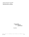
DTMF MICROPHONE
KMC-18/18A
KENWOOD
SERVICE MANUAL
© 1993-2 PRINTED IN JAPAN
851822000(J)972
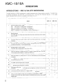
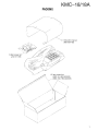
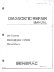
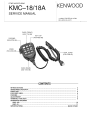
CASE (FRONT)
(A02-1744-0S)
KEY TOP
(K29-4S56-0S)
PACKING
(G53-07;),,-uo I·-~
KNOB
(K24-2004-0S)
CASE (REAR)
(A02-1745-0S)
--------CONTENTS------INTRODUCTIOI\lS
~!~'CONDucTOIi.DATi:::::::::::::::::::::::::::::::::::::::::::::::::::::::::::::::::::::::::::::::::::::::::::::......................
TS LIST .................
......................
2
3
~ ~ ~rE~;7: : : : : : : : : : : : : : : : : : : : : : : : : : : : : : : : : : : : : : : : : : : : : : : : : : : : : : : : : : : : : : : : : ~
TERMINAL FUNCTION
................................................................................. 8
SCHEMATIC DIAGRAM··············································· ......................................................................... 9
~~CC=1188A
...................................................................................................................... .. ................. 10
...............
SPECIFICATIONS ....
:::::::::::::::::::::::::::::::::::::::::::::::::::::::::::::::::::::::::::::::::::::::::::::::::::::::::·BACK··COV·~~
KMC-18/18A
INTRODUCTIONS
II\lTRODUCTIOI\lS --- KMC-18/18A (DTMF MICROPHONE)
The KMC-18/18A is a DTMF microphone for mobile transceivers with a 6-pin modular connector. The KMC-18 is
standard microphone, the KMC-18A, a multi-function one. They have the following features. (In the table
below, indicates that the function is available, and indicates it is not .)
Q
Feature
2
KMC-18
KMC-18A
1
Conforms to MIL-STD-81- C/O/E.
Rain
506.1/Proce. 2, 506.2/Proce. 2, 506.3/Proce.2
Dust
510.1/Proce. 1,51 0.2/Proce. 1,51 0.3/Proce.1
Vibration514.21Proce. 8.10, 514.3/Proce. 1, 514.4/Proce.1
Shock 516.2/Proce. 1.2.3.5, 516.3/Proce. 1.3.4.5.6, 516.4/Proce.1.4
0
0
2
Backlit keyboard
(The KMC-18A has a three-level programmable illumination switching function (bright,
dark, and OFF).
0
0
3
The hook fitting has a switch function, and the on-hook ground wire is no longer
necessary.
0
0
4
The curly cord has an 8-pin modular connector (microphone) and a 6-pin modular
connector (transceiver). It can be replaced easily.
0
0
5
A beep sounds to confirm operation.
(The KMC-18A is programmable to set it ON or OFF.)
0
0
6
DTMF key operation is inhibited while the PTT button is being held down. (The KMC18A is programmable to disable or enable the DTMF key.)
0
0
7
When the DTMF key is pressed, the PTI turns on automatically and the microphone
is disabled.
0
0
8
The hook can be held on or off.
X
0
9
The DTMF code transmission time is variable.
X
0
10
The 4th column tone transmission is variable.
X
0
11
Eight types of DTMF code up to 22 digits (such as telephone numbers) can be stored
in memory.
X
0
12
Connect/disconnect ANI codes up to 17 digits can be stored in memory.
X
0
13
One of the nine operation modes can be selected by combinations of three kinds of
operation function (Auto Dial, Store and Send, and Manual Dial) and the Last Number
Redial function.
X
0
KMC-18/18A
SEMICONDUCTOR DATA
~PD75008-732-3B4
: KMC-18A (lC2)
Pin
No.
Terminal
Name
1/0
1-3
P70 - P72
I
Key data input
4
P63
0
PTT output
5
P62
0
HOOK output
6
P61
0
Backlight: Bright (Output high: Bright is selected.)
7
P60
0
Backlight: Dark (Output high: Dark is selected.)
8
P53
0
DTMF output enable (Output high: Tone is output.)
9
P52
0
Tone select (Output high: Row tone is output.)
10
P51
0
Tone select (Output low: Column tone is output.)
11
P50
0
Microphone mute control (Output high: Mute on)
12
NC
-
+5V
P40 - P43
0
DTMF tone data output
17
Vss
-
GND
18
XT1
I
Open (not used)
19
XT2
0
Open (not used)
20
RESET
I
Reset input (Low: Reset)
21
X1
I
System clock input
22
X2
I
System clock input
23
P33
0
EEPROM clock output
24
P32
1/0
EEPROM address output, data input/output
25
P31
0
Open (not used)
26
P30
0
Open (not used)
27
P81
0
Open (not used)
28
P81
0
2000-Hz/500-Hz beep output
29
P03
I
Open (not used)
30
P02
I
Open (not used)
31
P01
I
Open (not used)
32
POO
I
EEPROM version switching (Open: 1-kbit EEPROM)
33
P13
I
PTT switch input
34
NC
-
+5V
35
P12
I
HOOK switch input
36
P11/INT1
I
Test data input (Low: Input start)
37
P10/INTO
I
Clone data input (High: Input start)
38
NC
-
+5V
39
Voo
-
+5V
P20- P23
0
Key scan data output (Output: Normally low)
NC
-
Open (not used)
13 -16
40-43
44
Function
3
KMC-18/18A
PARTS LIST
" New Parts
Par ts wi tnout Parts No. are not supplied.
Les articles non mentionnes dans Ie Parts No. ne sont pas fournis.
Teile ohne Parts No. werden nicht geliefert.
Ref.
No.
Address
New
Parts No.
Parts
wlllHt%
itr
til
all
Ii
•
'"
RR
Oeser ipt ion
all
%
Jl,
~
10/11
Oesti- Renation marks
(.;J {tilt
i±
KMC-18/18A
1
A02-1744-08
A02-1745-08
CASE(FRtSlNTl
CASE(REAR)
862-0354-08
872-0542-08
872-0543-08
INSTRUCTItSlN MANUAL(ACS)
MtSlOEL NAME PLATE
MISlDEL NAME PLATE
E23-04 26-05
E30-3156-05
E37-0345-08
E40-5190-05
E40-5179-05
TERMINAL< HtSltSlK)
CURL CISlRD
CtSlNNECTING WIRE(2P)
PIN ASSY(13P)
PIN ASSY(2P)
E08-0571-05
E37-0344-08
MtSlDULAR JACK
CtSlNNECTING WIRE(13P)
G02-0739-08
G10-0736-08
G10-0737-08
G53-0753-08
G53-0754-08
SPRING(PTT)
FEL T( MIC)
FELT(SP)
PACKING(PTT)
PACKING(MIC,SP)
H52-0425-08
H52-0426-08
ITEM CARTtSlN 8tSlX
ITEM CARTtSlN BtSlX
J19-1376-15
J19-1511-05
J30-0595-08
MIC HANGER
MIC HANGER SET(ACS)
SPACER(MIC)
K24-2004-08
K29-4856-08
KNtSlB(PTT)
KEY TtSlP
L78-0035-05
L78-0089-05
L78-0036-05
CRYSTAL tSlSC<3.594MHZ)
CERAMIC ISlSC(480KHZ)
CRYSTAL tSlSC(4.19MHZ)
'*
N17-1020-46
N24-3020-41
N39-2050-41
N46-2606-46
N46-4016-46
TtSltSlTHED LtSlCK WASHER(HtSltSlK)
E RING(PTT)
MACHIN SCREW(HtSltSlK)
TAPTTTE SCREW(UNIT)
TAPTITE SCREW(HANGER)
'*
N80-3016-41
TAPTITE SCREW(CASE)
S50-1A.15-05
TACT SWITCH(PTT)
T07-0285-05
T91-0538-05
232-0032-05
SPEAKER
MICRlIlPHISlNE(EMC)
TUBE(CASE)
01
D1
D2
02
D3
1SS184
1SS190
1SS181
1SS190
lSS 18 4
DltSlDE
DHilDE
DItSlOE
DItSlDE
DItSlOE
A
B
A
8
1)3
04
D4
OS
[)6
1SS190
1SS190
155226
155226
1S5190
OItSlOE
DltSlDE
DllIlDE
DI tSlOE
DIlIlDE
A
B
A
A
A
TCl
I"R40872
Ie CTiSlNE DIALER)
B
18
38
?
?
.>
4
4
6
7
CN1
CN2
2A
28
CN3
W1
8
38
10
11
38
28
12
12
13
15
16
3B
18
*
'"
*
*
*
'"
'"
'"
'"
'"
'"
'"
'"
'"
'"
'"
'"
'"
'"
*
'"
Xl
Xl
X2
'"
*
*
'"
A
B
D
17
18
4
2B
2B
'"
L:Scandinavia
K:USA
Y:PX(F ar East. Hawaii)
T:EngJand
E:Europe
Y:AAFES(Europe)
X:Australia
M:Other Areas
8
A
B
A
8
A
A
8
A:KMC-18A
B:KMC-18
P:Canada
it
indicates safety critical components.
KMC-18/18A
PARTS LIST
~
New Parts
Parts without Parts No. are not supplied.
Les articles non mentionnes dans Ie Parts No. ne sont pas fournls.
Teile ohne Parts No. werden nicht geliefert.
Ref.
No.
Address New
Parts No.
Parts
~!llHt%
f:;L
ii:
TCl
IC2
IC2
IC3
TC3
$
ii
*
*
•
Jl.
Description
%
TC35219F
75008GB-732-3B4
NJM7 8 I" 0 8 UA
TC4S584F
X24C01SI
$
IC(DTMF
IC(CPU)
"
RR
m
~/m.
IaJ
Remarks
1J~
A
A
GENERAT~R)
IC(V~LTAGE
Destination
f±
REGULAT~R/
+8V)
TC(SCHMITT TRIGGER)
B
B
A
IC(EEPR~M)
M51943BML
NJM78L08UA
NJM78L05UA
DTC144EK
2SC2712
TRANSIST~R
G4
G4
G5
G5
G6
DTC144EK
DTA144EK
DTA144EK
DTC144EK
DTC144EK
DTGITAL TRANSIST~R
DIGITAL TRANSIST~R
DIGITAL TRANSISmR
DIGITAL TRANSIST~R
DIGITAL TRANSIST~R
A
8
A
8
G7
G7
G8
DTA 144EK
DTC114YK
DTC144EK
DIGITAL TRANSISTIIJR
DIGITAL TRANSIST~R
DIGITAL TRANSIST~R
8
A
B
L:Scandinavia
K:USA
Y:PX(F ar East, Hawaii)
T:England
E:Europe
Y:AAFES(Europe)
X:Australia
M:Other Areas
IC(SYSTEM RESET)
A
A
A
A
B
1C4
IC5
IC6
Gl -G3
G1 -G3
IC(V~LTAGE
REGULAT~R/
IC(V~LTAGE
REGULAT~R/
DIGITAL
+8V)
+5V)
TRANSIST~R
A:KMC-18A
B:KMC-18
P:Canada
Lh
indicates safety
itical components.
5
KMC-18/18A
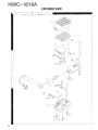
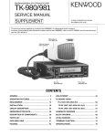
EXPLODED VIEW
A
6
KMC-18/18A
PACKING
--.~
/'
(
/'
\/
/
/
/
)
/
~
/
]
~
/ . 3 Instruction manual
(862-0354-08)
7
KMC-18/18A
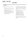
ADJUSTMENT
The DTMF tone deviation has been adjusted at the factory, so does not normally need
to be adjusted.
•
DTMF tone deviation adjustment (for KMCl8/l8A)
1. Remove the three screws securing the back
of the KMC-18/l8A case, then remove the
back.
2. Connect the deviation meter to the
transceiver to be used, then connect the
KMC-18/l8A to the transceiver.
3. Hold down key [§J. The transceiver transmits
the DTMF tone corresponding to key &].
With key [§J still down, adjust semi-fixed
resistor VR 1 on the KMC-18/l8A board to set
the deviation to 2.2 kHz.
4. Put the back of the case on.
•
The KMC-18A allows you to adjust the deviation
using the single tone transmission function.
Perform steps 1 and 2 above, then put the KMCl8A into set-up mode. (To enter set-up mode,
hold down keys [JJ, [3], and
and switch the
power on.)
I*l
Next, press keys [ill, [Q], and
then press the following keys:
Press
Press
Press
Press
Press
Press
Press
Press
00
in that order,
OJ to transmit the Row 1 tone.
IlJ to transmit the Row 2 tone.
~ to transmit the Row 3 tone.
[II to transmit the
[[i to transmit the
[ill to transmit the
[l] to transmit the
[ill to transmit the
Row 4 tone.
Column 1 tone.
Column 2 tone.
Column 3 tone.
Column 4 tone.
Adjust VRl while each tone is being transmitted,
setting the deviation to 1 kHz for the Row 1 tone
(key OJ) and to 1.5 kHz for the Column 1 tone
(key [[i).
8
KMC-18/18A
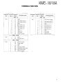
TERMINAL FUNCTION
Connector Terminal Terminal
No.
No.
Name
Terminal function
Connector Terminal Terminal
No.
No.
Name
KMC -18
CN1
1
2
3
4
5
6
7
8
9
10
11
12
13
E
C1
C2
C3
E
R4
R3
R2
R1
E
L2
L1
NC
GND
Key matrix column 1
Key matrix column 2
Key matrix column 3
GND
Key matrix row 4
Key matrix row 3
Key matrix row 2
Key matrix row 1
GND
LED power
LED power
Open (not used)
Terminal function
KMC-18A
CN1
1
2
3
4
5
6
7
8
9
10
11
12
13
E
C1
C2
C3
E
R4
R3
R2
R1
E
L2
L1
NC
LED dimmer control
Key matrix column 1
Key matrix column 2
Key matrix column 3
GND
Key matrix row 4
Key matrix row 3
Key matrix row 2
Key matrix row 1
GND
LED power
LED power
Open (not used)
KMC -18118A
CN2
1
2
E
HKI
GND
Hook SW input
KMC-18118A
CN3
1
2
3
4
5
6
7
8
NC
SB
E
PTT
ME
MC
HK2
NC
Open (not used)
Power supply
GND
PTT
Microphone GND
MIC/DTMF signal output
Hook switch output
Open (not used)
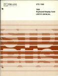
9
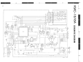
A
o
r-------------------------------------------------------,I
:-:1---------------rn
w,
r - ~f-<>
CN'
,3
nrcc
C3
470P
C4
'3
'2
L2
11
f
.,
10
S
R2
8
)
.3
)
r------"-'~9
470P
C5
470P
Co
470P
I
11
1
LI
~
,.;,) \
l
-'-
C2
I _ 13
c,
I _ 12
Ir
;;-'-0-
[2]
"'0-
n'-o--,
r
T
rno'-o-- lID 0'-0-- rn 0'-0-
~ m,~~,_"f'o.
1
I
I
I
I
..'"
~
~'''''1''''
00
..............
'"'"
ol""h..,
~
'"
00
Gam
ol~l~
t-JI~
li[f L____:::::.
~ :I~ ;I~~~ ~~ ~~
.s
47K
I
L---f--!
HOOK Sw
-'R15
L2
GHTEH
@Ig
[C2
~
'-"lQ
.?.!
11
13
ITw
I
~
.001
R17
1K
Rl B
no
RIG
r
{lli]~
.l.N;;
I
Na
5V
Uj&
I 1.._
~~
I
m
,
Q7
DI-3,
D4, 5
""
DTC114YK
15 5190
155220
II
I_ _ _ _
'T
'
"
MC
ME
s::
!t
-
"
!
I
( "')
C
PfT
E
:;
SB
~NC
I
I
I
I
I
I
I
I
I
I
e33 I1 ·001
R22 0
'1
HK2
.1
f11.j~
I
ii
7
•
5
- -
.0 01
::::I:
m
il
III a:tJ III'~
C34 ;;.001
C28
("')
I CN3
u,
..
3
1,,1'"
en
I
I CN2
~~HK
, 0 E l
5'
, K
~~5
W
II
c-:
~======~==~~==~~~1-t_~_;~--~~IC4
m
C20
l~g
lu
,r
~I'!
-
lK
~: ®
,I,
-- -
I
~
-=--=--=--=--=--=--=--=--=--=--=--=--=-:::.
1
Q3
III
»
1_11
L-
:; I DARKEN
I»
I
r
[!)?o-- m?o- ill?o- ~''',d''"
.,1,
.:
III
~
()
1
C')
:a
l>
s::
•.,
SP
.4=<J""
i
I
__ "I
."
'"
" '"
"
_____ _
______
----------
KMC -
18A
m
::'\
r---------------------------------------------------- I
s:
()
1(;)
I
.....,L
,
Q4
IC1
v+
V+
Xt.lRT
TONEI.!'-'-'---+--+--+--l-
L--~C1
_ _ _---"j C2
L
~f
STi 16
S
R"
R21-"-=:4_ _----'
L - - - --"1 C3
R31-"-"3_ _ __
6"
R4 12
,---.::.:...----"-l x IN
,,,
~
MUTE
XOVT
C4
D2
R3
I-"--'-'_ _ _ _~
10
R,
4
L-
L___
I
I
'''
~
>
R8
47K
~
C3
~
..Leo;;
,V o
°S~
+~
en
I
~
D3
n
::::I:
m
~W C::,
"INOOK
I
1
E
:s:
!t
-
I CN3
,j,
'.7 16V
»
-'-
UTa
;;;;::
OJ
l_ -----.
::-.::-.::-.: -.: -.: -.: -.: -.: -.::-.::-- -1II
---
Q~Q6
~ ;;
7K
R7 .
22K
:!=::;~
.....,L
~
",.
N/C 18
OJ
.............
~INC
~
- 1
I
I
HK2
Me
n
•
~IME
;. :TT
I
C12 " . 001
o r
-
-c
l>
SB
0 1 NC
I
I
"-
.
LN
N
r
R"
:')
u
,h u~
L. _ _ _ _ _ _ _ _ _ _ _ _ _ _ - ,
IC2
'"
I C3
NJM78L08UA
","m
Q1- 3
Q4.7
QS. b. 8
TC4SS84F
2SC2712
OTA144EX
OTC144EX
01.3
1551 64
02
04
15516 1
1 55190
I
II
I
I
I
I
I
I
C')
I
1
220
_ _
I
"1
E
Q8
I
=
:s:
l>
5P
Mle
L'J-l II IIII
~
I
I
I
L__________________________________________________ ___________
KMC _ 18
....1
A
KMC-18/18A
SPECIFICATIONS
Element Type
Impedance
Sensitivity
Voltage required
Current drain
Operating temperature range
Output impedance
DTMF tone output level
Frequency stability
Tone distortion
High group tone output (relative to low group)
:010 mm ECM
: 1 KQ ± 30%
: -64 dB ± 3 dB at 1 kHz (0 dB = 1 v//J.Bar)
:DC 13.8V±20%
: 45 mA or less (Back Light: bright, Beep: OFF)
: 65 mA or less (Back Light: bright. Beep: ON)
: -300C - +60 0 C
:600 Q
: 5 mV ± 1.0 mV
:± 1.5%
: 10% or less
: + 1 dB or more, +3 dB or less
KENWOOD CORPORATION
Alive Mitake. 2-5. Shibuya l-chome. Shibuya-ku. Tokyo 150. Japan
KENWOOD U.SA CORPORATION
COMMUNICATIONS & TEST EQUIPMENT GROUP
P.O. BOX 22745. 2201 East Dominguez St.. Long Beach. CA 90801-5745. U.S.A.
KENWOOD ELECTRONICS DEUTSCHLAND GMBH
Rembrucker Str. 15. 6056 Heusenstamm. Germany
KENWOOD ELECTRONICS BENELUX N.V.
Mechelsesteenweg 418 B-1930 Zaventem. Belgium
TRIO-KENWOOD FRANCE SA
13. Boulevard Ney. 75018 Paris. France
TRIO-KENWOOD U.K. LIMITED
KENWOOD House. Dwight Road. Watford. Herts .. WDl 8EB United Kingdom
KENWOOD ELECTRONICS NEDERLAND B.V.
Amsterdamseweg 35. 1422 AC Uithoorn. The Netherlands
KENWOOD LINEAR S.pA
20125. Milano-via Arbe. 50. Italy
KENWOOD ESPANA SA
Bolivia. 239-08020 Barcelona. Spain
KENWOOD ELECTRONICS AUSTRALIA PTY. LTD.
(A.C .N. 001 499074)
P.O. Box 504. 8 Figtree Drive. Australia Centre. Homebush. N.S.W. 2140. Australia
KENWOOD & LEE ELECTRONICS, LTD.
Unit 3712-3724. Level 37. Tower one Metroplaza. 223 Hing Fong Road. Kwai Fong. N.T.. Hong Kong
KENWOOD ELECTRONICS CANADA INC.
6070 Kestrel Road . Mississauga. Ontario. Canada L5T 158