1
I
Manual Part No. 75239
•
DIAGNOSTIC REPAIR
MANUAL
•
Air-Cooled
Recreational
hicle
Generators
••
GENERAC
Printed in I ! .S .t\ .
f\.
FOREWORD
This DIAGNOSTIC REPAIR MANUAL has been prepared especially for the purpose of familiarizing service personnel with the operational analysis,
troubleshooting, testing, disassembly and repair of the Series NP45G, NP55G and
NP65G recreational vehicle generators.
Keep the Manual In a safe place and refer to it as often as necessary. The
Manual contains important technical data and should be referred to whenever the
need for such Information arises.
Every effort. has been expended to ensure the information In the Manual Is
both accurate and current. However, the manufacturer reserves the right to
change, alter, or otherwise Improve his product at any time without prior notice.
•
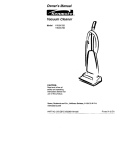
TABLE OF CONTENTS
Page
Page
Wiring Diagram and Electrical Schematic ................... 11
Troubleshooting
Exploded View of Sheet Metal. .. ... .......... ....................26
Introduction..................... ... ......... ... ... ..... ..................... 12
Exploded VIew of Base and Pulley ............. ................28
Problem No. 1- Engine Won't Crank .. ........................ 13
Exploded View of Generator and Panel. .... ..... ............ 30
Problem No. 2- Engine Cranks, Won't Start ............... 15
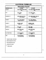
Electrical Formulas ..................................................... 32
Problem No. 3- Engine Cranks and Starts. Shuts
Spectflcatlons ........ ............ .. ............... ... ............. .. .... ... 33
RV Generator
Down When Start/Stop Switch Is Released ............... 17
Problem No.4- Engine Starts Hard, Runs Rough ...... 18
Generator Fundamentals
Problem No.5- Engine Won't Shut Down ........... ...... . 18
Introduction .................................................................2
Problem No. 6- Loss of Generator a-c Output ............ 19
Electro-Magnetic Induction ..... .................. .................. 2
A Simple a-c Generator ...... ......... .... ........ ................. ..2
Engine Troubleshooting
A More Sophisticated a-c Generator......... ........... ·· ·····'
c
Generator Block Diagram ............... .... ........................ 3
Checking Engine Compression .................................. 23
....................................................................... 23
~
Check Engine Ignition ............................ .............. ...... 23
Introduction to Troubleshooting
Check Carburetlon .................. .......................... ..... .... 23
Introduction ... ............................. .................................4
Other Problems that Might Affect Engine Operation .. 23
Tools and Test Equlpment .......... .. ......................... ..... 4
•
Rotor Rotational Speed ............................................... 4
Adjustments
RelaUonshlp of Voltage and Frequency ... ..•................ 5
General ... .................................................................... 24
Generator a-c Connection System ............... ...............5
Engine Governor Adjustments ................................... 24
Effects of Engine Power ................. ................. ........... 5
Voltage Regulator Adjustment... ... .......................... .... 24
Effects of Din and Moisture on RV Genef'Dtors ... ....... 5
Automatic Choke Adjustment ............................. .. ...... 25
Operational Analysis of D-C Control System
Introduction ......................... ........................................6
Circuit Condition- Engine Shut Down ......................... 6
Clrcult Condition- Engine Cranklng ............ ............ ..... 6
Circuit Condition- Startup and Running ...................... 7
Circuit Condition- Normal Shutdown .................... ... .... 8
Insulation R slsta ee 1 sts
General ..... .. .......... .. ........................ .. ..........................9
The HI-Pot Tester ..................................... ...................9
Testing Stator Insulation .............................................9
Testing Rotor Insulation for Breakdown ...................... 10
Cleaning the Generator .... ........................................... 10
Drying the Generator ................... ........................... .... 10
•
1
GENERATOR FUNDAMENTALS
Introduction
A
It has long been known that a relationship·exlsts between
magnetism and electricity. Revolving field a-c generators
depend on this relationship for their operation. The service technician must understand that relationship. This
section of your DIAGNOSTIC REPAIR MANUAL will
familiarize you with the basic fundamentals of generator
operation.
00026
Electro-Magnetic Induction
B
A
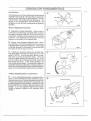
Magnetism Creates Electricity: - When a wire or
coil of wire is moved through a magnetic field, an electrical voltage is created in that wire. If the ends of the wire
are joined to complete a circuit, electrical current will flow
in the wire. The direction that current flows in the wire
depends on the polarity of the magnetic field.
B Current Flow Creates a Magnetic Field: - Whenever electrical current flows through a wire or coil of wire,
a magnetic field is created around that wire. The strength
of the field depends on the amount of current flow and
the number of calls or loops In the wire.
00027
C A simple a-c generator consists of a spinning magnetic field called a ROTOR and stationary coli 01 wire
called a STATOR. As the Rotor spins. Its lines of magnetic force cut across the stationary Stator. When the
ends of the Stator winding are connected across a load
(such as a light bulb) to complete the circuit, current will
flow through the circuit In this simple ge.r.arator, the
Rotor is a pennanent magnet The amount of \'gtfage and
current flow induced into the Stator windings depends on
(a) the Rotor's magnetic field strength, (b) Rotor rotational
speed, and (c) the number of turns of wire in the Stator.
C
A More Sophisticated a-c Generator
1._ooo_
2s_ _ ____:__ _ _ _ _ _ _ _ _ __ _ J
D
A more sophisticated generator is equipped with a
Stator a-c power wlrvUng and a Stator excitation winding.
Regulated direct a,..
'Om the excitation winding flows
through carnon br ~... .
IVch slide on metaJIIc slip rings .
and then through the Ro r windings. Regulated current
flow through the Rotor creates a regulated magnetic field
strength. In turn, the regulated magnetic field strength
\nduces a regulated voltage Into the stationary Stator :
winding.
D
00024
2
PO WElt WINO/NO
•
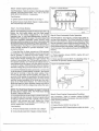
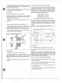
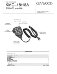
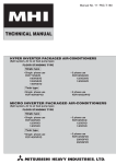
Generator Block Diagram
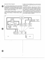
2. Stator a-c Power Winding :- The a-c output from this
winding Is used to supply electrtcal power to connected
electrical loads.
E The Rotor (spinning field) Is driven by the engine,
through a belt and pulley arrangement to maintain a fixed
operating speed. The Rotor's magnetic field cuts across..
(a) a Stator a-c power winding, (b) a Stator excitation
winding, and (c) a .stator battery charge winding, to
Induce a voltage Into those windings.
3. Excitation Winding:- OUtput from this winding Is
delivered to an Electronic VC~lhge Regulator, where Ills
rectified and, based on a-c power winding sensing signals, regulated. The regulated, rectified current flows
through the brushes and slip rtngs and Into the Rotor
windings. Because the current flow Is regulated, the
Rotor's magnetic field strength Is regulated. In tum, because the field strength Is regulated, the voltage Induced
into the Stator windings Is regulated.
1. Stator Battery Charge Winding: Rectified direct
current output from this winding Is delivered to the generator's 12-volts battery, to maintain battery state-ofcharge.
E
Voltage
Regulator
12 VOLTS
BATTERY
•
BATTERY
CHARGE
Customer
Load
. . . . . .-~....
~Connections
Stator
Battery
Charge
Winding
Stator
Excitation
Winding
Stator a-c
Power
Winding
,,
I
..........................
DIODE
Stator a-c
Power
Winding
' .....
I
,,
.1'
I
/
I
' ,
I
I
''
I
I
'
I
'
.
_, "-~ ...... Magnetic Field
/
/
/
/
/
Revolving
Field
(Rotor)
Engine
00023
•
3
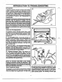
INTRODUCTION TO TROUBLESHOOTING
Introduction
A
A typical RV generator set does not have a large number
of parts. However, the parts are expensive. For that
reason, a parts replacement method of troubleshooting Is
not cost effective. A basic understanding of generators is
essential to good troubleshooting, i.e., why they behave
or don't behave as they should. This section will Introduce
the technician to some of the fundamentals of
troubleshooting.
DANGER I: Recreational vehicle generators produ
extremely high and dangerous voltages. Use exreme care when working on or around the gener
tor. Contact with live wires and terminals will cau
xtremely hazardous and possibly lethal electrical
hock. Only personnel who have been thoroughl
rained In the maintenance of RV generators shoul
ttempt to troubleshoot, test, repair or service age
rator.
00031
B(iiiiiiiiiiiiiiiiiiiiiiiiiiiiiiiiiiiiiiiiiiiiiiiiiiiiiiiiiiiiiiiiiiiiiiiiiiiiiiiiiiiiiiiiiiil
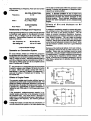
Tools and Test Equipment
The generator service technician should have a well
stocked tool box havtng a good selection of common hand
tools. Such a tool box shoutd contain wrenches fn both
metric and english sizes. Also recommended Is a good
nut driver set.
A Vort-Ohm-MIIIIamrneter:- An accurate volt-ohm-milliammeter (VOM) is essential for the troubleshooting and
testing of generators. Simply having a VOM Is not
enough. The technician must understand electricity, must
be famiHar with electrical circuits, must be able to read
wiring diagrams/electrical schematics, and must know
how tlo use the VOM.
8
c
Frequency Meter:- This test device permits the gen-
erator's a-c output frequency, in HERTZ or CYCLES PER
SECOND, to be read. Measurement of frequency is required for precise adjustment of engine-generator speed.
Also see ROTOR ROTATIONAL SPEED.
·C
Insulation Resistance Tester:- Also called a •HI-
POT•, this device pennHs generator Stator and Rotor
winding Insulation to be tested for breakdown. Use lhe
HI-Pot tester to test resistance between parallel stator
wfndfngs, between isolated windings, and the resistance
of all wfncftngs to ground. See also EFFECTS OF DIRT
AND MOISTURE ON GENERATORS.
NOTE: An electrical LOAD BANK Is also recommended for generator testing and adjustment. Th
Load Bank permits a known electrical load to be a
llect to the generator, for the purpose of testlnglad
·ustln unit o eratlon under load.
glne driven through a belt and pulley arrangement Such
a 2-pole Rotor must be operated at 3600 rpm to supply
an a~ frequency output of 60 Hz. The belt and puUey arrangement provides a speed reduction, so that engine
speed can be reduced whHe driving the Rotor at Its requtred operating speed. The following fonnulae apply
Rotor Rotational Speed
The generator's revolving field on Series NP45G, NP55G
and NP65G generators Is a 2-pole type, having a single
north and a single south magnetic pole. The Rotor Is en
4
.
--~---------.
-~---------------------------------
not be able to handle loads wtthln the generator's rated
capacity. Problems with generator a-c output are oftencaused by an engine problem.
when determining a-c frequency, Rotor rpm and number
of Rotor poles.
Frequency
D
rpm X No. of Rotor Poles
2x60
OTE: A shorted condition In one or more con
ected electrical loads or In generator windings ca
ramatlcally Increase the power demands on th
riving englhe. Such shorted conditions ma
resent the same symptoms as an underpowered
2 x 60 x Frequency
No. of Rotor Poles
RPM=
n lne.
Effects of Dirt and Moisture oh RV
Generators
2 x 60 x Frequency
Rotor Poles=
rpm
If moistUre Is permitted to remain In contact wfth generator windings. some of that moisture may be retained In
cracks and voids of the winding Insulation. This will
cause a reduced Insulation resistance. However.
prolonged exposure to moisture resistance of stator and
rotor winding Insulation. Dirt can make the problem
worse, since It tends to hold moisture Into contact with
windings. Salt (as from sea air) also makes the problem
worse, since salt wHI absorb moisture from the air. When
salt and moisture combine, they fonn a good electrical
conductor.
Relationship of Voltage and Frequency
Engine govemed speed and a-c vottage are adjusted with
no elecb'lcal loads appDed to the generator (no-load).
That Is, the a-c voltage Is set at a fixed ratio to a-c
frequency. Recommended frequency and vottage settings are as follows:
Set Frequency to:
set vonage to:
60.5 to 63.5 Hz
121 to 127 voltsa
*Line-to-Neutral Vohage
~enerator
Because of the detrimental effects of dirt and moisture,
the generator should be kept as clean and as dry as
possible. Stator and rotor windings should be tested
periodically, using an Insulation resistance tester {HI-Pot
or megohmmeter). HInsulation resistance Is excessively
low, drying may be required to remove moisture. After
drying, a second test of Insulation resistance Is still low
after drying, replacement of defective windings may be
necessary.
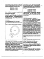
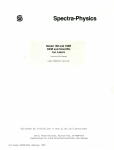
a-c Connection System
0 Series NP45G, NP55G and NP65G RV generators
are equipped with dual Stator a-c power windings. These
windings may be connected In parallel to provide a 120votts a-c ou1put as shown. Note that customer loads of
up to 30 a-c amperes may be connected across Wires T1
(red) and T2 (white); loads up to 20 a-c amperes across
wires T2 (white) and T3 (black).
E The generator's a-c output leads may be reconnected
In series, to supply a dual voltage (120 and/or 240 volts)
a-c output. When this Is done, connect 240 volts a-c
loads across T1 (red) and T3 (black); 120 volts aaoss T1
(red) and T2 (white) or T3 (black) and T2 (white). T2 Is
the neutral wire.
D
~~:m1·'1I
BLACKf
Effects of Engine Power
The generator engine must develop suffldent power to
operate the generator under varying electrical loads. The
greater the wattage (amperage) demands ot connected
electrlcalloads, the greater the engine power needs. As
a general rule, approximately 2 engine horsepower Is
needed tor each 1000 watts (1.0 kW) of generator power
output.
.....
1:10,_
~njJ
WHITE
.
CB1:JD-c:ll<ullll-.
Clll;lD _ _ _ IH"')((I
NOTE;Ito-.10~
.120 - -
E
H the generator's wattage/amperage capacity Is exceeded, engine power may not be adequate to handle
the Increased load. The result will be a decrease In
engine rpm, a corresponding decrease In generator a-c
output voltage and freqUency, and lntemal generator
overheating.
A badly worn engine, one that has lost compression, or
one with defective fuel, tgniUon or air Intake system may
5
:10-"" NPa0
OAOU<DtD
NtUTAAL
.. 201""9-1""•:5GINI'5501
r
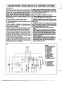
OPERATIONAL ANALYSIS OF D-C CONTROL SYSTEM
Introduction
This section of your Manual is Intended to famfllartze the
reader wlth how the RV generator's d-e control system
functions. The d-e control system provides the means to
obtain engine cranking, engine Ignition and fuel flow. carburetor choking, field boost and battery charging. H
problems with any of these functions are encountered,
the technician must have a wortdng knowledge of how the
system operates.
5. Banery voltage Is available to the Battery Charge Rectifier (BCR), via Wire #13, 15 amp Fuse (F1 ), Wire #15,
and to a Battery Charge Rectifier (BCR). However, BCR
diode action Inhibits current flow.
ClrcuH Condition- Engine Cranking
B
When the StartJStop SwHch is held at Hs START posi-
tion, the following sequence of events occurs:-
1. Start/Stop Switch closure connects the Control Relay
(CR2) and the Starter Contactor (SC) actuating coils to
frame ground.
Circuit CondHion- Engine Shut Down
A
With engine stopped, the circuit condition may be
described as follows:
2. The Starter Contactor (SC) energizes and Its contacts
1. Battery voltage is available to the nonnally-open
close to deliver battery voltage to (a) Starter Motor (SM)
and (b) a Choke Solenoid (CS) and (c) a Choke Module
(CM). The folloWing events then occur:
a. Start'r Motor (SM) energizes and the engine
cranks.
·
b. Battery voltage is delivered to the Choke Module
(CM). via Wire 16·, the Choke Solenoid coil, and Wire
90. Choke Module (CM) actfon opens and closes
this cfrruit to ground at a rate dependent on ambient
temperature, to energize and de-energize the Choke
Solenoid. Choke Solenoid (CS) opens and closes
the carburetor choke. ·
c. Battery voHage delivered to the Choke Module
(CM) is delivered to the generator Rotor windings via
a Field Boost Resistor and Diode (housed in the
Choke Module), Wire 4 and the Rotor brushes and
slip rings. This Is field boost
Starter Contactor (SC) contacts. The contacts are open
and the drcult is Incomplete.
2. Battery voltage is available through a 15 amp Fuse (F1)
and to the normally open contacts of Control Relay (CR 1).
These contacts are open and the circuit is Incomplete.
3. Battery voltagte Is available through Fuse (F1 ), through
the normally-closed contacts of Control Relay (CR1 ).
through the Starter Contactor (SC) coli, and to the
Start/Stop Switch (SW1 ). However, the Switch contacts
are open and the circuli is incomplete.
4. Battery voltage Is available through Fuse (F1), through
the Control Relay (CR2) actuating coil, and to the
Start/Stop Switch (SW1 ). However, the Switch contacts
are open and the circuit is incomplete.
A
LEGEND
----------------~~--+-+--
6
________________________
_:_
______
~~---~~~-----------
----
~--·-
d. Battery voltage Is delivered through a diode
(housed In the Choke Module) and to the Wire 14 circuit. Wire 141s now electrically hot, to operate (a) a
Fuel Pump (FP), (b) a Choke Heater (CH), and (c)
an •engine Run• lamp on the optional remote panel.
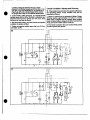
Circuit Condition- Startup and Running
C When engine fires and starts, the operatorwUI release
the Start/Stop Switch. Circuit condition may then be
described as follows:
3. Control Relay (CR2) energizes, i1s nonnally-closed
contacts open and the Wire 18 clrcuh Is effectively isolated from frame ground. Ignition ~n now occur, since
that circuit Is now open to ground.
1. When a-c output from the generator's Battery Charge
Wlndtng reaches approximately 9-12 vohs a-c, Control
Relay (CR1) energizes and Its normally open contacts
ctose, to deliver battery voltage to the Wire 14 circuit (Fuel
Pump and Choke Heater adlons continue).
4. With automatic choking, and with fuel flow and Ignition
available, the engine will start.
2. The Starter Contactor (SC) and Control Relay (CR2)
circuits to ground are opened.
5. Engine oil pressure buHdup opens the Low 011 Pressure Switch (LOP).
8
------------------
:''(f'f'
'.•':~Ul
I
.,
....
,
c
'------4t---::!----d'\.P-!! ____.,_ !!!----~_.,_
_
a;
___;;.;.._.............;;__~
~---------------------~-----------7----------------------------------~
3. Starter Contactor (SC) de-energizes and Its contacts
5. Stator Batlery Charge Winding (rectified) output ls
delivered to the generator battery.
open to eflect the following:a Starter Motor (SM) de-enertzes and aanking
ends.
b. ca·rburetor choking terminates.
c. Field Boost ends.
d. Power to the Wire 14 drrult through the Choke
Module ends.
Circuit Condition- Normal Shutdown
D Closure of the Start/Stop Switch (SW1) to Its STOP
position grounds the engine Ignition circuH. ignition terminates and the engine shuts down. As engine speed
decreases, Low 011 Pressure Switch (LOP) closure maintains the Ignition ground condition.
4. Control Relay (CA2) de-energizes and its normallyclosed contacts close.· However, the ignition circuit to
ground is held open by Low 011 Pressure Switch (LOP)
action and engine Ignition continues.
D
a:
"'
~--~-~~~---.-
;:
8
0
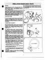
INSULATION RESISTANCE TESTS
Ge'neral
Refer to EFFECTS OF DIRT AND MOISTURE ON RV
GENERATORS (Page 5). The resistance of rotor and
stator windings should be tested periodically, using a
•HI-Pot• resistance tester.
·
4. Tum tester switch ON and check that Pilot Lamp Is ON.
Then, set Voltage Selector Switch to 2000 volts. Observe
the BREAKDOWN tamp, watt one second. then tum
tester switch OFF.
A
CAUTION!: When using the HI-Pot (Insulation Resls·
ance) tester, follow the tester manufacturer's Inructions carefully. Improper use of the tester can
H In sertous damage to the generator. Do not
pply voltage In excess to those recommended I
his Manual to Stator or Rotor wlndln s.
The HI-Pot Tester
A The HI-Pot tester shown Is only one of many brands
avaDable. It Is equipped with an On/Off switch. The pilot
Lamp glows to Indicate tester power Is available. The
breakdown lamp wiD light to Indicate failure of the winding
betng tested.
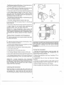
Testing Stator Insulation
B
Gain Access to Stator Leads: Remove screws that
r:etaln the front panel to the panel housing. Remove the
generator cover. . Inside the panel housing, locate the
Electronic Voltage Regulator and the 3D-amp Circuit
Breaker (CB1 ).
B
C
Disconnect Stator Leads: Disconnect Stator a-c
output wires 11 and 22 from the Electronic Voltage
Regulator terminals. Disconnect Stator Wire 33 from the
3D-amp Breaker (CB1 ). Separate wires 22 and 44 a1 their
Junction. Finally. disconnect Stator Exdtation Wiridlng
Wires 2 and 6 from the Electronic Voltage Regulator
terminals.
ANGER!: Follow the Instructions carefully. ·Wir
ennlnal ends must not be touching any pan of th
enerator when HI-Pot voltage Is applied. · Do not
xceed the recommended voltages. Apply voltag
o wlndln s for a maximum of 1 second on •
00036
c
Test All Stator Windings to Ground: Connect tennlnal
ends of Stator a.c output Wires 11, 22, 33, 44, 2 and 6
tightly together. Make sure no tennlnal end Is In contact
with the generator frame. Then proceed as follows:
STATOR ASSEMBLY
1.Connect REO test lead of Hi-Pot tester to joined terminal ends of Wires 11, 22, 33, 44, 2 and 6.
2. Connect the BU\CK test lead to a clean, painted trame
ground (on generator Stator can).
3. Tum HI-Pot tester switch OFF. Then plug tester Into a
120 volts wall socket and set Its Voltage Selector SwHch
to 500 volts.
AUTIONI: IN STEP 4, DO NOT APPLY VOLTAG
ONGER THAN ONE MINUTE.
9
D
Test Between Isolated Windings:- To test between isolated Stator windings, proceed as follows:
1. Connect RED lead of HI-Pot tester to terminal end of
Wire 11, BLACK test lead to Wire 2 terminal end.
2. Tum tester switch ON and check that Pilot Ught Is ON.
3. Set Voltage Selector Switch to 1500 volts- APPLY
VOLTAGE FOR ONE SECOND ONLY. Observe tester
Breakdown lamp. Tum tester switch OFF and reset Voltage Selector Switch to 500 volts.
Test Between Parallel Windings:- Test between parallel Stator windings as follows:
1. Set tester Voltage Selector Switch to 500 volts.
2. Connect tester RED test lead to Wire #11 , BLACK test
lead to Wire 33.
E
3. Tum tester switch ON and check that Pilot Light is ON.
4. Apply voltage for one second while observing the
Breakdown lamp. Then, tum tester switch OFF.
RESULTS: If tester Breakdown lamp comes ON
during any one second test, clean and dry the stator.
Then, repeat the breakdown test. If Breakdown lamp
Illuminates after drying, replace the Stator Assembly.
Testing Rotor Insulation for
Break~ own
D Remove generator cover to gain access to the Rotor
slip rings and brushes.
E
Remove all wires that connect to the Brushes. Then,
lest Rotor insulation as follows:
CAUTION!: Do NOT use a forceful spray of water to
clean generator. Some of the water will be retained
on generator windings and will cause serious
roblems.
1. Connect tester RED test lead to the positive(+) Rotor
slip ring (nearest the Rotor bearing).
2. Connect BLACK test lead to a clean frame ground.
3. Turn tester switch OFF.
Drying the Generator
4. Plug tester into a 120 volts wall socket.
6. Tum tester switch ON and check that Pilot Light Is ON.
1. Open the main circuit breaker or main line switch. NO
ELECTRICAL LOADS MUST BE CONNECTED TO
GENERATOR WHILE DRYING.
7. Set Voltage Selector Switch to 1250 volts and observe
the tester breakdown lamp. Then. turn tester switch OFF.
2. Remove the generator cover (see Illustration "8" on
previous page).
5. Set Voltage Selector Switch on tester to 500 volts.
3. Disconnect Wire #4 from the Electronic Voltage
Regulator.
RESULTS:- If tester breakdown lamp Ilium fates
during the 1 second test, drying of the generator may
be necessary. After drying, repeat the HI-Pot test. If
Rotor windings fall the second test (after drying),
replace the Rotor assembly.
4. Provide an external source to blow warm, dry air
through the generator. Do NOT exceed 165' F. (65. C.).
5. Start the engine, let It run for 2 to 3 hours.
6. Stop the engine and retest Stator and Rotor windings.
Cleaning the Generator
Removed caked on or greasy dirt with a soft brush or a
clean, damp cloth. A vacuum system may be used to pick
up loosened dirt. Loose dust and dirt may also be
removed using tow pressure, dried air (25 psi maximum).
10
~----.
·-----
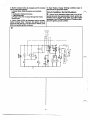
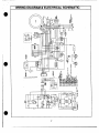
WIRING DIAGRAM & ELECTRICAL SCHEMATIC
·---------
:~~~
: ~
:
I
1
I
1-8
..
.,..
:
!•
'e:-
..
...
o6
I
I
I
I
'----------·
I
e
11
TROUBLESHOOTING THE RV GENERATOR
Introduction
The service technician can use this troubleshooting guide
to determine the cause of existing problems. Six common
problems are covered in this section. Problems are not
ananged in any particular sequence.
The first step In troubleshooting is to Identify your particular problem. When you have Identified your problem,
locate that problem In the troubleshooting guide on this
page. When working your way through the step-by-step
procedure for that problem, start at Step 1 and follow
through the step-by-step procedure. Each step Is arranged in a definite sequence, from the more probable/easiest to check to the less probable/more complex
to check. When the cause of the problem is found and
corrected, stop the test.
Follow the step-by-step procedures carefully. After completing each test, read the TEST RESULTS. Some test
results may instruct you to skip certain steps and proceed
to a new step number.
Problem No. 3- Engine Cranks and Starts,
Shuts Down When Start/Stop Switch is
Released
Step 1- Check Engine 011 Level
Step 2- Check 011 Pressure Switch
Step 3- Check Control Relay CR1
Step 4- Check Stator Battery Charge Windings
Step 5- Check Resistor R 1
Problem No. 4- Engine Starts Hard, Runs
Rough
Step 1- Check Engine Ignition System
Step 2- Check CarburetJon
Step 3- Check Engine Compression
Step 4- Test Automatic Choke
Problem No. 1- Engine Won't Crank
Problem No.5- Engine Won't Shut Down
Step 1- Check 15 amp Fuse F1
Step 1- Check Start/Stop Switch
Step 2- Check Battery
Step 2- Check Wire #18 & #0
Step 3- Check Starter Contactor SC
Step 3- Check Engine Ignition System (I.S.D.)
Step 4- Check Starter Motor SM
Problem No. 6- Loss of Generator a-c Out-
Step 5- Check Start/Stop Switch SW1
put
Step 6- Check Control Relay CR1
Step 1- Check Circuit Breakers CB 1/CB2
Problem No. 2- Engine Cranks, Won't Start
Step 2- Check Vehicle Wiring
Step 1- Check Fuel Quantity
Step 3- Check a-c Voltage and Frequency
Step 2- Check Fuel Shutoff Valves
Step 4- Check Load Voltage and Frequency
Step 3- Check Fuel Flow
Step 5- Check/Adjust Engine Govemor
Step 4- Check Fuel Filter
Step 6- Check Field Boost Circuit
Step 5- Check Fuel Pump
Step 7- Check Stator Excitation Windings
Step 6- Check Engine Ignition System
Step 8- Check Stator a-c Power Windings
Step 7- Test Choke Module
Step 9- Check Rotor (Aeld) Circuit
Step 8- Check Automatic Choke Operation
Step 1
Step 9- Check Engine Compression/Condition
Step 11- Check/Adjust Voltage Regulator
o- Check Voltage Regulator Sensing
o- Test Control Relay CR2
Step 1
12
,1
TROUBLESHOO.TING GUIDELINES
Problem No.1- Engine Won't Crank
Step 1- Check 15 amp Fuse F1
Step 3- Check Starter Contactor SC
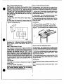
Test Procedure: Remove Fuse F1 from generator panel
and Inspect fuse element. Hnecessary, use a Volt-Ohm-
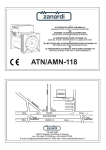
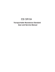
Test Procedure:· Starter Contactor operation may be
tested as follows:
Milliammeter (VOM) to ch~ fuse for continuity.
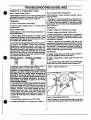
1. See Figure 1. Connect the positive(+) test lead of ade voltmeter to the Wire 56 terminal of the Starter Contac-
Test Resutts:A. Fuse F1 checks GOOD: Go to Step 2
B. Fuse F1 Is open: Replace Fuse F1. If engine cranks
tor. Connect the meter negative (-) test lead to a ~an
frame ground. The voltmeter should Indicate batter¥~
age (12 volts d-e).
normally STOP.
Test Results:
Step 2· Check Battery
A. Battery voltage NOT Indicated: Go to Step 6
Test Procedure:- Perform the following checks/tests on
the generator battery:
B. Battery voltage was Indicated:
Continue test
I
1. Inspect battery terminals (posts) and cables. Cable
clamps and connections must be clean and tight Clean
and/or tighten cable damps and connections
sary: Replace any defective cables.
as neces-
2. Use an automotive type battery hydrometer to test bat·
tery STATE OF CHARGE. Follow the hydrometer
manufacturer's Instructions carefully. Write down the
specific gravity of the electrolyte flufd in each battery cell.
Write down the specific gravHy reading of each cell as the
reading Is taken. Return the electrolyte fluid to the cell
from which It was removed. If the hydrometer used does
not have a percentage of charge scale, compare the readIngs obtained wHh the following:
SPECIFIC GRAVITY
PERCENT OF CHARGE
10~o
1.260
1.230
75o/o
1.200
50°/o
25°/o
1.170
2. Connect the positive (+) test lead of a d-e voltmeter to
the Wire 16 terminal stud of the Starter Contador; connect negative(-) test lead to a dean frame ground. Zero
volts should be Indicated.
3. With d-e voltmeter still connected to the Wire 16 terminal stud and frame ground, disconnect Wire 17 from Its
terminal stud on Starter Contactor. Connect a Jumper wire
from the Wire 17 terminal stud (on Starter Contactor) to
a clean frame ground. The d-e voltmeter should Indicate
battery voltage and engine should aank.
Test Results:
A. Battery voltage GOOD and engine cranks, but wiD not
crank with Start/Stop Switch: Go to Step 5
B. Battery voltage GOOD, engine does NOT crank: Go
to Step4
C. Zero battery voltage with 1umper wire conneded and
engine does not aank: Replace Starter Contactor SC.
H necessary, use an automotive type battery charger to
recharge the battery to a 1000/o state of charge.
Figure 1. Starter Contactor SC
DANGER!: Storage batteries give off EXPLOSIVE
hydrogen gas while charging. Completely remov
he battery from the vehicle before attempting t
recharge lt. Charge the battery only In a well ventt
lated space where explosive gases cannot accumulate and present the danger of explosion. Do not permit smoking, open flame or sparks In the vicinity
· lie char In a batte •
3. If the difference In specific gravHy between the highest
and lowest reading cell Is 0.050 (50 points) or greater, the
battery Is nearing the end of its useful life and should be
replaced. However, If the lowest reading cell has a
specific gravity of less than 1 .200, recharge the battery
and then repeat the specific gravity test. If, after chargIng, the difference between the highest and lowest readIng cell Is still 0.050 (50 points), replace the battery.
Test Results:-
Step 4- Check Slaner Motor SM
A. Nonnal engine cranking oCa.Jrs: STOP tests
Test Procedure:- Conned a jumper cable to the large
battery cable terminal stud (Wire 13) of the Starter Con-
B. Battery checks GOOD, no cranking: Go to Step 3.
13
tactor and to the cable terminal on Starter Motor. Engine
should aank.
2. Connect a jumper wire between the Start/Stop Swttch
Wire 17 terminal and a clean frame ground connection.
Test Results:
Engine should crank and start. Disconnect Jumper wire to
tennlnate cranking when engine starts. To stop the engine, connect jumper wire to Wire 18 terminal of
Start/Stop Switch and to frame ground.
A. Engine aanks nonnally but does not crank when using
the Start/Stop Switch: Go to Step 5.
~-
Engine does NOT crank: Replace Starter Motor SM
TeS1 Results:
C. Engine aanks normally with jumper cable and with
Start/Stop Switch: STOP tests.
A. Engine cranks, starts and shuts down normally when
using jumper wire, but not when using Start/Stop Switch:
Replace Start/Stop Switch.
B. Engfne will not crank when using Jumper wire: Go to
Step 6.
C. Engfne cranks and stops nonnally when using jumper
wire and with Start/Stop Switch: STOP tests.
Step 6- Check Control Relay CR1
NOTE: See WIRING DIAGRAM & ELECTRICAL
SCHEMATIC on Page 11. Two different types of Con~rol Relay CR1 are used on the NP series generators,
Identified In the Wiring Diagram as "CR1" and "AI~ernate CR1". Also see Figures 4 and 5.
NOTE: For Staner Motor SM testing and repair 1
structlons, refer to ENGINE SERVICE MANUAL.
Test Procedure:- See Figure 4 or 5. Test the Relay as follows:
·
1. Connect the positive(+) test lead of a d-e voltmeter to
CR1 tennlnal12 (Wire 15 tennlnaJ); connect the negative ( \
(-)test lead to a clean frame ground. Meter should Indicate battery voltage. If alternate CR11s Installed, connect
meter positive (+) test lead to Relay tennlnal 9 (Wire 15
terminal).
Step 5· Check Stan/Stop SwHch SW1
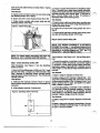
Test Procedure:- See Rgure 3. Test the Start/Stop
Switch as follows:
1. Set a Volt-Qhm-MOIIammeter (VOM) to Its •Rx1• scale
and zero the meter. Connect one VOM test lead to the
Wire 0 terminal of Start/Stop Swftch; connect second
meter test lead to a clean frame ground. The VOM should
indicate continuity.
Test Results:
Test Results:
A. Battery voltage is indicated: Continue test
B. Battery voltage is NOT Indicated:- Repeat Step 1. "Also
check Wire 15 between Relay CR1 and Fuse F1 for open
or disconnected condition; Wtre 13 betWeen Fuse F1 and
Starter Contactor SC for open; and positive (+) battery
cable to Starter Contador SC.
A. VOM does NOT Indicate contlnutty: Repair or replace
Wire 0 between Switch and frame ground connection, as
necessary.
the
2. Connect
positive(+) test lead of a d-e voltmeter to
CR 1 termfnal 2 (Wire 56 terminaQ; negative (-) test lead
to frame ground. If alternate CR1 is Installed, connect
meter positive (+) test lead to Relay terminal 3 (Wire 56
terminal). Battery voltage should be Indicated.
B. VOM indicates continuity: Continue test.
Figure 3. Start/Stop Switch Tenninals
I 1,7
17
Test Results:
A. Battery voltage NOT Indicated: Replace Control Relay
CR1
B. Battery voltage was Indicated: Repeat Steps 1 through
5. Refer to WIRING DIAGRAM (Page 11).and test wires
for open or shorted condition.
SW1
(\
~---18-----------1
I
1.8
14
------------------~-~--·.--
.....
··----
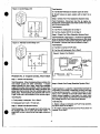
Figure 4. Control Relay CR1
Test Results:
A. Fuel Shutoff Valve(s) are closed: Open all valves
B. Shutoff valves are open, engine will not start: Go to
Step3
Step 3- Check Fuel Flow (Gasoline System Only)
Test Procedure:- Disconnect fuel nne at engine carburetor Inlet. Crank engine and check fuel flow from open
end of disconnected line.
Test Results:
A. Fuel Flow is inadequate: Go to Step 4
B. Fuel flow checks GOOD: Go to Step 6
Step 4- Check Fuel FIHer (Gasoline System Only)
00047
Rgure 5. Alternate Control Relay CR1
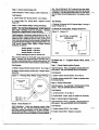
Test Procedure:- See Figure 6. If fuel flow to carburetor
Is low, try a new fuel filter. Make sure arTow on filter body
points In direction of flow toward carburetor. With new filter Installed, recheck fuel flow as outlined In Step 3.
Test Results:
A. Fuel flow Is nonnal: STOP tests
B. Fuel flow still Inadequate: Go to Step 5
Figure 6. Engine Fuel System
3
INSTALLER'S
CONNECTION
/POINT
FUEL
FILTER
14
15
..,.__ FLOW
00046
(
Problem No. 2 - Engine Cranks, Won't Start
OOO&S
Step 1 - Check Fuel Quantity
Test Procedure: When troubleshooting a problem, the
most simple causes are often overtooked. It engine
cranks nonnally but won't start, check that adequate
supply of the proper fuel Is available. Many RV generator
lnstallaUons with shared fuel tank utilize a generator fuel
pickup tube that is shorter than the vehlde engine's fuel
pickup tube. For that reason, the generator will •run out
of gas• while fuel Is still avaHable for the vehicle engine.
Test Resuns:
A. Fuel quantity Is adequate: Go to Step 2.
Step 5- Check Fuel Pump (Gasoline System Only)
Test Procedure:- Locate the 4-tab tenninal connector to
which Wires 14 connects. Locate Wire 14 from Fuel Pump
on the terminal connector. Connect the positive (+) test
lead of a d-e voltmeter to the Fuel Pump's Wire 14 terminal; connect negative (-) test lead to a clean frame
ground. Crank engine- the voltmeter should Indicate battery voltage and the Fuel Pump should operate.
Test Results:
B. Inadequate fuel In tank: All fuel tank.
A. Battery voHage is Indicated and Fuel Pump operates,
but still no start: Go to Step 6
Step 2 - Check Fuel Shutoff Valves
Test Procedure: The fuet supply line In th&' vehicle may
be equipped with one or more fuel shutoff valves. If
engine will not start. check that all fuel supply valves are
open.
B. No battery voltage Indicated and Fuel Pump does not
operate: Go to Step 7
15
Figure 7. Choke Module
Step 6· Check Engine Ignition System
Test Procedure:- Refer to section In this Manual entitled
ENGINE TROUBLESHOOTING. Also refer to the ENGINE SERVICE MANUAL, If necessary.
.f'\
Test Results:
A. Ignition System ched<s GOOD: Go to Step 7
5
4
3
<=->
""""'
<=»
2
B. lgl)ition System ched<s BAD: Repair or replace defective component(s) mas necessary
~".. _
Step 7· Test Choke Module
NOTE: The following procedure will test the Wire 1
diode, the field boost diode, and the field boost
resistor. To test these components, It Is recommended that a Volt-Ohm-Milliammeter having a
DIODE TEST capability be used. The solid state clrult that regulates automatic choke opening and
closing cannot be tested In the field. That circuit will
be tested In Ste 8 by observln choke o eratlon.
Test Procedure:- See Figure 7. Disconnect all wires from
Choke Module terminals to prevent Interaction. Then,
proceed as follows:
1. To test the Wire 14 diode, connect one VOM test lead
to Terminal 3 of the Choke Module; connect second test
lead to .Terminal 1. Observe the meter reading. Then,
reverse the test leads (reverse the d-e polarity) across
those Choke Module terminals and again observe the
reading. At one polarity, the VOM should read Infinity. At
the opposite polarity, the VOM should indicate the forward resistance of the 6 amp, 100 volts diode In the Wire
14 circuit. If using a VOM having the diode test feature,
allowable voltage drop across the diode is 0.6 to 0.8 volt.
4/REDl
00043
Step 8- Check Automatic Choke Operation
Test Procedure:- See Agure 8. Crank engine while observing choke operation. The Choke Solenoid CS should
pull in to close choke for about 0.2-0.4 seconds, should
then de-energize to open choke for about 2 seconds. This
cydic action should occur while the engine Is cranking. H
Choke Solenoid does not actuate, check for binding. Also
check for proper choke adJustment (see ADJUSTMENTS
section),.
Test Results:
A. Choke operation checks GOOD, engine still won't
start: Go to Step 9
B. Choke operation checks BAD: Try adjusting choke- If
it still does not operate, replace Choke Module
Figur8 8. Automatic Choke
O l.____
2. To test the Field Boost diode and resistor, connect one
VOM test lead to Choke Module Terminal 3, the second
test lead to Terminal 2. Note the meter reading. Then,
reverse the test leads (reverse polarity) and again observe the VOM reading. At one polarity. the meter should
Indicate infinity. At the opposite polarity, the meter should
read the forward resistance of the diode plus the resistance of the Field Boost Resistor. tf a VOM having the
diode test feature is used, allowable vonage drop will be
0.6 to 0.8 volts PLUS the voltage drop across the resistor.
NOTE: The Field Boost Resistor Is rated 47 ohms at
2 wans (plus or minus 10%). The Field Boost diode
Is rated 1 amp at 600 volts.
Step 9· Check Engine Compression/Condition
3. The Choke Module circuit Includes a metal oxide Varistor, rated 22 volts, 0.6-0.8 Joule. There Is no good method
of testing a Varistor In the field. Typically, when a Varistor fails it will overheat and melt. Inspect the Choke
Module- if evidence of overheating and melting is observed, replace the Choke Module.
Test Procedure:- Refer to section entitled ENGINE
TROUBLESHOOTING. If necessary, also refer to the ENGINE SERVICE MANUAL
Test Results:
A. Engine,Checks GOOD: Go to Step 10
Test Results:.
B. Engine checks BAD: Repair/replace engine as necessary
A. All Choke Module tests are GOOD: Go to Step 8
B. Choke Moudle tests BAD: Replace Choke Module
16
Step 10. Test Control Relay CR2
Step 2 • Check 011 Pressure SwHch
Test Procedure:- See Figure 9. Disconnect Wire 18 from
Relay Termlnal2 and Wire 85 from Termlnal4, to prevent
Interaction. Set a VOM to Its "Rx 1" scale and zero the
meter. Then, connect the VOM test leads aa-oss Relay
Tennlnals 2 and 4- the meter needle should swing upscale (con11nuity). Hold Slar1/Stop. Switch at START to
crank engine- the VOM needle should drop all the way
downscale (infinity).
Test Procedure: Set a VOM to Its "Rx1" scale and zero
the meter. Dlsco'nnect Wire 85 from the Switch terminal.
then test the Low 011 Pressure Switch (Fig. 10) as follows:
Test Results:
A. Control Relay CR2 checks GOOD: Repeat Steps 1
through 9
B. Control Relay CR2 checks BAD: Replace Relay CR2
1. Connect one VOM test lead to the switch terminal, the
remaining test lead to a clean frame ground. Meter
should Indicate continuity.
2. Crank engine. The VOM needle should drop all the
way downscale (infinity) as oil pressure lnaeases.
3. If the engine starts and runs. hold terminal end of Wire
85 Into firm contact with a dean frame ground. Engine
should shut down.
Test Results:
Figure 9. Control Relay CR2
A. Oil Pressure Switch checks GOOD: Go to Step 3.
.B. 011 Pressure Switch checks BAD: Replace switch.
17
17
18
5
OIL
00042
Problem No.3- Engine Cranks and Starts,
Shuts Down When Start/Stop Switch Is
Released
Step 1- Check Engine 011 Level
Test Procedure:- Check engine oil level as outlined in
Owner's Manual. H olllevells low, suffident oil pressure
to open the Low Oil Pressure Switch contacts will not be
developed. With Start/Stop Switch at START, Control
Relay CR2 action will open the engine ignition drcult to
ground. However. as soon as the Start/Stop Switch Is
released, CR2 contacts will close and closure of the Low
011 Pressure Switch contacts will close the Ignition circuit
to ground and ignition will tennlnate. The result will be an
engine- shutdown as soon as the Start/Stop Switch is
released.
Test Resuns:-
A. Oil level Is LOW: Add oil as required (don't forget 011
Makeup Tank).
Step 3- Check Oil Temperature Switch
Test Procedure: Set a VOM to Its •Rx1• scale and zero
the meter. Disconnect Wire 85 from the Switch tenn!nal.
then test the Oil Temperature Switch (Fig. 10) as follows:
1. Connect one VOM test lead to the switch tennlnal. the
remaining test lead to a clean frame ground. Meter
should Indicate continuity.
2. Hthe engine starts and runs, hold terminal end of Wire
85 Into firm contact with a dean frame ground. Engine
should shut down.
Test Results:
A. air Temperature Switch contacts check GOOD: Go to
Step 4.
B. Oil Temperature Switch contacts check BAD: Check
wiring.
B. Oil level Is GOOD: Go to Step 2
NOTE: You may wish to check engine oil pressure
See ENGINE SERVICE MANUAL for oil pressur
check rocedures and s clflcatlons. .
17
Step 4 - Check Control Relay CR1
Test Procedure: Refer to Step 6 under Problem No. 1.
Test Results:
tion. Set a VOM to Its •Rx1" scale and zero the meter.
Connect the first meter test probe to-the Wire 55 tennlnal
of Resistor. Connect second test probe to a dean frame
ground. Meter should Indicate about 1 ohm (plus or mtnus
5%).
r'\
A. Control Relay CR1 checks GOOD: Go to Step 5.
B. Control Relay CR1 checks BAD:
Relay CR1.
Replace Control
Test Results:
A. Resistor R1 checks GOOD: Repeat Steps 1 through 4
under Problem No. 3.
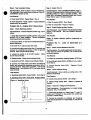
Step 5- Check Stator Battery Charge Windings
NOTE: The Volt-Ohm-Milliammeter (YOM) used t
est Stator windings must be accurate. Recom
ended Is a dl Ita I meter of hi h accurac .
B. Resistor R1 checks BAD: Replace Resistor R1.
Figure 12. Resistor R 1
Test Procedure: Disconnect Wires 66 and 77 (Fig. 11)
from the Battery Charge Rectifier BCR terminals. Set a
VOM to Its "Rx1" scale and zero the meter. Connect the
meter test leads across the tenninal ends of Wires 66 and
77, just removed from Battery Charge Rectifier BCR. The
VOM should indicate Stator Battery Charge Winding
resistance, as follows:
Series NP45G
T
BATTERY CHARGE
WINDING
55
R1
66
jil
.
1.·; U
= 0.12 ohm
series NPSSG = 0.09 ohm
=
1
0
Series NP65G 0.07 ohm
All lest readings are plus or minus 10%.
00053
rh GROUND
Now, set the VOM to its "Rx10,000" scale and zero the
meter. Connect one VOM test lead to terminal end of
Wire 66, remaining test lead to a clean frame ground. No
upscale movement ofthe meter should be noted (Infinity).
Problem No. 4 - Engine Starts Hard, Runs ( \
Rough
Test Resuns:
Step 1- Check Engine Ignition System
A. Battery Charge Winding checks GOOD: Go to Step 6
Test Procedure: Refer to ENGINE TROUBLESHOOTING section. Also see ENGINE SERVICE MANUAL
B. Battery ~harge Winding checks BAD: Replace Stator
Assembly.
Test Results:
A. Ignition system checks GOOD: Go to Step 2.
Figure 11. Checking Stator Bartel)' Charge Windings
r
n
M
~-~-~J
~
I.
B. Ignition system checks BAD: Repair or replace defective component(s).
r 1o
BATTERY CHARGE
WINDING
AI
Step 2 • Check Carburetlon
I
Test Procedure: See ENGINE TROUBLESHOOTING
section. Also see ENGINE SERVICE MANUAL
0
ri-.OAOIHI
Test Results:
A. Checks GOOD: Go to Step 3.
~66
~n
B.
Step 3 - Check Engine Compression
00051
Test Procedure: Refer to ENGINE TROUBLESHOOTING section. Also see ENGINE SERVICE MANUAL
Step 6- Check Resistor R1
Test Results:
Test Procedure: Inside the generator panel, locate
Resistor R1 (Fig. 12). Test wire 0 (between Resistor R1
and frame ground connection) for an open oonditlon.
Correct open condition, if necessary, before proceeding.
Dlsconned Wire 55 form the Resistor to prevent interac-
A. Engine checks GOOD: Go to Step 4.
B. Engine checks BAD: Repair as required.
18
\
Ch~ BAD: Adjust, repair or replace as necessary.
Step 4 - Test Automatic Choke
Step 2 • Check Wire 18
Test Procedure: Refer to Steps 7 and 8 of Problem No.
2 for automatic choke system test procedures. See ADTest Results:
Test Procedure: Refer to WIRING DIAGRAM. Page 11.
Test Wire 18 between Ignition Shutdown Module ISO and
Start/Stop Switch for open or shorted condition. Also
check Wire 18 between Start/Stop Switch and Control
Relay CR2 for open or shorted condition.
A. Choke tests GOOD: Repeat Steps 1 thru 3.
Test Results:
B. Choke tests BAD: Repair, adjust or replace defective
component(s) as necessary.
A. Wire 18 checks GOOD: Go to Step 3.
JUSTMENTS section as well.
Problem No.5- Engine Won't Shut Down
Step 1 • Check Start/Stop Switch.
Test Procedure: Test the Start/Stop Switch (Fig. 13) as
follows:
1. Check Wire 0 (between Start/Stop Switch and ground
·tennlnal GT) for open condition. Ground connection
must be good before proceeding.
2. Dlsconned Wires 17 and 18 from Switch terminals, to
prevent fnteractton.
3. Set VOM "Rx1" scale and zero the meter.
4. connect one meter probe to the Wire 17 termtnal, and
~nect the remaining test probe to Wire 0 (ground)
tennlnal. Meter should Indicate Infinity.
5. Actuate the Switch to Its START position.
should read contlnutlty.
Meter
B. Wire 18 checks BAD: Repair or replace.
Step 3 - Check Engine Ignition System
Test Procedure: See ENGINE TROUBLESHOOTING
section In this Manual. Also see ENGINE SERVICE
MANUAL
Test Results:
Repair or replace defective ignition components as
necessary.
Problem No. 6 - Loss of Generator a-c
Output
Step 1 .. Check Clrcuh Breakers CB1/CB2
Test Procedure: Try resetting applicable circuit breaker.
If this does not correct the problem, use a VOM to test
the circuit breakers.
Test Results:
6. Release Switch. Meter should Indicate Infinity.
A. Problem ts corrected by resetting Breaker. STOP test.
7. Set Switch to STOP. Meter shoukllndicate infinity.
B. Circuit Breaker tests GOOD. stUIIittle or no a-c output:
Go to Step 2.
8. Connect one meter probe to the Wire 18 tennlnal of
Switch. and connect the remaining test probe to Wire 0
(ground) terminal. With Switch at START, VOM should
Indicate Infinity. Hold Switch at STOP and meter should
read continuity.
A. Start/Stop Switch SW1 checks GOOD: Go to Step 2.
B. Start/Sto Switch SW1 checks BAD: Re lace Switch.
ra.
Replace Circuit
Step 2 - Check Vehicle Wiring
Test Procedure: Check vehicle a-c wiring and a-c distribution components.
Test Results:
Figure
C. Circuit Breaker tests BAD:
Breaker(s).
Start/Stop Switch
1 1.1
17
Test Results:
A. Vehicle wiring checks GOOD: Go to Step 3
B. Vehicle wlrtng checks BAD:
needed.
Repair or replace as
Step 3 - Check a-c Voltage and Frequency
Test Procedures: Check generator a-c output voltage
frequency (Fig. 14) as follows:
1. Disconnect generator a-c output leads T1 (red), T2
{white) and T3 (black) In the junction box where they
connect to vehide wiring.
2. Connect an accurate a-c voltmeter and frequency
meter across generator a-c output leads T1 (red) and T2
(white).
~---18-----------
18
I
19
3. Start the generator engine, let It stabilize and warm up
at NO-LOAD.
Flgurs 14. Test Points for a-c Voltage/Frequency
time. This total should be less than the generator's rated
wattage/amperage capacity. Reduce electrical loading
as necessary.
B. A ground fault condition may exist In the generator or ( \ ,
on one or more connected electrical loads. This can
increase current flow dramatically and may cause circuit
breakers to trip. See INSULATION RESISTANCE
TESTS on Page 9.
C. Loss of engine power may have occurred. Check
engine for adequate air flow, dogged air cleaner, lncorrect lgnHion timing, mechanical failure. Incorrectly adjusted carburetor, etc. Complete repairs to engine as
necessary.
Step 5- Check/AdJust Engine Governor
4. Read the no-load a-c voltage and frequency. Indicated
readings should be 124 volts at 62 Hz.
Test Results:
A. Voltage and Frequency check GOOD: Go to Step 4.
B. Voltage and Frequency are both high or low: Go to
StepS.
Test Procedure: If the no-load voltage and frequency
are both correspondingly high or low, ad}usbnent of the
engine govemor may be required. See ADJUSTMENTS
section. Following govemor adjustment to the correct a-c
frequency, the a-c voltage must be checked. H engine
speed (frequency) Is correct but a-c voltage Is not, adjustment of the Electronic Voltage Regulator may be required.
Test Results:
A. Voltage and Frequency are correct: STOP tests.
C. Low or no a-c voltage: Go to Step 6.
B. Voltage/Frequency still Incorrect. Go to Step 6.
D. Frequency GOOD, Volts HIGH: Go to Step 10.
Step 6 • Check Field Boost Circuit
Step 4 - Check Load Voltage and Frequency
OTE: Some "residual" magnetism Is normall
resent In the Rotor (revolving field). This residual
agnetlsm should be adequate to create the neces
ry "pickup" voltage In the Stator windings. Fo ·
hat reason, failure of the Field Boost function will
not usually cause a problem unless the Rotor'
residual ma netlsm Is also lost.
Test Procedure: Proceed as follows:
1. Check that load leads are properly connected to a-c
output terminals T1 (red), T2 (white) and T3 (black).
Test Procedure: Test the Field Boost circuit as follows
(Agure 15):
2. connect an accurate a-c voltmeter and frequency
meter to a-c output leads. Connect meters across leads
T1 (red) and T2 (white).
1. Disconnect Wires 4 from Pin 2 of the Choke Module
CM ·
.--------------------,
/\
'
I
Figure 15. Choke Module
3. Start the generator engine, let It stabilize and wann up.
Then, tum ON electrical loads by whatever means
provided (such as double throw switch or circuit breaker).
Apply loads as close as possible to the unlfs rated
maximum continuous wattage/amperage capacity.
5
4. With rated loads applied, check the a-c voltage and
frequency readings. Voltage should be at least 116 volts;
frequency should be at least 58 Hz (or hlgher).Test
Resuhs: If voltage and frequency are good at no-load
but drop excessively when electrical loads are applied,
check the followfng.
-
•
J
c::D
<CD
1
..,..
d-J.J ~ '-.
-4CREDl- 0 0 0 4 3
~------------------------~~
A. Generator may be overloaded. Add up the wattage or
amperage of an electrical loads being operated at one
20
-
-
-
2. Connect the positive(+) test lead of the a d-e voltmeter
•
to Pin 2 of Choke Module CM. Connect negative(-) test
lead to a clean frame ground .
3. Crank the engine. The voltmeter should indicate about
7-1 0 c;,olts d-e wtth engine cranking.
Test Results:
-
~
Test Procedure: Disconnect Stator Excitation Winding
output leads 2 and 6 (Fig. 17) from the Electronic Voltage
Regulator. Set a VOM to Its ·Rxt" scale and zero the
meter. Connect VOM test leads across terminal ends of
Wires 2 and 6. The VOM needle should swing upscale
and indicate the following resistance:
NP45G Units = 2.2 ohms
NP55G Units= 1.8 ohms
NP65G Units = 1.6 ohms
*All resistance values are plus or minus 10%.
B. Engine cranks but no d-e voltage is indicated: Replace
Choke Module CM and recheck for proper voltage. If
voltage is good, STOP test
4. Gain access to Brushes and Slip Rings (Fig. 16).
- - - - - - - - -- - - - - --
Step 7 - Check Stator Excitation Windings
A. Engine won't crank: Go to Problem No. 1.
C. Engine cranks and normal voltage is indicated: Continue test.
-
Now, set the VOM to its "Rx1 0,000" scale and again zero
the meter. Connect one VOM test lead to W ire 2, and the
remaining test lead to a dean frame ground. You should
not detect any upscale movement (Infinity) of the VOM
needle.
Figura 17. Stator Excftation Winding Test Points
5. Connect the positive lead of a d-e voltmeter to the
terminal of the positive(+) brush (RED lead connection).
Connect voltmeter test lead to a clean frame ground.
0 0 0 0 0 0
6. Crank engine. The voltmeter should indicate about
7-10 volts d-e with engine cranking.
ELECTRONIC
VOLTAGE
0
REGULATOR
•
00055
Test Results:
A. Excitation wlndings check GOOD: Go to Step 8.
B. Excitation windings check BAD: Replace Stator Assembly.
Test Results:
NOTE: Also see INSULATION RESISTANCE TESTS
lon Page 9. Typically, In the above test, a low reslsance Indicates a shoned condition; a high resls·
ance Indicates an open condition.
A. Engine won't crank: Go to Problem No. 1
B. Engine cranks and no d-e voltage indicated, but voltage was Indicated In Item 3 of test: Repair or replace
Wire 4 between Choke Module CM and the positive(+)
brush.
Test 8 - Check Stator a-c Power Warnings
Test Procedure:. Test the Stator (Flg. 18) a-c power
windings as follows:
C. Engine cranks and normal voltage Indicated: Go to
Step 7.
1. Disconnect a-c power winding output leads 11 and 22
from tht'l Electronic Voltage Regulator.
2. Disconnect a-c power winding output lead 33 from
Circuit Breaker CB 1.
•
3. At the wire nut junction of a-c output leads 22 and 44,
separate the two wires.
21
4. Set a VOM to Its •Ax 1n scale and zero the meter.
Connect VOM test leads across wire ends of Wires 11
and 22 and note the resistance reading, In ohms. Resistance should be as follows (plus or minus 10o/o):
NP45G Units = 0.4 ohms
NP55G Units = 0.3 ohms
NP65G Units= 0.2 ohms
5. Connect VOM test leads aa-oss wire ends of Wtres 33
and 44. Again, note the resistance. Resistance should
be the same as fn Item 4 above.
6. Set VOM to its "Rx1o,ooo· scale and zero the meter.
COMect one VOM test lead to Wire 11 and the second
test lead to frame ground. The VOM needle. should not
move upscale (Infinity). Now, connect one test lead to
Wire 33 and the second lead to frame ground. Meter
should Indicate infinity.
2.
Set a VOM to Its "Rx1 : scale and zero the meter.
Connect VOM positive(+) test lead to the positive(+) Sllp
Ring (nearest the Rotor bearing). Connect negative(-) ( \
VOM test lead to the negative (-) SOp Ring. Meter should
Indicate the following resistance (plus or minus 10%) at
20°C {68°F).
NP45G Units =13.9 ohms
NP55G Units = 15.5 ohms
NP65G Units = 11.1 ohms
3. Reassemble Brushes and Brush Holder, retain Brush
Holder: and Wires. Make sure Brushes are property
seated In Brush Holder and are contacting the Slip Rings
properly. Rotate Rotor several times to seat Brushes
against Slip Rings.
Test Results:
A. Rotor circuH checks GOOD: Go to Step 10.
Test Results:
B. Rotor circuit tests BAD: Repair or replace defective
wtre(s) or brushes. Replace defective Rotor Assembly.
A. Power Windings check GOOD: Go to Step 9.
Step 10 ·Check Voltage Regulator Sensing
B. Power Windings check BAD: Replace Stator Assembly.
OTE: Sensing signals to the Electronic Voltag
egulator are delivered via Wires 11 and 22. Loss o
hese sensing signals to the Regulator due to an
pen or shorted condition (In a non-compensated
Regulator) nonnally means a "Full Field" condition
nd resultant high a-c voltage output. Howeve~, th
P series generators are equipped wHh a vonag ~
egulator that provides automatic protection
l
galnst an open sensing circuit and the resultant
high voltage condition. Should sensing wires 11 o
2 open, Voltage Regulator action wlllautomatlcall
pen the Excitation circuit to the Rotor and a-c .
utput voltage will drop dramatically. Total a-c volt· ·
ge output from the Stator a-c power windings will
a .result of residual Rotor ma netlsrn on I .
Figure 18. Stator a-c Power Windings Test Points
Test Procedure: Recheck Wires 11 and 22, between the
Electronic VoHage Regulator and the Stator, as outlined
InStep 8.
Test Results:
A. Wires 11 and/or 22 Indicate open or shorted condition:
Repair or replace wires as necessary.
Step 9 • Ctleck Rotor (F.Ield} Circuit
B. Wires 11 and 22 check GOOD: Go to Step 11.
Test Procedure: Use a VOM to test Wire 4, between
Electronic Voltage Regulator and Choke Module for open
or shorted condltlon. Wire 4 between Choke Module and
Brushes was previously tested In Step 6. Then, inspect
brushes and slip rings and test Rotor as tallows:
1. Remove Wires 4 and o from Brushes, then remove
Brush Holder. Inspect Brushes and Brush Holder.
Replace H cracked, damaged, wom excessively, etc.
Inspect Slip Rings. If they are dull or .tamlshed, polish
wHh fine sandpaper. DO NOT USE ANY METALLIC
GRIT TO CLEAN SUP RINGS. Use low pressure air (25
psi or less) to blow away cleaning residue.
Step 11· Check/ Adjust Voltage Regulator
Test Procedure: Refer to ADJUSTMENTS section.
With correct a-c frequency Indicated, try adjusting the
Voltage Regulator. Frequency and voltage must both be
within the specified limits.
Test Results:
A. Frequency GOOD, cannot adjust In the correct voltage: Replace the Voltage Regulator, adjust and test unit.
B. Frequency and Voltage both GOOD: STOP tests.
22
f\
ENGINE TROUBLESHOOTING
General
Check Carburetion
Most problems pertinent to engine operation may be dassmed as one (or a combination) of the following:
1. Will not start
2. Hard Starting
3. Lack of power
4. VIbration
5. Overheating
6. High oil consumption
See TROUBLESHOOTING GUIDELINES. Before
making a carburetlon check, make sure (a) an adequate
supply of fuel Is available, (b) all fuel shutoff valve(s) are
open. and (c) fuel flow Is adequate. Try adjusting the engine carburetor. Check automatic choke operation and
make sure the choke is adjusted proper1y. If engine will
not start, remove and Inspect the Spark Plug.
If Spark Plug Is WET. look for:
1. Overchoklng
2. Excessively rich fuel mixture
3. Water in fuel
4. Intake valve stuck open
When the cause of a problem Is not readily apparent, perform a check of the engine's Compression, Ignition and
Carburetlon systems. Checkout of these systems, if performed In a systematic manner, can usually be done In a
few minutes. It Is the fastest and surest method of finding
the cause of a problem.
If Spark Plug Is DRY, look for:
1.Leaking carburetor gasket(s)
2. Dirty or gummy cartiuretor
3. Intake valve stuck dosed
4. Inoperative fuel pump
What appears to be an engine problem may sometimes
be caused by the system that the engine Is driving. For
example. overloading the generator (exceeding Its wattage capacity) can cause the same Indications as an underpowered engine. A shorted condition In the generator
or rn electrical loads connected to the generator can also
appear to be an underpowered engine.
Checking Engine Compression
For instructions and lnfonnation on checking engine compression, refer to the ENGINE SERVICE MANUAL H
compression is poor, look for:
1. Loose spark plug(s)
2. Loose cyDnder head bolts
3. Blown head gasket(s)
4. Bumed valves or valve seats
5. Insufficient valve tap~t clearance
6. Warped cylinder head(s)
7. Warped valve stems
8. Wom cylinder bore and/or rings
9. Broke connecting rod(s)
A simple check to determine H fuel is reaching the combustion chamber Is to remove the spark plugs and pour
a small amount of gasoline through the Spark Plug hole.
Install and tighten Spark Plugs. Crank engine. If engine
fires a few times and then stops. look tor the same conditions as a dry plug.
Check Engine Ignition
Other Problems that Might Affect Engine
Operation
1. Hard Starting or Will Not Start
a Loose drive belts or pulleys- these can cause a
"backlash• effect that will counteract engine cranking
effort.
b. Starting under load- anemptlng to start with heavy
electrical loads applied can often cause problems.
c. Shorted condition In the generator or in connected
electrical loads can impose a heavy load on the engine, thus preventing start.
2. Vibration
Checkout and servldng of the engine Ignition system is
discussed In detail, In the ENGINE SERVICE MANUAL
To check Ignition system operation, connect a SPARK
TESTER to the end of a the Spark Plug wires. Then, crank
the engine with both spark plugs removed. If a hot blue
spark Jumps the Spark Tester gap, you may assume the
Ignition System Is working properly. If spark jumps the
Tester gap, you may wish to try new spark plugs. Hspark
does NOT jump the Tester gap, look for:
1. 'Defective gnltion Module(s) IM1 and 1M2
2. Defective fgnttlon Shutdown Module ISO
3. Defective Control Relay CR2
a. Check for defective or damaged pulleys, drive
belts, or Rotor.
b. Check for loose mounting bolts and tighten.
3. Power Loss ·
a. Check for binding or drag In drtve train (pulleys
and belts}
b. Check for defective Rotor bearing.
c. Check for Rotor contact with Stator windings.
d. Check for excessive drive belt tension.
4. Noise
a. Check for a damaged Rotor and/or Stator
b. Check for loose or damaged pulleys and drive
belts.
NOTE: If engine runs but misses during operations
check to see If Ignition System Is at fault by connectIng the Spark Tester between the high tension Spark
Plug wire and the Spark Plugs. A spark miss will be
readily apparent.
23
ADJUSTMENTS
6. Check a-c frequency; it should be 61-63 Hz. If not. tum
ADJUSTER NUT until frequency is correct.
General
This section is included with other a-c generator Information, because the covered information is so Important to
proper generator operation and correct a-c output. The
engine governor adjustment may belong in the ENGINE
SERVICE MANUAL However, that adjustment is so
Important to correc.1 a-c output frequency and voltage that
it is Included here.
7. With governed speed at 61-63 Hz (no-load), check
voltage reading. Voltage should be 122-126 volts. If not,
adjustment of the Voltage Regulator is required.
A
Adjustments included In this section Include the foDowtng:
IDLE STOP SCREW
~
CARBURETOR
1 ,
THROTTLE LEVER
1. Engine governor adjustment
2. Voltage Regulator adjustment
3. Automatic Choke adjustment ..
NOTE: An optional LP gas (propane) fuel system 1
vallable for use with the NP series generators.
nstructlons for the Installation and adjustment o
he LP as conversion kit are Included whh the kit.
ANTI-LASH
SPRING
Engine Governor Adjustment
A
Also see ROTOR ROTATIONAL SPEED on Page 4
of this Manual. The engine governor Is generally adjusted to deliver a generator a-c output frequency of
61-62Hz, with no electrical loads connected to the gen. erator. Following the no-load adjustment of engine
.speed, unit operation should be checked with a load
applied. Adjust the engine governor as follows:
1. Visually inspect ANTI-LASH SPRING, make sure it is
not broken or disengaged. Spring ends must be hooked
Into GOVERNOR LEVER at bottom end and into carburetor THROTTLE LEVER at top.
Voltage Regulator Adjustment
AUTION: DO NOT adjust the Voltage Regulato
ntll ~c output frequency Is correct. See ENGINE
GOVERNOR ADJUSTMENT.
2. Loosen GOVERNOR CLAMP NUT.
3. Push spring end of GOVERNOR LEVER all the way
up, to wide open throttle position. While holding the
B Check that a-c frequency is correct, as outlined in
ENGINE GOVERNOR ADJUSTMENT. If frequency is
within stated limit (61-63Hz), a-c voltage output should
be 122-126 volts. If voltage Is not ~rrect, adjust the
Voltage Regulator by turning the VOLTAGE ADJUST
potentiometer slowly until a-c voltage Is within the stated
limits. Voltage regulator Is mounted In the generator
con rol.
I ertor.
.
LEVER down, Insert a screwdriver into slotted end of
GOVERNOR SHAFT and rotate SHAFT fully
counterclockwise. Then, tighten the GOVERNOR
CLAMP NUT to 100 inch-pounds of torque.
AUTIONI: Governor shaft MUST be rotated full
ounterclockwlse with throttle wide open or lull
overnor travel will not be reached. Governor clamp
nut must be tight or full governor travel may be lost
ue to vibration.
B
4. Connect an accurate a-c frequency meter and
voltmeter across generator a-c output leads T2 (white)
and T3 (black) for Series NP45GJNP55G; or across leads
T1 (red) and T2 (white) for Series NP65G. See Step 3
under Problem No.6 on Page 19. (Check A-C VOLTAGE
AND FREQUENCY).
0 Q 0 [) 0 0
ELECTRONIC
VOLTAGE
REGULATOR
5. Start the engine. Let it stabilize and warm up for a few
minutes with NO ELECTRICAL LOADS APPLIED TO
GENERA=TOR.
24
-
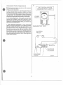
c
Automatic Choke Adjustment
•
AIR CLEANER SHOWN
REMOVED FOR CLARITY
C
Check automatic choke operation and (If necessary)
adjust the choke as follows:a. Check Choke Operation:- Crank the engine while observing automatic choke operation. Initially, the Choke
Solenoid should energize to dose choke for about 0.2 to
0.4 seconds and then d&-energlze for about 2 seconds to
open the choke. This open/close cycle should repeat Itself until the engine starts and cranking is terminated.
CHOKE
PLATE
b. Pre-Choke Adjustment:- With engine cold and Choke
Solenoid NOT actuated, check that carburetor choke
plate Is about 1/Sinch away from its full open position. If
necessary to obtain the desired setting, use noodle nose
pliers to bend tip of BI-METAL.
D
c. Choke Solenoid Adjustment:- Loosen screws that
retain the CHOKE SOLENOID to Its retaining bracket.
Slide the CHOKE SOLENOID In the slotted holes to ad·
just axial movement of the SOLENOID plunger. Adjust
the axial movement so that, with the carburetor choke
plate closed, the CHOKE SOLENOID plunger Is just bottomed in the solenoid coli (plunger at full actuated position). With choke plate closed and plunger bottomed In
the coli, tighten the two screws. Then, crank engine and
check choke operation .
CARBURETO
SLOTIED
HOLES
•
SOLENOID
PLUNGER
SOLENOID
CHOKE
•
25
00068
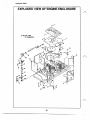
Drawing No. 75464
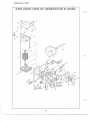
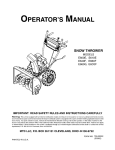
EXPLODED VIEW OF E.NGINE ENCLOSURE
*
SEE EXP. VIEW
OF CARBURATOR
7
26
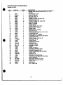
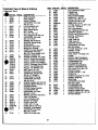
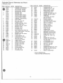
Exploded View of Sheet Metal
e
Drawing No. 75464
ITEM
PART NO.
1
1
2
3
4
5
67877
67198-N
67890
74915
6
63036
7
8
9
74904
56892
70520
74903
74916
74908
73190
73189
73188
74902
43146
22097
73191
48571
22129
75246
11-74260
74900
73186
23484-D
22717-B
22717-A
67886
74955
74965
22447
40936
48031-E
47662-BB
74956
42907
46509
08-74260
09-74260
48031-D
29289
73132
10
11
12
13
. 14
15
16
17
18
19
20
21
22
23
24
25
26
27
28
29
30
31
32
33
34
35
36
37
38
39
40
41
42
43
REQ'D
·1
1
1
1
6
1
22
1
1
1
8
1
1
1
2
4
4
1
2
2
4
1
1
1
1
1
2
1
1
1
1
1
1
1
1
1
1
1
1
2
2
2
DESCRIPTION
ENGINE ASS¥ (See EXPLODED VIEW OF V-TWIN
ENGINE)
KEY, Woodruff- 6 x 25
WASHER, Belleville
NUT, Hex- M2o-1.50
SCREEN, Air Inlet
SCREW (Crlmptlte)- No. 8-32 x 114•
HOUSING, Engine Top
SCREW (Crlmptite )- No. 1G-32 x 319•
MODULE, Shorting
SCROLL, Flywheel
COVER, Base #2
SCREW {Taptlte)- MS x 1Omm
WRAPPER- No. 2 CyUnder
COVER, Valley
WRAPPER- No. 1 Cyllndert
WRAPPER, Barrel
CAPSCREW, Hex Head- M6·1.00 x 10mm
LOCKWASHER- M6
COVER,~-No.1~
CAPSCREW, Hex Head- MB-1.25 x 1Omm
LOCKWASHEA- M8
SCREW (Taptlte)- 3/8.·16 x 114•
WIRE ASSY- No. 16
COVER, Starter
WRAPPER, Crankcase
BUSHING, Snap
GROMMET, Rubber
GROMMET, Rubber
0-RING
PROBE, Oil Makeup
RETAINER, Oil Makeup Probe
WASHER (Shakeproof)- M6
SCREW, Socket Head- M6-1.00 x 8mm
CLAMP, Hose
HOSE· 5/1 10
BRACKET, 011 Makeup Pump
CAPSCREW, Hex Head- M8·1.25 x 16mm
PUMP, 011 Makeup
WIRE ASSY (Ground)· 5.5• long
WIRE ASSY (Ground)- 15•1ong
CLAMP, Hose
TAPE. Foam
BOOT, Spark Plug
a-
Z1
'
.
.
. ·
Drawing No. 75218
EXPLODED VIEW OF BASE & PULLEY
(\
28
...
---·----
---··-----
?
ITEM PART NO. AEQ'D
Exploded View of Base & Pulleys
44
·orawfng No. 75218
45
AARTNO. REQ'D
1
2
3
4
72372
72382
38353
25017
5
6
7
8
9
10
11
22237
22241
72391
73147
45n1
52858
51730
1
1
4
4
12
4
2
2
2
8
2
12
13
14
15
16
17
18
29459
75215
73146
75209
73174
67897
55173
2
2
4
2
1
1
4
19
20
21
72383
56892
75224-A
2
32
1
1
1
1
1
1
1
'75224-8
25
75224-C
73106-A
73106-B
73106-C
75216
49451
42633
26
27
72381
73118
1
1
28
74906
74908
72375
73185
22097
74909
12
9
1
75242
74910
73156
49099
48031-E
47662-U
47662-BG
50190
74913
4
1
1
1
4
1
1
5
1
73181
1
23
24
29
30
31
32
33
34
35
36
37
38
39
40
43
5
1
1
1
1
46
DESCRIPTION
BASE, Mounting
PAN, Collector
MOUNT (Rubber)
CAPSCREW, Hex Head
3/8··16 )( 112.
LOCKWASHER- M10
NUT, Hex - 319•-16
SKID, Rubber Mount
BOLT Safety
NUT, Hex- MS-1.25
NUT, Flanged Lock- MB-1.25
CAPSCREW, Hex Head
MB-1.25 x 60mm
SPRING, BettTensloner
WASHER, Spring Center
SLIDE (Nylon)
SUPPORT, Nylon SOde
MANIFOLD, Exhaust
GASKET, Exhaust ManHold
CAPSCREW, Hex Head
M8-1.25 x 20mm (Grade 10.9)
GASKET, Collector Pan
SCREW (Crlmptlte)- No. 1D-24
PULLEY, Engine Fan (NP45G)
PULLEY, Engtne Fan (NP55G)
PULLEY, Engine Fan (NP65G) .
PULLEY, Generator Fan (NP45G)
PULLEY, Fan (NP55G Only)
PULLEY, Fan (NP65G Only)
BELT (Poly V 4L)- 40•
WASHER, Pulley Retainer
CAPSCREW, Socket Head
318.·24 X 1• (Grade 5)
GUIDE, Blower Housing
CAPSCREW, Hex Head
318•-24 X 2-112•
·SCREW (Taptfte)- M6-1.00 x 20 .
SCREW (Tapttte)- M5-0.80 x 10
HOUSING, Blower
SPACER, Blower Housing
LOCKWASHEA- M6
CAPSCREw, Hex Head
M5-0.80 X 70mm
SPRING, Generator Set Mount
TANK, 011 Makeup
CAP, 011 Makeup Tank
ELBOW- 90" Barbed
CLAMP, Hose- 318.
HOSE- 3/8• x
long
HOSE- 319• 10 x 25• long
WASHER, Tank Retainer
CAPSCREW, Hex Head
M6-1.00 x 110mm
TUBE, 011 Fill and Drain
I
s·
29
47
48
49
50
51
52
53
54
55
56
57
58
59
60
61
62
63
64
65
66
67
68
69
70
71
72
73
74
75
76
77
78
79
80
81
82
83
84
85
86
87
88
74958
67871
67866
73135
73138
74936
43790
47662-BC
35461
69811
65852
52857
73179
70185
60108
74948
74950
74951
73134
38750
1
1
1
1
1
1
1
1
1
1
1
1
1
1
1
3
1
1
74949
69547
46453
29289
35472
75281
43181
43182
22473
75237
61274
75474
73176
74907
75226
56892
75229
7522.7
43118
1
1
1
22473
22097
72384-B
74908
74906
76267
1
3
1
1
2
2
1
4
1
1
1
1
1
4
1
1
4
4
4
1
3
1
2
DESCRIPTION.
CAP & DIPSTICK ASSV
Q-RINO, Cap
D-RING, Drain
PIPE, 011 Drain Adapter
ELBOW, 90' - 319• NPT
NIPPLE- 318• NPT x 2-1/4•
ELBOW- 318• NPT x 319•
HOSE- 319• x 10-112•
FmiNG, Barbed- 1/4• NPT x 318'
CAP, Hex - 114• NPT
CLIP, Hose Retainer
NUT, Ranged Lock- M6-1.00
SUPPORT, 011 Filter
FILTER, 011 (FRAM IIPH3614)
SWITCH, OU Pressure
FmiNO- 5/16•
TUBE, Outer 011
TUBE, Inner 011
ADAPTER, 011 Pad
CAPSCREW, Hex Head
M6-1.00 x 30_mm
FITTING, Barbed 90" - 5/16•
GASKET, oil Pad
LUG, Grounding
TAPE, Fo~ 1/16• thick x 8 ft.
CLAMP
SWITCH, High Temperature
SCREW, Pan Head- M3-0.50
LOCKWASHER- M3
FLATWASHER- M6
WASHER, Sprtng Retainer
SWITCH, High Water Temp.
CAP' Vynyl- 170 X 42L X 2H
ELBOW, Exhaust
CLAMP, Exhaust- 1-1/e•
COVER, Air
SCREW (Crlmptlte)· No. 1D-32
GASKET, SlkJe Pan
SLIDE PAN
CAPSCREW, Hex Head
M6-1.00 X 12nvn
FLATWASHEA· M6
LOCKWASHER-MB
COVER, Exhaust Outlet
SCREW (Taptlte)- MS x 10nvn
SCREW (Taptlte)- M6-1.00 x 20
SPACER (Plastic)
·Drawing No. 75231
EXPLODED VIEW OF GENERATOR & PANEL
f .
)2
II
66
30
--~xploded
-----
View of Alternator and Panel
Drswfng No. 75231
ITEM PART NO.
•
REO'D
1
1
1
1
1
1
1
1
1
1
4
4
1
2
1
1
4
4
1
4
22
72376
73160
73161
73162
31971
73159
73164
73165
73166
72379
73145
45n1
66386
66849
75203
74908
75214
2n56
74905
52858
29451
75201
74906
74939
22097
43116
25
26
27
28
29
30
31
32
56739
74260..10
53407
74911
48031-D
75213
71908
22473
49813
75202
1
1
2
1
4
1
3
4
5
6
7
8
9
10
11
12
13
14
15
16
17
18
19
20
21
•
1
4
1
11
4
4
4
7
1
DESCRIPTION
ITEM PART NO. REQ'D
33
34
CARRIER, lower Bear1ng
ROTOR ASSY- NP45G
ROTOR ASSY· NP55G
ROTOR ASSY- NP65G
BEARING, Ball
BEARING, Ball
STATOR ASSY· NP45G
STATOR ASSY- NP55G
STATOR ASSY- NP65G
CARRIER, Upper Bear1ng
STUD, Stator
NUT, Hex- M8-1.25
HOLDER, Brush
SCREW- M5-0.80 x 15mm
ClAMP, Stator Wire
SCREW- M5-0.80 x 10mm
SPACER, Cover
WASHER- Nylon
HOUSING, Top
NUT, Aanged Lock- MB-1.25
TAPE, Foam Rubber· 3 feet long
BRACKET, Panel
SCREW- M6-1.00 x 20mm
PUMP, Fuel ·
LOCKWASHER· M6
CAPSCREW, Hex Head
M6-1.00 x 12mm
CONTACTOR, Starter
CABLE, Starter
CABLE, Panel Ground
ELBOW, Pump Inlet
CLAMP, Hose- 5/16"
FILTEA, Fuel
MOUNT, Rubber
FLATWASHER- M6
NUT, Hex- M6
HOUSING, Panel
35
36
37
38
39
40
41
42
43
44
45
46
47
48
49
34616
39271
73601
74074
22264
51787
75235
75234
74095
1
1
1
1
5
5
2
1
,
7521Q-A
49226
65795
75205
75204
75200
75208
32300
22676
53650
75244
75471
75470
47662-AW
73513
57345
63036
33136
1
2
1
1
1
1
1
1
1
1
1
1
1
1
4
2
2
4
66
22155
22985
22188
51715
25433
56893
36900
4
4
4
5
1
1
4
67
73129
1
50
51
52
53.
54*•
55
56
57
58
59
60
61
62
63
64
65
DESCRIPTION
CONNECTOR- 3/4"
CONNECTOR, go· - 314"
MODULE ASSY- Choke
REGULATOR, Vottage
LOCKWASHER- M4
SCREW, Hex Head- M4-0.70
SCREW- M5-0.80 x 30mm
RESISTOR
CAPSCREW, Hex Head
M6-1.00 x 60mm
BLOCK, Terminal
LOCKWASHER- M5
RECTIFIER, Battery Charge
RELAY- 12 volts a-c
RELAY- 12 volts d-e
PANEL, Control
SWITCH, Start/Stop
HOLDER, Fuse
FUSE-15 amp
CONNECTOR
CABLE ASSY- Remote
BREAKER, Circuit· 30 amp
BREAKER, Circuit· 20 amp
HOSE- 5116.1D x 4·1/2"
SCREW- No. 10..32 x 112"
LUG
SCREW· No. 8-18 x 1/4"
SCREW, Hex Head Machine
No. 6-32 X 519•
LOCKWASHER- No. 6
FLATWASHER- No. 6
NUT, Hex - No. 6-32
NUT, Hex- M4-0.70
LUG, Ground
SCREW (CrfmptJte)- No. 10..24
SCREW, Pan Head Machine
No. 6-32 X 1/4"
DECAL- Control Panel
• Used on NP65G Sertes
•• Used on NP45G & NP55G Sertes
•
31
ELECTRICAL FORMULAS
Alternating Current
DESIRED DATA
Kilowatts•
KVA•
1-PHASE
3-PHASE
Vof1& ! AmFoJoPowgr FBr;12[
1.Z3 X V2J§ ~~mRS ~ Pgwgr fl~2[
Vobs xAmps
1.13 X VoHs X Amps
1000
1000
1000
Horsepower•••••
~QD& X &lUUi X l 00 X ~.E.
1.13 X ~gil& X Amps X l QQ X ~.E.
7 46
746 x Efficiency
Amperes···
t:t ~. X Z~6 X EHid&n~
Volts x 100 x P.F.
X
Efficiency
l:t.l~. X 1~6 X EfflcfsDQ!
1.73 X Volts)( 100 X P.F.·
Amperes•••
Kilowatts x 1000
Volts x P.F.
Kilowatts x 1000
1.73 X Volts X P.F.
Amperes····
kVAx 1000
Volts
kVAx 1000
1_7g X Volts
RPM X Rotor Poles
2x 60
RPM
/\
I
Frequency
No. of Rotor Poles
2 x 60
xFrequency
RPM
RPM
.
..
2 x 60 X Frequency
No. of Rotor Poles
xRotor Poles
2x60
2 X 60 X Frequency
RPM
2 X 60 X Ereguency
No. of Rotor Poles
Generator output or load Input
When Horsepower is known
••• When Kilowatts Is known
•••• When kVA Is known
••• •• Engine output
..
32
--------~--------
-------------
I.
e
SPECIFICATIONS
Series NP45G
Series NP&SG
Model Number ............................................ 9009-o
Model NurT1ber............................................ .9011-o
Rated Maximum Power............................... 4500 watts
Rated Maximum Power ...............................6500 watts
Rated a--c Voltage ........................................ 120 votts•
Rated a-c Voltage........................................120 volts•
Rated Maximum Current
Rated Maximum Current
At 120 voHs a-c.......................................54.2 amps
Al120 volts a-c ...................................... 37.5 amps
At 240 volts
At 240 volts .............................................27.1 amps
a-c ...................................... 18.75 amps
Rated Frequency ........................................ 60 Hz
Rated Frequency .........................................60 Hz
Phase .......................................................... 1-Phase
Phase ..........................................................1-Phase
No. of Rotor Poles....................................... 2
No. of Rotor Poles .......................................2
Govemed Rotor Speed at No-Load ............ 3720 rpm
Governed Rotor Speed at No-load.............3720 rpm
Rotor & Stator Winding Nominal Resistance
Rotor & Stator Winding Nominal Resistance
Battery Charge Windings ....................... 0. 12 ohm
Battery Charge Windings ....................... 0.07 ohm
Excitation Winding ................................. 2.21 ohms
Excitation Wtnding .................................. 1.67 ohms
Stator a-c Power Windings .................... 0.42 ohm
Stator a-c Power Wlndlngs ..................... 0.23 ohm
Rotor Windings ...................................... 13.9 ohms
Rotor Windings ....................................... 11.1 ohms
Series NP55G
• All units can be reconnected to 120.1240 volts, 1 phase,
60Hz, a-c output. See GENERATOR A-C CONNECTION SYSTEM on Page 5.
Model Number ............................................ 9010-0
Rated Maximum Power............................... 5500 watts
Rated a-c vonage ....................................... 120 volts*
Rated Maximum Current
At 120 volts a-c ...................................... 45.8 amps
At 240 voltS a-c ...................................... 22.9 amps
Rated Frequency ........................................ 60 Hz
Phase .......................................................... 1-Phase
No. of Rotor Poles....................................... 2
Govemed Rotor Speed at No-Load ............ 3720 rpm
Rotor & Stator Winding Nominal Resistance
Battery Charge Windings ....................... 0.09 ohm
Excitation Winding ................................. 1.84 ohms
Stator a-c Power Windings .................... 0.29 ohm
Rotor Windings ...................................... 15.5 ohms
JJ
"NP" Series generators are designed and manufactured by
GENERAC CORPORATION • P.O. BOX 8 • WAUKESHA, WI 53187
(414) 544-4811 • FAX 414/544-4851
· Revision 4 (08131/91)