1
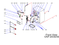
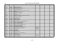
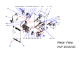
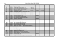
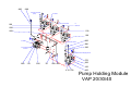
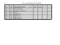
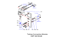
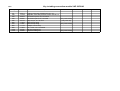
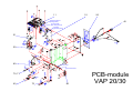
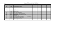
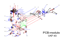
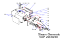
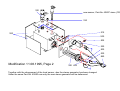
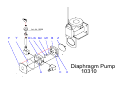
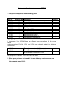
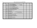
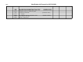
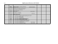
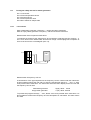
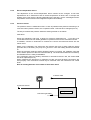
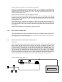
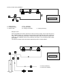
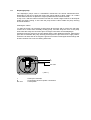
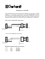
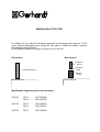
1.
General notes for users of the Service Manual VAP 20/30/40
This manual was written exclusive for the service staff of C. Gerhardt GmbH & Co. KG and for the
service staffs of our international agencies.
This service manual shall help to get a deeper knowledge of how the instruments are constructed and
how they work. It is an important tool to service and repair the instruments in a safe, competent and
specific way. The transparent structure and the appendix of modification information will enable to
order and to store the most useful spare parts. This manual will make servicing easier, in particular for
our international agencies.
To provide yourself against risks during operation or service, the following safety instructions should be
obeyed:
Make sure that no liquid gets into contact with cable connections or the interior of the electrical
parts of the unit! Danger of electrical shock!
Repairs on electrical, electronic or mechanical parts must only be done by authorzied
personnel.
Always switch off the apparatus at the mains and pull the plug before opening! Danger of
electrical shock!
The apparatus must be used according to the instruction manual. It is not allowed to make
changes to the apparatus in order to modify its application.
2 0 0
2 9 0 3 0 0
2 4 1 2 4 0 2 8 0
3 8 0
2 6 1 2 6 0
5 8 0 1 1 0 0 5 0
3 1 1
1 0
4 4 0
2 5 0
2 5 1
2 1 0
2 7 0
5 1
3 3 0
3 4 0
3 2 0
3 1 0
2 0 1 0 2 2 0
1 1 2 0 2 3 0
2 0
8 0
4 5 0
9 9 5
3 5 0
F r o n t V ie w
V A P 2 0 /3 0 /4 0
Date:
Key to Front view VAP 20/30/40
Drawing-No.
Part-No.
10
20
50
51
80
50014
50015
50018
50020
50003
50012
13308
7472
6470
7673
6474
16604
16607
16602
16606
16601
16609
30698
11810
11811
50021
40234
25102
19015
19016
18250
18251
17542
17940
17945
18404
22705
20903
22704
200
210
220
230
240
241
250
251
260
261
270
280
290
300
310
311
320
330
340
350
380
440
450
580
1100
1120
2010
Description
Modif. 1
Case, C.G. yellow
Drip tray PP, VAP 20 - 40
Holder VK/DK VAP 20 - 40
Clamp fitting for 50018
Quick clamping device for sample tube, compl.
Wedge, PP
Switch for clamping device
Distribution head, glass
Viton cone
Distillation condenser
Ventilation valve, PP, for distillation condenser
Screw cap GL 32, open
Silicone seal GL 32
Screw cap GL 18
Silicone seal GL 18
Screw cap GL 14
Silicone seal GL 14, with tubing connection
PTFE - sieve for steam inlet tube
PTFE - inlet tubing, steam
PTFE - inlet tubing, NaOH
Distance piece for distribution head
Tubing holder for H3BO3
Dummy plug for 8mm hole
Plexiglass protection door, bottom
Plexiglass protection door, top
Door hinges
Door handle
PP-tube joint
Rubber foot, 5mm
Rubber foot GF 21, self-adhesive
Cable binder
Silicone tubing 8/16
Silicone tubing 6/10
Silicone tubing 8/12
02.05.96
02.05.96
02.05.96
16.03.95
Page 1
Modif. 2
Modif. 3
Modif. 4
1 1 6 0 4 0 0 3 9 0 3 6 0 4 1 0 1 1 1 0
1 6 3 1 6 21 1 7 01 6 0 1 6 2
4 9 0
1 0
3 7 0
S 3
3 8 5
7
3
4 5 6
4 5 5
1 1 1 0
9 0
S 2
S 3
1 1 7 0
S 2
4 3 0
7 0
1 1 5 0
5
2
4
S 1
8
6
8
S 1
to c o n d e n s e r
3 0
9 9 0 4 8 0 8 1
8 0
2 9 0
9 9 0
4 0
9 9 8
5 2 0
R e a r V ie w
4 8 6
6 0
V A P 2 0 /3 0 /4 0
Date:
Key to Rear View VAP 20/30/40
Drawing-No.
Part-No.
10
30
40
60
70
80
81
90
50014
50016
50017
50019
40850
50003
13308
40890
40891
40892
10385
10389
11003
40269
11811
50024
40249
40239
10318
10317
50023
27309
27310
18411
25121
17914
17920
23230
23002
20914
20920
20921
20919
160
161
162
163
290
360
370
385
400
410
430
455
456
480
486
490
520
600
610
1110
1150
1160
1170
Description
Case, C.G. yellow
Pump-holding module VAP 20 - 40
(see 4.1)
Tubing-connection module VAP 20 - 40
(see 4.2)
Rear cover VAP 20 - 40, C.G. yellow
Steam Generator DE 94
(see 4.5)
Quick clamping device for sample tube, compl.
Switch (Tube present)
PCB-module 230 V, VAP 20, compl.
(see 4.3)
PCB-module 230 V, VAP 30, compl.
(see 4.3)
PCB-module 230 V, VAP 40, compl.
(see 4.4)
Pinch-solenoid valve S 307
Tube holding device for valve 10385
Plug with bridge rectifier for valve 10385
Ventilation vessel, glass
PTFE inlet tube, NaOH
PP - connector
Screw connection, (part 3) for 50024
PP - dummy plug for 50024
PP - connection, bent, DN 08 R 1/8"
PP - connection, bent, DN R 1/8"
Tubing connection, PP, 51x10x5
Silicone - red 15x80x5
(base for Steam Generator)
Silicone - red 15x15x3
(base for Steam Generator)
Guiding spout
Cap Heyco, d = 22,5mm
Band clamp fitting OBO - Quick PG 21
Clamp 12H8074
Set screw VA M4x30 DIN 551
Label for ground connection, M4, 9x18, Al
Silicone-tubing 4x7, from pump H2O to 50024
Verprene-tubing 4x8
Verprene-tubing 8x12
Neoprene-tubing 4,8x1,6 approx. 170mm and 520mm
Modif. 1
Modif. 2
11.08.95
27.09.95
20.06.95
20.06.95
30.03.95
Modif. 3
Modif. 4
9 8 0
8 0 0
to s te a m g e n e ra to r
(re a r)
to 5 0 0 2 4
5
E 1
2
4
to
to
g r o u n d c o n n e c t io n
1 0 0
6 9 0
R e c e iv e r
5
6 6 0
1 0 0
2
1 0 0
E 1
E 2
to
to 5 0 0 2 4
D is t r ib u tio n H e a d
8 0 0
9 8 1
4
6
2 9 0
t o c o n n e c t io n p ie c e
5 1 x 1 0 x 5
E 2
to
S a m p le T u b e C la m p in g D e v ic e
5 7 0
9 9 2
6
6 8 0
1 1 0
9 9 2
3 0
9 9 0
4 8 0
1 0 0
4 1 0
7 0 0
4 0 0
P u m p H o ld in g M o d u le
V A P 2 0 /3 0 /4 0
Date:
Key to pump-holding module VAP 20/30/40
Drawing-No.
Part-No.
30
100
110
290
400
410
480
570
660
680
690
700
800
980
981
50016
10310
10360
11811
10318
10317
18411
22701
18421
18423
17424
18425
11140
20050
20072
Description
Pump-holding module VAP 20 - 40
Diaphragm-pump PML 1140-ND100
Peristaltic-pump SR25 230 V
PTFE - inlet tubing NaOH
PP - connection, bent, DN 08 R 1/8"
PP - connection, bent, DN 06 R 1/8"
Guiding spout
Clamp VZ N10
SES Markers S-9-J/2
SES Markers S-9-J/4
SES Markers S-9-J/5
SES Markers S-9-J/6
Multiple contact strip
Insulation tube sw 6x0,5
Insulation tube sw 5x0,5
(see 6.0)
Modif. 1
Modif. 2
30.03.95
15.12.95
Modif. 3
Modif. 4
8 0 0
8
to s a m p le tu b e
c la m p . d e v ic e
to P o w e r P C B
1 5 0
8
to c o n d e n s e r
4 2 0
to p e r is ta lt ic p u m p (p re s s u re )
4 8 5
4 3 0
to c o n d e n s e r
1 1 0 0
9 9 0
4 0
5 1 0
5 0 0 1 1 5 0
T u b in g C o n n e c tio n M o d u le
V A P 2 0 /3 0 /4 0
Date:
Key to tubing connection module VAP 20/30/40
Drawing-No.
Part-No.
40
150
420
430
485
500
510
800
990
1100
1150
50017
17109
50022
50023
25120
17908
17907
11140
17960
22705
20920
Description
Remark
Tubing-connection module VAP 20 - 40
Magnetic valve with pressure control 0,5 bar, 5 l
Connection piece, PP, 51x10x10
Connection piece, PP, 51x10x5
(only VAP 30/40)
Cap, Heyco, d = 15,1mm
(only VAP 20)
Band clamp fitting
Band clamp fitting
(only VAP 30/40)
Multiple contact strip
VA - screw 1411 KA 50x25
Silicone tubing 8x16
Verprene tubing 4x8
(only VAP 30/40)
Modif. 1
Modif. 2
Modif. 3
1 1
a
1 0
2 0
to p re s s u re s e n s o r
( c o o lin g w a te r )
4 0
1
2
3
to m ic r o
( tu b . c la
to S
g e n
4
5
6
7
8
f1
g 1
s w itc
m p . d
te a m
e ra to
h
e v ic e )
r (fro n t)
f2
rd t
rh a
G e
g 2
5 1
b 1
d
b 2
d
c 1
3 0
s t
d e
p o
V a
e 1
e 2
b 3
2
f2
a
4
1
3
5 0
b 3
b 4
h 1
f1
h 1
h 2
b 4
c 2
8 0
to
re a r c o v e r
to
g r o u n d c o n n e c tio n
c 1
c 2
h 2
7 0 , 7 1
b 1
e 1
e 2
b 2
g 2
6 0
7 2
g 1
9 0
P C B - m o d u le
V A P 2 0 /3 0
Date:
Key to PCB-module VAP 20/30/40
Drawing-No.
Part-No.
10
11222
11225
11223
11227
11213
11214
11215
11750
15350
15351
14401
21417
21420
12703
18690
17916
11
12
20
40
50
51
60
70
71
72
80
new
Description
Control - PCB VAP 20/30
Control - PCB VAP 40
Power - PCB 230 V, VAP 20/30/40
Display VAP 40
Keyboard VAP 20
Keyboard VAP 30
Keyboard VAP 40
Switch, green illuminated
Semiconductor relay WG-A5-6D25
Cap for 15350
Plug connection 161.5, for mains cable
Fuse holder, 16 A
Bayonet type cap for fuse 5x20
(for 21417)
Socket with byonet catch, 3 pin
Plug housing 021 032 660
Clamp fitting
(for tube at pressure sensor)
Modif. 1
Modif. 2
Modif. 3
Modif. 4
2 0
4 0
1 0
1 1
a
1 2
rd t
rh a
G e
to p re s s u re s e n s o r
( c o o lin g w a t e r )
1
2
3
to m ic r o s w itc h
( t u b e c la m p . d e v ic e )
4
5
6
b 1
7
8
d
to S te a m g e n e ra to r (fro n t)
f1
g 1
b 2
b 3
b 4
h 1
f2
g 2
4 0
s t
d e
p o
V a
a
5 1
d
c 1
e 1
e 2
b 3
2
f2
4
1
3
5 0
f1
h 1
h 2
b 4
c 2
8 0
to
re a r c o v e r
to
g r o u n d c o n n e c t io n
c 1
c 2
h 2
7 0 , 7 1
b 1
P C B - m o d u le
e 1
e 2
b 2
g 2
6 0
7 2
g 1
9 0
V A P 4 0
3 2 0
2 1 0
2 0 0
3 3 0
1 4 0
3 1 0
5 0 2
5 3 5
5 1 5
3 0 0
5 0 0
E 2
5 0 5
3 5 0
E 1
5 0 0
5 3 0
8 9 0
E 2
3 4 0
4 0 0
E 1
S te a m G e n e ra to r
V A P 2 0 /3 0 /3 0
3 2 0
n e w
s e n s o r , P a r t- N o . 4 0 8 5 7 s in c e ( 1 2 /9 5 )
3 3 0
5 1 5
3 0 0
5 0 0
E 2
5 0 5
3 5 0
E 1
5 0 0
5 3 0
8 9 0
E 2
M o d ific a tio n 1 1 .0 8 .1 9 9 5 , P a g e 2
3 4 0
4 0 0
E 1
T o g e th e r w ith th e c h a n g e m e n t o f th e le v e l s e n s o r , a ls o th e s te a m g e n e r a to r h a s b e e n c h a n g e d .
U n d e r th e s a m e P a r t- N o . 4 0 8 5 0 n o w o n ly th e n e w s te a m g e n e r a to r w ill b e d e lie v e r e d .
Date:
Key to steam generator VAP 20/30/40
Drawing-No.
Part-No.
140
300
320
330
340
350
400
890
40863
21115
20604
20620
12354
12307
18787
18691
Description
Level sensor
Multitherm 550 HD, 400x500x3mm
Excess-pressure valve, 604T
SKT - Ventilation valve
Tubular heating element, 230 V
Excess-temperature device
Plug-in connection piece + label for ground connection
Plug 020 030 660
Modif. 1
11.08.95
Modif. 2
Modif. 3
Modif. 4
F
A rt.-N r. 1 0 3 2 9
Y
D
L /N
M 2
E
M 1
B
Z
C
K
D ia p h r a g m
1 0 3 1 0
P u m p
Spare parts for diaphragm pump 10310
1) Pump-head comprising of the following parts:
Part-No.
10330
10325
10322
10323
10326
10320
10327
10328
10324
17911
17910
10321
Drawing-No.
F
D
B
C,E
K
Y
M1
M2
L,N
Z
Description
Cover of pump head
Connection-piece for square connections
Distance piece
O-Ring
O-Ring
Diaphragm
Valve plate (PTFE)
Valve plate (stainless steel)
Clamp for valve tiles
Angle-connection (inlet )
Angle-connection (outlet )
Diaphragm with lip and screw
Quantity
1
1
1
2
1
1
2
2
2
1
1
1
Attention !
In instruments Vap 20/30/40 there are different angle-connections for the pump
NaOH.
Angle-connections Part-No. 17911 and 17910 are replaced against the following
connections.
10317
10318
20918
-
PP - angle-connection ( NaOH - outlet )
PP - angle-connection ( NaOH - inlet )
Isoversinic-tubing
see modification 2 from 30.03.1995
For pumps H2O Part-No. 17911 and 17910 are valid.
2) Other spare parts are not available. In case of damage customers only can
order
the complete pump 10310 .
1
1
1
Date:
Spare parts and accessories VAP 20/30/40
Part-No.
18560
18561
18562
18564
18565
18566
18567
18568
18569
26926
26925
22802
25450
25451
20921
22601
22604
1311
7629
7639
7649
6471
4260
4261
4262
4264
4265
Description
PC - Label 67x72: Caution ! Before opening rear wall...
PC - Label 32x50: Pump Suction
(VAP 30/40)
PC - Label 32x50: Pump H2O-sample
(VAP 30/40)
PC - Label 18x36: Cooling water outlet
PC - Label 22x41: Pump NaOH
PC - Label 18x79: Excess-temperature device
PC - Label 18x78: Excess-pressure outlet
PC - Label 32x50: Cooling water inlet with sieve
PC - Label 32x50: Pump H2O-steam generator
PC - Label 95x59: inside the instrument
PC - Label 130x98: rear of PCB module
Water inlet tubing 10/17, 2m
PVC - pipe 6x1
PVC - pipe 10x1
Verprene-tubing 8/12
(for sample waste VAP 30/40)
PVC - tubing 4/7, 2m
(for pumps H2O dist.)
PVC - tubing 8/12, 2m
(for tank NaOH and cooling water outlet)
Mains cable, 2m
Set of tanks KAN20, with level switch
Set of tanks KAN30, with level switch
Set of tanks KAN40, with level switch
Viton cone VK micro, for 100ml tubes KMT
RS 232/485 ARS
Data cable DK 42 for RS 485, 2m
Data cable DK 45 for RS 485, 5m
Data cable DK 22 for RS 232, 2m
Terminator AST
Modif. 1
Modif. 2
Modif. 3
Date:
Modification kit Devarda for VAP 20/30/40
Part-No.
7474
7475
30244
7676
40213
50025
16604
16607
Description
PP - distribution head Devarda, VPD 7, bottom
Distribution head Devarda, glass, VGD 7, top
Ventilation valve for condenser, glass
Condenser, shortened
PP - adaptor
PP - distance piece for distribution head
Screw cap GL 32, open
Silicone - seal GL 32
Modif. 1
(instead of 7472)
(instead of 7472)
(instead of 7673)
(instead of 50021)
Modif. 2
Modif. 3
Date:
Modification kit Bi-dist for VAP 20/30/40
Part-No.
50027
50026
17103
17110
40231
17908
17907
25121
25122
11140
18424
18560
18564
18565
18566
18567
18568
18569
18561
18562
Description
Holder for customer´s Bi-Dist installation
Rear cover C.G.
(instead of 50019)
Magnetic valve without pressure control
Flow control for cooling water, MR 05
Sample outlet, PP transparent
Clamp VZ 12-22/9
Clamp VZ 8/7
(VAP 30/40)
Cap Heyco, d = 22,5mm
Cap, Heyco, d = 34,8mm
(VAP 20)
Multiple contact strip
SES - Markers S-9-J/5
PC - Label 67x72: Caution! Before opening rear cover...
PC - Label 18x36: Water outlet
PC - Label 22x41: Pump NaOH
PC - Label 18x79: Excess-temperature device
PC - Label 18x78: Excess-pressure outlet
PC - Label 32x50: Cooling water inlet with sieve
PC - Label 32x50: Pump H2O-steam generator
PC - Label 32x50: Pump suction
(VAP 30/40)
PC - Label 32x50: Pump H2O-sample
(VAP 30/40)
Modif. 1
Modif. 2
Modif. 3
Date:
Other parts and accessories for VAP 20/30/40
Modification to PP- distribution head
Part-No.
7482
7676
Description
PP - distribution head VAP 20
Distillation condenser VAP 20
Quantity
(instead of 7472)
(instead of 7673)
Modif. 1
Modif. 2
Modif. 3
Modif. 1
Modif. 2
Modif. 3
Modif. 1
Modif. 2
Modif. 3
Modif. 1
Modif. 2
Modif. 3
1
1
Modification to Büchi
Part-No.
7483
Description
Distribution head, glass
Quantity
(instead of 7472)
1
Modification to micro
Part-No.
6471
Description
Viton cone micro
Quantity
1
Modification to acid-restistant
Part-No.
30244
20918
27101
10327
Description
Ventilation valve, glass
(instead of non-return valve 10329)
Isoversinic-tubing 6x12
(instead of PVC-tubing at pump NaOH)
Clamp VA 6-16
(to fasten 20918)
Valve plate PTFE for pump NaOH
Quantity
1
45mm
2
30.03.95
30.03.95
15.12.95
8.0
Steam Generator
8.1
General description of steam generation
After switching-on the Vapodest the electronics measures the level of water inside the steam
generator via the level sensor. In case of a level below minimum, the pump for H2O steam
generator is switched on until the level sensor detects sufficient water inside the steam
generator. This will take some seconds.
Then the semiconductor relay switches on the tubular heating element with maximum power
to reach the necessary steam pressure for the distillation. When this pressure is reached, the
maximum heating power is switched off and the instrument reverts to stand-by with a
regulated and controlled heating. The instrument now is ready for distillation.
When starting a distillation the instrument will heat with a selected power from 30% - 100%
(VAP 20/30) or 40% - 100% (VAP 40). The steam will reach the sample tube via pinchsolenoid valve(s), ventilation glass, PP-distributor and steam inlet tube. During this procedure
the level inside the steam generator will decrease. This is recognized by the level sensor and
the pump H2O for the filling of the steam generator will be switched on. If there is no sample
tube present or if the tap for cooling water is not open, a distillation is not possible.
Remark:
Especially if the water for the steam generator is not very clean or if there any kind of dirt
within the reservoir, the following problem may occur:
- After some distillations the instrument shows the error message „E3“, no water for steam
generator and the program stops.
- After pressing „RUN“ the display shows „H“, wait for steam.
Explanation:
If the steam generator is contaminated with dirt, the boiling and bubbling water will build up
foam above the water level. The level sensor detects the foam as water and prevents the
pump from running even though the water level in the steam generator is not sufficient. After
some time the liquid level or the foam will have diminished to such an extent that no more
liquid is detected, and the system switches on the pump. Within 15 s a sufficient water level
should now be detected. As this is not possible in such a short time the error „E3“ will appear
on the display.
If the „RUN“ key is now pressed, the system will get into the filling mode and the steam
generator will be filled to the height stipulated. However, at the same time, due to the cold
water, the steam pressure collapses, and the unit heats up again until stand-by is reached.
Only now further distillations can be run. So please note that a reaction as described is not a
malfunction, but a sign of unwanted foam in the steam generator. If this happens, clean the
steam generator and the reservoir.
8.2
Safety devices for steam generation
8.2.1
8.2.2
8.2.3
8.2.4
8.2.5
8.2.1
Level sensor
Excess-temperature device
Pressure sensor
Excess-pressure valve
Micro switch for sample tube
Level sensor
The level sensor constantly controlls and regulates the level of water inside the steam
generator.The sensor itself is constantly checked by the electronics; in case of a malfunction,
the instrument will give an error message. If the level detection system fails totally, the tubular
heating element will be switched off in case of a level decreasing under the allowed minimum
range.
The level sensor can only compare between insufficient or sufficient water inside the steam
generator. This is done by changing the frequency it sends to the Control-PCB.
8.2.2
Excess-temperature device
In case that due to a total failure of the level sensor and the control electronics lack of water
in the steam generator cannot be detected, the tubular heating element must be protected
against overheating. In such a case the excess-temperature device will switch off the heating
circuit at about 150°C. After trouble shooting and cooling off of the steam generator the pin of
the excess-temperature device has to be pressed back into position. Now the next distillation
can be started.
8.2.3
Pressure sensor
The pressure sensor is placed directly on the Control PCB and continuously checks the
pressure inside the steam generator. If this sensor detects a higher pressure than 0,45 bar,
the tubular heating element is switched off, and the instrument gives an error message.
8.2.4
Excess-pressure valve
In case of a total failure of pressure sensor and control electronics, the instrument must be
protected against an increasing pressure. At about 0,5 bar the excess-pressure valve will
open mechanically so that any damage of the instrument can definitely be avoided . If this
happens, the instrument has to be switched off immediately.
8.2.5
Micro switch for sample tube
This switch ensures that a distillation is not run without a sample tube. In case you try to start
the system without a sample tube, the start is prevented by the switch. Thus there is no
danger of scalding.
8.3
Testing the safety devices for steam generation
8.3.1 Level sensor
8.3.2 Excess-temperature device
8.3.3 Pressure sensor
8.2.4 Excess-pressure valve
8.2.5 Micro switch for sample tube
8.3.1
Level sensor
With a filled steam generator a frequency < 20 KHz should be measured.
With an empty steam generator a frequency >130 KHz should be measured.
Measurement of the frequencies VAP 20/30:
To measure the frequency the gauge has to be connected to collection plug P4 at pins 2 + 3.
P4 is to be found on the Power PCB, above those orange coloured plugs.The occupation of
P4 is to be found in the circuit diagram (see 4.2).
P4
KHz
8
7
Measurement of frequency VAP 40:
At instruments of the type Vapodest 40 the frequency can be checked with the inbuilt test.
program without opening the rear wall. To enter the test-program the keys „ “ and „ 9 “ have
to be pressed at the same time. The instrument shows the menu display for the I/O Test and
the frequency can be read:
filled steam generator
empty steam generator
.
H(igh) about 5 KHz
L(ow) about 90 KHz
To quit the test-program the keys „ “ and „ Reset “ have to be pressed at the same time. It is
also possible to measure the frequency as in the description for VAP 20/30. The same values
are valid.
8.3.2
Excess-temperature device
The adjustment of the excess-temperature device should not be changed. It has been
adjusted here at C. Gerhardt so that an excess-temperature of about 150° C will open the
heating circuit. This device is directly switched into the the 230 V circuit. A damaged excesstemperature device should not be bridged but replaced immediately.
8.3.3
Pressure sensor
The pressure sensor is maintenance-free. In case of problems with pressure measuring or in
case of a broken pressure sensor, the complete Control - PCB has to be changed (see 10.).
The way to measure the pressure inside the steam generator is as follows:
VAP 20/30
When the Vapodest is still cold, a gauge for pressure measurement 0 - 1 bar has to be
connected into the line from steam generator to pressure sensor as the schematics shows.
If available, connect an instrument to measure the current the instrument draws into the
mains circuit.
Switch on the Vapodest. The electronics will measure the level of water inside the steam
generator and, if necessary, the pump for H2O will run. Then the heating element is switched
on.
When the pressure inside the steam generator begins to increase, the ventilation valve will
close, and the pressure of about 0.2 bar will build up. The instruments switches into stand-by
and indicates that it is ready for distillation.
If the instrument goes into stand-by well below or well above than 0.2 bar, the Control-PCB
has to be replaced (see 10.).
When measuring the pressure it is important to make sure that all tubing connections are
fixed properly. The connections should only be loosened when the instrument has cooled
down:
Risk of scalding because of hot steam of more than 100°C!
to steam valve
bar
to pressure sensor
steam generator
H2O steam generator
VAP 40
At instruments of the type Vapodest 40 the pressure can be checked with the inbuilt test.
program without opening the rear wall. To enter the test-program the keys „ “ and „ 9 “ have
to be pressed at the same time. The instrument shows the menu display for the I/O test. The
pressure as measured by the pressure sensor can now be read.
.
To quit the test-program the keys „ “ and „ Reset “ have to be pressed at the same time.
8.3.4
Excess-pressure valve
The adjustment of the excess pressure valve should not be changed. It has been adjusted
here at C. Gerhardt so that an excess-pressure of about 0.5 bar will activate the valve.
The following instructions will help to adjust the excess-pressure valve if it becomes
necessary nevertheless.
When the Vapodest is still cold, a gauge for pressure measurement 0 - 1 bar has to be
connected to the steam generator as the schematics show. The tubing to the pressure
sensor is left without any connection to prevent the switching off of the heating when reaching
a pressure of 0.2 bar.
If available connect an instrument to measure the current the instrument draws into the
mains circuit.
to steam valve
bar
to pressure sensor
X
steam generator
H2O steam generator
Switch on the Vapodest. The electronics measures the level of water inside the steam
generator and, if necessary, the pump for H2O will run. When a sufficient water level is
reached the heating element is switched on.
When the pressure inside the steam generator begins to increase the ventilation valve will
close, and the pressure is able to increase more and more because of the disconnected
pressure sensor. Observe carefully the increasing pressure, and make a note at which
pressure the excess-pressure valve opens. In case that the valve does not open at a
pressure of about 0.5 bar, immediately switch off the instrument!
Excess-pressure valve has to open earlier (lower pressure):
Remove the brass cap and slightly loosen the big nut. Turn the adjusting screw slightly anticlockwise, and tighten the nut very well. Take care that the adjusting screw stays in the
adjusted position. When the adjustment is done, repeat the above described procedure to
test the excess-pressure valve.
Excess-pressure valve has to open later (higher pressure):
Remove the brass cap and slightly loosen the big nut. Turn the adjusting screw slightly
clockwise, and lock the nut very well. Take care that the adjusting screw stays in the adjusted
position. When the adjustment is done, repeat the above described procedure to test the
excess-pressure valve.
When measuring the pressure it is important to make sure that all tubing connections are
fixed properly. Carefully observe the increasing pressure and make sure you do not touch the
hot excess-pressure valve. The connections should only be opened when the instrument has
cooled down:
Risk of scalding because of hot steam of more than 100°C!
8.3.5
Micro switch for sample tube
This switch prevents the start of a distillation without any sample tube. Without a tube the
switch is activated, which means that the circuit is open. With a sample tube the switch is not
activated, and the circuit is closed.The switch is located inside the instrument directly fixed on
the clamping device for the sample tube.
8.4
General description of steam inlet / sample suction
Steam inlet:
During stand-by steam of about 0.2 bar only reach the steam valve. During stand-by both
valves, steam valve and shut-off valve are dead. After starting a distillation, the steam valve
gets alive which means it will open. The ventilation valve however, still stays dead, so that it
is open for steam. The steam now can pass through the steam valve, ventilation glass, shutoff valve, PP-distributor and steam inlet tubing into the sample tube. From there the distillate
will pass through the distribution head and the condenser into the receiver. The ventilation
valve of the condenser must be closed. The steam can also pass through the PP-distributor
until it reaches the pump for sample suction. Steam will also pass through the tubing for the
dilution of the sample until it reaches the non-return valve of the pump for H2O sample.
a) Way of steam during stand - by
3
2
1
4
5
Steam Generator
6
7
b) Way of steam during distillation
2
3
1
4
5
Steam Generator
6
7
1 = Shut-off valve
2 = Ventilation glass
3 = Steam valve
4 = PP - connector
5 = Inlet tube steam
6 = Tubing H2O sample
7 = Tubing suctioning
Sample suction:
After the distillation the steam valve will not draw current any longer, and it closes the path to
the ventilation glass. For suctioning now the shut-off valve will get alive and it closes the
tubing. too. Consequently the pump for sample suctioning is able to empty the sample tube.
In this case the ventilation valve of the condenser must open. If not, the pump will also empty
the receiver.
The pump for sample suction also draws against the pump for sample dilution.
3
2
1
4
5
Steam Generator
6
7
8
9
sample tube
8 = Pump suctioning
9 = Pump H2O sample
9.1
Diaphragm pump
The diaphragm pumps used in VAPODEST instruments are almost maintenance-free.
Depending on the kind of liquid the volume the pumps deliver is about 100ml / 10 s. Make
sure that the tanks are not placed in a higher position than the instrument itself.
It may occur that the volume becomes less than the normal range because of dirt deposit
inside the pump housing. In this case the pump and the valves inside the pump housing
should be cleaned.
Cleaning the valves:
To clean the pump it is necessary to disconnect all the tubes and to remove the rear wall.
Loosen the 4 screws from the badly working pump, and take away the cover of the pump
head. Also take away the connection-piece for angle connections and the diaphragm.
Carefully loosen the clamp for the valve plates and the valve plates themselves. Clean all the
parts and re-assemble the pump ensuring that all parts are put back into the right position.
Close the rear wall, and do not forget the ground connection! Install again all the tubings and
let the instrument run to see if everthing works well.
L
D
M1 / M2
( see 6. )
L
D
M1 / M2
= Clamp for valve tiles
= Connection piece for square connections
= valve plates
9.2
Peristaltic pump
Also the peristaltic pumps are maintenance-free. At least once a year the neoprene tubing
should be replaced:
- Remove inlet and outlet tube
- Twist s-shaped bar on the left hand side of the pump
- Take out the plastic housing containing the tubing
- When fitting the new tubing ensure that the u-shaped lugs locate in their recesses to fix the
tube into the plastic housing
- The complete plastic housing is now inserted into the guides of the pump body before
locking in position with the S-bar
S-shaped bar
Description
Plastic housing for tubing
Spare tubing Neoprene
Guides for the pump body.
S-shaped locking bar
plastic housing
Part-No.
10327
10370
10371
10373
Replacement of the Control PCB
With the new Vapodest 20/30 it is possible to exchange the Control PCB from a Vap 20 to a
VAP 30.
In case of a service it will now be easier to have the right PCB on stock because now it does
not matter any longer if the PCB is for a VAP 20 or for a VAP 30. The software will check
which keyboard is present, and then the processor will adapt the PCB.
In order to ensure that the software will work after the replacement of the Control PCB it is
necessary to press „PROG“ and „RESET“ at the same time and to switch on the instrument
while still pressing the keys.
Modification 16.03.1995
Draw.-No. 1120
Part.-No. 20903
The tubing with part-no.: 20903 is shortened to a length of 150 mm. When installing the
shortened tubing the angle has to be adjusted to the angle of the condenser outlet.
adjust angle of tubing
Modification beginning with series numbers:
VAP 20 from VAP 000233
VAP 30 from
VAP 000182
Modification 1 from 30.03.1995
Draw.-No.:
Part-No.:
1150
20920
only VAP 30/40
The silicone-tubing part-no. 20914 from pump H2O to PP-distributor is replaced against
Verprene-tubing Part-No. 20920.
Additionally there is clamp Part-No. 17907 used. It fixes the new tubing to the PP-distributor.
Modification beginning with series numbers:
VAP 20 from VAP 000242
VAP 30 from VAP 000183
Modification 2 from 30.03.1995
Only diaphragm pump NaOH, Part-No. 10310!
The PVC-tubing between PP-angle connection (10317) and the PVC non-return valve (10329)
is replaced against Isoversinic-tubing part-no. 20918.
The other diaphragm pumps are not modified.
Additionally there are 2 clamps Part-No. 27101 used to fix the new tubing on both ends.
Modification beginning with series numbers:
VAP 20 from
VAP 000242
VAP 30 from
VAP 000183
Modification 20.06.1995
Draw.-No.:
Part-No.:
160, 163
10385, 40269
Due to modifications of the solenoid pinch valves the following kit is to be used for
replacement:
Modification-kit part.-no.: 2/760050
2. After modification ventilation glass part-no. 40269 is replaced by ventilation glass part-no
40272.(Part of modification kit)
Modification beginning with series numbers:
VAP 20
230 V
240 V
VAP 000294
VAP 000180
VAP 30
230 V
240 V
VAP 000379
VAP 000173
VAP 40
230 V
VAP 000349
Modification 11.08.1995
As the technology of the new level-sensors has changed, they now have 4 contacts
instead of 3. If you have to install one of the new sensors/boilers into older
instruments, you will have problems with the connections at VAP 20/30. In order to
do so you have to modify the cabling between the power PCB and sensor plug.
Depending on the cabling of the sensor there are two possible ways of modification:
Older version: cabling white, brown, green
1
green
brown
white
1
P1, sensor PCB
P4, VAP 20-40
power PCB
ground, boiler
Newer version: cabling blue, brown, black
1
1
black
brown
blue
P1, sensor PCB
P4, VAP 20-40
power PCB
ground, boiler
Modification beginning with series numbers:
VAP 20
VAP 30
VAP 40
230 V
240 V
230 V
240 V
230 V
VAP 000279
VAP 000180
VAP 000361
VAP 000173
VAP 000346
Modification 27.09.1995
As adaptor for the outlet of the steam generator a connection piece part-no. 17915
and a silicone-tubing(6x10 mm, lenght 45 mm) part-no. 20903 are used to connect
the Neoprene-tubing 20919.
Of the original Neoprene-tubing you have to cut off 45 mm.
Old version
New version
Neoprene
20919
Neoprene-tubing
Connector
17915
Silicone
20903
Steam generator
Steam generator
Modification beginning with series numbers:
VAP 20
230 V
240 V
VAP 000294
VAP 000180
VAP 30
230 V
240 V
VAP 000379
VAP 000173
VAP 40
230 V
VAP 000349
Modification 15.12.1995
Diaphragm pump 10310 NaOH
Only acid-resistant version !
The valve plates made of stainless steel (10328) are replaced by valve plates made
of PTFE No. 10327.(see 6.)
Already modified pumps get the part-no. 10311