1
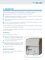
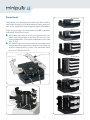
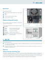
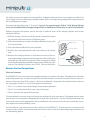
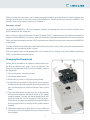
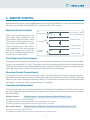
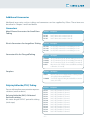
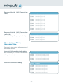
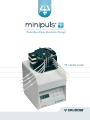
Pulse-Free Flow Peristaltic Pump! User's Guide Table of Contents Warranty Gilson warrants this product against defects in material under normal use and service for a period of 12 months from the date of purchase. 1 Introduction Unpacking Safety 3 3 3 2Description Introduction Speed Control Module Pump Head Back Panel Membrane Keypad Assembly 5 5 5 6 7 7 3 Set Up Electrical Changing the Pump Head Tubing - Selection and Fitting Recommendations Gilson Connectors and Couplers 7 7 9 10 16 16 4Operation Keypad Functions Initialization Autostart Function Maintenance and Troubleshooting 18 18 18 19 20 5Remote Control Electrical Contact Control Control by Gilson Devices Microcomputer Control (GSIOC) 21 21 22 22 6 Appendices Part Numbers and Accessories Additional Accessories Technical Data 26 26 27 30 Gilson is not responsible for incidental damage resulting from physical shock, continuous exposure to corrosive reagents or technical handling not in accordance with the guidelines described in the user’s guide. This instrument must not be directly connected to humans for any purpose! Trademarks Elgiloy® is a registered trademark of Elgiloy Co. Hastelloy® is a registered trademark of Haynes. MS-DOS®, Windows® are registred trademarks of Microsoft Corp. Pharmed®, Isoversinic® are registred trademarks of Norton Performance Plastics Corp. Teflon®, Tefzel®, Viton®, are registred trademarks of E.I. du Pont de Nemours & Co, Inc. -2- ENGLISH 1 - INTRODUCTION This User’s Guide describes how to set up and operate a Gilson MINIPULS 3 Peristaltic Pump. It also describes some of the methodology required to obtain accurate reproducible results. The user must know how to set up and operate a Minipuls 3, before the unit is used, therefore Chapters 1 to 4, including the safety notes, must be read first. The instrument is designed to be used only by properly qualified and trained personnel. Chapter 1 contains general information including the specifications and safety notes. Chapter 2 contains a detailed description of the hardware. Chapter 3 describes how to set-up a pump and details the recommended connectors and tubing. Chapter 4 describes how to operate the pump. Chapter 5 contains information concerning remote control including how to make the electrical connections to other instruments and GSIOC instructions. Chapter 6 is an appendix containing details of the accessories and the technical data. Unpacking Each complete Minipuls 3 is shipped in two boxes. Box 1 contains the speed control module and the standard accessory package (see the Appendix). Box 2 contains the pump head from the six available models (see the Appendix). Additional speed control modules including the standard accessory package (Box 1), or additional pump heads (Box 2) may be ordered separately. Upon receipt of your Minipuls 3, unpack it and check that all of the parts are included even if it is not for immediate use. Keep the packing, because in the event that the unit is returned to the factory the original packing must be used to return equipment under warranty. Report any loss or damage immediately. Safety Read this section carefully before installing and operating the equipment. The instrument described in this User’s Guide is a low pressure pump that should only be used in the laboratory or similar indoor environment, by qualified personnel. If the instrument is used in a manner not specified by Gilson, the protection provided by the instrument may be impaired. -3- For safe and correct use of the instrument, it is essential that both operating and service personnel follow generally accepted safety procedures as well as the safety instructions given in this User’s Guide. Cleaning, installation, dismantling, maintenance, adjustment and repair should only be performed by personnel trained in such work, and who are aware of the possible dangers involved. Voltages present inside the instrument are potentially dangerous. If there is a problem with the instrument, the power cable should be removed until qualified service personnel have repaired it. This is to prevent anyone from inadvertently using the instrument, thus causing possible harm to themselves or damage to the instrument itself. The leakage current of the instrument is within the limits allowed by safety standards of laboratory equipment. An efficient ground connection is imperative for the physical protection of the user. Power supply cord reference 7080316106 is for use in France and Germany. Power supply cord reference 7080318107 is for use in USA and Canada. For other countries contact your local Gilson representative. You must only use the type of fuse described and specified in this document: 0.5 Amp type “T” slow blow is for use with power supplies between 100V and 120V, 0.25 Amp type “T” slow blow is for use with power supplies between 220V and 240V. Adequate protection such as ventilation must be provided if dangerous liquids are used in the analytical work. If incidental spillage occurs, carefully clean-up the spillage, taking into account the nature of the spilled liquid, including all required safety measures. This instrument must not be sterilized, using an autoclave, or any other mechanical device. When you need to clean this instrument, use one of the three following methods: 1 - A clean dry cloth. 2 - A cloth dampened with water. 3 - A cloth dampened with soapy water. No other form of detergent or chemical may be used! If a cloth dampened with soapy water is used to clean the instrument, only domestic soap may be used. When operating the MINIPULS you must ensure that the fan works and that the ventilation slots are not obstructed in any way. The following symbols appear on the instrument: Symbols used on the rear panel are explained in Chapter 5. The keypad symbols are explained in Chapter 4. -4- Symbol Explanation Alternating current Protective Conductor Terminal On (Supply switch) Off (Supply switch) Caution, risk of electric shock Caution (refer to User’s Guide) ENGLISH 2 - DESCRIPTION Gilson’s Minipuls 3 is a peristaltic pump, designed for transferring fluids with a high level of speed stability and a low pulsation level. It has many applications, including the following: transferring solutions, emulsions, suspensions, and gases at up to 200 °C. propelling liquids through chromatographic systems against a back-pressure of up to 500 kPa (for example, when controlled by a Gilson fraction collector. automation of biological analyses by proportionally mixing a sample with several reagents (flow injection analysis). continuously sampling the components of a production process (reactors, fermenters, and so on). formation of gradients (concentration, pH, and so on). The Gilson Minipuls 3 is powered by a hybrid stepper-motor and controlled by an integral microprocessor by using the front-panel keypad (see Chapter 4). It can also be remotely controlled from a master device, such as a Personnal Computer, or by electrical contacts (see Chapter 5). Introduction The main components are as follows. The speed control module containing a die-cast sub-chassis onto which is mounted the steppermotor, and its controller board (microprocessor). An interchangeable pump head. A back panel assembly consisting of an L-shaped plate onto which are mounted the power supply assembly, the cooling fan, and control sockets. A keypad and LCD unit. Speed Control Module The figure shows a general view of a MINIPULS 3, before the head is installed. LCD -5- Keypad Controller Pump Head R1 Pump Head Pump heads are composed of a rotor with idle stainless steel rollers that press a flexible piece of tubing against a cam. In this way liquids are pumped by a peristaltic effect. There are two types of pump heads: the MP (standard) and the HF (High Flow) series. MP models have one, two, four, or eight channels, ten rollers and accept tubing size from 0.2 mm to 4 mm (internal diameter). The maximum back pressure is 500 kPa (75 PSI). HF models have two or four channels, five rollers and accept peristaltic tubing from 2 mm to 8 mm (because of the V-clamp locking system). The maximum back pressure is 300 kPa (45 PSI). Locking key R2 Pump Head R4 Pump Head Adjustment screw R8 Pump Head Compression cam Trigger key R2/HF Pump Head R4/HF Pump Head Fixed bar Mobile retaining bar Fixed bar -6- ENGLISH Back Panel Fan The back panel holds: a power cord socket and a power switch (with fuses) a fan an input/output control socket a 9-pin GSIOC socket. Membrane Keypad Assembly The membrane keypad assembly is integrated with the main housing. Power switch Voltage selection The keypad and liquid crystal display are shown in the figure. SlowerDecrease the pump speed FasterIncrease the pump speed RabbitSet speed to 48 rpm ForwardsStart the pump clockwise BackwardsStart the pump counter clockwise StopStop the pump GSIOC control Input/Output control LCD 3 - SET-UP Keypad Controller This chapter contains: Key information relating to voltage selection and fitting the fuses. You are strongly advised to read this information carefully. Detailed information relating to fitting the tubing, flowrate selection, and which connectors or couplings should be used. Electrical Voltage Selection and Fitting Fuses The power receptacle includes an ON/OFF switch and a fuse holder/voltage selector. The voltage is selected by removing the fuse holder, inserting two fuses of the correct value into the fuse holder, and then inserting the fuse holder into the power receptacle so that the small white arrow corresponding to the required voltage points to the alignment mark on the power receptacle body. -7- For safety reasons, the speed control module is shipped without the fuses having been installed. You must install two fuses of the type specified below and set the operating voltage that corresponds to the available power supply. Two packs of slow-blow type ‘T’ fuses are supplied: for operating at 100 V to 120 V fit two 500 mA fuses (ref: 6730054006) or for operating at 220 V to 240 V fit two 250 mA fuses (ref: 67300240062). Before connecting the power cord to the unit, install two fuses in the voltage selector and set the voltage as follows: 1) Pull the voltage selector out of the power receptacle located on the lower left-hand corner of the back panel. 2) Pull out the drawer as shown in the figure before inserting the fuse into the clips. ON/OFF switch 3) Push the drawer and the fuse into position. Power receptacle 4) Perform the same operation for the second fuse on the other side. 5)Reinsert the voltage selector so that the arrow next to the required operating voltage points downwards to the small white rectangle on the power receptacle. When correctly installed the text indicating the required voltage range will be the right way up. The voltage is factory set to 220 V - refer to the figure. Fuse holder Voltage selector Remote Control Connections Electrical contacts The MINIPULS 3 can be started and stopped remotely using electrical inputs. The direction of rotation and pump speed may also be changed. The electrical contacts are made using the barrier strip connector on the rear panel. The contacts, which are numbered 1 through 6, have the functions listed on the next page. Contacts 2, 4, and 6 are ground connections. • Pair 1-2 is a contact input that changes the pumping direction. • Pair 3-4 is a contact input that starts/stops the pump. • Pair 5-6 controls the speed of the pump. The connections are made using insulated wire and barrier strip connectors. To prepare wire for each connection, cut it into pieces of appropriate length, then strip about 1 cm of insulation from each end. Insert each wire into the appropriate slot on the barrier strip connector. Push each wire all the way in, then tighten the corresponding screw. Push the barrier strip connector into the socket on the MINIPULS 3. The connector is designed to fit snugly into the socket. Connect the other ends of the wires to the corresponding output terminals on the controlling device. -8- ENGLISH Make sure that the connectors are inserted correctly by referring to the diagram, which indicates the function of each pair, on the rear panel of the MINIPULS 3. Details of how to connect a MINIPULS 3 to specific Gilson Instruments are given in Chapter 5. Computer control To control the MINIPULS 3 from a computer, connect an appropriate Gilson interface module, or an RS232 adapter to the computer. Next, connect a Gilson Serial Input/Output Channel (GSIOC) cable between the interface module (or adapter) and the MINIPULS 3, and any other Gilson devices that are controlled from the same computer. The 9-position female plug on the GSIOC cable connects directly into the male socket on the MINIPULS 3 rear panel. The type of interface module used, and details of how the various units in the system are interconnected, depend on the complexity of the system. The user should refer to the appropriate user’s guide and to Chapter 5 for more details relating to GSIOC connections and commands. Changing the Pump Head Follow these procedures to replace a pump head. For the first installation only steps 2 to 6 are relevant. The head can be replaced with any of the models listed in the Appendix. 1) Unscrew the two mounting screws. 2) Lift-off the pump head. 3) Place the two screws on the new pump head. 4)Install the pump head on top of the speed control module in the desired position; four are possible. Do not use the position in which the drain tube is at the front. 5) Turn the roller barrel so that the slot at the bottom of the barrel matches the black tenon of the speed control module. Turning the barrel gently back and forth can help the user to engage it with the tenon. When these two parts are properly engaged, the base of the pump head rests on top of the speed control module. 6)Slide the pump head so that the two screws fall into their inserts and then tighten the two screws; do not over-tighten. -9- Tubing - Selection and Fitting Introduction There is a small Isoversinic drain tube inside the MINIPULS 3, with an outlet at the base of the pump. The tube, which limits the risks resulting from a rupture of the peristaltic tubing, is connected to the motor assembly to prevent liquid from seeping inside the instrument. All other tubing is fitted to the pump head. Gilson supplies two types of tubing: - peristaltic tubing with two retaining stops, - connection tubing without retaining stops. In normal operations, short lengths of peristaltic tubing are placed in the pump head. With MP pump heads, it is essential that peristaltic tubing with two retaining stops is used. The calibrated stops ensure that the tubing is correctly tensioned when fitted to the head. HF models can use either type of tubing. The user then links the MINIPULS 3 with other hydraulic components of the system (for example chromatographic columns) using connection tubing, connectors, and couplers of appropriate diameter and material. Type of Material Tubing made of various materials and with different internal diameters is available from Gilson. The tubing sizes and materials, recommended for MP and HF pump heads are shown in the above table. Tubing sizes are specified as internal diameter (id) in millimeters (mm). Maximum flow rates are specified in milliliters/minute. Recommended Tubing (by Flow Rate) MP Models FlowConnecting Type mL/min. mm (id) PVC Fluoroelastomer Silicone Polypropylene up to 26 0.25 to 3.2 up to 38 0.5 to 4 up to 45 0.6 to 2.8 up to 14 0.5 to 2 HF Models FlowConnecting mL/min. mm (id) up to 236 2 to 8 - 2 to 6 up to 200 2 to 7 up to 171 2 to 6.4 For any given type of pump head, the type of solution pumped determines the type of peristaltic tubing to be used (refer to the table on page 11). More rigid materials, such as PVC, produce smaller pulsations. For example, when pumping water at 45 rpm (pressure = 100 kPa) typical values for pressure pulsations are 5% with 6 mm (id) PVC tubing and 20% with 6 mm (id) silicone tubing. - 10 - ENGLISH Diameter and Flow Rate Select the peristaltic tubing diameter that gives the desired flow rate by reference to the Speed/Flow Rate Charts (page 13 to page 15). These graphs represent the values obtained in laboratory tests, where the liquid was allowed to flow freely from the tubing against atmospheric pressure only. There was no additional back-pressure (e.g. a chromatographic column). The selection of peristaltic tubing is a compromise between minimizing the pulsations and maximizing the lifetime of the tubing. When making this choice, the following points should be considered: - the smaller the diameter, the smaller the pulsations and the faster the head has to rotate, leading to a reduction of peristaltic tubing lifetime - the bigger the diameter, the bigger the pulsations, and the slower the head has to rotate, leading to increased peristaltic tubing lifetime. That is, the pulsations increase when the flow rate decreases, and when the internal diameter of the tubing increases. Recommended Tubing (by Application) Material PVC Silicone Polypropylene CompositionPolyvinyl chloride. Silicone elastomer.Polypropylene-based material with plasticizer. Isoversinic (Viton) Fluorinated elastomer. Physical characteristicsTransparent, clear, rigid.Translucent, beige.Opaque, beige.Opaque, black. Temperature rangeUp to 94°C.Up to 230°C. -60 to 135°C. Standard FDA food quality (FDA 21 CFR 177.26000 USP class VI). -20 to 200°C. Gas PermeabilityLow. High.Low. Impermeable to most gases. Sterilization Autoclaving or irridiation. Autoclaving. Autoclaving. 0.64 to 7 mm. 0.5 to 6.4 mm. 0.5 to 6.0 mm. Autoclaving. Range of internal diameter 0.25 to 8 mm. Other featuresLow cost.Excellent biocompatibility.Long service life.Excellent resistance to strong acids, Not recommended with strong oxidizing agents, aromatic and acids, bases or solvents. chlorinated solvents. Applications General use. Biological.Pharmaceutical and food. - 11 - Where high chemical resistance is required (e.g. ICP). Fitting the Tubing Locking key Adjustment screw MP pump heads Trigger key Only peristaltic tubing with retaining stops can be fitted to MP pump heads. 1) Unlock each channel of the head by pressing the trigger key (A) towards the roller barrel. 2) Position the tubing around the rollers; it is kept in place by the plastic stops (B). 3)Swing the compression cam back and snap the locking key. Do this one-by-one for pump heads with more than one channel. Compression cam HF pump heads Peristaltic tubing with retaining stops: 1) Unlock each channel of the head by pressing the trigger key (A) towards the roller barrel. 2) Position the tubing around the rollers; they are kept in place by the plastic stops (B). 3) One by one, swing the compression cams back and close the locking keys. Peristaltic tubing without retaining stops: Locking key The peristaltic tubing is kept in place by clamps. The movable retaining bar (C) must be fitted in such a way that the large triangular pathways are on the side of the fixed bar. To fit the tubing, use the same procedure as above. Adjustment screw Trigger key Because the MP2/HF and MP4/HF pumps are equipped with 5 rollers rather than the 10 rollers as on the other heads, pulsations may be observed at the end of the tubing. Fixed bar - 12 - Mobile retaining bar ENGLISH Flow Rate Selection & Adjustment Selection The following charts may be used to select the approximate pump head speed (rpm) that is required to achieve the desired flow rate. If it is possible to choose between tubings of different sizes (refer to the Appendix), select a middle range tubing that gives a middle range speed. Adjustment Adjust the cam pressure on the tubing to the minimum necessary to ensure pumping of the liquid. The compression cam pressure can be adjusted using the adjustment screw. Slowly tighten the screw until the pump starts pumping liquid inside the peristaltic tubing, and then tighten again approximately 1/8 turn. Take care not to over-tighten the screws; it is advisable to limit pressure on tubing to the minimum necessary for pumping liquid. Carry out final adjustment after 15 minutes of operation. If the pump is used with a system that provides a back-pressure (such as a chromatographic column), tighten the screw by one or two extra turns, to obtain the required flow rate. 2 2 MP Model - Small Sized Tubing mm .5 r0 me o t s ela oro m Flu .6 m e0 con Sili mm 0.5 ne pyle o r p mm Poly 0.5 PVC 1 1.5 1 0.5 0.5 PVC 0.2 mm 0 0 Flow (mL/min) 1.5 0 10 20 30 Pump Head Speed (RPM) Speed/Flow rate Chart (Small Sized Tubing) - 13 - 40 50 30 30 m C PV MP Model - Medium Sized Tubing 3m 25 25 20 Flow (mL/min) 20 mm C2 PV 15 lene ropy p Poly 15 2 mm 10 10 e 1 mm Polypropylen 5 5 PVC 1 mm 0 0 10 20 0 40 30 50 Pump Head Speed (RPM) Speed/Flow rate Chart (Medium Sized Tubing) 300 300 HF Model - Large Sized Tubing 250 C8 PV mm Flow (mL/min) 200 250 200 PVC 150 lene ropy p Poly 6m 6.4 m mm 5m PVC 150 m 100 100 50 50 0 0 0 10 30 20 Pump Head Speed (RPM) Speed/Flow rate Chart (Large Sized Tubing) - 14 - 40 50 ENGLISH 40 40 m 4m HF Model - Fluoroelastomer Tubing 30 30 m Flow (mL/min) 3m 20 20 10 10 0 0 0 20 10 30 Pump Head Speed (RPM) 50 40 Speed/Flow rate Chart (Fluoroelastomer Sized Tubing) 200 m 6m 150 Flow/mL/min) 200 m 7m HF Model - Silicone Tubing 150 m 5m 100 100 50 50 3 mm 2 mm 0 0 10 30 20 Pump Head Speed (RPM) 0 40 Speed/Flow rate Chart (Silicone Sized Tubing) - 15 - 50 Recommendations To ensure that consistent and accurate flow rates are maintained, systematically replace peristaltic tubing as soon as it appears to be worn. You can reduce wear on the tubing by running at slower speeds, by using tubing of a larger diameter, or by slackening the adjustment screws. Conversely, you should tighten the adjustment screws to reduce the level of pulsations, which may also be reduced by applying some back pressure, or by selecting a more rigid tubing material, like PVC. When the pump is not in use, release the compression cams by pressing on the bevelled corners of the trigger key and slacken the tubing. This increases the life of the tubing. Two small pieces of Isoversinic tubing are supplied in the standard accessory package. Fit one piece to the pump head by pushing it onto the drain tube. The purpose of the drain tube is to remove liquid from the pump head if the flow tubing breaks; it limits the risk of liquid seeping into the speed control module, which contains the motor and electronic circuitry. To prevent liquid from leaking in the event of a tube breaking, install the pump at a higher level than the tank and collector. This arrangement eliminates gravitational flow. If the pump is used as part of a system where a back pressure is present (for example, against a chromatographic column), the adjustment screw must be tightened by one or two extra turns to enable the liquid to flow. Where back pressure is present, the maximum flow rates are less than the values that can be measured from the charts, which are plots of values measured at atmospheric pressure (refer to pages 13 to 15). Use the RABBIT key to prime the tubing (fill it with liquid); see Chapter 4. Gilson Connectors and Couplers With reference to the Appendix (Additional Accessories), Gilson can supply connectors (see table, below) for linking peristaltic tubing with connection tubing, and couplers for other equipment, such as low-pressure liquid-chromatography columns. Connectors Tubings are connected by simply pushing the tubings onto either end of a connector. Plastic connectors are used for the larger diameter tubings. Three types are available: - F1179941, small bore (1 to 2 mm) to small bore, - F1179931, small bore (1 to 2 mm) to large bore (2 to 3 mm), - F1179951, large bore (2 to 3 mm) to large bore. Metal sleeve connectors are used for very small bore tubing. Three sizes are available from Gilson for connecting tubing from 0.25 mm id to 0.8 mm id. - 16 - ENGLISH Tubing ID 0.25 0.3 - 0.5 0.6 - 0.8 1 - 2 2 - 3 0.25 Sleeve (0.6 od) 0.3 - 0.5 Sleeve (0.8 od) 0.6 - 0.8 Sleeve (1.1 od) 1 - 2PlasticPlastic 2 - 3Plastic Coupling Kits These are used to connect the peristaltic tubing to PTFE tubing having flanged ends, or to connect the peristaltic tubing to Low Pressure Liquid Chromatography (LPLC) systems. The coupling kit consists of a connection screw and a cone. The figure shows a typical connection to an LPLC system. A Tefzel connector (reference 495051) is available for connecting flexible tubing (id 1 to 3 mm) to tubing connections screws at Gilson chromatography column outlets. Couplers Two types of coupler are available. Reference F1410050 consists of a set of five PVDF couplers for linking two standard Gilson connection screws (1/4”-28 TPI). Reference 495036 consists of one Teflon coupler for linking connection screws of different sizes (1/4”-28 TPI to 10 mm standard thread). - 17 - 4 - OPERATION Install the pump and make the required hydraulic and electrical connections, as described in Chapter 3. Switch the pump on using the rear-panel switch. Then refer to the following sections, which describe how to use the keypad to control the pump, or to Chapter 5 if the pump is to be remotely controlled. Keypad Functions The keypad has six keys plus a 3-digit and 2-symbol Liquid Crystal Display unit. The keypad functions are summarized below. SlowerDecrease the pump speed FasterIncrease the pump speed RabbitSet speed to 48 rpm ForwardsStart the pump clockwise BackwardsStart the pump counter clockwise LCD StopStop the pump Keypad Controller Initialization 1)Install tubing as described in Chapter 3. 2)Switch the pump ON using the rear panel switch. The speed is set at 12.5 rpm at delivery. The last speed set before switching off is shown in rpm on the keypad display. 3)Select the desired speed by pressing: the (-) key to decrease the displayed value, the (+) key to increase the displayed value. Pressing either key once changes the right-hand digit by one; pressing the key continuously makes the speed vary at an increasing rate. 4) To start the pump, press the or the key, depending on the desired direction of rotation. A (+) sign or a (+) sign is then displayed to the left of the speed value. - Press the RABBIT key to purge or to prime the tubing. The RABBIT key cannot be used until either the or the key has been pressed. The direction of pumping can be changed without stopping the pump. - Pressing the RABBIT key gives the maximum speed of 48 rpm in the previously selected direction. - 18 - ENGLISH When pressed, the display shows (+ - - -) or (- - - -), but the previous speed is stored in memory. If pressed a second time, the pump rotates at the preset speed; the same is applicable if either the or the key is pressed. - The STOP key stops the pump and stores the displayed speed for the next start up command. If the key is pressed when the pump is revolving at the RABBIT speed, the last speed selected before RABBIT selection is stored for the next start up command. - When the pump is remote-controlled, a symbol is displayed above the (+) or (-) sign. Autostart Function The Autostart Function enables the pump to restart pumping at power on, in a predetermined way. When the power is restored, the pump idles regardless of its status when the power was cut. The display flashes until any key is pressed. The Autostart Function has three modes, as described in the next three paragraphs; mode selection is described in the following paragraph. Non-autostart Mode This mode is indicated by a dash “‑” to the left of the identification number. In this mode, each time the speed is changed the current speed is stored in non-volatile memory (provided no other key is pressed within three seconds of selecting the speed). Subsequently, when the pump is switched on, the previously selected speed is shown on the display. The pump operates at this speed when either the or the key is pressed. Autostart Mode This mode is indicated by a letter “A” to the left of the identification number. In this mode the last speed and direction are stored in non-volatile memory. Subsequently, when the pump is switched on, the pump operates in the way that it did before it was switched off. Hold Mode This mode is indicated by a letter “H” to the left of the identification number. In this mode although speed and direction changes are effective at the time that they are made, the non-volatile memory is not updated. When the pump is switched on again, the pump operates in a way that is pre-determined by the user, regardless of any changes that were made before it was switched off. To set the pre-determined values that are effective when the pump is switched on, proceed as follows. 1) Put the pump in the “Autostart” mode (see Mode Selection). 2)Set the speed and direction, wait for five seconds, and then switch off. 3)Switch on while pressing the STOP key, then select the “Hold” mode using the rabbit key. 4) Press the STOP key to exit the configuration program. The values set in this mode are preserved until the mode is changed to either Autostart or Non-autostart. - 19 - Mode Selection To select the mode: 1) Turn-off the power. 2) Press the STOP key, and while holding it, turn the power on again. 3) The display then shows one of three symbols to indicate the current mode (“A”, “H”, or “-”) followed by a 2-digit identification number (see Section below). 4) Press the rabbit key until the symbol indicating the required mode appears. 5) Press the STOP key to validate the selection. Changing the Identification Number The MINIPULS 3 identification (ID) number is factory set at 30. It could be necessary to change this ID number if several pumps communicate on the same GSIOC bus. To change it, turn the power OFF. Turn the power ON again while pressing the STOP key. The display shows “A30”. Using the “+” and “-” keys, select the desired ID number. Then, press the STOP key to quit. Maintenance and Troubleshooting Routine maintenance The only routine maintenance required is to clean up any spilled liquids and periodically to clean the outside of the MINIPULS 3 with a damp cloth. Replace tubing when it shows signs of wear such as flatness or cracking. Damaged tubing can cause excessive pulsations and erratic flow. Troubleshooting Problem Solution Blank Display If the display is blank when the pump is turned ON, proceed as follows: If the fan does not run. Check the power connection and (if necessary) replace the fuses. If the display remains blank, the transformer or the fan assembly could be faulty. Contact the service agency. If the fan runs. Check the electronics by pressing the or key. If the pump head does not rotate, there could be a problem with the electronics (faulty board). Contact the service agency. Dead Keypad If the “+” and the “-” keys have some effect, the pump is probably under remote control. If not, the keypad could need replacing. Contact the service agency. No GSIOC ResponseCheck the GSIOC ID number, GSIOC cables, connectors, and GSIOC interface module. If these actions fail to correct the problem, there could be a problem with the electronics (faulty board). Contact your local Gilson distributor. Worn or Faulty Pump HeadReplace the pump head. - 20 - ENGLISH 5 - REMOTE CONTROL Remote contact control is only available after the stop key of the MINIPULS 3 is pressed. Remote contact control is not available if the MINIPULS 3 is already under GSIOC control. Electrical Contact Control Pump Speed ANALOG INPUT (0-5 V) START STOP Start/Stop 0-5 V, giving 0 - 100% of the selected speed 0 V Active (Start) 5 V Inactive (Stop) 9 Direction Control 0 There are two contact inputs and one analog input available on the 6-pin barrier strip connector. These TTL low-level active inputs (0 to +5 Volts) have a threshold of +2 Volts and are pulled up to 5 Volts with a high impedance. They are protected against AC voltages up to 264 Volts rms for an unlimited period of time. The pin-out is shown below. 0 V Active (CCW) 5 V Inactive (CW) Start/Stop Input (Contact Input) The pump can be started by closing this input, and stopped by opening it. The input is closed by shorting pin 3 to ground (pin 2, 4, or 6). Closing this input starts the pump in the direction selected by the Direction Control input at the speed defined by the Analog Input. When the pump is started using this input, the keypad has no effect until the Start/Stop contact is opened again. Direction Control (Contact Input) This input only works when the Start/Stop input is activated. When the Direction Control contact is opened the pump rotates in the forward direction (clockwise). When this contact is closed, the pump rotates in the reverse direction (counter-clockwise). The direction of rotation may be changed while the pump is running, in which case the change is immediate. Pump Speed (Analog Input) This input only works when the Start/Stop input is activated. A DC voltage (0 to +5 Volts) or a resistance (resistor or potentiometer) between pin 5 and ground can be used to change the rotation speed as described below. Voltage control:Effective Speed = (Selected Speed x Applied Voltage)/5 Volts The Applied Voltage is expressed in Volts. The Selected Speed is displayed before the Start/Stop input is activated. The Effective Speed is displayed after the Start/Stop input is activated. Resistance control: Effective Speed = (Reference Speed x Resistance)/(Resistance + 68) The resistance is expressed in kOhms. The Reference Speed is obtained with an infinite resistance (open circuit). - 21 - Control by Gilson Devices Please refer to the respective technical manuals. For more details, please contact your Gilson Service Center. Microcomputer Control (GSIOC) Introduction to GSIOC The Gilson Serial Input Output Channel (GSIOC) is a bidirectional bus that connects a master device (usually called “controller” or “system controller”) with as many as ten slave devices with RS422A specifications, or thirty-two with RS485 specifications. The master communicates with one slave at a time. The slave is identified by a unique identification number in the range 0-63. When the master identifies a slave, it connects on the channel as the previous slave disconnects. The GSIOC bus implements RS422A/RS485 transmitters and receivers. Refer to the GSIOC Technical Manual for further details. The master device is usually a micro-computer. Gilson has developed hardware and software interfaces for Personnal Computers. The minimum PC hardware configuration for the master device is as follows: Hardware Requirements For computers using MS-DOS®/Windows® 9X or NT. The CPU must have at least 512 KB of RAM. The PC must have a keyboard, a video monitor with its controller card, 9 cm (3.5 inch) floppy disk drive with its controller, an RS232C card, and a Gilson 605 RS232 Adapter or 506B/C System Interface. For other environments Other computers require an RS232C port and a Gilson 506B/C System Interface or 605 RS232 Adapter. The RS232C port must be able to be formatted for eight data bits and one even parity bit. Refer to the 605 RS232 Adapter User’s Guide for a full description of the adapter, operational details and information relating to the GSIOC protocol. Refer to the 506 System Interface User’s Guide for information relating to the use of the interface. Software Requirements For computers using MS-DOS/Windows 9X or NT The software environment must include PC-DOS (or MS-DOS) V3.0 or above, a programming language, and a Gilson 706 Device Driver software. The user may develop application programs in BasicA (or GW Basic), Borland Turbo Pascal, Microsoft Pascal, or Microsoft C languages. For other environments A software driver must be written to implement the Gilson protocol according to the GSIOC Technical Manual. There are two basic command types the controller sends to a slave device: buffered commands and immediate commands. Slave commands execute buffered commands as background processes. Immediate commands have a higher priority the slave interrupts the execution of a buffered command to execute an immediate command. The MINIPULS 3 command buffer is 32 characters long. - 22 - ENGLISH Connector Pin-out The GSIOC Connector is a 9-pin male SUB-D socket, to which a controller (micro-computer or Gilson sampler) can be connected. The pin-out is opposite: Control Modes ¤ 1 reserved ¤ 2 - data from slave ¤ 3 - data from master ¤ 4 - clock from master ¤ 5 reserved ¤ 6 reserved ¤ 7 + data from slave ¤ 8 + data from master ¤ 9 + clock from master The MINIPULS 3 offers two levels of digital control mode: Keypad and Remote. The Keypad mode is the default. The MINIPULS 3 normally works through the keypad and responds to immediate commands through GSIOC. It is similar to the local mode of some computer-controlled devices. In the Remote mode the keypad is locked and the unit receives commands and key-codes from the GSIOC. Contact inputs are disabled. Command Descriptions Below is the list of available commands in alphabetical order. This list may be used as a quick reference guide. A detailed description of each command is given next page. The default response given in some of the following descriptions is the response returned by the MINIPULS 3 when an immediate command is sent at power on, or after a master reset. The response to a buffered command is a period (.). Because the controller command buffer is 40 characters long, buffered command strings can be as long as 39 characters, the last character being the CR (Carriage Return) ASCII code. Command Type Mode - 23 - % ? $ I K K R R S V Function I Keypad and RemoteRequest Module Identification I Keypad and remoteRequest Mode Status I Keypad and remote Master Reset I Keypad and remoteRequest Contact Input Status BRemote Input Remote Keystroke I Keypad and remoteRequest Keypad Status BRemote Set Speed I Keypad and remoteRead Display B Keypad and remote Set External Mode I Keypad and remoteRequest Analog Input Status Command% CommandK Type Immediate Mode Keypad and Remote Function Module identification Response format “312Vx.y” where Vx.y identifies the software version Type Intermediate Mode Keypad and Remote Function Request keypad status Response format “cs” where “c” is the code of the last key pressed. “<” = backwards (CCW) “>” = forwards (CW) “+” = faster “-” = slower “H” = stop “&” = rabbit “$” = none (only at power on) “s” is the key’s status. “!” if the key was pressed after the last request “-” if the key remains pressed after the last request “ ” a space means that no key was pressed Default response “$” Command? Type Immediate Mode Keypad and Remote FunctionRequest Mode Status Response format “K” for keypad, “R” for remote Default response “K” Command$ Type Mode Function Response format CommandR Immediate Keypad and Remote Master reset $ is echoed Type Buffered ModeRemote Function Set speed SyntaxRrrrr Parameter rrrr is the new speed in hundredths of a revolution per minute (ranging between 0 and 4800) Comment An input of “R” is interpreted as “R0” CommandI Type Immediate Mode Keypad and Remote FunctionRequest Contact Input Status Response format “ab” where “a” reflects pin 3 (START/STOP input) “b” reflects pin 1 (CW/CCW input) “a” and “b” take values of either 0 or 1 “1” is an inactive or high input (open) “0” is an active or low input (closed) Default response “11” CommandR Type Immediate Mode Keypad and Remote Function Read Display Response format “dXX.XXca” where “d” is the direction status “ ” a space if stopped “+” if CW “-” if CCW “XX.XX” is the speed status in rpm “—.—” at full speed (rabbit) “c” is the control status “K” if started through the keypad “R” if started through the contacts or set to remote mode through GSIOC “a” is the autostart condition “*” if in autostart condition (display flashing) “ ” a space if not in autostart Default response “12.50K” when the pump is new CommandK Type Buffered ModeRemote Function Input remote keystrokes. Mimic key actions. Syntax K codes Parameters String of characters as follows: “<” = backwards (CCW) “>” = forwards (CW) “+” = faster “-” = slower “H” = stop “&” = rabbit Comments All other characters are ignored. A buffered “K” command must be the last in a command string. CommandS ☞ To make this command work properly, the MINIPULS should not be disconnected from the system master until the buffer is empty. To ensure that this is true the master should send another command (such as an empty string) immediately after any string containing a “K” command. Completion of the first string is implied as soon as the second is accepted. Type Mode Function Syntax Parameter Buffered Keypad and Remote Set External Control Mode. Switches between modes. Sm “m” = “K” for keypad or “R” for remote mode CommandV Type Immediate Mode Keypad and Remote FunctionRequest Analog Input Status Response format “vvv” where “vvv” is a three-character code (range 000 - 255) Default response “255” (255 corresponds to 5 V, or open circuit) - 24 - ENGLISH Examples Example 1: To set the speed at 25 rpm. This sets the speed without starting the pump; it does not rotate. Example 2: To mimic the key entry sequence CCW+FULL SPEED. Then (B) ( ) to allow K< and K& to work. ( ) = empty string. Command Comment (I) $ (B) SR (B) R2500 ; Master Reset ; Set remote mode ; Set speed to 25.00 rpm Command (I) $ (B) SR (B) K< (B) K& Comment ; Master Reset ; Set remote mode ; Select CCW direction ; Full speed (rabbit) or Command (I) $ (B) SRK<& - 25 - Comment ; Master Reset ; Linked buffered commands 6 - APPENDICES This chapter contains part numbers and technical data (specifications). Part Numbers and Accessories Six pump-heads are available: four standard models (1, 2, 4, or 8 channels) and two HF models (2 or 4 channels). The speed control module, which may be set to operate at either 220-240 V or 100-120 V (refer to Chapter 3), is supplied with an accessory package containing the fuses and power cords for both operating ranges. Part Numbers Each speed control module is supplied with the following standard accessory package. Additional accessories (tubing and connectors) may be ordered separately. Standard Accessory Package Model R1 R2 Pump Head R4 R8 R2/HF R4/HF F117604 F117800 F117606 F117608 F117830 F117831 Speed Control Module MP4 MP8 MP2/HF MP4/HF Model Channels MP1 MP2 1 2 4 8 2 4 F155001 Item Qty Reference Peristaltic tubing pack 1 - 1 x PVC tubing (i.d. 0.4 mm) for MP models - 1 x PVC tubing (i.d. 3.2 mm) for MP and HF models - 1 x silicone tubing (i.d. 7 mm) for HF models (Each tubing is just over 0.4 m long and is fitted with retaining stops) F117930 Drain tubing (Isoversinic, 200 mm x 10 mm x 7 mm) 1 F155081 Pump head screw 2 4011564204 Power cord for 220-240 V 1 7080316106 Power cord for 100-120 V 1 7080318107 Fuses (type “T” slow-blow), 250 mA 5 67300240062 Fuses (type “T” slow-blow), 500 mA 5 6730054006 Terminal block (6-pin) 1 638306512 User’s Guide 1 LT801121 - 26 - ENGLISH Additional Accessories Additional accessories such as tubing and connectors can be supplied by Gilson. These items are described in Chapter 3 and listed below. Connectors Metal Sleeve Connectors for Small Bore Tubing Reference Description Plastic Connectors for Large Bore Tubing Reference Description F117985 F117986 F117987 Set of 5 Stainless steel connectors 0.6 mm od Set of 5 Stainless steel connectors 0.8 mm od Set of 5 Stainless steel connectors 1.1 mm od F1179931 Set of 10, PVDF connectors for 1-2 mm id tubing to 2-3 mm F1179941 Set of 10, PVDF connectors for 1-2 mm id tubing to 1-2 mm F1179951 Set of 10, PVDF connectors for 2-3 mm id tubing to 2-3 mm Connector Kits for Flanged Tubing Reference Description F1825054 Set of 5 (screw & cone) for 1.0-1.65 mm id tubing (3 mm max. od) F1825056 Set of 5 (screw & cone) for 2.0-2.3 mm id tubing (4 mm max. od) F1825057 Set of 5 (screw & cone) for 2.8-3.2 mm id tubing (5 mm max. od) 495051One connector (1/4”-28 TPI) to connect standard tube-end fittings to flow tubes (1 to 3 mm id). Couplers Reference Description 495036One PTFE coupler to connect high presure tube-end fittings between 1/4”-28 TPI and 10 mm standard thread. F1410050 Set of 5 PVDF couplers for linking two standard Gilson connection screws (1/4”-28 TPI). Polyvinylchloride (PVC) Tubing For use with medium concentration aqueous solutions (acidic or basic). Polyvinylchloride (PVC) Calibrated Peristaltic tubing 0.4 meter lengths of PVC peristaltic tubing (with stops) Reference Description F117932 F117933 F117934 F117936 F117938 F117940 F117942 F117943 F117945 F117946 F117948 F117949 - 27 - Set of 12 PVC Flow tubes of 0.25 mm id Set of 12 PVC Flow tubes of 0.38 mm id Set of 12 PVC Flow tubes of 0.51 mm id Set of 12 PVC Flow tubes of 0.76 mm id Set of 12 PVC Flow tubes of 1.02 mm id Set of 12 PVC Flow tubes of 1.30 mm id Set of 12 PVC Flow tubes of 1.52 mm id Set of 12 PVC Flow tubes of 1.65 mm id Set of 12 PVC Flow tubes of 2.06 mm id Set of 12 PVC Flow tubes of 2.29 mm id Set of 12 PVC Flow tubes of 2.79 mm id Set of 12 PVC Flow tubes of 3.16 mm id Polyvinylchloride (PVC) Connection Tubing Polyvinylchloride (PVC) Connection Tubing (HF) For use with high flow pump heads only. Reference Description F117952 F117953 F117954 F117956 F117958 F117960 F117962 F117963 F117965 F117966 F117968 F117969 3 meters tubing 0.25 mm id 3 meters tubing 0.38 mm id 3 meters tubing 0.51 mm id 3 meters tubing 0.76 mm id 3 meters tubing 1.02 mm id 3 meters tubing 1.30 mm id 3 meters tubing 1.52 mm id 3 meters tubing 1.65 mm id 3 meters tubing 2.06 mm id 3 meters tubing 2.29 mm id 3 meters tubing 2.79 mm id 3 meters tubing 3.16 mm id Reference Description F117970 F117980 F117981 F117982 3 meters PVC tubing 4 mm id 3 meters PVC tubing 5 mm id 3 meters PVC tubing 6 mm id 3 meters PVC tubing 8 mm id Fluoroelastomer Tubing (Isoversinic/Viton®) For use with strong acids, oils, aromatic and chlorinated solvents. Isoversinic Calibrated Peristaltic tubing 0.40 meter lengths of Isoversinic peristaltic tubing (with stops). Isoversinic Connection Tubing Reference Description F1817741 F1817743 F1817745 F117747 F117749 Set of 4 Isoversinic flow tubes 0.5 mm id Set of 4 Isoversinic flow tubes 1.0 mm id Set of 4 Isoversinic flow tubes 2.0 mm id Set of 4 Isoversinic flow tubes 3.0 mm id Set of 4 Isoversinic flow tubes 4.0 mm id Reference Description F117740 F117742 F117744 F117746 F117748 F117750 - 28 - 3 meters Isoversinic tubing 0.5 mm id 3 meters Isoversinic tubing 1.0 mm id 3 meters Isoversinic tubing 2.0 mm id 3 meters Isoversinic tubing 3.0 mm id 3 meters Isoversinic tubing 4.0 mm id 3 meters Isoversinic tubing 6.0 mm id ENGLISH Silicone Tubing Silicone Calibrated Peristaltic tubing 0.40 meter lengths of Silicone peristaltic tubing (with stops). Silicone Connection Tubing Polypropylene (Pharmed®) Tubing For use in the pharmaceutical and food industries. Polypropylene Calibrated Peristaltic Tubing 0.4 meter lengths of peristaltic tubing (with stops). Polypropylene Connection Tubing Reference Description F1825111 F1825112 F1825113 F1825114 mm id mm id mm id mm id Reference Description F1825131 F1825132 F1825133 F117975 F117976 F117977 F117978 F117979 3 meters Silicone tubing 0.6 mm id 3 meters Silicone tubing 1 mm id 3 meters Silicone tubing 2 mm id 3 meters Silicone tubing 3 mm id 3 meters Silicone tubing 4 mm id 3 meters Silicone tubing 5 mm id 3 meters Silicone tubing 6 mm id 3 meters Silicone tubing 7 mm id Reference Description F1825101 Set of 4 Polypropylene Flow tubes of 0.5 mm id F1825102 Set of 4 Polypropylene Flow tubes of 1.0 mm id F1825103 Set of 4 Polypropylene Flow tubes of 2.0 mm id Reference Description F1825121 F1825122 F1825123 F1825124 F1825125 Electrical Connector Set of 4 Silicone flow tubes 0.6 Set of 4 Silicone flow tubes 1.0 Set of 4 Silicone flow tubes 2.0 Set of 4 Silicone flow tubes 2.8 3 meters Polypropylene tubing 0.5 mm 3 meters Polypropylene tubing 1.0 mm 3 meters Polypropylene tubing 2.0 mm 3 meters Polypropylene tubing 3.2 mm 3 meters Polypropylene tubing 6.4 mm Reference Description 38306512 6-pin barrier strip connector - 29 - Technical Data Operating Temperature: 4 - 40°C. No warm-up time is required before operation. Position: Upright only (vertical ± 5°). Head Speed: 0.01 to 48 rpm. Torque: Greater than 3 Nm at any speed below 25 rpm, at or above the nominal voltage (110V or 220V). Motor Speed Stability: 0.5% for any variation of line voltage, torque, or temperature. Continuous Speed Adjustment: From 0 to 48 rpm by 0.01 increments up to 9.99 rpm, above 9.99 rpm by 0.1 increments. Flow Rate Range: Maximum: MP model 40 mL/min (1.8 L/h, 4 mm tubing), HF model 250 mL/min (15 L/h, 8 mm tubing). Minimum: 0.3 µL/min (0.25 mm tubing). Maximum Back Pressure: 500 kPa for MP models, 300 kPa for HF models Peristaltic Tubing Diameter: 0.25 to 4 mm (id) for MP models, 2 to 8 mm (id) for HF models. Line Voltage: 90V to 132V for 110 voltage selection, 180V to 264V for 220 voltage selection. Line Frequency: 47 to 63 Hz. Power Consumption: Full load 45 W at 220V ; no load 35 W at 220V. Dimensions without heads: 150 x 175 x 185 mm (W x D x H). Humidity: Up to 80% Weight: 4 kg. Altitude: Up to 2000 m. Pollution: Pollution degree 2. Installation: Category II Conformity to Norms: Refer to separate leaflet LT801354 ‘Declaration of Conformity’. - 30 - ENGLISH - 31 - LT801121/0 - ©2011 Gilson SAS All rights reserved English May 2011 Printed in France Specifications subject to change without notifications - errors omitted. www.gilson.com [email protected] [email protected] [email protected] Gilson, Inc. World Headquarters 3000 Parmenter Street I P.O. Box 620027 I Middleton, WI 53562-0027, USA Tel: (1) 800-445-7661 or (1) 608-836-1551 I Fax: (1) 608-831-4451 Gilson S.A.S. 19, avenue des Entrepreneurs I BP 145, F-95400 Villiers-le-Bel, France Tel: +33 (0) 1 34 29 50 00 I Fax: +33 (0) 1 34 29 50 20