1
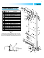
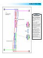
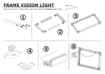
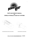
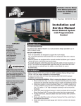
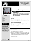
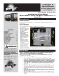
Parts & Service Manual
Power Gear H-point
Mini Hydraulic Slideout System
CONTENTS
Page
1217 E. 7th St.
Mishawaka, IN 46544
800-334-4712
Fax 574-256-6743
Preventive Maintenance
2
Manual Override
2
Parts
3
Wiring/Hydraulic Diagrams
6
Cable Routing
7
Troubleshooting/Warranty
8
www.powergearus.com
2
PREVENTIVE MAINTENANCE
WARNING
The hydraulic slide out system is
designed as a slide out system
only. Use of the hydraulic slide out
system for any other reason or
function could result in damage to
the coach and/or cause serious
injury or even death.
Your Power Gear slide-out system has been designed to require very little
maintenance. To ensure the long life of your slide-out system, read and
follow these few simple procedures:
Caution: Do not work on your slide out system unless the battery is
disconnected.
1. There is no requirement to change the Pentosyn
hydraulic fluid. Pentosyn® CHF-11S is also used as
a power steering fluid in the following automobiles:
Volkswagen, Mercedes, Audi, Peugeot, Saab,
Jaguar, and some models of Daimler-Chrysler.
Pentosyn® CHF-11S is recommended due to
excellent performance in extreme heat and cold. It
also has a long life and doesn’t thicken when the
RV is in storage
Check that potential parking
locations are clear of obstructions,
either permanent or temporary,
before operation.
Keep people clear of coach while
operating the slide out system.
Never expose hands or other parts
of the body near hydraulic leaks.
High pressure oil leaks may cut
and penetrate the skin causing
serious injury.
Fill Line
2. Check the fluid level periodically. Under normal usage, fluid should not
have to be added. Immediately investigate and correct any leaks, as the
system is designed to be leak-tight. Fluid level may be checked with room
in any position.
Park the coach on a reasonably
solid and level surface to optimize
the slide out system function.
3. Inspect and clean all hydraulic pump electrical connections every 12 months.
Read, study, and understand this
manual before operating the slide
out system.
4. Be sure that slide room is free of obstacles before attempting to open or
close the room.
MANUAL OVERRIDE
Your Power Gear slide system is equipped with a manual override that
allows you to retract the room in the event of a loss of power.
NOTE: If the room does not move when the switch is pressed, check the
following:
• Make sure the room slide system is turned on
• Battery is fully charged and connected
• If pump runs but room does not move, be sure that the
manual override valve on top of pump is closed (turn
clockwise until valve stops to close valve).
Counter-clockwise to
open valve
NOTE:
The room slide system cannot
be manually pushed out using
this method. It can only be
pushed in so the RV can be
taken to the nearest service
center.
After the previous items have been checked and the room still does not move when the room
slide switch is pressed, follow these simple steps to manually override your slide-out room.
1.
2.
3.
4.
5.
Turn ‘OFF’ the on/off switch.
Locate the room slide power unit
Locate manual override valve on top of pump block. Open the manual override valve by
turning it counter-clockwise with a flat blade screwdriver.
The room is now free to move. With the assistance of several people, push room in.
Tighten the manual override valve with a flat blade screwdriver. Take to your authorized
dealer for service.
3
PARTS
H-point extrusion (77.5”)
5
6
7
8
9
10
11
12
13
14
15
16
17
18
19
20
21
1-21
1-21
*
29
Qty
600251
600244
600242
130-1275
600293
600292
600286
180-1082
160-1070
600238
180-1079
160-1069
600276
150-1510
180-1078
600300
600301
150-1518
170-1026
170-1031
150-1517
15-1364
600289
600288
600273
130-1223
4
6
4
1
1
1
2
2
6
2
2
14
2
4
2
2
2
16
4
2
2
2
1
1
2
1
Description
Pulley assy. 1.375”
Pulley assy. 2.0”
Pulley assy. 1.75”
Cylinder assy 4pt 12” stroke
Extrusion, side RH
Extrusion, side LH
Bracket, outer pulley
Pin, pulley 3/8 x 1.25”
Washer, 3/8”
Bracket, pulley
Pin, pulley ½ x 2.125”
Washer, ½”
Block, cable adjustment
Set screw, ½ - 20 x 1.125”
Pin, pulley ½ x 1.3”
Bracket, cable retaining 2.0”
Bracket, cable retaining 1.84”
Rivet, pop ¼ x .25”
E-clip .5”
E-clip .375”
Screw FHSC, 5/16 - 24 x 1.0”
Nut jam ½ - 20
Assy, extrusion complete (77.5”) RH
Assy, extrusion complete (77.5”) LH
Extrusion cover, 77.5” (Not shown)
Mini-hydraulic pump, .5 liter capacity
*Part not shown
Note:
LH and RH refers to the extrusions from inside the coach, not the outside.
Only one extrusion shown. Other extrusion is mirror image. All parts are the
same for left or right hand extrusion unless specifically marked as LH or RH.
29
P
1
2
3
4
Part
Number
TO
Item
4
PARTS
5
8
H-point extrusion (75.75”)
2
1
8
2
2
5
P
TO
24
26
9
16
7
14
17
8
13
3
11
2
10
20
18
10
15
13
11
8
3
12
8
6
3
8
Note:
LH and RH refers to the extrusions from inside the coach, not the outside.
23
8
4
19
15
*Part not shown
**Part shown on page 6
15
Pulley assy. 1.375”
Pulley assy. 2.0”
Pulley assy. 1.75”
Pin, pulley 3/8 x 1.25”
Washer, .38”
Bracket, pulley
Pin, Pulley .5 x 2.725”
Washer, ½”
Block, cable adjustment
Set screw, ½ -20 x 1.175”
Pin, pulley ½ x 1.3”
Bracket, cable retaining 2”
Bracket, cable retaining 1.84”
Screw FHSC, 5/16 – 24 x 1.0”
E-clip .5”
E-clip .375”
¼ x .25 std pop rivet
Extrusion assembly, RH
Extrusion assembly, LH
Cylinder assy 4pt 12” stroke
Nut, jam ½ - 20
Bracket pulley weld, LH
Bracket pulley weld, RH
Plate spacer
Wear pad, 1 x .4 black
Nylock nut, UNC ¼-20
Screw FHSC, ¼-20 x 1 1/4
Extrusion assy complete LH
Extrusion assy complete RH
Extrusion cover
Mini-hydraulic pump, .5 liter capacity
Control harness
Wall switch
Relay control assy.
8
4
6
4
2
6
2
2
14
2
4
2
2
2
2
4
2
8
1
1
1
2
1
1
4
2
8
8
1
1
2
1
1
1
1
25
600251
600244
600242
180-1082
160-1070
600238
180-1087
160-1069
600276
150-1510
180-1078
600300
600301
150-1517
170-1026
170-1031
150-1518
600270
600269
130-1275
15-1364
600319
600320
600318
DN11879
15-1006
150-1525
600277
600278
600285
130-1223
14-1138
140-1197
521279
3
Description
22
Qty
8
19
20
21
22
23
24
25
26
1-26
1-26
*
29
**
**
**
Part
Number
6
18
12
1
2
3
4
5
6
7
8
9
10
11
12
13
14
15
16
17
8
15
Item
8
2
8
2
Only one extrusion shown. Other extrusion is mirror image. All parts are the
same for left or right hand extrusion unless specifically marked as LH or RH.
8
9
2
8
25
29
4
21
14
24
5
7
1
16
26
17
5
5
PARTS
28
26
24
12
24
12
26
28
26
41
28
Long cable runs
Note: Pictures on this page
are shown as reference only.
Refer to diagram on page 7 for
proper cable routing.
28
28
Short cable runs
12
24
28
26
12
24
28
Item
Part Number
Qty
*
*
*
080-1064
080-1083
080-1084
600298
600299
080-1079
080-1077
080-1080
080-1078
4
2
2
4
4
2
2
2
2
24
26
28
Description
Hose, 14 ft. (75.75” extrusion)
Hose, 3 ft. (77.5” extrusion)
Hose, 4 ft. (77.5” extrusion)
Bracket, cable attach LH
Bracket, cable attach RH
Cable, 50.0 in. (75.75” extrusion)
Cable, 51.5 in. (77.5” extrusion)
Cable, 119.0 in. (75.75” extrusion)
Cable, 120.5 in. (77.5” extrusion)
*Part not shown
H-point extrusion
cables & brackets
6
WIRING/HYDRAULIC DIAGRAMS
Mini Hydraulic wiring using Power Gear relay controller
*Available in kit:
521279
**Must be fused per
latest edition of
ANSI/RVIA standard
for low voltage
systems in
conversion and
recreational vehicles.
Note
These wiring diagrams represent
the different ways that the vehicle
manufacturer can wire the Power
Gear H-point Mini-Hydraulic slide
out system. Electrical components
represented here may or may not
be used on your system.
Power supply and wiring must be
capable of sustaining 10.5 volts
under maximum load.
System must be wired and fused
per latest edition of ANSI/RVIA
standard for low voltage systems
in conversion and recreational
vehicles.
Mini Hydraulic wiring using double pole, double throw
Hydraulic Diagram
Double pole,
double throw switch
*Must be fused per latest
edition of ANSI/RVIA
standard for low voltage
systems in conversion and
recreational vehicles.
The mini-hydraulic pump, hoses, and cylinders are pre-assembled and should not require bleeding after installation. If hoses are
disconnected from pump or cylinders at any point other than the quick-disconnect fittings, then the pump should be bled
following this procedure:
1.
2.
3.
Remove the fill plug on top of the mini-hydraulic reservoir
Cycle the cylinders to full extension and retraction 3 times, checking the fluid level inbetween cycles, and add
Pentosyn® CHF-11S power steering fluid only up to the center fill line (see page 2) of reservoir if necessary.
Replace the fill plug.
7
CABLE ROUTING
Note:
Dotted lines indicate
that the cable runs
behind pulley.
Note
This diagram is meant to
assist in the routing of the
cables should replacement
be necessary. This is not a
scale drawing, nor are the
actual cables color coded in
this way.
Room seal adjustment is
made at the cable
attachment block. Loosening
of the jamb nut combination
on the end of the cable will
allow for the corner of the
room that this cable pulls on
to be adjusted.
For example: If the lower
corner of the room is not
sealed as tight as the other
corners, identify that cable
and trace it back to the
cable attach block inside of
the min-hydraulic extrusion
(removal of the extrusion
cover will be necessary).
Loosen the jamb nut on that
cable and tighten the
adjustment nut (this should
draw that corner of the room
in).
8
TROUBLESHOOTING/WARRANTY
POWER GEAR
LIMITED WARRANTY
Power Gear warrants to the original retail
purchaser that the product will be free from
defects in material and workmanship for a period
of two (2) years following the retail sales date.
Power Gear will, at its option, repair or replace any
part covered by this limited warranty, which
following examination by Power Gear or its
authorized distributors or dealers, is found to be
defective under normal use and service. No
claims under this warranty will be valid unless
Power Gear or its authorized distributor or dealer
is notified in writing of such claim prior to the
expiration of the warranty period. Warranty is
transferable pending documentation of original
sale date of product.
THIS WARRANTY SHALL NOT APPLY TO:
•
Failure due to normal wear and tear,
accident, misuse, abuse, or negligence.
•
Products that are modified or altered in a
manner not authorized by Power Gear in
writing.
•
Failure due to misapplication of product.
•
Telephone or other communication expense
•
Living or travel expenses.
•
Overtime labor.
•
Failures created by improper installation of
the product’s slideout system or slideout
room to include final adjustments made at
the plant for proper room
extension/retraction; sealing interface
between slideout rooms and side walls;
synchronization of inner rails; or improper
wiring or ground problems.
•
Failures created by improper installation of
leveling systems, including final adjustments
made at the plant, or low fluid level, wiring or
ground problems.
•
Replacement of normal maintenance items.
There is no other express warranty other than the
foregoing warranty. THERE ARE NO IMPLIED
WARRANTIES OF MERCHANTIBILITY OR
FITNESS FOR A PARTICULAR PURPOSE. IN
NO EVENT SHALL POWER GEAR BE LIABLE
FOR ANY INCIDENTAL OR CONSEQUENTIAL
DAMAGES. This warranty gives you specific legal
rights, and you may also have other rights, which
vary from state to state. Some states do not allow
the limitations of implied warranties, or the
exclusion of incidental or consequential damages,
so the above limitations and exclusions may not
apply to you.
For service contact your nearest Power Gear
authorized warranty service facility or call 1-800334-4712. Warranty service can be performed
only by a Power Gear authorized service facility.
This warranty will not apply to service at any other
facility. At the time of requesting warranty service,
evidence of original purchase date must be
presented.
Power Gear
th
1217 E. 7 Street Mishawaka, IN 46544
800-334-4712
www.powergearus.com
Troubleshooting:
•
Pump is slow or lacks power
o Low Voltage- check for 10.5 volt minimum as pump
is running. Repair wiring or battery as necessary.
o Pinched hose- replace hose and bleed air out of
pump according to instructions on page 6.
•
Pump will not operate
o No Power-Check for minimum 10.5 volts to the pump
switch or relay battery + terminal.
o Bad switch-check for continuity between switch
center terminals and end terminals when switch is
operated.
o Faulty pump motor-Replace pump motor and bleed
air out of pump according to instructions on page 6.
o Bad pump- Replace pump and bleed air out of pump
according to instructions on page 6.
o Thermal overload protection in pump motor has
tripped. Allow motor to cool. Cool down time will vary
depending on ambient temperature and air flow to
pump.
•
Slide comes in misaligned
o Obstructions in slides path. Significant resistance
on one side may defeat the pressure compensation
built into the system. Repair whatever is obstructing
free movement of the slide. Move the slide to full
extension and full retraction to re-time the system.
o Pinched or obstructed hose- restriction in fluid
movement through a hose could potentially cause
misalignment. Make sure hoses are not linked,
abraded, or damaged from heat.
o Failure of the pressure compensation system
within the pump- Replace pump.