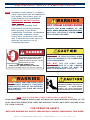
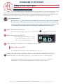
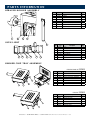
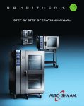
1
c o m b i t h e r M
G A S
®
Technical Service Manual
How to Use this Technical Service Manual
This manual has been compiled as a complete resource for a technician working on Combitherm Gas models. It includes
necessary product information and drawings, along with helpful troubleshooting procedures.
Introduction gives a quick overview of the Combitherm Gas line to aid in model identification.
Sections 1 through 5 contain information applying to Combitherm Gas models:
–CONTROL PANEL IDENTIFICATION includes information on using the controllers and operating instructions. It is
the same material supplied to the customer.
–PREVENTIVE MAINTENANCE includes procedures for cleaning. This information is also supplied to the customer.
–SERVICE MODE AND ERROR CODES explains the special programming available to you as a technician to view
status, make adjustments and test functions on models equipped with Standard and Deluxe Controllers. Information is
also included on the use of displayed error codes to resolve problems and on the functions that can be operated under
fault conditions.
–TROUBLESHOOTING TREES are provided for the most common conditions you will be required to address.
–COMBITHERM PARTS has drawings and lists of available parts that apply to the electric models.
Section 6 contains Wiring Diagrams that are specific to each model.
Printing
From this CD, you may print the Current Page or any range of pages. If you would like to print out a complete manual
for a specific model, print pages 1 – 102 (Sections 1 – 5) along with the pages in that model’s section (7.14 ESG, for
example). Here’s a tip: Because printers vary in their capacity to handle large drawings, make a test print of one of the
Wiring Diagrams before printing the model’s section.
C O M B I T H E R M G A S T ech n ica l S er v ice M a n u a l
T able of C ontents
How to Use this Technical Service Manual...................................... 2
Introduction.................................................................................. 4
1 — Control Panel Identification.................................................. 5
2 — Preventive Maintenance....................................................... 49
3 — Service Mode and Error Codes............................................. 63
4 — Troubleshooting Trees......................................................... 5 — Combitherm Parts............................................................... 6 — Wiring Diagrams................................................................. 115
CC
OO
MM
BB
I TI T
HH
EE
RR
MMEG
LE
AC
S TTRech
IC n
Tica
echlnS
ica
erlv ice
S erM
v ice
a n uM
a la n•u3
al
I ntroduction
MODEL NUMBERS
This manual covers the following gas models:
Boiler-Free Models
6.10ESG
10.10ESG
7.14ESG
12.18ESG
10.20ESG
20.20ESG
CONTROLLERS
•Standard is a touch key controller.
•Deluxe is a touch key controller with programmable Rapid-Touch™ keys.
•S-Control is rotary dial controller.
FEATURES AND OPTIONS
•Recessed Door is available on all models.
•Smoker Mode is available on boiler-free gas models.
•Core Temp Probe (single point) is optional on S-control models.
MODES
The Combitherm combination oven/steamer is a multipurpose oven used for:
STEAM MODE
COMBINATION MODE
CONVECTION MODE
RETHERM MODE
CORE TEMPERATURE MODE
CC
OO
MM
BB
I TI T
HH
EE
RR
MMEG
LE
AC
S TTRech
IC n
Tica
echlnS
ica
erlv ice
S erM
v ice
a n uM
a la n•u4
al
1
C O N T R O L PA N E L I D E N T I F I C AT I O N
Standard and Deluxe Control .........................................................
6
S-Control .....................................................................................
45
Return to Main Table of Contents ..................................................
3
S E C T I O N 1 – C O N T R O L PA N E L I D E N T I F I C AT I O N • COMBITHERM GAS TECHNICAL SERVICE MANUAL • 5
C O N T R O L PA N E L I D E N T I F I C AT I O N
STANDARD AND PROGRAMMABLE DELUXE MODELS
POWER ON/OFF KEY
STEAM MODE KEY
RETHERM MODE KEY
CONVECTION MODE KEY
PROGRAM INSTALL/EDIT KEY
START / STOP KEY
COMBINATION MODE KEY
PROGRAMMED MENU KEY
DELUXE MODELS ONLY
CHEF FUNCTION KEY
DELUXE MODELS ONLY
FUNCTION & OPERATING
INDICATORS
COOKING TEMPERATURE KEY
TIME KEY
DOWN ARROW KEY
CONTROL PANEL DISPLAY
CORE TEMPERATURE KEY
UP ARROW KEY
RAPID-TOUCH KEYS
ADJUSTMENT KNOB
DELUXE MODELS ONLY
MOISTURE VENT KEY
ELECTRIC MODELS ONLY
S E C T I O N 1 – C O N T R O L PA N E L I D E N T I F I C AT I O N • COMBITHERM GAS TECHNICAL SERVICE MANUAL • 6
S TA N D A R D & D E L U X E C O N T R O L PA N E L B A S I C F U N C T I O N
POWER ON/OFF KEY
DOWN ARROW KEY
Used to decrease displayed cook temperature
Activates power to the oven.
, time , or core temperature and as a
scrolling key for programming functions.
STEAM MODE KEY
The oven will operate in the steam mode at a
temperature range of 86°F to 248°F
Displays oven functions. Serves the same
(30°C to 120°C).
function as the up and down arrow keys to
• Automatic steaming at 212°F (100°C)
increase or decrease the displayed cook
FACTORY - SET DEFAULT .
temperature , time , or core temperature .
• Quick steaming between 213°F and 248°F
(101°C and 120°C).
• Low Temperature Steaming between
RETHERM MODE KEY
Food rethermalization or reheating mode will
Stops an activated cooking mode or
operate with automatic steam injection at a
programmed procedure currently in progress,
temperature range of 248°F to 320°F
and exits the Chef function key .
(120°C to 160°C).
COMBINATION MODE KEY
CONVECTION MODE KEY
Selection key for cooking with a combination
Selection key for convection cooking without
of steam and convection heat that can be set
steam at a temperature range of 86°F to 482°F
within a temperature range of 212°F to 482°F
(30°C to 250°C).
PROGRAM INSTALL AND EDIT KEY
PROGRAMMED MENU KEY
Used to create, change, duplicate, and delete
Used to access and exit a menu list of all
programmed menus.
stored cooking programs that can be reviewed
in display .
mode or in the Combination mode .
programmed procedures stored in memory.
(100°C to 250°C).
oven compartment while cooking in the Convection
START/STOP KEY
Initiates all cooking mode functions and
MOISTURE VENT KEY
Immediately vents steam and condensate from the
86°F and 211°F (30°C and 99°C).
ADJUSTMENT KNOB
DELUXE MODELS ONLY
CHEF FUNCTION KEY
• • • • • • •CONTROL
DELUXE MODELS ONLY .
PANEL DISPLAY
CORE TEMPERATURE KEY
Used to set the required internal product
Used to select programmed menu functions,
temperature, to recall the internal product
various auxiliary functions, and several chef
temperature set by the operator, or to display
help instructions.
the current internal temperature of the product
in conjunction with the down arrow key , the
COOKING TEMPERATURE KEY
up arrow key , or the adjustment knob .
Used to set the required cooking temperature,
to recall the set cooking temperature, or to
check the actual oven temperature in
conjunction with the down arrow key , the
up arrow key or the adjustment knob .
TIME KEY
UP ARROW KEY
Used to increase displayed cook temperature
, time , or core temperature and as a
scrolling key for programming functions.
• • • • • • •RAPID-TOUCH
KEYS
DELUXE MODELS ONLY.
Used to set the required cooking time or recall
One-touch cooking for immediate access to
the set cooking time in conjunction with the
frequently used operator set programs including
down arrow key , the up arrow key , or
cooking modes, cleaning, and other oven functions.
the adjustment knob .
S E C T I O N 1 – C O N T R O L PA N E L I D E N T I F I C AT I O N • COMBITHERM GAS TECHNICAL SERVICE MANUAL • 7
CONTINUED
S TA N D A R D & D E L U X E C O N T R O L PA N E L B A S I C F U N C T I O N S
FUNCTION & OPERATING INDICATORS
A.
GOLD-N-BROWN FEATURE
This indicator will illuminate when the browning function is set by the operator in a
timed or programmed cooking cycle in either convection mode or combination mode.
B.
COMBI SMOKER (ON
EQUIPPED MODELS)
This indicator will illuminate when the smoking function is set by the operator in a
timer, probe or programmed cooking cycle in either convection mode or combination
mode.
C.
REDUCED FAN SPEED
This indicator will illuminate whenever the operator sets a reduced fan speed to
protect products affected by high-velocity air movement.
D.
CONFIRMATION OF OVEN OPERATION
This indicator illuminates whenever the oven is operating in any mode.
E.
KEY LOCK
This indicator will illuminate when operator has locked any mode key or function to
prevent unauthorized or accidental changes.
F.
MOISTURE VENT
This indicator will illuminate whenever the Moisture Vent Key is pressed by the operator to eliminate excessive moisture.
G.
ENERGY LOCK
FOR USE WITH OVENS INSTALLED UNDER AN ALTO-SHAAM VENTLESS HOOD.
This indicator is a safety feature that will illuminate and prevent the oven from being
operated unless the ventless oven hood is operating.
S E C T I O N 1 – C O N T R O L PA N E L I D E N T I F I C AT I O N • COMBITHERM GAS TECHNICAL SERVICE MANUAL • 8
SET-UP PROCEDURES
SET UP MENU
Following installation, the control should be set with the date and time. In addition to the date and time,
the set-up function provides the operator with the ability to adjust a number of other Combither m
operating conditions to confor m with the needs of the individual installation.
PRESS THE ON/OFF POWER KEY
TO THE ON POSITION.
SET UP ADJUSTMENT CHOICES
PRESS THE CHEF FUNCTION KEY.
SIGNAL TONE
Rotate the adjustment knob
until the set up symbol is
VOLUME
highlighted within the display.
TIME
PRESS THE CHEF FUNCTION KEY.
Press the up and down arrow keys
or rotate the adjustment knob to select
DATE
“ YES ” for the set up function.
PROGRAM INDEX
Set up
DEFAULT/MEMO SETTINGS
TEMPERATURE DISPLAY
PRESS THE CHEF FUNCTION KEY TO
CONFIRM THE SET UP FUNCTION.
NETWORK ADDRESS
Press the up and down arrow keys
or rotate the adjustment knob to
highlight one of the following
LANGUAGE
adjustment functions:
SIGNAL TONE
Rotate the adjustment knob until the signal tone symbol
is highlighted within the display.
PRESS THE CHEF FUNCTION KEY TO CONFIRM THE SIGNAL TONE SELECTION.
Press the up and down arrow keys or rotate the adjustment knob to select each tone offered.
Stop rotation at each individual setting to hear an audio playback. Select the tone desired.
PRESS THE CHEF FUNCTION KEY TO CONFIRM THE SELECTED SIGNAL TONE SETTING.
S E C T I O N 1 – C O N T R O L PA N E L I D E N T I F I C AT I O N • COMBITHERM GAS TECHNICAL SERVICE MANUAL • 9
SET-UP PROCEDURES
A L W AY S B E G I N S E T U P A D J U S T M E N T S F R O M T H E S E T U P M E N U
.
VOLUME
Rotate the adjustment knob until the volume symbol
is highlighted within the display.
PRESS THE CHEF FUNCTION KEY TO CONFIRM THE VOLUME SELECTION.
Press the up and down arrow keys or rotate the adjustment knob to select each volume level
offered. Stop rotation at each individual setting to hear an audio playback. Select the volume
desired with consideration of the noise level within the kitchen during peak production periods.
PRESS THE CHEF FUNCTION KEY TO CONFIRM THE VOLUME SETTING.
TIME
Rotate the adjustment knob until the time symbol
is highlighted within the display.
PRESS THE CHEF FUNCTION KEY TO CONFIRM THE TIME SELECTION.
Press the up and down arrow keys to alternate between hours and minutes and rotate the
adjustment knob in each to adjust the numbers to the correct time.
PRESS THE CHEF FUNCTION KEY TO CONFIRM THE SET TIME.
D AT E
Rotate the adjustment knob until the date symbol
is highlighted within the display.
PRESS THE CHEF FUNCTION KEY TO CONFIRM THE DATE SELECTION.
Rotate the adjustment knob to select the preferred date format.
Press the up and down arrow keys to alternate between day, month and year, and rotate the
adjustment knob in each to adjust the numbers to the correct settings.
PRESS THE CHEF FUNCTION KEY TO CONFIRM THE SET DATE.
PROGRAM INDEX
Rotate the adjustment knob until the program index symbol
is highlighted within the display.
PRESS THE CHEF FUNCTION KEY TO CONFIRM THE PROGRAM INDEX SELECTION.
Press the up and down arrow keys or rotate the adjustment knob to select the preferred index format:
“YES” for a listing of programs entered alphabetically with the program install/edit key.
“NO” for a listing of programs entered numerically with the program install/edit key.
PRESS THE CHEF FUNCTION KEY TO CONFIRM THE PROGRAM INDEX SETTING.
S E C T I O N 1 – C O N T R O L PA N E L I D E N T I F I C AT I O N • COMBITHERM GAS TECHNICAL SERVICE MANUAL • 10
SET-UP PROCEDURES
A L W AY S B E G I N S E T U P A D J U S T M E N T S F R O M T H E S E T U P M E N U
.
D E FA U LT / M E M O S E T T I N G
The default/memo setting allows the operator to choose
between a display showing the factory set defaults for
time and temperature or the last operator set values for
time and temperature in each cooking mode. This
adjustment function also allows the operator to change
the defaults from those set at the factory to settings that
better meet the needs of the individual operation.
Cooking product with operator set defaults for time and
temperature can help reduce operator error. Cooking
with the oven in the memo setting is particularly useful
when several batches are cooked in succession. The
memo setting eliminates the necessity to set time and
temperature for each batch.
Rotate the adjustment knob until the default/memo symbol
is highlighted within the display.
PRESS THE CHEF FUNCTION KEY TO CONFIRM THE DEFAULT/MEMO SELECTION.
Rotate the adjustment knob to “NO” for memo. This setting will display the last operator set values for
time and temperature in each cooking mode.
PRESS THE CHEF FUNCTION KEY TO CONFIRM THE MEMO SETTING.
TO CHANGE THE DEFAULT SETTINGS
Rotate the adjustment knob to select “YES”.
A numbered list of default descriptions will appear in the display. Rotate the adjustment knob
until the setting to be changed is highlighted. Press the up arrow key to highlight the time or
temperature to be changed. Rotate the adjustment knob to change the default to the setting
desired. Press the down arrow key to save the new default setting.
PRESS THE CHEF FUNCTION KEY TO CONFIRM THE NEW DEFAULT SETTINGS.
COMBITHERM FACTORY SET DEFAULT SETTINGS
COOKING
MODE
OVEN
TEMPERATURE
CORE
TEMPERATURE
STEAM
212°F
158°F
MODE
(100°C)
(70°C)
COMBINATION
302°F
158°F
STEAM MODE
(150°C)
(70°C)
CONVECTION
MODE
RETHERM
MODE
338°F
158°F
(170°C)
(70°C)
275°F
158°F
(135°C)
(70°C)
DELTA-T
122°F
172°F
MODE
(50°C)
(77°C)
374°F
FREE
PREHEAT
MODE
COOKING
TIME
25 MINUTES
70 MINUTES
30 MINUTES
5 MINUTES
FREE
—
(140°C)
S E C T I O N 1 – C O N T R O L PA N E L I D E N T I F I C AT I O N • COMBITHERM GAS TECHNICAL SERVICE MANUAL • 11
SET-UP PROCEDURES
A L W AY S B E G I N S E T U P A D J U S T M E N T S F R O M T H E S E T U P M E N U
.
T E M P E R AT U R E D I S P L AY
Rotate the adjustment knob until the temperature display symbol
is highlighted within the display.
PRESS THE CHEF FUNCTION KEY TO CONFIRM THE TEMPERATURE DISPLAY SELECTION.
Press the up and down arrow keys or rotate the
adjustment knob to select either Fahrenheit or Celsius.
PRESS THE CHEF FUNCTION KEY TO CONFIRM THE TEMPERATURE DISPLAY SETTING.
NETWORK ADDRESS
Press the up and down arrow keys or rotate the adjustment knob until the network address
symbol
is highlighted within the display.
PRESS THE CHEF FUNCTION KEY TO CONFIRM THE NETWORK ADDRESS SELECTION.
The current network address will appear in the display.
Rotate the adjustment knob to select 1 through 99 and assign
a different network number for each PC to be connected.
PRESS THE CHEF FUNCTION KEY TO CONFIRM EACH NETWORK ADDRESS.
LANGUAGE
Press the up and down arrow keys or rotate the adjustment knob
until the language symbol
is highlighted within the display.
PRESS THE CHEF FUNCTION KEY TO CONFIRM THE LANGUAGE PROGRAM SELECTION.
Rotate the adjustment knob to select the required language.
CHINESE
DUTCH
ENGLISH*
FRENCH
GERMAN
*U.S.
ITALIAN
JAPANESE
KOREAN
POLISH
PORTUGUESE
RUSSIAN
SPANISH
SWEDISH
FACTORY SETTING
NOTE : SOME OF THE LANGUAGE SELECTIONS SHOWN ABOVE MAY NOT BE AVAILABLE ON ALL MODELS .
PRESS THE CHEF FUNCTION KEY TO CONFIRM THE LANGUAGE SETTING.
S E C T I O N 1 – C O N T R O L PA N E L I D E N T I F I C AT I O N • COMBITHERM GAS TECHNICAL SERVICE MANUAL • 12
I M P O R TA N T S A F E T Y P R E C A U T I O N S
NOTE: Automatic steam venting is a standard
safety feature built into all Combitherm
oven models. This feature vents all
steam from the oven compartment
IMMEDIATELY BEFORE COOKING
TIME EXPIRES.
This function is provided in all
programmed and timed production
when operating in any Steam,
Combination, Convection, and Retherm
cooking mode. Automatic steam
venting does not function if the oven
door is opened before time expires or
when the oven has been set to
continuous operation.
AT NO TIME SHOULD THE INTERIOR OR
EXTERIOR BE STEAM CLEANED, HOSED
DOWN, OR FLOODED WITH WATER OR
LIQUID SOLUTION OF ANY KIND. DO NOT
USE WATER JET TO CLEAN.
SEVERE DAMAGE OR
E L E C T R I C A L H A Z A R D C O U L D R E S U LT.
WARRANTY BECOMES VOID IF APPLIANCE IS FLOODED.
DO NOT HANDLE PANS CONTAINING LIQUID
OR SEMILIQUID PRODUCTS POSITIONED
ABOVE THE EYE LEVEL OF THE OPERATOR.
SUCH PRODUCTS CAN SCALD AND CAUSE
SERIOUS INJURY.
HOT STEAM CAUSES BURNS
ROTATE THE DOOR HANDLE TO THE
FIRST OPEN ROTATION POSITION ONLY.
WAIT UNTIL THE STEAM IS VENTED BEFORE
FULLY OPENING THE DOOR.
D O N O T USE THE ATTACHED HANDHELD HOSE TO SPRAY ANYTHING OTHER
THAN THE INTERIOR OF THE COMBITHERM
OVEN COMPARTMENT.
DO
N O T U S E T H E S P R AY H O S E
ON THE SURFACE OF A HOT COOKING
COMPARTMENT. ALLOW THE OVEN TO
COOL TO A MINIMUM OF 150°F (66°C).
METAL PARTS OF THIS EQUIPMENT
BECOME EXTREMELY HOT WHEN IN
OPERATION.
TO AVOID BURNS,
ALWAYS USE HAND PROTECTION
WHEN OPERATING THIS APPLIANCE.
NOTE: U S E A U T H O R I Z E D C O M B I T H E R M O V E N C L E A N E R O N LY.
UNAUTHORIZED CLEANING AGENTS MAY DISCOLOR OR HARM INTERIOR SURFACES OF THE
OVEN. READ AND UNDERSTAND LABEL AND M AT E R I A L S A F E T Y D ATA S H E E T B E F O R E U S I N G
THE OVEN CLEANER.
FOR OPERATOR SAFETY
NOTE AND OBSERVE ALL SAFETY PRECAUTIONS LOCATED THROUGHOUT THIS GUIDE.
S E C T I O N 1 – C O N T R O L PA N E L I D E N T I F I C AT I O N • COMBITHERM GAS TECHNICAL SERVICE MANUAL • 13
STEAM MODE
STEAM G LOW TEMPERATURE STEAM G QUICK STEAM
The Steam mode provides the operator with the ability to steam, poach, or blanch.
This mode will automatically steam at the boiling point of water; quick-steam above the
boiling point for faster cooking results; or low temperature steam, below the boiling point,
for more delicate products such as pâté, mousse, seafood, or custard.
PRESS THE ON/OFF POWER KEY TO THE ON POSITION.
PRESS THE STEAM MODE KEY.
Automatic Steam temperature of 212°F (100°C) will appear in the display.
The last set time or oven control default setting for time will appear in the display.
PRESS THE START KEY TO STEAM AT THE SETTINGS SHOWN.
TO CHANGE THE SETTINGS SHOWN:
PRESS THE TEMPERATURE KEY.
The cooking temperature will appear highlighted within the oven display.
Press the up and down arrow keys or rotate the adjustment knob to select
the desired cooking temperature.
• Automatic Steaming 212°F (100°C)
• Quick-steaming 213°F to 248°F (101°C to 120°C)
• Low Temperature Steaming 86°F to 211°F (30°C to 99°C)
TO COOK BY TIME:
PRESS THE TIME KEY.
The cooking time will appear highlighted within the oven display.
Press the up and down arrow keys or rotate the adjustment knob to
select the time desired…
or
Set control for continuous operation by rotating the adjustment knob to the right until
appears in the display.
TO COOK BY INTERNAL PRODUCT TEMPERATURE:
PRESS THE CORE TEMP KEY.
The previously set core temperature or oven control default setting will appear
highlighted within the oven display.
Press the up and down arrow keys or rotate the adjustment knob to
select the internal temperature desired and insert the product probe.
PRESS THE START KEY TO BEGIN COOKING IN THE STEAM MODE.
• The set cooking temperature will appear in the display. To adjust the set temperature, press the
key
once and make corrections as required. To display the actual oven temperature, press the
key twice.
• The remaining cooking time will appear in the display. To display the set time or to change the set
values for time during operation, press the time key
once and make corrections as required.
• The actual internal product temperature will appear in the display. To display the set internal product
temperature or to change the set values for core temperature during operation, press the
key once
and make corrections as required.
When the cooking time has expired or the operator set internal temperature has been reached, a buzzer
will sound indicating the end of the operating mode.
• To stop the buzzer, press the start/stop key
or open the oven door.
S E C T I O N 1 – C O N T R O L PA N E L I D E N T I F I C AT I O N • COMBITHERM GAS TECHNICAL SERVICE MANUAL • 14
STEAM MODE
C H E F O P E R AT I N G T I P S
This mode will steam a full or partial load of a single product, or multiple products
without transfer of flavors. When steaming multiple products, however, individual
product cooking times must be taken into consideration. The non-pressurized
atmosphere of the Combitherm also provides the ability to open the door during the
steam mode in order to monitor products more closely throughout the steaming process.
STEAM
QUICK STEAMING
LOW TEMP STEAM
Perforated, 2-1/2" deep pans
Quick steaming is suitable
The low temperature steam mode
(65mm) are particularly suitable
for hearty, root-type vegetables
will function whenever the oven
for use in this program mode.
such as potatoes, legumes,
compartment temperature is
These pans will provide a shorter
and cabbage.
below 212°F (100°C).
product over-cooking at the
Quick steaming provides a
Proof yeast dough at a
bottom of the pan.
cooking time which is
temperature setting of 90°F to
approximately 10-percent shorter
110°F (32°C to 43°C).
cooking time and will prevent
Separate ice-encased vegetables
than the regular steam mode
before steaming to assure more
temperature of 212°F (100°C).
It will take longer to steam
products using the low
even cooking.
Set the steam cooking
temperature steam mode.
A variety of products can be
temperature between 221°F
steamed at the same time but
(105°C) and 230°F (110°C) for
Steaming sausages in low
attention must be paid to the
small loads and between 230°F
temperature steam prevents
different cooking times required
(110°C) and 248°F (120°C) for
cracked or peeling skins.
for each food product.
full loads.
Use low temperature steam for
Butter and season vegetables
delicate foods such as shrimp,
after steaming.
fish, seafood, and crème caramel.
Steam long-grain rice using
For best results, low temperature
approximately 1-part rice to
steam all delicate food items at a
approximately 1-1/2-parts water
temperature of 210°F (99°C)
or seasoned liquid.
or below.
Steam durum wheat noodles in
unperforated pans using 1-part
noodles to 5-parts cold water.
S E C T I O N 1 – C O N T R O L PA N E L I D E N T I F I C AT I O N • COMBITHERM GAS TECHNICAL SERVICE MANUAL • 15
C O M B I N AT I O N M O D E
The Combination mode will prove to be the most versatile and widely used mode
the Combitherm oven has to offer. It will produce the best possible results on the
widest variety of products — all within the shortest period of time. The unique control
function of this mode enables the operator to roast or bake with a combination of
steam and convection heat. In addition to shorter cooking times, this combination of
steam and heat offers less product shrinkage and more moisture retention than obtained
in a standard convection oven.
PRESS THE ON/OFF POWER KEY TO THE ON POSITION.
PRESS THE COMBINATION MODE KEY.
The last set values or oven control default setting for temperature will appear in the display.
The last set time or oven control default setting for time will appear in the display.
PRESS THE START KEY TO COOK AT THE SETTINGS SHOWN.
TO CHANGE THE SETTINGS SHOWN:
PRESS THE TEMPERATURE KEY.
The cooking temperature will appear highlighted within the oven display.
Press the up and down arrow keys or rotate the adjustment knob to
select the desired cooking temperature.
• 212°F to 482°F (100°C to 250°C)
TO COOK BY TIME:
PRESS THE TIME KEY.
The cooking time will appear highlighted within the oven display.
P ress the up and down arrow keys or rotate the adjustment knob to select
the time desired…
or
Set control for continuous operation by rotating the adjustment knob to the right until
appears in the display.
TO COOK BY INTERNAL PRODUCT TEMPERATURE:
PRESS THE CORE TEMP KEY.
The core temperature will appear highlighted within the oven display.
Press the up and down arrow keys or rotate the adjustment knob to
select the internal temperature desired and insert the product probe.
PRESS THE START KEY TO BEGIN COOKING IN THE COMBINATION MODE.
• The set cooking temperature will appear in the display. To adjust the set temperature, press the
once and make corrections as required. To display the actual oven temperature, press the
key
key twice.
• The remaining cooking time will appear in the display. To display the set time or to change the set
values for time during operation, press the time key
once and make corrections as required.
• The actual internal product temperature will appear in the display. To display the set internal
product temperature or to change the set values for core temperature during operation, press the
key once and make corrections as required.
When the cooking time has expired or the operator set internal temperature has been reached, a
buzzer will sound indicating the end of the operating mode.
• To stop the buzzer, press the start/stop key
or open the oven door.
S E C T I O N 1 – C O N T R O L PA N E L I D E N T I F I C AT I O N • COMBITHERM GAS TECHNICAL SERVICE MANUAL • 16
COMBINATION MODE
CHEF OPERATING TIPS
Th e C o m b i n a t i o n m o d e i n j e c t s t h e o p t i m u m a m o u n t o f s t e a m
automatically. There is no need to select moisture levels. Foods do not
dry out. Flavors are retained with no transfer of flavors when mixing
product loads.
Due to the automatic steam adjustment, the
door can be opened at any time during a
cooking operation. Be certain to observe the
safety war ning when opening the oven door.
The Combination mode is particularly efficient
when used for baking, broiling, grilling, stewing,
braising, and roasting.
When using the Combination mode, cooking
temperatures can be reduced 10- to 20-percent
below the temperatures used for conventional
cooking methods.
Cooking time will be reduced approximately
40-percent when cooking at the same temperature
used for convection oven cooking and up to 50- to
60-percent less time when cooking at the same
temperature used for a conventional oven.
Food browning in the Combither m begins
at a cooking temperature of approximately
248°F (120°C).
A higher cooking temperature results in heavier
browning but also results in greater product
weight loss. To achieve additional browning use
the Moisture Vent Key or set Gold-n-Brown into
the product procedure. Gold-n-Brown is
particularly useful for adding color to high moisture
products such as chicken and other poultry items
or for additional browning of full loads and other
moist products.
The Combination mode provides even browning
without the necessity to tur n the pans.
For more even cooking, do not cook in pans
deeper than 4-inches (100mm).
S E C T I O N 1 – C O N T R O L PA N E L I D E N T I F I C AT I O N • COMBITHERM GAS TECHNICAL SERVICE MANUAL • 17
CONVECTION MODE
The Convection mode operates with hot circulated air within a temperature range
of 86° to 482°F (30° to 250°C). For many applications, better results may be
achieved with the Combination mode; therefore, the operator may want to consider
using the Convection mode on a more limited basis.
PRESS THE ON/OFF POWER KEY TO THE ON POSITION.
PRESS THE CONVECTION MODE KEY.
The last set values or oven control default setting for temperature will appear in the display.
The last set time or oven control default setting for time will appear in the display.
PRESS THE START KEY TO COOK AT THE SETTINGS SHOWN.
TO CHANGE THE SETTINGS SHOWN:
PRESS THE TEMPERATURE KEY.
The cooking temperature will appear highlighted within the oven display.
Press the up and down arrow keys or rotate the adjustment knob
to select the desired cooking temperature.
• 86° to 482°F (30° to 250°C)
TO COOK BY TIME:
PRESS THE TIME KEY.
The cooking time will appear highlighted within the oven display.
Press the up and down arrow keys or rotate the adjustment knob to select the
time desired…
or
Set control for continuous operation by rotating the adjustment knob to the right until
appears in the display.
TO COOK BY INTERNAL PRODUCT TEMPERATURE:
PRESS THE CORE TEMP KEY.
The core temperature will appear highlighted within the oven display.
Press the up and down arrow keys or rotate the adjustment knob to
select the internal temperature desired and insert the product probe.
PRESS THE START KEY TO BEGIN THE COOKING MODE.
• The set cooking temperature will appear in the display. To adjust the set temperature, press the
once and make corrections as required. To display the actual oven temperature, press the
key
key twice.
• The remaining cooking time will appear in the display. To display the set time or to change the set
values for time during operation, press the time key
once and make corrections as required.
• The actual internal product temperature will appear in the display. To display the set internal product
temperature or to change the set values for core temperature during operation, press the
key once
and make corrections as required.
When the cooking time has expired or the operator set internal temperature has been reached, a buzzer
will sound indicating the end of the operating mode.
• To stop the buzzer, press the start/stop key
or open the oven door.
To check the length of time the product has been operating in the core temperature mode, press and hold the
time key
along with the core temperature key
. The time period will appear at the top of the display.
S E C T I O N 1 – C O N T R O L PA N E L I D E N T I F I C AT I O N • COMBITHERM GAS TECHNICAL SERVICE MANUAL • 18
CONVECTION MODE
CHEF OPERATING TIPS
The Convection Mode can be used to roast or bake products needing very
short cooking times or for high moisture products such as muffins, cakes,
and cookies, or for browning the sur face of the product.
The Convection mode works best with foods
containing little moisture or for very moist food
which require a dryer finished product.
For baking, preheat the Combither m at a
temperature of 36°F to 54°F (20°C to 30°C) above
the baking temperature required. Once preheated,
reset the temperature as required.
A higher cooking temperature results in heavier
browning but also results in greater product weight
loss. To achieve additional browning use the
Moisture Vent Key or set the Browning Feature
into the product procedure.
To prevent the sur face of food from excessive
drying, the fan will not engage if the inter nal
oven temperature is above 212°F (100°C)
and the set oven temperature is below
212°F (100°C).
S E C T I O N 1 – C O N T R O L PA N E L I D E N T I F I C AT I O N • COMBITHERM GAS TECHNICAL SERVICE MANUAL • 19
RETHERM MODE
The Retherm mode can be used to rethermalize (regenerate) portioned food on
plates, trays, or platters within a short period of time. Steam is automatically injected
into the oven compartment as required. Items are brought up to proper serving
temperatures without dry edges or condensate forming on the plates.
PRESS THE ON/OFF POWER KEY TO THE ON POSITION.
PRESS THE RETHERM MODE KEY.
The last set values or the default settings will appear in the display.
PRESS THE START KEY TO COOK AT THE SETTINGS SHOWN.
TO CHANGE THE SETTINGS SHOWN:
PRESS THE TEMPERATURE KEY.
The cooking temperature will appear highlighted within the oven display.
Press the up and down arrow keys or rotate the adjustment knob
to select the desired cooking temperature.
• 248° to 320°F (120° to 180°C)
TO COOK BY TIME:
PRESS THE TIME KEY.
The cooking time will appear highlighted within the oven display.
P ress the up and down arrow keys or rotate the adjustment knob to select the
time desired…
or
Set control for continuous operation by rotating the adjustment knob to the
right until
appears in the display.
TO COOK BY INTERNAL PRODUCT TEMPERATURE:
PRESS THE CORE TEMP KEY.
The core temperature will appear highlighted within the oven display.
Press the up and down arrow keys or rotate the adjustment knob to
select the internal temperature desired and insert the product probe.
PRESS THE START KEY TO BEGIN THE RETHERM MODE.
• The set cooking temperature will appear in the display. To adjust the set temperature, press the
key
once and make corrections as required. To display the actual oven temperature, press the
key twice.
• The remaining cooking time will appear in the display. To display the set time or to change the set
values for time during operation, press the time key
once and make corrections as required.
• The actual internal product temperature will appear in the display. To display the set internal product
temperature or to change the set values for core temperature during operation, press the
key once
and make corrections as required.
When the cooking time has expired or the operator set internal temperature has been reached, a buzzer
will sound indicating the end of the operating mode.
• To stop the buzzer, press the start/stop key
or open the oven door.
To check the length of time the product has been operating in the core temperature mode, press and hold the
time key
along with the core temperature key
. The time period will appear at the top of the display.
S E C T I O N 1 – C O N T R O L PA N E L I D E N T I F I C AT I O N • COMBITHERM GAS TECHNICAL SERVICE MANUAL • 20
RETHERM MODE CHEF OPERATING TIPS
Since plated meals consist of dissimilar products, there are several important factors
to consider in order to produce the finest results. Product density (compactness),
thickness, quantity of product on each plate, and quantity of plates all relate to the
length of time necessary to reheat. Again, experience is the best method to
determine reheating time. Once the time has been determined and recorded for a
specific meal, the results will be consistent for future reheating times.
HELPFUL HINTS FOR REHEATING ON THE PLATE
• ALL FOOD COMPONENTS ON THE PLATE SHOULD BE OF SIMILAR DENSITIES.
• ALL FOOD COMPONENTS ON THE PLATE SHOULD BE SIMILAR IN THICKNESS.
• ARRANGE ALL FOOD COMPONENTS EVENLY ON THE PLATE.
• AVOID EXCESSIVE OVERLAPPING OF PRODUCT.
• SAUCES MUST BE HEATED AND ADDED TO PRODUCT AFTER REHEATING.
• A MIXED VARIETY OF MEALS CAN BE REHEATED AT THE SAME TIME.
• À LA CARTE RETHERMALIZATION
required. Follow internal temperature requirements
À la carte rethermalization is designed to take
a single plate from a refrigerated temperature to
serving temperature for immediate service. Plates
are prepared in advance, covered, and refrigerated.
Preheat the Combitherm oven. Remove plate from
refrigeration and place in the oven at 275°F (135°C)
for an uncovered plate or 300°F (150°C) for a
covered plate. Plates with meat components will
take more time than plates containing all vegetable
components. Follow internal temperature
requirements for reheating and allow for override
time. After reheating, remove the plate from the
oven, add any sauces, garnish, and serve. This
process can be repeated as required.
for reheating and allow for override time. Remove
For the most efficient continuous service, it is
suggested that the Combitherm oven be dedicated to
the rethermalization process during serving hours.
• BANQUET RETHERMALIZATION
Banquet rethermalization is designed for high
volume, full or partial load (multiple plate) reheating.
For maximum efficiency, it is essential that volume
rethermalization be used in conjunction with the
utilization of holding cabinets to keep rethermalized
food at proper temperatures.
Plates are assembled in advance, covered, and
refrigerated or loaded on the roll-in cart and
refrigerated. Preheat the Combitherm oven at
275°F (135°C) for uncovered plates or 300°F (150°C)
for covered plates. Remove plates or the roll-in cart
from refrigeration, load in the oven and set timer as
the plates or roll-in cart from the Combitherm and
roll into the companion holding cabinet. Relocate
the holding cabinet to the banquet service area.
• RETHERMALIZING PREFABRICATED AND
VACUUM-PACKED FROZEN FOODS
For bulk product rethermalization, completely
defrost product bags in walk-in cooler. DO NOT
REMOVE PRODUCT FROM THE BAG. Load
thawed bags in preheated oven and rethermalize in
the Low Temperature Steam mode until the required
internal temperature is reached. Place rethermalized
bags in a preheated holding cabinet set at
140° to 165°F (60° to 74°C) until ready for service.
For large volume on-the-plate regeneration,
defrost bags in walk-in cooler. Open bags and plate
per menu requirements in a ( MAXIMUM ) 55°F (13°C)
refrigerated room. Cover plates, place on Alto-Shaam
roll-in cart (trolley), and roll into Combitherm oven
preheated at 275°F (135°C).
Regenerate in the Convection mode for 3 to 5
minutes. Switch to the Retherm mode for an
additional 3 minutes or more if required. Transfer
full trolley to a preheated holding cabinet set at
160°F (71°C) until ready for service. In the case of
meat cooked to rare, set the cabinet at 140°F (60°C).
PLATE COVERS MUST BE USED FOR ON-THE-PLATE REGENERATION.
S E C T I O N 1 – C O N T R O L PA N E L I D E N T I F I C AT I O N • COMBITHERM GAS TECHNICAL SERVICE MANUAL • 21
C O R E T E M P E R AT U R E P R O B E M O D E
A s a n a l t e r n a t i v e t o t i m e r o p e r a t i o n , t h e C o r e Te m p e r a t u r e P r o b e m o d e c a n
be used in conjunction with any program mode to cook by sensing internal
product temperature. For a more accurate internal temperature, a
specialized Combitherm product probe senses temperature from four strategic
points and displays a temperature average.
PRESS THE ON/OFF POWER KEY TO THE ON POSITION.
INSERT THE PRODUCT PROBE.
The probe must be inserted so that the tip is positioned in the center of the food mass.
For liquid or semiliquid foods, suspend the probe in the center of the product and
secure the probe wire to the container edge.
SELECT AND PRESS THE REQUIRED COOKING PROGRAM.
PRESS THE TEMPERATURE KEY.
The cooking temperature will appear highlighted within the oven display.
Press the up and down arrow keys or rotate the adjustment knob to
select the desired cooking temperature within the temperature range of
the cooking mode selected.
PRESS THE CORE TEMP KEY.
The core temperature will appear highlighted within the oven display.
Press the up and down arrow keys or rotate the adjustment knob to
select the internal product cutoff temperature.
PRESS THE START KEY TO BEGIN THE COOKING MODE.
• The actual internal product temperature will appear in the display. To display the set internal product
temperature or to change the set values for core temperature during operation, press the
key once
and make corrections as required.
When the operator set internal temperature has been reached, a buzzer will sound indicating the end of
the operating mode.
• To stop the buzzer, press the start/stop key
or open the oven door.
To check the length of time the product has been operating in the core temperature mode, press and hold the
time key
along with the core temperature key
. The time period will appear at the top of the display.
CHEF OPERATING TIPS
To pr event over-cooking, r emove pr oduct fr om the oven as soon as the r equir ed inter nal
temperatur e is r eached in either the Cor e Temperatur e mode or the Cor e Temperatur e Delta-T
mode. The Cor e Temperatur e mode should not be used for cooking thin pr oduct items.
DO NOT USE THE PROBE WHEN COOKING THIN PRODUCTS.
S E C T I O N 1 – C O N T R O L PA N E L I D E N T I F I C AT I O N • COMBITHERM GAS TECHNICAL SERVICE MANUAL • 22
DELTA-T CORE TEMPERATURE COOKING
This special program function cooks by internal product temperature with the use of
the probe. Unlike the standard core temperature mode, however, the Delta-T oven
temperature automatically increases in direct proportion to the internal temperature
of the product. The Delta-T mode cooks with convection heat but provides a more
gentle method of cooking. Browning occurs toward the end of the cooking cycle.
PRESS THE ON/OFF POWER KEY TO THE ON POSITION.
PRESS THE CHEF FUNCTION KEY.
Press the up and down arrow keys or rotate the adjustment knob until the
Delta-T
symbol is highlighted in the display.
PRESS THE CHEF FUNCTION KEY.
Delta-T
Press the up and down arrow keys or rotate the
adjustment knob to select “ YES ” for the Delta-T function.
PRESS THE CHEF FUNCTION KEY TO CONFIRM THE SETTING.
PRESS THE TEMPERATURE KEY.
Press the up and down arrow keys or rotate the adjustment knob to select the desired
Delta-T cooking temperature within the cooking temperature ranges shown below.
PRESS THE CORE TEMP KEY.
Press the up and down arrow keys or rotate the adjustment knob to select the
internal product cutoff temperature within the temperature ranges shown below.
PRODUCT
DELTA-T TEMPERATURE
CORE TEMPERATURE SETTING
BEEF ROAST
122°F to 131°F (50°C to 55°C)
118°F to 136°F (48°C to 58°C)
TENDERLOIN
122°F to 140°F (50°C to 60°C)
122°F to 140°F (50°C to 60°C)
VEAL & LAMB
122°F to 158°F (50°C to 70°C)
172°F (78°C)
PORK ROAST
122°F to 158°F (50°C to 70°C)
172°F (78°C)
HAM
122°F to 140°F (50°C to 60°C)
172°F (78°C)
COOKING MODE.
THE OVEN WILL BEGIN THE DELTA-T CONVECTION
The set Delta-T temperature will appear in the display.
The actual internal product temperature will appear in the display.
When the operator set internal temperature has been reached, a buzzer will sound indicating
the end of the operating mode.
• To stop the buzzer, press the start/stop key
or open the oven door.
DIFFERENCE BETWEEN COOKING COMPARTMENT TEMPERATURE
AND INTERNAL PRODUCT TEMPERATURE.
COOKING
COMPARTMENT
TEMPERATURE
INTERNAL
PRODUCT
TEMPERATURE
PRODUCT AND OVEN
TEMPERATURE START
INTERNAL PRODUCT
TEMPERATURE REACHED
S E C T I O N 1 – C O N T R O L PA N E L I D E N T I F I C AT I O N • COMBITHERM GAS TECHNICAL SERVICE MANUAL • 23
AUXILIARY FUNCTIONS
CHEF FUNCTION KEY
There are several auxiliary functions available through the use of the Chef Function Key.
With the exception of the ability to add additional moisture to the oven compartment, that
can only be used during the convection mode, all additional functions can be engaged at any time during any
cooking mode. Chef Functions can also be programmed into a cooking procedure in oven models that
include the deluxe programmable feature. At the end of a cooking mode or program, the oven automatically
disengages all operator-set chef functions. These functions, however, do remain programmed and will
reengage the next time the programmed procedure is used.
P R E H E AT I N G
THE PREHEATING FUNCTION IS ENGAGED IN THE CONVECTION
MODE AT A FIXED
TEMPERATURE AND TIME. BOTH THE TEMPERATURE AND TIME CAN BE ADJUSTED BY THE
OPERATOR TO COMPLY WITH THE REQUIREMENTS OF THE INDIVIDUAL OPERATION.
SEE START UP PROCEDURES UNDER DEFAULT/MEMO SETTING
.
PRESS THE CHEF FUNCTION KEY.
Rotate the adjustment knob until the preheat symbol
is highlighted in the display.
PRESS THE CHEF FUNCTION KEY.
Press the up and down arrow keys
Preheating
or rotate the adjustment knob to select
“ YES ” for the Preheat function.
PRESS THE CHEF FUNCTION KEY TO CONFIRM THE SETTING.
THE OVEN WILL BEGIN THE PREHEAT FUNCTION.
• The set preheat temperature will appear in the display.
• The set preheat time will appear in the display.
• The preheat symbol
will appear in the display.
When the set time and temperature has been reached, a buzzer will sound indicating
the end of the preheat function.
• To stop the buzzer, press the start/stop key
or open the oven door.
S E C T I O N 1 – C O N T R O L PA N E L I D E N T I F I C AT I O N • COMBITHERM GAS TECHNICAL SERVICE MANUAL • 24
AUXILIARY FUNCTIONS
CHEF FUNCTION KEY
GOLD-N-BROWN
The browning feature is an automatic function designed to regulate humidity for additional color
to products as needed. This feature is particularly useful for adding color to high moisture
products such as chicken and other poultry items or for additional browning of full loads and
other moist products. In addition, this feature may be used to add texture to fried items such as
French fries or breaded chicken. Gold-n-Brown can be used in both the combination mode and
the convection mode and can be programmed into a cooking procedure.
Browning can be used for any product with a set cooking time more than 5-minutes. Depending
on the type of product and product load, the browning feature may also slightly increase the set
cooking time in order to fully complete the browning function. This is a standard operating
condition of this feature.
SELECT AND PRESS THE REQUIRED COOKING MODE AND SET MODE FUNCTIONS.
PRESS THE CHEF FUNCTION KEY.
Rotate the adjustment knob until the browning symbol
is highlighted within
the display.
PRESS THE CHEF FUNCTION KEY.
Brown
Press the up and down arrow keys or rotate the
adjustment knob to select “ YES ” for the browning function.
PRESS THE CHEF FUNCTION KEY TO CONFIRM THE SETTING.
The browning indicator light
will illuminate directly above the display.
PRESS THE START KEY.
The oven will engage the browning feature in the Combination or Convection mode set
by the operator.
S E C T I O N 1 – C O N T R O L PA N E L I D E N T I F I C AT I O N • COMBITHERM GAS TECHNICAL SERVICE MANUAL • 25
AUXILIARY FUNCTIONS
CHEF FUNCTION KEY
C O O L - D O W N F E AT U R E
The cool-down feature provides the operator with the ability to lower the temperature of the
oven compartment at an accelerated pace. This function is useful when it is necessary to immediately
change from a high temperature cooking function to a lower temperature function or to the steam program.
This function is also useful to help cool the oven compartment in preparation for cleaning.
CHEF OPERATING TIP
When using the cool-down feature in preparation for cleaning, it is important to remember
the temperature in the display indicates the air temperature inside the oven compartment
and not the interior walls of the oven. Always make certain to allow the oven walls to cool
to a minimum of 140°F (60°C) before spraying the compartment with oven cleaner.
PRESS THE CHEF FUNCTION KEY.
Rotate the adjustment knob until the cool-down symbol
is highlighted in the display.
PRESS THE CHEF FUNCTION KEY.
Press the up and down arrow keys
Cool Down
or rotate the adjustment knob to select
“ YES ” for the cool-down function.
PRESS THE CHEF FUNCTION KEY TO CONFIRM THE SETTING.
OPEN THE OVEN DOOR.
The display will indicate the current temperature of the oven.
ROTATE THE ADJUSTMENT KNOB TO SELECT A COOL-DOWN TEMPERATURE WITHIN A
RANGE OF 212°F TO 68°F (100°C TO 20°C).
THE FACTORY SET DEFAULT IS
122°F (50°C).
The displayed temperature will continue to decline until it reaches the operator set
temperature or factory default temperature if not selected by the operator.
S E C T I O N 1 – C O N T R O L PA N E L I D E N T I F I C AT I O N • COMBITHERM GAS TECHNICAL SERVICE MANUAL • 26
AUXILIARY FUNCTIONS
CHEF FUNCTION KEY
R E D U C E D FA N S P E E D
The reduced fan speed function is useful for flow-sensitive products such as soufflês and
meringues, or any products affected by a high velocity of air movement.
SELECT AND PRESS THE REQUIRED COOKING MODE AND SET MODE FUNCTIONS.
PRESS THE CHEF FUNCTION KEY.
Rotate the adjustment knob until the fan symbol
is highlighted in the display.
PRESS THE CHEF FUNCTION KEY.
Press the up and down arrow keys or rotate
Redcʼd fan speed
t h e a d j u s t m e n t k n o b t o s e l e c t “ YES ” f o r t h e r e d u c e d
fan speed function.
PRESS THE CHEF FUNCTION KEY TO CONFIRM THE SETTING.
The reduced fan speed indicator light
will illuminate directly above the display.
PRESS THE START KEY.
The oven will start at a reduced fan speed in whatever cooking mode set by the operator.
REDUCED POWER
ELECTRIC MODELS ONLY
The reduced power function can be used to reduce kitchen power peaks and energy consumption.
SELECT AND PRESS THE REQUIRED COOKING MODE AND SET MODE FUNCTIONS.
PRESS THE CHEF FUNCTION KEY.
Rotate the adjustment knob until the reduced power symbol
is highlighted
in the display.
PRESS THE CHEF FUNCTION KEY.
Press the up and down arrow keys or rotate
Redcʼd power
t h e a d j u s t m e n t k n o b t o s e l e c t “ YES ” f o r t h e r e d u c e d
power function.
PRESS THE CHEF FUNCTION KEY TO CONFIRM THE SETTING.
PRESS THE START KEY.
The oven will operate with reduced power in whatever cooking mode set by the operator.
REDUCED POWER WILL RESULT IN LONGER COOKING TIMES.
S E C T I O N 1 – C O N T R O L PA N E L I D E N T I F I C AT I O N • COMBITHERM GAS TECHNICAL SERVICE MANUAL • 27
AUXILIARY FUNCTIONS
CHEF FUNCTION KEY
OPERATING ELEMENTS THAT
CANNOT BE LOCKED
KEY LOCK
Except as noted, all of the mode keys and
functions available on the Combitherm can be
locked to prevent unauthorized or accidental
changes to the settings.
PRESS THE CHEF FUNCTION KEY.
Rotate the adjustment knob until the key symbol
is highlighted within the display.
PRESS THE CHEF FUNCTION KEY.
Press the up and down arrow keys or rotate the
Key lock
adjustment knob to select “ YES ” for the key lock function.
PRESS THE CHEF FUNCTION KEY TO CONFIRM THE SETTING.
The display will indicate PIN 000.
ROTATE THE ADJUSTMENT KNOB TO PIN 000.
¶ PIN 000 is the factory set default to prevent an accidental lock or unlock of the control functions.
PRESS THE CHEF FUNCTION KEY.
THE DISPLAY WILL INDICATE “ALL KEYS UNLOCKED.”
SELECT AND PRESS THE FIRST
CONTROL FUNCTION TO BE LOCKED.
The display will indicate “LOCK.”
If the wrong key has been selected and locked in error, press the same control key again and
“UNLOCK” will appear in the display.
Continue in this manner until all desired control functions are locked.
PRESS THE START KEY TO CONFIRM THE LOCKING FUNCTION.
Whenever any control function has been locked, the key lock symbol will be illuminated within the display.
Whenever any locked control function is pressed, the key lock symbol will flash and an
audible signal will sound.
KEY UNLOCK
FOLLOW THE SAME PROCEDURE AS ABOVE UNTIL THE DISPLAY INDICATES “ALL KEYS UNLOCKED.”
To u n l o c k t h e C h e f F u n c t i o n
key.
PRESS THE POWER KEY TO TURN THE OVEN OFF.
PRESS THE CHEF FUNCTION KEY
ROTATE THE ADJUSTMENT KNOB TO PIN 000 TO DISENGAGE ALL LOCK FUNCTIONS.
PRESS THE CHEF FUNCTION KEY. THE DISPLAY WILL INDICATE “ALL KEYS UNLOCKED.”
S E C T I O N 1 – C O N T R O L PA N E L I D E N T I F I C AT I O N • COMBITHERM GAS TECHNICAL SERVICE MANUAL • 28
AUXILIARY FUNCTIONS
CHEF FUNCTION KEY
STEAM INJECTION
Additional steam can be added to the cooking compartment at any time when cooking in the
convection mode.
PRESS THE CHEF FUNCTION KEY.
Rotate the adjustment knob until the steam injection symbol
is highlighted within
the display.
PRESS THE CHEF FUNCTION KEY.
Press the up and down arrow keys or rotate
Add moisture
the adjustment knob to select “ YES ” for the steam
injection function.
PRESS THE CHEF FUNCTION KEY TO ACTIVATE THE STEAM INJECTION FUNCTION.
Additional steam is injected into the oven compartment for a time period of
approximately 15 seconds.
NOTE: Steam injection cannot be programmed through the control keypad, but can
be programmed through optional Kitchen Management software.
S E C T I O N 1 – C O N T R O L PA N E L I D E N T I F I C AT I O N • COMBITHERM GAS TECHNICAL SERVICE MANUAL • 29
AUXILIARY FUNCTIONS
GENERAL SMOKER OPERATION
SMOKING FUNCTION
ON EQUIPPED MODELS
LOAD WOOD CHIPS.
G Measure one container full of dry wood chips.
G
Soak dry chips in water for 5 minutes.
G
Shake excess water off wood chips.
G
Place moistened chips back into the container
and position the container securely on the two prongs
located on the interior back panel of the oven.
A full container of wood chips will produce smoke
for an approximate period of one to two hours
depending on the cooking temperature being used
for the selected product. The tested procedures in
this manual for many of the products that are appropriate
for smoking provide complete product smoke penetration
and full smoke flavor.
AVAILABLE FROM ALTO-SHAAM
WOOD CHIPS
20 POUND BULK PACKS
THE TOTAL WEIGHT OF WOOD CHIP
BULK PACKS MAY VARY DUE TO HIGH
MOISTURE CONTENT WHEN PACKAGED.
HICKORY
APPLE
CHERRY
SUGAR MAPLE
WC-22543
WC-2829
WC-22541
WC-22545
CHEF OPERATING TIP
Pr oducts such as ribs that r equir e heavier smoke penetration to r each full smoke flavor
should r emain in the oven after cooking has been completed. Do not open the oven door.
Set the oven in the Low Temperatur e Steam Mode at 140° to 160°F (60° to 71°C) and allow
the pr oduct to r emain in the oven for a period of one hour.
If you would like assistance, you are invited to contact an Alto-Shaam corporate chef for recommendations.
NOTE: Always keep the OVEN DOOR CLOSED whenever operating the smoking function.
The Combitherm Smoker can be operated without using the smoking function. After using the oven as a
smoker, however, it is necessary to clean the oven in order to prevent a transfer of smoke flavor to nonsmoked products. Cleaning instructions are provided in this manual.
D O N O T OPEN THE OVEN DOOR DURING
THE SMOKING FUNCTION. The introduction
of outside air in the oven compartment may
cause the wood chips to flame.
THE USE OF IMPROPER MATERIALS FOR THE
SMOKING FUNCTION COULD RESULT IN DAMAGE,
HAZARD, EQUIPMENT FAILURE, OR COULD
REDUCE THE OVERALL LIFE OF THE OVEN.
DO NOT USE SAWDUST FOR SMOKING.
DO NOT USE WOOD CHIPS SMALLER THAN
THUMBNAIL SIZE.
S E C T I O N 1 – C O N T R O L PA N E L I D E N T I F I C AT I O N • COMBITHERM GAS TECHNICAL SERVICE MANUAL • 30
AUXILIARY FUNCTIONS
CHEF FUNCTION KEY
S M O K E R F E AT U R E
ON EQUIPPED MODELS
U. S . PAT.
7,157,668
The ability to smoke product, hot or cold, is offered on all boiler-free electric models and on all
gas models with the exception of the 10•20ES GAS , the 12•18ES GAS , and the 20•20ES GAS . The
smoking function can be engaged in either the Combination mode or the Convection mode of
operation. The smoking function cannot be operated when the oven is operating in the steam
mode or the retherm mode.
SELECT AND PRESS THE REQUIRED COOKING MODE (CONVECTION OR COMBINATION).
TO SET COOK TEMPERATURE:
PRESS THE TEMPERATURE KEY.
The cooking temperature will appear highlighted within the oven display.
Press the up and down arrow keys or rotate the adjustment knob to select the desired
cooking temperature.
TO SET COOK TIME:
PRESS THE TIME KEY.
The cooking time will appear highlighted within the oven display.
Press the up and down arrow keys or rotate the adjustment knob to select the time
desired.
or
Set control for continuous operation by rotating the adjustment knob to the right until desired
time appears in the display.
TO ACTIVATE SMOKER:
PRESS THE CHEF FUNCTION KEY.
Rotate the adjustment knob until the smoker symbol
within the display.
is highlighted
PRESS THE CHEF FUNCTION KEY.
Press the up and down arrow keys or rotate the
Smoker
adjustment knob to select “ YES ” for the Smoker function.
PRESS THE CHEF FUNCTION KEY TO CONFIRM
THE SETTING.
PRESS THE START KEY TO ACTIVATE THE SMOKER FUNCTION.
METAL PARTS OF THIS EQUIPMENT
BECOME EXTREMELY HOT WHEN IN
OPERATION.
TO AVOID BURNS,
ALWAYS USE HAND PROTECTION
WHEN OPERATING THIS APPLIANCE.
S E C T I O N 1 – C O N T R O L PA N E L I D E N T I F I C AT I O N • COMBITHERM GAS TECHNICAL SERVICE MANUAL • 31
AUXILIARY FUNCTIONS
CHEF FUNCTION KEY
ENERGY LOCK
F O R U S E W I T H O V E N S I N S TA L L E D U N D E R A V E N T L E S S H O O D .
Energy lock is a safety feature to prevent the oven control from being operated unless the ventless
oven hood is in operation. The energy lock indicator light will illuminate in the control display if this
situation occurs and the oven control will be inoperable until the oven hood is reset and operating.
PRESS THE CHEF FUNCTION KEY.
Rotate the adjustment knob until the energy lock symbol
is highlighted within the
display.
PRESS THE CHEF FUNCTION KEY.
Energy Lock
Press the up and down arrow keys or rotate
the adjustment knob to select “ YES ” for the energy
lock function.
PRESS THE CHEF FUNCTION KEY TO ACTIVATE THE ENERGY LOCK FUNCTION.
The oven control will not operate when power is engaged until the ventless hood
is reset and operating.
Press the “Combi Reset” button on the ventless hood to energize the hood and
return the oven control to normal operation.
ENERGY PROTECTION
FURNISHED UPON REQUEST AS A FACTORY INSTALLED OPTION
In locations where the electric service is regulated with a device installed on site, this function will
protect full power to the Combitherm for the duration of the next operator set program or cooking mode.
This function cannot be set during an active cooking mode or program. Power interruption may affect all
other electric service within the regulated location.
F O R U S E O N LY I N T H O S E C O U N T R I E S W H E R E T H E L O C A L E L E C T R I C
U T I L I T Y P R O V I D E S A N E N E R G Y O P T I M I Z AT I O N S Y S T E M I N S TA L L E D O N S I T E .
PRESS THE CHEF FUNCTION KEY.
Rotate the adjustment knob until the program protection symbol
is highlighted
within the display.
PRESS THE CHEF FUNCTION KEY.
Press the up and down arrow keys or rotate
Program protection
the adjustment knob to select “ YES ” for the energy
protection function.
PRESS THE CHEF FUNCTION KEY TO ACTIVATE THE PROGRAM PROTECTION FUNCTION.
S E C T I O N 1 – C O N T R O L PA N E L I D E N T I F I C AT I O N • COMBITHERM GAS TECHNICAL SERVICE MANUAL • 32
A D VA N C E F E AT U R E S
MOISTURE VENT KEY
This function provides the operator with the ability to eliminate excessive moisture from
the oven compartment and the exterior surface of the foods being cooked. The moisture
vent key is designed to operate in both the Combination mode and in the Convection
cooking mode. On deluxe models, this function can also be made part of a cooking program.
PRESS THE MOISTURE VENT KEY TO REDUCE STEAM AND MOISTURE LEVELS IN THE OVEN.
The illuminated, blue portion of the Moisture Vent Key will go out. Open vent
within the display.
symbol will illuminate
PRESS THE MOISTURE VENT KEY TO DISENGAGE THE MOISTURE VENT KEY FUNCTION.
The blue portion of the Moisture Vent Key will illuminate. Open vent
will extinguish.
symbol within the display
AT THE END OF A COOKING MODE, THE MOISTURE VENT KEY WILL AUTOMATICALLY DISENGAGE.
S E C T I O N 1 – C O N T R O L PA N E L I D E N T I F I C AT I O N • COMBITHERM GAS TECHNICAL SERVICE MANUAL • 33
A D VA N C E F E AT U R E S
QUICK PROGRAMMING
This quick programming function provides the operator with the ability to temporarily program a cooking
procedure using multiple cooking modes, along with any auxiliary functions desired. Quick programming is
particularly useful when cooking several batches of the same product back-to-back and will remain
programmed until any new cooking mode key is pressed.
PRESS AND HOLD THE FIRST REQUIRED COOKING MODE FOR A PERIOD OF 3-SECONDS.
01/01 will appear at the top of the display indicating STEP ONE.
The temperature and time will appear directly below 01/01.
PRESS THE TEMPERATURE KEY.
The temperature will become highlighted within the display.
ROTATE THE ADJUSTMENT KNOB TO SELECT THE REQUIRED TEMPERATURE.
PRESS THE TIME KEY OR THE CORE TEMP KEY
.
The time or core temperature will become highlighted within the display.
ROTATE THE ADJUSTMENT KNOB TO SELECT THE REQUIRED SETTING.
PRESS AND HOLD THE SECOND REQUIRED COOKING MODE FOR A PERIOD OF 3-SECONDS.
Follow the above directions until all steps have been entered.
PRESS THE START KEY.
The oven will begin cooking as programmed, automatically switching to each cooking
mode entered. Each step entered will be indicated in the display as the oven cycles from
mode to mode. E X A M P L E : 0 1 / 0 5 = S T E P O N E O F F I V E
02/05 = STEP TWO OF FIVE
PRESS THE STOP KEY OR OPEN THE OVEN DOOR WHEN THE BUZZER SOUNDS AT THE END
OF THE PROGRAM.
THIS PROGRAM WILL REMAIN IN TEMPORARY MEMORY UNTIL ANY NEW
COOKING MODE KEY IS PRESSED. QUICK PROGRAMMING CAN BE SAVED AND
STORED IN MEMORY ON DELUXE MODELS ONLY.
S E C T I O N 1 – C O N T R O L PA N E L I D E N T I F I C AT I O N • COMBITHERM GAS TECHNICAL SERVICE MANUAL • 34
A D VA N C E F E AT U R E S
Auxiliary Functions are made part of the control as an additional convenience to the operator, however,
these functions are not necessary for the general operation of the Combitherm oven.
START TIME PRESELECT
Start time preselect provides the operator with the ability
to program a fixed start time for oven operation. This
function can be operated when cooking in any mode and
is offered as a convenience to set an advanced start-up of
the preheating function prior to the beginning of the
production day. It can also be used for advance start-up
for non-refrigerated items such as baked potatoes.
To prevent food spoilage, this feature
is not recommended for use with any
raw product that requires temperature
maintenance at or under 40°F (4°C).
SELECT AND PRESS THE REQUIRED COOKING MODE.
Set all mode functions such as temperature, time, core temperature, etc.
The time entered in the initial operational mode setup will automatically be
reflected on the start time preselect display.
PRESS AND HOLD THE TIME KEY WHILE TURNING THE ADJUSTMENT KNOB.
The display will indicate the current programmed settings in 24-hour (military) time.
A.M.
01:00
00:48
OVEN START
IN 48 MINUTES
10:23 11:23
STARTING TIME
10:23 A.M.
ENDING TIME
11:23 A.M.
1-HOUR TOTAL
COOKING TIME
P.M.
1:00
1:00
1:00 13:00
2:00
2:00
2:00 14:00
3:00
3:00
3:00 15:00
4:00
4:00
4:00 16:00
5:00
5:00
5:00 17:00
6:00
6:00
6:00 18:00
7:00
7:00
7:00 19:00
8:00
8:00
8:00 20:00
9:00
9:00
9:00 21:00
10:00 10:00 10:00 22:00
11:00 11:00 11:00 23:00
12:00 12:00 12:00 24:00
The cooking time shown ( UPPER RIGHT ) indicates automatic oven operation for a period of one hour and
appears only when cooking by time as entered in the initial operational mode setup.
TO CHANGE THE STARTING TIME, PRESS AND HOLD THE TIME KEY AND TURN THE
ADJUSTMENT KNOB.
Rotate the adjustment knob to select the starting time desired. As the starting time is
changed, the countdown for oven start ( LEFT ) and the ending time will automatically
adjust accordingly.
RELEASE THE TIME KEY AFTER THE REQUIRED STARTING TIME HAS BEEN SELECTED.
The oven preselect start time display will immediately begin a countdown and will
automatically start the oven when zero is reached.
THIS FUNCTION CAN BE CANCELLED AT ANY TIME BY PRESSING THE START/STOP KEY
S E C T I O N 1 – C O N T R O L PA N E L I D E N T I F I C AT I O N • COMBITHERM GAS TECHNICAL SERVICE MANUAL • 35
.
PROGRAM FUNCTION
COMBITHERM PROGRAMMING SYMBOLS
RECORD
COPY PROCEDURE
INSERT STEP
SAVE
DELETE PROCEDURE
APPEND STEP
NEW PROCEDURE
EDIT PROCEDURE
DELETE STEP
RECORDING A COOKING PROCEDURE
Recording a cooking procedure provides the operator with the ability to test and
verify all set operating parameters for the selected cooking modes and to make any
necessary adjustments before saving and storing the procedure into memory.
PRESS THE PROGRAM INSTALL AND EDIT KEY.
Press the up and down arrow keys or ro t a t e t h e a d j u s t m e n t
knob until the record symbol
is highlighted in the display.
PRESS THE PROGRAM INSTALL KEY TO CONFIRM THE SELECTION.
The display will indicate “Recorder ON” and the record symbol
will appear in the display.
SELECT AND PRESS THE FIRST REQUIRED COOKING MODE.
Set all cooking mode parameters for temperature, time, or internal product temperature
plus auxiliary functions, and advanced features for the first step to be recorded.
PRESS THE START KEY TO BEGIN THE FIRST RECORDED STEP.
When the cooking time has expired or the operator set internal temperature has been reached, a buzzer will
sound indicating the end of the operating mode.
• To stop the buzzer, press the start/stop key
or open the oven door.
SELECT AND PRESS THE SECOND REQUIRED COOKING MODE.
Set all cooking mode parameters for temperature, time, or internal product temperature
plus auxiliary functions, and advanced features for the second step to be recorded.
PRESS THE START KEY TO BEGIN THE SECOND RECORDED STEP.
Continue to record cooking modes as indicated for up to 20 steps.
All cooking mode steps entered with “Recorder ON” will remain in memory, in the order entered, until the recorder is
turned off. Recorded procedures will not be lost or affected by pressing the stop/start key
.
S E C T I O N 1 – C O N T R O L PA N E L I D E N T I F I C AT I O N • COMBITHERM GAS TECHNICAL SERVICE MANUAL • 36
PROGRAM FUNCTION
TO CANCEL THE RECORDING FUNCTION
WITH THE “Recorder ON” FUNCTION ACTIVATED, PRESS THE PROGRAM INSTALL AND EDIT KEY.
Press the up and down arrow keys or r o t a t e t h e a d j u s t m e n t k n o b u n t i l t h e r e c o r d
symbol
is highlighted in the display.
PRESS THE PROGRAM INSTALL KEY TO CONFIRM THE SELECTION.
“Recorder OFF” will appear in the display and the oven can be operated normally.
S AV I N G A R E C O R D E D C O O K I N G P R O C E D U R E
When the previous cooking mode steps recorded produce satisfactory results, the recorded
cooking procedure can be saved in memory for future use.
PRESS THE PROGRAM INSTALL/EDIT KEY.
Press the up and down arrow keys or rotate the
adjustment knob until the save symbol
is highlighted in the display.
PRESS THE PROGRAM INSTALL/EDIT KEY TO CONFIRM THE SELECTION.
Name the procedure. Rotate the adjustment knob to select the first letter
of the procedure name. Press the up and down arrow key to select
second letter position and rotate the adjustment knob to select the second
A
—
—
—————
letter. Continue this procedure for each subsequent alpha character,
number, or symbol required.
PRESS THE PROGRAM INSTALL AND EDIT KEY TO CONFIRM THE PROCEDURE NAME.
The display will indicate the first unoccupied memory location within the programmed menu.
If an alternate location is desired, rotate the adjustment knob to highlight another unoccupied,
numbered memory location within the programmed menu. If an occupied location is selected,
the existing procedure will be replaced by the new procedure.
PRESS THE PROGRAM INSTALL/EDIT KEY TO CONFIRM THE PROCEDURE LOCATION.
The display will indicate “please wait” and will return to the main menu display.
The procedure has now been saved in the selected location and can be verified by rotating the
adjustment knob to the saved procedure.
To review the set operating parameters of any programmed procedure, press the programmed menu
key
and rotate the adjustment knob until the procedure to be reviewed is highlighted in the display. Press the chef
function
key. The cooking mode key for the first step will illuminate and the program mode, temperature,
time, or core temperature will appear in the display. Rotate the adjustment knob to review each step.
S E C T I O N 1 – C O N T R O L PA N E L I D E N T I F I C AT I O N • COMBITHERM GAS TECHNICAL SERVICE MANUAL • 37
PROGRAM FUNCTION
C R E AT I N G A N E W C O O K I N G P R O C E D U R E
Cooking procedures for items prepared on a regular basis can be stored in memory.
PRESS THE PROGRAM INSTALL/EDIT KEY.
Press the up and down arrow keys or rotate the adjustment knob until the new procedure
symbol
is highlighted in the display.
PRESS THE PROGRAM INSTALL/EDIT KEY TO CONFIRM THE SELECTION.
All cooking mode keys will begin to flash and 01/01 will appear at the top of the
display indicating the first cooking step.
SELECT AND PRESS THE FIRST REQUIRED COOKING MODE.
Set cooking mode functions for temperature and time, or internal core temperature. Add any auxiliary functions
along with the moisture venting feature. Follow the basic operating instructions located in this booklet. Auxiliary
functions can be added by pressing the chef function
key after entering the operating mode parameters for
each individual step and pressing the up and down arrow keys or rotating the adjustment knob to select the
auxiliary function required. Press the chef function key to confirm the auxiliary function setting(s) for each step.
PRESS THE PROGRAM INSTALL/EDIT KEY TO CONFIRM THE FIRST STEP.
SELECT AND PRESS THE SECOND REQUIRED COOKING MODE.
The display will indicate 02/02 indicating the second cooking mode step.
Set all cooking mode functions as indicated above.
PRESS THE PROGRAM INSTALL/EDIT KEY TO CONFIRM THE SECOND STEP.
CONTINUE WITH THE ABOVE INSTRUCTIONS UNTIL ALL MODE STEPS AND FUNCTIONS ARE ENTERED.
UP TO 20 COOKING MODE STEPS CAN BE SAVED IN A SINGLE PROCEDURE.
AFTER ALL FUNCTIONS ARE ENTERED,
PRESS THE PROGRAM INSTALL/EDIT KEY TO CONFIRM THE NEW PROCEDURE.
Name the procedure. Rotate the adjustment knob to select
the first letter of the procedure name. Press the up and
down arrow key to select second letter position and rotate
t h e a d j u s t m e n t k n o b t o s e l e c t t h e s e c o n d l e t t e r. C o n t i n u e f o r
e a c h s u b s e q u e n t a l p h a c h a r a c t e r, n u m b e r, o r s y m b o l r e q u i r e d .
A
—
—
—————
PRESS THE PROGRAM INSTALL AND EDIT KEY TO CONFIRM THE PROCEDURE NAME.
Rotate the adjustment knob to highlight an unoccupied, numbered memory location within the
programmed menu. If an occupied location is selected, the existing procedure will be
replaced by the new procedure.
PRESS THE PROGRAM INSTALL AND EDIT KEY TO CONFIRM THE PROGRAM INSTALLATION.
The display will indicate “please wait” and will return to the main menu display.
S E C T I O N 1 – C O N T R O L PA N E L I D E N T I F I C AT I O N • COMBITHERM GAS TECHNICAL SERVICE MANUAL • 38
PROGRAM FUNCTION
S TA R T A P R O G R A M M E D P R O C E D U R E
PRESS THE PROGRAMMED MENU KEY.
All stored procedures are listed alphabetically or numerically as selected by the
operator in the initial oven start up procedures under the program index category.
Rotate the adjustment knob until the required procedure is highlighted in the display.
PRESS THE START KEY.
To
review
the
set
pr ogrammed menu
parameters
of
any
programmed
procedure,
press
the
key and r otate the adjustment knob until the pr ocedur e to
be r eviewed is highlighted in the display. Pr ess the chef function
key. The
cooking mode, temperatur e, time, or cor e temperatur e will appear in the display.
COPY A PROGRAMMED PROCEDURE
PRESS THE PROGRAMMED MENU KEY.
Rotate the adjustment knob until the procedure to be copied is highlighted in the display.
PRESS THE PROGRAM INSTALL AND EDIT KEY.
Press the up and down arrow keys or ro t a t e t h e a d j u s t m e n t k n o b u n t i l t h e
procedure symbol is highlighted in the display.
copy»
PRESS THE PROGRAM INSTALL AND EDIT KEY.
The display will select an empty, numbered location to insert the duplicate copy.
PRESS THE PROGRAM INSTALL AND EDIT KEY TO CONFIRM THE DUPLICATION.
The display will indicate “please wait” and will return to the main menu display.
An exact duplicate of the selected procedure has been inserted in the new location under the same name as the
original procedure. The duplicate can be renamed and edited as required. See additional editing instructions.
DELETE A PROGRAMMED PROCEDURE
PRESS THE PROGRAMMED MENU KEY.
Rotate the adjustment knob to highlight the procedure to be deleted.
PRESS THE PROGRAM INSTALL/EDIT KEY.
Press the up and down arrow keys or rotate the adjustment
knob until the delete
symbol is highlighted in the display.
PRESS THE PROGRAM INSTALL AND EDIT KEY TO CONFIRM THE SELECTION.
The programmed procedure has been deleted from the menu.
S E C T I O N 1 – C O N T R O L PA N E L I D E N T I F I C AT I O N • COMBITHERM GAS TECHNICAL SERVICE MANUAL • 39
PROGRAM FUNCTION
PROGRAM EDITING
EDIT A PROGRAMMED PROCEDURE
PRESS THE PROGRAMMED MENU KEY.
Rotate the adjustment knob until the procedure to be edited is highlighted in the display.
PRESS THE PROGRAM INSTALL AND EDIT KEY.
Press the up and down arrow keys or rotate the adjustment knob until
the edit symbol is highlighted in the display.
PRESS THE PROGRAM INSTALL AND EDIT KEY TO CONFIRM THE SELECTION.
The display will indicate the procedure name, cooking step number
(EXAMPLE: “01/05” = STEP ONE OF FIVE), and operating parameters for
temperature, time, or internal product temperature.
To change the operating parameters for the first step:
Press the cooking temperature
key and rotate the adjustment knob.
Press the time
key and rotate the adjustment knob to change the cooking time.
Press the core temperature
key and rotate the adjustment knob to change the core temp.
Auxiliary functions can be added by pressing the chef function
key after entering the
operating mode parameters for each individual step and pressing the up and down arrow
keys or rotate the adjustment knob to select the auxiliary function required. Press the chef
function key to confirm the auxiliary function setting.
Press the down arrow key for each subsequent step of the procedure and make changes to
each step as required.
PRESS THE PROGRAM INSTALL AND EDIT KEY TO CONFIRM THE SETTING.
The display will indicate the same name as the original procedure, minus the last letter. Install
the last letter by rotating the adjustment knob to the correct letter.
Rename the procedure by pressing the down arrow key to clear the display.
Press the up and down arrow key to select each individual alpha character, number,
or symbol. Rotate the adjustment knob to select each subsequent letter.
PRESS THE PROGRAM INSTALL AND EDIT KEY TO CONFIRM THE NAME.
PRESS THE PROGRAM INSTALL AND EDIT KEY TO INSTALL THE PROGRAM.
To review the set operating parameters of any programmed procedure, press the programmed menu
key
and rotate the adjustment knob until the procedure to be reviewed is highlighted in the display. Press the chef
function
key. The cooking mode key for the first step will illuminate and the program mode, temperature,
time, or core temperature will appear in the display. Rotate the adjustment knob to review each step.
S E C T I O N 1 – C O N T R O L PA N E L I D E N T I F I C AT I O N • COMBITHERM GAS TECHNICAL SERVICE MANUAL • 40
PROGRAM FUNCTION
PROGRAM EDITING
INSERT A PROGRAMMED PROCEDURE STEP
PRESS THE PROGRAMMED MENU KEY.
Rotate the adjustment knob until the procedure to add a new step is highlighted in the display.
PRESS THE PROGRAM INSTALL KEY.
Press the up and down arrow keys or rotate the adjustment knob until
the edit procedure
symbol is highlighted in the display.
PRESS THE PROGRAM INSTALL AND EDIT KEY TO CONFIRM THE SELECTION.
The display will indicate the procedure name, cooking step number and
operating parameters for temperature, time, or internal product temperature.
Press the up or down arrow keys to select the step
immediately following the position wanted for the new step.
P R E S S T H E C H E F F U N C T I O N K E Y.
A choice of editing symbols and auxiliary functions will appear in the
display. Press the up and down arrow keys or rotate the adjustment
knob to select the insert step
symbol.
PRESS THE CHEF FUNCTION KEY TO CONFIRM THE SELECTION.
Press the up and down arrow keys or rotate the
Insert step ?
adjustment knob to select “YES” for step insertion.
PRESS THE CHEF FUNCTION KEY TO CONFIRM THE SELECTION.
All cooking modes will begin to flash. Select and press the cooking mode to be inserted. Press and set
cooking temperature, time, or internal core temperature. Auxiliary functions can be added by pressing the
chef function
key after entering the operating mode parameters for each individual step and pressing the
up and down arrow keys or rotating the adjustment knob to select the auxiliary function required. Press
the chef function key to confirm the auxiliary function setting. Add the moisture vent key function if required.
P R E S S T H E I N S TA L L / E D I T K E Y T O C O N F I R M T H E S E L E C T E D M O D E A N D F U N C T I O N S .
T h e d i s p l a y w i l l i n d i c a t e t h e p r o c e d u r e n a m e m i n u s t h e l a s t l e t t e r. R e i n s e r t t h e l a s t
letter with the adjustment knob or use t h e u p a n d d o w n a r r o w k e y s i n
conjunction with the adjustment knob to rename the procedure.
P R E S S T H E I N S TA L L / E D I T K E Y T O C O N F I R M T H E N A M E .
P R E S S T H E I N S TA L L / E D I T K E Y T O I N S E R T T H E N E W S T E P I N T O T H E P R O C E D U R E .
The display will indicate “please wait” and will return to the main menu display.
T O V E R I F Y T H E I N S E R T E D S T E P, P R E S S T H E C H E F F U N C T I O N K E Y
W H I L E T H E A LT E R E D P R O C E D U R E I S H I G H L I G H T E D . R O TAT E T H E
A D J U S T M E N T K N O B T O R E V I E W A L L S E T PA R A M E T E R S .
S E C T I O N 1 – C O N T R O L PA N E L I D E N T I F I C AT I O N • COMBITHERM GAS TECHNICAL SERVICE MANUAL • 41
PROGRAM FUNCTION
PROGRAM EDITING
APPEND A PROGRAMMED PROCEDURE STEP
PRESS THE PROGRAMMED MENU KEY.
Rotate the adjustment knob until the procedure to include a final step is highlighted in the display.
PRESS THE PROGRAM INSTALL KEY.
Press the up and down arrow keys or rotate the adjustment knob until
the edit procedure
symbol is highlighted in the display.
PRESS THE PROGRAM INSTALL AND EDIT KEY TO CONFIRM THE SELECTION.
The display will indicate the procedure name, cooking step number and
operating parameters for temperature, time, or internal product temperature.
Press the up or down arrow keys to select the last step
of the procedure.
P R E S S T H E C H E F F U N C T I O N K E Y.
A choice of editing symbols and auxiliary functions will appear in the
display. Press the up and down arrow keys or rotate the adjustment
knob to select the append step
symbol.
PRESS THE CHEF FUNCTION KEY TO CONFIRM THE SELECTION.
Press the up and down arrow keys or rotate
Append step ?
the adjustment knob to select “YES” for append step.
PRESS THE CHEF FUNCTION KEY TO CONFIRM THE SELECTION.
All cooking modes will begin to flash. Select and press the cooking mode to be appended. Press and set
cooking temperature, time, or internal core temperature. Auxiliary functions can be added by pressing the
chef function
key after entering the operating mode parameters for each individual step and pressing the
up and down arrow keys or rotating the adjustment knob to select the auxiliary function required. Press
the chef function key to confirm the auxiliary function setting. Add the moisture vent key function if required.
P R E S S T H E I N S TA L L / E D I T K E Y T O C O N F I R M T H E S E L E C T E D M O D E A N D F U N C T I O N S .
T h e d i s p l a y w i l l i n d i c a t e t h e p r o c e d u r e n a m e m i n u s t h e l a s t l e t t e r. R e i n s e r t t h e l a s t
letter with the adjustment knob or use t h e u p a n d d o w n a r r o w k e y s i n
conjunction with the adjustment knob to rename the procedure.
P R E S S T H E I N S TA L L / E D I T K E Y T O C O N F I R M T H E N A M E .
P R E S S T H E I N S TA L L / E D I T K E Y T O I N S E R T T H E N E W S T E P I N T O T H E P R O C E D U R E .
The display will indicate “please wait” and will return to the main menu display.
TO VERIFY THE INSERTED STEP, PRESS THE CHEF FUNCTION KEY WHILE THE ALTERED PROCEDURE
IS HIGHLIGHTED. ROTATE THE ADJUSTMENT KNOB TO REVIEW ALL SET PARAMETERS.
S E C T I O N 1 – C O N T R O L PA N E L I D E N T I F I C AT I O N • COMBITHERM GAS TECHNICAL SERVICE MANUAL • 42
PROGRAM FUNCTION
PROGRAM EDITING
DELETE A PROGRAMMED STEP
PRESS THE PROGRAMMED MENU KEY.
Rotate the adjustment knob to highlight the procedure in which a step is to be deleted.
PRESS THE PROGRAM INSTALL KEY.
Press the up and down arrow keys or rotate the adjustment knob until
the edit procedure
symbol is highlighted in the display.
PRESS THE PROGRAM INSTALL AND EDIT KEY TO CONFIRM THE SELECTION.
The display will indicate the procedure name, cooking step number and
operating parameters for temperature, time, or internal product temperature.
Press the up or down arrow keys to select the step to be deleted.
P R E S S T H E C H E F F U N C T I O N K E Y.
A choice of editing symbols and auxiliary functions will appear in the
display. Press the up and down arrow keys or rotate the adjustment
knob to select the delete step
symbol.
PRESS THE CHEF FUNCTION KEY TO CONFIRM THE SELECTION.
Press the up and down arrow keys or rotate
Delete step ?
the adjustment knob to select “YES” for step deletion.
PRESS THE CHEF FUNCTION KEY TO CONFIRM THE SELECTION.
P R E S S T H E I N S TA L L / E D I T K E Y T O C O N F I R M T H E D E L E T I O N .
The display will indicate the name of the procedure as originally programmed.
P R E S S T H E I N S TA L L / E D I T K E Y T O C O N F I R M T H E N A M E .
P R E S S T H E I N S TA L L / E D I T K E Y T O R E M O V E T H E D E L E T E D S T E P F R O M T H E P R O G R A M .
The display will indicate “please wait” and will retur n to the main menu display.
TO VERIFY THE STEP HAS BEEN DELETED, PRESS THE CHEF FUNCTION
KEY WHILE THE DELETE STEP PROCEDURE IS HIGHLIGHTED. ROTATE
THE ADJUSTMENT KNOB TO REVIEW ALL SET PARAMETERS.
S E C T I O N 1 – C O N T R O L PA N E L I D E N T I F I C AT I O N • COMBITHERM GAS TECHNICAL SERVICE MANUAL • 43
PROGRAM FUNCTION
RAPID-TOUCH™ KEYS
Rapid-Touch programmed quick-keys provide the operator with the
ability to assign procedures used on a regular basis to individual keys
that can be identified with a picture graphic resembling the product.
Various picture graphics are included with the Combitherm oven.
TO ASSIGN A PROCEDURE TO A PROGRAM RAPID-TOUCH KEY
PRESS THE PROGRAMMED MENU KEY.
Rotate the adjustment knob to highlight the procedure to be assigned to Rapid-Touch operation.
PRESS AND HOLD THE SELECTED RAPID TOUCH KEY FOR A PERIOD OF THREE SECONDS.
When the buzzer sounds, the programmed procedure
h a s b e e n a s s i g n e d t o t h e R a p i d - To u c h k e y s e l e c t e d .
I d e n t i f y t h e R a p i d - To u c h k e y w i t h a c o r r e s p o n d i n g p i c t u r e g r a p h i c .
T O O P E R AT E A P R O C E D U R E O N R A P I D - T O U C H K E Y
PRESS AN ASSIGNED RAPID TOUCH KEY.
The indicator light to the upper right of the selected Rapid-Touch key will
illuminate. The oven will begin operating as programmed with the display
indicating the name of the procedure, the step number, the total number
of steps, and the temperature, time, or internal product temperature.
01/02 ROAST CHICKEN
350F
When the cooking time for all programmed modes has expired or the operator set internal temperature has
been reached, a buzzer will sound indicating the completion of the program.
• To stop the buzzer, press the start/stop key
or open the oven door.
O n c e a R a p i d - To u c h k e y i s p r o g r a m m e d w i t h a p r o c e d u r e , c a r e s h o u l d b e t a k e n n o t t o
press and hold the programmed key with another procedure highlighted in the display
by means of the programmed menu key. The highlighted procedure will override the
R a p i d - To u c h k e y p r o g r a m a n d t h e p i c t u r e g r a p h i c w i l l n o l o n g e r m a t c h t h e p r o c e d u r e .
S E C T I O N 1 – C O N T R O L PA N E L I D E N T I F I C AT I O N • COMBITHERM GAS TECHNICAL SERVICE MANUAL • 44
C O N T R O L PA N E L I D E N T I F I C AT I O N
OFF POSITION
Maintains oven in a stand-by mode.
STEAM
The oven will operate at a fixed steam temperature of
212° F (100°C).
COMBINATION
A combination of steam and convection heat to cook at a
temperature between 86°F and 482°F (30°C to 250°C) to be
set by the operator.
CONVECTION
Convection heat to cook without steam at a temperature
between 86°F and 482°F (30°C and 250°C) to be set by
the operator.
LOW STEAM
Low temperature steaming within an operator set temperature
range of 98°F to 210°F (30°C and 98°C).
CLEANING FUNCTION
An automatic cleaning cycle to heat the oven to the correct
temperature, followed by a manual application of Combitherm
Oven Cleaner and cleaning cycle.
COOKING TEMPERATURE DIAL
To be manually set by the operator to the cooking
temperature required.
METAL PARTS OF THIS EQUIPMENT
BECOME EXTREMELY HOT WHEN IN
OPERATION.
TO AVOID BURNS,
ALWAYS USE HAND PROTECTION
WHEN OPERATING THIS APPLIANCE.
S E C T I O N 1 – C O N T R O L PA N E L I D E N T I F I C AT I O N • COMBITHERM GAS TECHNICAL SERVICE MANUAL • 45
C O N T R O L PA N E L I D E N T I F I C AT I O N
GOLD-N-BROWN ™
The browning feature is an automatic function designed to regulate humidity for additional color to
products as needed. This feature is particularly useful for adding color to high moisture products
such as chicken and other poultry items or for additional browning of full loads and other moist
products. In addition, this feature may be used to add texture to fried items such as French fries or
breaded chicken. Gold-n-Brown can be used in both the combination mode and the convection mode
and can be programmed into a cooking procedure.
OVEN DISPLAY
Indicates time remaining, interior oven temperature, or internal product temperature.
OVEN TEMPERATURE
To be pressed to display interior oven temperature.
SMOKING FEATURE ( OPTION )
Provides the ability to smoke product, hot or cold, on all boiler-free electric models and on all gas
models with the exception of the 10•20ES GAS , the 12•18ES GAS , and the 20•20ES GAS . The
smoking function can be engaged in either the Combination mode or the Convection mode of
operation. The smoking function cannot be operated when the oven is operating in either steam
mode or low temperature steam mode.
COOKING TIMER
Turned to the left for continuous cooking time or to decrease time in increments of one minute.
Turn to the right to set and increase time in increments of one minute.
CORE TEMPERATURE PROBE ( OPTION )
Used to set the required internal product temperature.
FULL SPEED FAN POSITION
HALF SPEED FAN POSITION
OVEN COOL-DOWN POSITION
Assists in cooling the oven at an accelerated pace when changing from high to lower temperature
cooking. The oven door should be open when using this feature.
S E C T I O N 1 – C O N T R O L PA N E L I D E N T I F I C AT I O N • COMBITHERM GAS TECHNICAL SERVICE MANUAL • 46
C O N T R O L O P E R AT I O N
The simplified, S-Control Combitherm oven includes all of the basic operating functions of the standard,
ES-Series, Combitherm oven models. Oven operation is initiated with the use of rotary dials. Additional
functions are initiated by pressing the represented function symbol.
All of the cooking procedures shown in this guide can be adapted for use with S-Control models by manually
setting the suggested cooking mode, time, and temperature indicated.
P R E H E AT I N G
1. Rotate the Cooking Mode dial to the convection mode.
2. Rotate the Cooking Temperature dial to the preheating temperature required.
3. Rotate the Cooking Timer dial to the preheating time desired.
Turn to the left for continuous time or to decrease time in increments of one minute.
Turn to the right to set and increase time in increments of one minute.
4. When preheated, the oven can be operated in any cooking mode required.
C O R E T E M P E R AT U R E ( O P T I O N )
1. Rotate the Cooking Mode dial to the required cooking mode.
98° - 210°F
30° - 98°C
212°F
100°C
2. Rotate the Cooking Temperature dial to the cooking temperature required.
3. Press the Core Temperature symbol.
The letters “Cor” will appear in the display.
Cor
4. When “Cor” appears in the display, the timer dial will convert to internal product temperature.
Rotate the Cooking Timer dial to the internal product temperature desired.
Turn to the left to decrease temperature in increments of one degree.
Turn to the right to increase temperature in increments of one degree.
5. In 3-seconds, oven will begin the cook and the display will indicate the internal product temperature
reading of the probe.
6. One minute after the product reaches the set internal product temperature, a buzzer will sound indicating
the end of the operating mode.
TO STOP THE BUZZER , OPEN THE OVEN DOOR OR TURN THE COOKING MODE DIAL TO THE OFF POSITION .
CHEF OPERATING TIPS
The Core Temperature should not be used for cooking thin products.
DO NOT HANDLE PANS CONTAINING
LIQUID OR SEMILIQUID PRODUCTS
POSITIONED ABOVE THE EYE LEVEL OF
THE OPERATOR. SUCH PRODUCTS CAN
SCALD AND CAUSE SERIOUS INJURY.
S E C T I O N 1 – C O N T R O L PA N E L I D E N T I F I C AT I O N • COMBITHERM GAS TECHNICAL SERVICE MANUAL • 47
C O N T R O L O P E R AT I O N
GOLD-N-BROWN™
Press the GOLD-N-BROWN browning symbol at the start of any cooking cycle in the combination
mode or convection mode to automatically add additional product color.
SMOKING (OPTION)
LOAD WOOD CHIPS.
G
Measure one container full of dry wood chips.
G
Soak dry chips in water for 5 minutes.
G
Shake excess water off wood chips.
G
Place moistened chips back into the container and
position the container securely on the two prongs
located on the interior back panel of the oven.
AVAILABLE FROM ALTO-SHAAM
WOOD CHIPS
20 POUND BULK PACKS
THE TOTAL WEIGHT OF WOOD CHIP
BULK PACKS MAY VARY DUE TO HIGH
MOISTURE CONTENT WHEN PACKAGED.
HICKORY
APPLE
CHERRY
SUGAR MAPLE
WC-22543
WC-2829
WC-22541
WC-22545
SMOKING feature may be started at the beginning of any cooking cycle in the Combination mode or
Convection mode.
Push the Smoker icon key.
A full container of wood chips will produce smoke for an approximate period of one to two hours depending
on the cooking temperature being used for the selected product. The tested procedures in this manual for
many of the products that are appropriate for smoking provide complete product smoke penetration and full
smoke flavor.
When the cooking cycle is completed, a buzzer will sound indicating the end of the preheat function.
TO STOP THE BUZZER , OPEN THE OVEN DOOR OR TURN THE COOKING MODE DIAL TO THE OFF POSITION .
CHEF OPERATING TIP
Pr oducts such as ribs that r equir e heavier smoke penetration to r each full smoke flavor
should r emain in the oven after cooking has been completed. Do not open the oven door.
Set the oven in the Low Temperatur e Steam Mode at 140° to 160°F (60° to 71°C) and allow
the pr oduct to r emain in the oven for a period of one hour.
NOTE: Always keep the OVEN DOOR CLOSED whenever operating the smoking function.
The Combitherm Smoker can be operated without using the smoking function. After using the oven as a
smoker, however, it is necessary to clean the oven in order to prevent a transfer of smoke flavor to nonsmoked products. Cleaning instructions are provided in this manual.
HOT STEAM CAUSES BURNS
ROTATE THE DOOR HANDLE TO THE
FIRST OPEN ROTATION POSITION ONLY.
STAND BACK AND WAIT UNTIL THE STEAM IS
VENTED BEFORE FULLY OPENING THE DOOR.
S E C T I O N 1 – C O N T R O L PA N E L I D E N T I F I C AT I O N • COMBITHERM GAS TECHNICAL SERVICE MANUAL • 48
2
PREVENTIVE MAINTENANCE
Preventive Maintenance.................................................................
50
Food Trolley Cleaning ...................................................................
50
Cleaning Agents and Materials .......................................................
51
Daily and Monthly Cleaning ...........................................................
52
Auto-Clean - Standard or Deluxe Control (prior to 3/09) .................
54
Auto-Clean - S-Control (prior to 3/09) ...........................................
56
SmartClean™ - Standard or Deluxe Control (after 3/09) ..................
57
SmartClean™ - S-Control (after 3/09) ............................................
59
Return to Main Table of Contents ..................................................
3
SECTION 2 – PREVENTIVE MAINTENANCE • COMBITHERM GAS TECHNICAL SERVICE MANUAL • 49
PREVENTIVE MAINTENANCE
Preventive Maintenance
In addition to the routine cleaning and maintenance procedures, there are several additional steps to be
taken for both sanitation purposes and to keep the oven running at top operating efficiency. These
additional safeguards will help prevent inconvenient down time and costly repairs.
● D O N O T D I S P O S E O F G R E A S E , FAT, O R S O L I D WA S T E D O W N T H E O V E N D R A I N .
Fats and solids will eventually coagulate in the drain system, causing blockage. Consequently, water
will back-up into the condenser and interior oven compartment, resulting in an oven that is inoperable.
● MAKE CERTAIN THE DRAIN SCREEN IS ALWAYS IN PLACE. REMOVE ANY SOLID
WASTE MATERIAL FROM THE DRAIN SCREEN BEFORE IT ENTERS THE DRAIN SYSTEM.
The routine removal of solids from the drain screen will help prevent blockage.
● U S E T H E A U T H O R I Z E D C O M B I T H E R M O V E N C L E A N E R O N LY . T h e u s e o f u n a u t h o r i z e d
cleaning agents may discolor or har m the interior sur faces of the oven.
● TO PROLONG THE LIFE OF THE DOOR GASKET, CLEAN THIS ITEM DAILY. T h e a c i d s a n d
related compounds found in fat, particularly chicken fat, will weaken the composition of the
gasket unless cleaned on a daily basis. Wipe with a hot, soapy cloth.
● T O A D D I T I O N A L LY P R O T E C T G A S K E T L I F E , A L L O W O V E N D O O R T O R E M A I N
S L I G H T LY O P E N AT T H E E N D O F T H E P R O D U C T I O N D AY. A n o p e n d o o r w i l l r e l i e v e
the pressure on the door gasket.
● ROUTINELY CLEAN DOOR HINGES. Open oven door to relieve tension. Clean all parts of the hinge.
R O L L - I N C A R T / F O O D T R O L L E Y C L E A N I N G (ON
EQUIPPED MODELS
)
1.
Remove food trolley to a cart wash area. Trolleys may be cleaned using any mild
cleaning detergent and warm water.
2.
Hand wipe all framing, slides, drip pan, and base. Thoroughly clean debris from
the casters. A spray hose can be used for easier cart cleaning.
3.
Remove detergent solution with warm water.
4.
Wipe or spray with a sanitizing solution designed for use on metal and vinyl food
contact surfaces.
5.
Allow trolley to air dry.
As an alternative, trolleys can be sprayed with Combitherm liquid oven
cleaner while inside the oven. Allow the trolley to remain in the oven
through the normal cleaning cycle, followed by steps 2 through 5 above.
SECTION 2 – PREVENTIVE MAINTENANCE • COMBITHERM GAS TECHNICAL SERVICE MANUAL • 50
PREVENTIVE MAINTENANCE
P R O T E C T I N G S TA I N L E S S
S T E E L S U R FA C E S
CLEANING AGENTS
It is important to guard
against corrosion in the care
of stainless steel surfaces.
Harsh, corrosive, or
inappropriate chemicals can
completely destroy the
protective surface layer of
stainless steel. Abrasive pads, steel wool, or metal
implements will abrade surfaces causing damage to
this protective coating and will eventually result in
areas of corrosion. Even water, particularly hard
water that contains high to moderate concentrations
of chloride, will cause oxidation and pitting that
result in rust and corrosion. In addition, many acidic
foods spilled and left to remain on metal surfaces are
contributing factors that will corrode surfaces.
Proper cleaning agents, materials, and methods are
vital to maintaining the appearance and life of this
appliance. Spilled foods should be removed and the
area wiped as soon as possible but at the very least,
a minimum of once a day. Always thoroughly rinse
surfaces after using a cleaning agent and wipe
standing water as quickly as possible after rinsing.
USE AUTHORIZED COMBITHERM
LIQUID OVEN CLEANER ONLY
Cleaning agents must be chloride-free compounds
and must not contain quaternary salts. Never use
hydrochloric acid (muriatic acid) on stainless steel
surfaces. Unauthorized cleaning agents may discolor
or harm interior surfaces of the oven. Read and
understand label and material safety data sheet
before using the oven cleaner.
C L E A N I N G M AT E R I A L S
The cleaning function can
usually be accomplished with
the proper cleaning agent
and a soft, clean cloth. When
more aggressive methods
must be employed, use a
non-abrasive scouring pad on
difficult areas and make
certain to scrub with the
visible grain of surface metal to avoid surface
scratches. Never use wire brushes, metal scouring
pads, or scrapers to remove food residue.
TO PROTECT STAINLESS STEEL
SURFACES, COMPLETELY AVOID
THE USE OF ABRASIVE
CLEANING COMPOUNDS,
CHLORIDE BASED CLEANERS, OR
CLEANERS CONTAINING
QUATERNARY SALTS. NEVER USE
HYDROCHLORIC ACID (MURIATIC
ACID) ON STAINLESS STEEL.
NEVER USE WIRE BRUSHES,
METAL SCOURING PADS OR
SCRAPERS.
SECTION 2 – PREVENTIVE MAINTENANCE • COMBITHERM GAS TECHNICAL SERVICE MANUAL • 51
PREVENTIVE MAINTENANCE
Establishing a routine cleaning and maintenance schedule will help keep the Combitherm oven running at top
operating efficiency and is an absolutely essential part of a comprehensive sanitation program. Good
equipment maintained and kept clean works better and lasts longer. PROTECT YOUR INVESTMENT.
D A I LY G A S K E T C L E A N I N G
D A I LY O V E N C L E A N I N G
It is important to prolong the life of the oven gasket by
To be performed at the end of the production day or
cleaning this item on a daily basis. Routine cleaning will
between production shifts.
help protect the composition of the gasket from
deterioration caused by acidic foods.
M O N T H LY C L E A N I N G
• Water Intake Filter
1.
After allowing the oven to cool, wipe the gasket and
crevices with warm detergent solution and a clean cloth.
2.
Remove detergent by wiping the gasket and crevices
with clean rinse water and a cloth.
• Drain Pipe
• Spray Head
Do not remove or place gasket in the dishwasher.
PROBE USAGE AND CLEANING
After each use of the CORE TEMP mode, wipe the
probe tip with a clean paper towel to remove food
debris. Follow by wiping the probe with a disposable
alcohol pad. Return the probe to the proper door
bracket position.
PROBE CLEANING PROCEDURES
1.
Remove all food soil from probe between loads
and at the end of each production shift. Wipe
the entire probe, probe cable assembly, and
probe holding bracket with warm detergent
solution and a clean cloth.
2.
Remove detergent by wiping the probe, cable,
and bracket with clean rinse water and a cloth.
3.
Wipe probe and probe bracket with disposable
alcohol pad or sanitizing solution recommended
for food contact surfaces.
4.
Allow probe and cable to air dry in the probe
holding bracket.
5.
Wipe the probe with a disposable alcohol pad
prior to inserting in a new food product.
ALLOW THE OVEN TO COOL BELOW 280°F (140°C)
BEFORE STARTING THE AUTO-CLEAN FUNCTION.
NOTE: The temperature in the display indicates the
air temperature inside the oven compartment and
not the interior walls of the oven. Always make
certain to allow the oven walls to cool to a minimum
of 280°F (140°C) before cleaning.
SECTION 2 – PREVENTIVE MAINTENANCE • COMBITHERM GAS TECHNICAL SERVICE MANUAL • 52
PREVENTIVE MAINTENANCE
USE AUTHORIZED COMBITHERM
LIQUID OVEN CLEANER ONLY.
RUBBER GLOVES AND PROTECTIVE
EYE WEAR MUST BE WORN WHEN
USING THE OVEN CLEANER.
WATER SUPPLY MUST BE OPEN WHEN
CLEANING PROGRAM IS ACTIVATED.
Unauthorized cleaning agents may
discolor or harm interior surfaces of
the oven. Read and understand label
and material safety data sheet before using the
oven cleaner.
Combitherm Cleaning Liquid:
Causes severe burns. Always wear rubber glove
when handling.
Do not get in eyes, on skin, or on clothing.
Do not wear contacts.
Harmful or fatal if swallowed.
Do not breathe mist.
Use in well ventilated area.
Keep out of reach of children.
Do not use on aluminum. Do not mix with anything but water.
THOROUGHLY RINSE EMPTY CONTAINER WITH WATER AND
SAFELY DISCARD .
VERIFY WATER SUPPLY BEFORE STARTING
CLEANING PROGRAM.
Combitherm SmartClean™ Cleaning Tabs:
Protective packaging will begin to dissolve onto skin if handled with
damp or wet hands.
Cleaning agent causes severe burns. Always wear rubber gloves
when handling.
Do not get in eyes, on skin, or on clothing.
Do not wear contacts.
Harmful or fatal if swallowed.
Keep out of reach of children.
Do not use on aluminum.
Do not mix with anything but water.
GAS EXHAUST
FLUE DIVERTER
HIGH PRESSURE
RELIEF PORT
OVEN LIGHT
FAN
FAN GUARD
COVER PLATE
OVEN DRAIN
SECTION 2 – PREVENTIVE MAINTENANCE • COMBITHERM GAS TECHNICAL SERVICE MANUAL • 53
PREVENTIVE MAINTENANCE
A U T O C L E A N ™ A U T O M AT I C C L E A N I N G P R O G R A M ( u n i t s p r i o r t o 3 / 0 9 )
Remove all food scraps and residue from the
o v e n d r a i n . Remove shelves, side racks and pans
and wash separately.
Wi t h t h e o v e n p o w e r
Cleaning in Process
on
PRESS THE CHEF FUNCTION KEY.
Rotate the adjustment knob
until the AutoClean symbol is
highlighted in the display.
After 10 minutes, a buzzer will sound and Display will
show “Open Door/Spray Cleaner”.
Open Door / Spray Cleaner
PRESS THE CHEF FUNCTION KEY.
THE CONTROL WILL ASK FOR
VERIFICATION OF THE FOLLOWING ITEMS
BEFORE THE FUNCTION CAN BE STARTED :
Water turned on?
Wearing safety glasses and rubber gloves, open door,
remove the drain screen and spray Combitherm
liquid oven cleaner diretly into the drain pipe.
Generously spray the interior oven surfaces with an
even coat of Combitherm Liquid Oven Cleaner.
Spray all built-in components.
Verify water is supplied to the oven and
press the up L and down M arrow keys or
rotate the adjustment knob to select “ YES ”.
PRESS THE CHEF FUNCTION KEY.
Start AutoClean?
Insert the Combitherm Liquid Oven Cleaner spray
nozzle directly into the High Pressure Relief Port
and spray several times.
ON A WEEKLY BASIS - Loosen the thumb screw(s)
and swing Fan Guard Cover Plate toward the back of
the oven. Spray the back of the Fan Guard Cover
Plate, the oven fan, and the left-hand side of the oven.
When oven door is closed again cleaning cycle
will resume for the remaining 40 minutes.
Press the up L and down M arrow keys or
rotate the adjustment knob to select “ YES ”
for the automatic cleaning function.
PRESS THE CHEF FUNCTION KEY TO
CONFIRM THE SETTING AND START THE
CLEANING PROGRAM.
THE OVEN WILL BEGIN A 50 MINUTE
CLEANING AND RINSE CYCLE.
Cleaning Finished
At the end of the cleaning cycle, the oven will beep
and the display will indicate the end of the cycle.
Press the start / stop key to stop the buzzer and
return the oven to normal operation.
DISPLAY WILL COUNT DOWN INDICATING
TIME REMAINING IN THE CLEANING CYCLE.
L E AV E D O O R S L I G H T LY O P E N A F T E R C L E A N I N G
SECTION 2 – PREVENTIVE MAINTENANCE • COMBITHERM GAS TECHNICAL SERVICE MANUAL • 54
PREVENTIVE MAINTENANCE
A U T O C L E A N ™ A U T O M AT I C C L E A N I N G P R O G R A M ( u n i t s p r i o r t o 3 / 0 9 )
(CONTINUED)
FORCED RINSING MODE:
If the cleaning cycle is stopped during cleaning, the
unit will immediately go into a Forced Rinsing mode
for 5 minutes.
If power is lost or the unit is turned off during
cleaning, the unit will go into a Forced Rinsing mode
when power is restored, or unit is turned back on.
Forced Rinsing
Once the Forced Rinsing is complete “Cleaning
Interrupted” will appear on the display.
Cleaning Interrupted
Press the start/stop key to return the oven to normal
operation.
NOTE:
IF THE DOOR IS OPENED
DURING THE CLEANING
PROCESS,
“CLOSE
THE DOOR!”
W I L L A P P E A R I N T H E D I S P L AY.
L E AV E D O O R S L I G H T LY O P E N A F T E R C L E A N I N G
SECTION 2 – PREVENTIVE MAINTENANCE • COMBITHERM GAS TECHNICAL SERVICE MANUAL • 55
PREVENTIVE MAINTENANCE
A U T O C L E A N ™ A U T O M AT I C C L E A N I N G P R O G R A M
(units prior to 3/09)
Remove all food scraps and residue from the
o v e n d r a i n . Remove shelves, side racks and pans
and wash separately.
Wi t h t h e o v e n p o w e r O N .
Rotate the Cooking Mode dial to the
Cleaning mode.
“CLN” will appear in the display.
CLN
After 1 minute “50” will appear in the display
indicating a 50 minute cleaning cycle.
50
THE OVEN WILL BEGIN A 50 MINUTE
CLEANING AND RINSE CYCLE.
DISPLAY WILL COUNT DOWN INDICATING
TIME REMAINING IN THE CLEANING CYCLE.
After 10 minutes, a buzzer will sound and display will
show “DOR”.
DOR
Wearing safety glasses and rubber gloves, open door,
remove the drain screen and spray Combitherm
liquid oven cleaner directly into the drain pipe.
CONTROL
OPTION
Insert the Combitherm Liquid Oven Cleaner spray
nozzle directly into the High Pressure Relief Port
and spray several times.
ON A WEEKLY BASIS - Loosen the thumb screw(s)
and swing Fan Guard Cover Plate toward the back of
the oven. Spray the back of the Fan Guard Cover
Plate, the oven fan, and the left-hand side of the oven.
When oven door is closed again cleaning cycle
will resume for the remaining 40 minutes.
FIN
At the end of the cleaning cycle “FIN” will appear in
the display. Turn the Cooking Mode dial to the
OFF position.
FORCED RINSING MODE:
If the cleaning cycle is stopped after 10 minutes in the
cleaning cycle, the unit will immediately go into a
Forced Rinsing mode and display “RIN” for 5 minutes.
If power is lost or the unit is turned off during
cleaning, the unit will go into a Forced Rinsing mode
when power is restored, or unit is turned back on.
RIN
After a period of 5 minutes “FIN” will appear in
the display.
FIN
Generously spray the interior oven surfaces with an
even coat of Combitherm Liquid Oven Cleaner.
Spray all built-in components.
L E AV E D O O R S L I G H T LY O P E N A F T E R C L E A N I N G
SECTION 2 – PREVENTIVE MAINTENANCE • COMBITHERM GAS TECHNICAL SERVICE MANUAL • 56
STANDARD CONTROL
DELUXE CONTROL
PREVENTIVE MAINTENANCE
S M A R T C L E A N ™ A U T O M AT I C C L E A N I N G P R O G R A M
Remove all food scraps and
residue from the oven drain.
Remove shelves, side racks
and pans and wash separately.
(units after to 3/09)
RUBBER GLOVES MUST BE WORN
WHEN USING THE OVEN CLEANER.
Easy to use Combitherm tablets, Combitherm spray cleaner or
a combination of both may be used in this cleaning program.
Wi t h t h e o v e n p o w e r
on
If "No" is selected, the display will indicate a
choice of Cleaning levels.
PRESS THE CHEF FUNCTION KEY.
Rotate the adjustment knob
until the Clean symbol is
highlighted in the display.
PRESS THE CHEF FUNCTION KEY.
THE CONTROL WILL ASK FOR
VERIFICATION FOR A SERIES OF ITEMS
Heavy
Cleaning
Normal
Cleaning?
Press the up L and down M arrow keys or
rotate the adjustment knob to make the
appropriate selection.
BEFORE THE CLEANING FUNCTION CAN BE
PRESS THE CHEF FUNCTION KEY.
STARTED :
If "Heavy Cleaning" is selected:
Water Turned On?
Insert 3 Cleaner Solution
Verify water is supplied to the oven and press
the up L and down M arrow keys or rotate
the adjustment knob to select “ YES ”.
If "Normal Cleaning" is selected:
PRESS THE CHEF FUNCTION KEY.
Insert 2 Cleaner Solution
Rinse Only?
Press the up L and down M arrow keys or
rotate the adjustment knob to make the
appropriate selection.
PRESS THE CHEF FUNCTION KEY.
If "Yes" is selected, the oven will begin a 20
minute rinse cycle. Display will count down
indicating time remaining in the rinse cycle.
Wearing rubber gloves, remove drain screen at
bottom of oven and place the approriate
number of cleaning packets in drain opening.
Replace drain screen. Press the up L and
down M arrow keys or rotate the adjustment
knob to select “ YES ”.
PRESS THE CHEF FUNCTION KEY.
SECTION 2 – PREVENTIVE MAINTENANCE • COMBITHERM GAS TECHNICAL SERVICE MANUAL • 57
PREVENTIVE MAINTENANCE
S M A R T C L E A N ™ A U T O M AT I C C L E A N I N G P R O G R A M
If "Yes" is selected, the display will
indicate:
(CONTINUED)
FORCED RINSING MODE:
If the cleaning cycle is stopped during cleaning, the
unit will immediately go into a Forced Rinsing mode
Start Advanced Clean?
for 6 minutes.
If power is lost or the unit is turned off during
cleaning, the unit will go into a Forced Rinsing mode
Press the up L and down M arrow keys
or rotate the adjustment knob to select
“ YES ”.
when power is restored, or unit is turned back on.
Forced Rinsing
PRESS THE CHEF FUNCTION KEY TO
CONFIRM AND START THE CLEANING
PROGRAM.
HEAVY CLEANING WILL BEGIN A
135 MINUTE CLEANING AND RINSE CYCLE.
Once the Forced Rinsing is complete “Cleaning
Interrupted” will appear on the Display.
NORMAL CLEANING WILL BEGIN A
90 MINUTE CLEANING AND RINSE CYCLE.
Cleaning Interrupted
DISPLAY WILL COUNT DOWN INDICATING
TIME REMAINING.
At the end of the SmartClean function, the
oven will beep and the display will indicate:
Cleaning Finished
Press the start/stop key to return the oven to
normal operation.
NOTE:
After 3 minutes, beeping will stop. Display
will continue to indicate cleaning finished.
IF THE DOOR IS OPENED
Press the start / stop key to stop
the buzzer and return the oven to
normal operation.
PROCESS,
NOTE:
If "No" is selected, the cleaning program will
be exited and revert to the last cooking
program used.
DURING THE CLEANING
“CLOSE
THE DOOR!”
W I L L A P P E A R I N T H E D I S P L AY.
AT T E N T I O N :
In a forced rinse situation, circulating water will not
reach all areas of the oven. The cleaning program
will need to be initiated again.
L E AV E D O O R S L I G H T LY O P E N A F T E R C L E A N I N G
SECTION 2 – PREVENTIVE MAINTENANCE • COMBITHERM GAS TECHNICAL SERVICE MANUAL • 58
PREVENTIVE MAINTENANCE
CONTROL
OPTION
S M A R T C L E A N ™ A U T O M AT I C C L E A N I N G P R O G R A M
Remove all food scraps and residue from the
o v e n d r a i n . Remove shelves, side racks and pans
and wash separately.
Wearing rubber gloves, remove drain screen at
bottom of oven and place 3-4 cleaning packets in
drain opening. Replace drain screen.
Wi t h t h e o v e n p o w e r O N ,
rotate the Cooking Mode dial to the
Cleaning mode position.
“CLN” will appear in the display.
CLN
After 1 minute “135” will appear in the display
indicating a 135 minute cleaning cycle.
135
THE OVEN WILL BEGIN A 135 MINUTE
CLEANING AND RINSE CYCLE.
DISPLAY WILL COUNT DOWN INDICATING
TIME REMAINING IN THE CLEANING CYCLE.
At the end of the SmartClean function, the oven will
beep and the display will indicate “FIN."
FIN
After 3 minutes, beeping will stop. Display will
contine to indicate cleaning finished. Turn the
Cooking Mode dial to the OFF position.
FORCED RINSING MODE:
If the cleaning cycle is stopped after 10 minutes in the
cleaning cycle, the unit will immediately go into a
Forced Rinsing mode and display “RIN” for 5 minutes.
If power is lost or the unit is turned off during
cleaning, the unit will go into a Forced Rinsing mode
when power is restored, or unit is turned back on.
RIN
After a period of 5 minutes “FIN” will appear in
the display.
FIN
L E AV E D O O R S L I G H T LY O P E N A F T E R C L E A N I N G
SECTION 2 – PREVENTIVE MAINTENANCE • COMBITHERM GAS TECHNICAL SERVICE MANUAL • 59
SERVICE MODE, GAS RESET AND ERROR CODES
Service Mode Instructions ..............................................................
61
Gas Reset.....................................................................................
63
Error Codes..................................................................................
64
Emergency Operation ...................................................................
67
Return to Main Table of Contents ..................................................
3
SECTION 3 – SERVICE MODE, GAS RESET
AND
ERROR CODES • COMBITHERM GAS TECHNICAL SERVICE MANUAL • 60
SERVICE MODE, GAS RESET AND ERROR CODES
SERVICE MODE INSTRUCTIONS
The service mode is accessible on units with Standard or Deluxe controls only.
TO ACCESS THE SERVICE MODE
PRESS THE ON/OFF POWER KEY TO THE ON POSITION.
PRESS THE COOK TEMP, TIME AND CORE TEMP KEYS SIMULTANEOUSLY.
The service mode will appear in the display.
or
If the unit does not have a core temperature key, an additional black button is located on the back
of the display board. Remove the left-hand side of the unit or the front control panel to access it.
TO NAVIGATE IN THE SERVICE MODE
R-Number Menu
The service mode has three menus and will open in the R-Number Menu. This menu is read-only
and displays the current temperature (in Celsius), the status of all other sensors and switches, and
the most recent errors and their time of occurrence. Rotate the adjustment knob to view the
status values.
To view the last 10 errors that have occurred:
• Rotate the adjustment knob until the parameter R38 shows in the display.
• Press the up L arrow to display the last 10 errors.
• Press the Chef Function
it occurred.
key to toggle between the error description and the date and time
• Press the down M arrow to return to the parameter R38.
• Rotate the adjustment knob to scroll to another parameter.
C-Number Menu
The second menu, the C-Number Menu, is where all sensor values are set. These values are
changeable, but should only be changed under the direction of an Alto-Shaam factory representative.
Unauthorized changes can cause damage. Rotate the adjustment knob to view these values.
D-Number Menu
The third menu, the D-Number Menu, is the diagnostic menu. Here all components can be
activated for 10 seconds at a time to aid in troubleshooting the oven. To test a component:
• Rotate the adjustment knob until the desired parameter (D07 Fan [0], D12 Oven Lamp [0], etc.)
shows in the display.
• Press the up L arrow to highlight the value [0].
• Rotate the adjustment knob to change [0] to [1]. The component will activate for 10 seconds
and then the display will return to [0].
• Press the down M arrow to return to the parameter without the value highlighted.
• Rotate the adjustment knob to scroll to another parameter.
SECTION 3 – SERVICE MODE, GAS RESET
AND
ERROR CODES • COMBITHERM GAS TECHNICAL SERVICE MANUAL • 61
SERVICE MODE, GAS RESET AND ERROR CODES
TO EXIT THE SERVICE MODE
PRESS THE START KEY TO EXIT FROM THE SERVICE MODE TO THE NORMAL TIME DISPLAY.
MOST COMMONLY USED PARAMETERS
R-Numbers
C-Numbers
D-Numbers
R01 CTC-1 Multi-Point Product Probe
C01 Nom Standby Temp
D01 Delete Errors
R02 CTC-2 Multi-Point Product Probe
C02 Nom Cond Temp
D02 Key Lock
R03 CTC-3 Multi-Point Product Probe
C03 Fan on Cycle
D03 Delete All Programs
R04 CTC-4 Multi-Point Product Probe
C04 Fan off Cycle
D04 Self Test BM (Display Board)
R05 Oven Temp Sensor (N-6)
C05 Cont Steam
D06 Red Fan Speed
R06 Bypass Probe (B-5)
C06 Init
D07 Fan
R07 Condensate Probe (B-3)
C07 Humidity S
D08 Steam Gen 1
R08 Steam Generator (B-4)
C08 Humidity SS
D09 Convection 1
R09 STB Probe (N-8 Immersion Safety Probe)
C09 Humidity Quick
D10 Steam Gen 2
R10 PT-100 Single-Point Product Probe
C10 Humidity Reg
D11 Convection 2
R13 Electronic Temp (Control Temperature)
C11 Humidity Reg g
D12 Oven Lamp
R20 Lower Level-Water Level Probe *
C12 Bitfield 1
D13 Cond Cooling
R21 Upper Level-Water Level Probe *
C13 Bitfield 2
D14 Steam Gen Fill
R23 Door Switch *
C19 PIN
D28 Venting Motor
R29 Software BM (Display Board)
C23 Time Browning
D30 Smoking Element
R30 Software SM (Relay Board)
C24 Door Venting
D31 Solenoid Valve
R31 Software KM (HACCP Board)
R38 Errors (see R-Number instructions)
* For these parameters, [0] = Not Satisfied, [1] = Satisfied.
TO REBOOT THE CONTROL
Rebooting the control can sometimes fix an error code or a control that is frozen or confused:
PRESS AND HOLD THE ON/OFF POWER KEY FOR FIVE SECONDS.
The display will flash and show ST5000 for 20 seconds, followed by “Please Wait”, and then will
return to the time and date.
PRESS THE ON/OFF POWER KEY MOMENTARILY.
The unit will turn on and can be operated normally.
SECTION 3 – SERVICE MODE, GAS RESET
AND
ERROR CODES • COMBITHERM GAS TECHNICAL SERVICE MANUAL • 62
SERVICE MODE, GAS RESET AND ERROR CODES
GAS RESET
There is a gas ignition failure light located on the left hand side of the oven. The oven will
not heat when the reset light is on. If the reset light is lit, follow the instructions below:
STOP THE COOKING PROGRAM AND PRESS THE RESET BUTTON LOCATED UNDER THE
LIGHT.
CHECK TO MAKE SURE THE GAS LINE IS CONNECTED TO THE UNIT AND THAT ITS VALVE IS
TURNED TO THE OPEN/ON POSITION.
PRESS START TO BEGIN THE COOKING PROGRAM.
IF THE LIGHT CONTINUES TO COME ON, REFER TO THE TROUBLESHOOTING TREES SECTION
OF THIS MANUAL AND FOLLOW “NO IGNITION ON A CALL FOR HEAT”.
SECTION 3 – SERVICE MODE, GAS RESET
AND
ERROR CODES • COMBITHERM GAS TECHNICAL SERVICE MANUAL • 63
SERVICE MODE, GAS RESET AND ERROR CODES
ERROR CODES
When the oven malfunctions, an error code will appear in the display.
PRESS THE START KEY TO ACKNOWLEDGE THE ERROR.
The keys that begin to flash represent operational modes that are still usable. Refer to Emergency
Operation.
When the oven fault is corrected, the Combitherm will return to normal Operation.
ERROR CODES AND REASONS
Error
Code
E01
Display Shows
Low Water
When does the error occur?
Possible reason
ES units only:
• Activated if running in any mode and the
water level drops below the low level
sensor.
• Water supply is shut off.
• Activated if in Standby mode and the water
level drops below the low level sensor for
3 minutes.
• Drain pump is not sealing.
• Low water pressure.
• Steam generator drain cap is off or loose.
• Faulty or scaled water level probe.
• Faulty or plugged solenoid valve assembly.
• Wiring or connection issue.
E02
Control Temp High
Activated if the temperature of the electrical
control is higher than 176°F (80°C) for 20
seconds.
• Cooling fan not operating.
• Unit is next to a heat producing source
(there is less than 20" clearance for the
control side).
• Exhaust hood is not operating (if applicable).
E03
Fan Malfunction
Activated if the motor protection switch is
tripped.
• Motor rotation is backwards.
• Incorrect power to the unit.
• Connection problem at X-7 plug on the relay
board pins 3-4.
E04
Aux Fan Fault
Auxiliary fan malfunction.
• Control setup programming error.
• Contact factory.
E11
Excess Oven Temp
Activated if the oven cavity temperature is
higher than 572°F (300°C) for 25 seconds.
• Connection issue with oven temperature
sensor.
• Convection element contactor is stuck.
• Faulty oven temperature sensor.
E13
Excess Steam Gen Temp
ES units only:
Activated if the temperature of the steam
generator probe (B-4) is higher than 248°F
(120°C) for 26 seconds.
• Problem with water level probe.
• Scale build-up inside steam generator.
• Steam element contactor is stuck.
• Connection issue with B-4 probe.
• Faulty B-4 probe.
ESi/ESG units only:
• Activated if the position of personality
jumper on X-3 is incorrect.
• Jumper on X-3 is improperly positioned.
Should be between 2-8 or, if it is a smoker,
between 2-9.
• Activated if the position of B-4 jumper is
incorrect.
• Jumper on X-6a is improperly positioned.
Should be between 13-14.
SECTION 3 – SERVICE MODE, GAS RESET
AND
ERROR CODES • COMBITHERM GAS TECHNICAL SERVICE MANUAL • 64
SERVICE MODE, GAS RESET AND ERROR CODES
ERROR CODES AND REASONS (continued)
Error
Code
E15
Display Shows
Excess Condensate Temp
When does the error occur?
Activated if the temperature of the
condensate probe (B-3) is higher than 212°F
(100°C) for 26 seconds.
Possible reason
• Water supply is shut off.
• Faulty or plugged solenoid valve (Y-2).
• Connection issue at B-3 probe.
• Faulty B-3 probe.
E21
E22
Oven Probe Fault
Core Temp Probe Fault
Activated if oven temperature probe (N-6) is
interrupted.
• Connection issue at N-6 probe.
Activated if cooking in Core Temp mode and
the CTC sensor measures an excessive
temperature.
• CTC sensor is damaged.
• Faulty N-6 probe.
• 4-point CTC sensor is activated, but 1-point
CTC sensor is installed.
• Cable connection of CTC sensor is damaged.
• Hardware problem on control unit (SM).
E23
E24
E25
E26
E27
Steam Gen Probe Fault
ES units only:
Activated if the steam generator probe (B-4)
is interrupted.
• Connection issue at B-4 probe.
ESi/ESG units only:
• Activated if the position of personality
jumper on X-3 is incorrect.
• Jumper on X-3 is improperly positioned.
Should be between 2-8 or, if it is a smoker,
between 2-9.
• Activated if the position of B-4 jumper is
incorrect.
• Jumper on X-6a is improperly positioned.
Should be between 13-14.
Activated if the bypass probe (B-5) is
interrupted.
• Connection issue at B-5 probe.
Activated if the condensate probe (B-3) is
interrupted.
• Connection issue at B-3 probe.
Steam Gen Safety Probe
Fault
Activated if the steam generator safety probe
(N-8) is interrupted.
• Connection issue at N-8 probe.
Excess Steam Gen Safety
Temp
ES units only:
Activated if the steam generator safety probe
(N-8) measures a temperature in excess of
266°F (130°C).
• Problem with water level probe.
Bypass Probe Fault
Condensate Probe Fault
• Faulty B-4 probe.
• Faulty B-5 probe.
• Faulty B-3 probe.
• Faulty N-8 probe.
• Scale build-up inside steam generator.
• Steam element contactor is stuck.
• Connection issue with N-8 probe.
• Faulty N-8 probe.
E29
Probe Short to Frame
ESi/ESG units only:
• Activated if the position of N-8 jumper is
incorrect.
• Jumper on X-6b is improperly positioned.
Should be between 1-2.
Activated if one or more of the temperature
sensors were connected to GND for 5
seconds.
• Connection issue at any of the temperature
sensors.
SECTION 3 – SERVICE MODE, GAS RESET
AND
• Temperature sensor shorted to
ground/faulty.
ERROR CODES • COMBITHERM GAS TECHNICAL SERVICE MANUAL • 65
SERVICE MODE, GAS RESET AND ERROR CODES
ERROR CODES AND REASONS (continued)
Error
Code
E34
Display Shows
DE (Drain) Pump Failure
When does the error occur?
Possible reason
Activated if water level did not drop below
• Problem with water level probe.
the low level sensor in the generator during a
• Scale build-up inside steam generator.
steam generator flush.
• Scale plugging drain pump.
• Faulty drain pump.
E35
Venting Error
Activated when vent switch reads open (vent
closed) when it should be closed (vent open),
or when it reads closed (vent open) when it
should be open (vent closed).
• Alignment issue between motor cam and
micro switch.
• Connection issue at micro switch.
• Connection issue at control.
• Faulty vent switch.
• Faulty vent motor.
E36
Steam Temp High
Activated when oven temperature probe (N-6) • Water supply is shut off while unit is running
measures a temperature in excess of 395°F
in Steam or Combi mode.
(202°C) when running in Steam mode.
• Plugged or faulty Y-1 solenoid.
• Obstruction between Y-01 solenoid and
water inlet.
E80
E81
ID Error
Program Memory Error
Control is unable to detect whether unit is
gas or electric.
• Connection issue at X-3 personality jumper.
• Faulty control.
Temperature value or time value of a program • Program was generated in °C and control
step is not allowed.
has been switched to °F.
• Program was generated in °F and control
has been switched to °C.
E82
WP Error
Temperature value or time value of current
cooking algorithm is out of allowed array.
• Delete program and reinstall.
E83
Algo Error
Cooking algorithm sent by operating module
(BM) is unknown to control unit (SM).
• Software versions of control unit and
operating module are incompatible.
• Software error in operating module.
E96
Connection Error
No or bad communication between control
unit (SM) and operating module (BM).
• Connection issue at ribbon cable on display
or relay board.
• Faulty ribbon cable.
• Software versions of control unit and
operating module are incompatible.
SECTION 3 – SERVICE MODE, GAS RESET
AND
ERROR CODES • COMBITHERM GAS TECHNICAL SERVICE MANUAL • 66
SERVICE MODE, GAS RESET AND ERROR CODES
EMERGENCY OPERATION
In the event of an error code, the Combitherm may be operated on a limited basis. Error conditions under
which continued operation can be conducted are indicated by “Yes” in the chart shown below.
When the oven malfunctions, an error code will appear in the display.
PRESS THE START KEY TO ACKNOWLEDGE THE ERROR.
The keys that begin to flash represent operational modes that are still usable.
SELECT AND PRESS ONE OF THE COOKING MODES INDICATED.
The oven control will only respond to the mode keys that are flashing.
SET THE OVEN CONTROLS AS IF OPERATING UNDER NORMAL CIRCUMSTANCES.
Depending on the error code involved, oven function, such as temperature range, may be limited.
PRESS THE START KEY TO BEGIN THE COOKING PROCESS.
PRESS THE START KEY WHEN THE TIMER EXPIRES.
When the oven fault is corrected, the Combitherm will return to normal Operation.
CONTINUED OPERATION UNDER ERROR CONDITIONS
Error
Code
Display Shows
ES
ESi/
ESG
Steam
Mode
Combination
Mode
Convection
Mode
Retherm
Mode
E01
Low Water
Yes
N/A
No
No
To 365°F
No
E02
Control Temp High
Yes
Yes
Yes
To 284°F
To 284°F
To 284°F
E03
Fan Malfunction
N/A
N/A
—
—
—
—
E04
Aux Fan Fault
Yes
Yes
Yes
To 284°F
To 284°F
To 284°F
E11
Excess Oven Temp
Yes
Yes
No
No
No
No
E13
Excess Steam Gen Temp
Yes
N/A
No
No
No
No
E15
Excess Condensate Temp
Yes
Yes
No
No
To 356°F
No
E21
Oven Probe Fault
Yes
Yes
212°F only
No
No
No
E22
Core Temp Probe Fault
Yes
Yes
Yes
Yes
Yes
Yes
E23
Steam Gen Probe Fault
Yes
N/A
Yes
Yes
Yes
Yes
E24
Bypass Probe Fault
Yes
Yes
To 210°F
No
Yes
No
E25
Condensate Probe Fault
Yes
Yes
Yes
To 356°F
To 356°F
To 320°F
E26
Steam Gen Safety Probe Fault
Yes
N/A
Yes
Yes
Yes
Yes
E27
Excess Steam Gen Safety Temp
Yes
N/A
No
No
No
No
E29
Probe Short to Frame
Yes
Yes
No
No
No
No
E34
DE (Drain) Pump Failure
Yes
N/A
Yes
Yes
Yes
Yes
E35
Venting Error
Yes
Yes
Yes
Yes
Yes
Yes
E36
Steam Temp High
N/A
Yes
No
No
Yes
No
E80
ID Error
Yes
Yes
Yes
Yes
Yes
Yes
E81
Program Memory Error
Yes
Yes
Yes
Yes
Yes
Yes
E82
WP Error
Yes
Yes
Yes
Yes
Yes
Yes
E83
Algo Error
Yes
Yes
Yes
Yes
Yes
Yes
E96
Connection Error
Yes
Yes
No
No
No
No
SECTION 3 – SERVICE MODE, GAS RESET
AND
ERROR CODES • COMBITHERM GAS TECHNICAL SERVICE MANUAL • 67
TROUBLESHOOTING TREES
ESG Units
Unit Dead — No Display and No Operation ...............................
Unit Does Not Run When Start Is Pressed ..................................
No Motor Operation .................................................................
No Ignition on a Call for Heat
(K-2 Contactor Pulled In) ...........................................................
No Steam Production in Steam Mode ........................................
No Heat in Convection Mode ....................................................
No Steam in Combination Mode ...............................................
No Convection Heat in Combination Mode ................................
No Smoke Production ...............................................................
72
73
74
75
76
77
Return to Main Table of Contents ..................................................
3
69
70
71
NOTE: Troubleshooting Guides reflect all counter top models. When working on a
20.20 there are additional elements, motors, and contactors. The following
components are wired to operate together on a 20.20:
• K-41 and K-43 Convection Element Contactors
• K-42 and K-44 Convection Element Contactors
• K-51 and K-71 High Speed Motor Contactors
• K-52 and K-72 Low Speed Motor Contactors
S E C T I O N 4 – T R O U B L E S H O O T I N G T R E E S • C O M B I T H E R M G A S T E C H N I C A L S E R V I C E M A N U A L • 68
TROUBLESHOOTING TREES
ESG — Unit Dead — No Display and No Operation
Is power connected to
the unit?
Yes
No
Is there correct voltage at
the power source?
Install power to
unit/plug in.
Yes
No
Check breaker, reset if
necessary.
Is there correct voltage at
the main terminal block?
No
Replace/Repair faulty
plug/cord/wiring.
Repair wiring issue between terminal
block and fuses.
Yes
Is there correct
voltage at terminals
62/64 at the F-10
fuses?
No
Yes
Is there correct voltage at
terminals 34/36 at the
F-1 and F-2 fuses?
No
Repair wiring issue
between F-10 and F-1/2
fuses.
Yes
Is there correct voltage
across terminals 33/35 at
the F-1/2 fuse block?
Test F-1/2, replace
blown fuse(s).
No
Yes
Repair wiring issue between
F-1/2 fuse block and the
130/132 terminal blocks.
Is there voltage across
terminals 310/311 at
the power supply?
No
Yes
Is there 12 VDC across
terminals 312/313 at the
power supply?
No
Yes
Replace faulty power
supply.
Is there 12 VDC across pins
1/3 at the X-3 plug on the
relay board?
Correct wiring issue
between supply and
control.
Correct/Replace as
needed.
No
Replace faulty board package.
No
Yes
Is the ribbon cable secured
at both the relay and display
board?
Yes
S E C T I O N 4 – T R O U B L E S H O O T I N G T R E E S • C O M B I T H E R M G A S T E C H N I C A L S E R V I C E M A N U A L • 69
TROUBLESHOOTING TREES
ESG — Unit Does Not Run When Start Is Pressed
Does the cycle light
come on?
Yes
No
Check start button for free
movement, make sure no other
control buttons are stuck.
Is the door switch
satisfied?
Close door or if closed
check for faulty switch,
magnet, or wiring.
No
Yes
Is the motor protection
switch in the start
position?
No
Reset and test operation.
Yes
Is the ribbon cable
secured between both
boards?
No
Tighten or replace if necessary.
Yes
Repair all loose connections.
No
Reboot control by pressing/holding the power button
for 5 seconds. If unsuccessful contact Alto-Shaam
Technical Service.
Are all connections on
relay board secure?
Yes
S E C T I O N 4 – T R O U B L E S H O O T I N G T R E E S • C O M B I T H E R M G A S T E C H N I C A L S E R V I C E M A N U A L • 70
TROUBLESHOOTING TREES
ESG — No Motor Operation
Is the K-51 contactor
being energized?
Yes
No
Determine if A-1 or A-2 is
missing and correct.
Is K-51 pulling in?
Replace faulty K-51
contactor.
Yes
No
Is there voltage across
62/64 at the F-10 fuses?
Repair wiring issue between main power
terminal block and fuses.
No
Yes
Is there voltage across
63/65 at the F-10 fuses?
No
Replace blown fuse(s) and test.
Yes
Is there voltage across
1/3 at the F-52 MP
switch?
Repair wiring issue between
fuses and F-52 MP switch.
No
Yes
Is there voltage across
1/3 at the F-51 MP
switch?
Repair wiring issue between
F-51/52.
No
Yes
Reset tripped switch (start button in) and test again. If still
no voltage replace faulty MP switch.
Is there voltage across
2/4 out of the F-51 MP
switch?
No
Yes
Is there voltage across
1/3 at the K-51
contactor?
Repair wiring issue between F-52
and K-51.
No
Yes
Is there voltage across
2/4 out of the K-51
contactor?
Replace faulty contactor.
No
Ensure wiring out of the contactor is correct to the capacitors and through the motor wire harness
plug. Test capacitor and replace if needed. If all checks ok replace motor.
Yes
S E C T I O N 4 – T R O U B L E S H O O T I N G T R E E S • C O M B I T H E R M G A S T E C H N I C A L S E R V I C E M A N U A L • 71
TROUBLESHOOTING TREES
ESG — No Ignition on a Call for Heat
(K-2 Contactor Pulled In)
Is there voltage to the
transformer across
terminals 47/48?
Yes
Yes
Yes
No
Determine which leg is
missing and correct.
Is there voltage across pin
4/11 on the ignition control?
Is there voltage out of the
transformer across terminal
200 and 20?
No
Is there voltage at terminal 1
at the K-2 contactor?
No
Replace faulty transformer.
Yes
No
Repair wiring issue between 129 terminal
block and ignition control plug.
Is there voltage out of the
K-2 contactor at terminal 2?
Repair wiring issue
between 129 terminal and
K-2-1 contact.
Yes
Repair wiring issue between K-2-2
and ignition control plug.
No
No
Reset the ignition control
and continue testing.
No
Is there voltage across pin
10/11 on the ignition
control?
Replace faulty K-2
contactor.
Yes
Determine which leg is missing and correct:
Is the ignition failure reset
light off?
Terminal 143 is supplied from the transformer.
Terminal 144 is supplied from pin 7 on the
ignition control on a call for heat.
Yes
Is there voltage at the
blower motor?
Is the combustion fan
pressure switch satisfied
(200V to Ground on all
posts)?
No
Yes
Yes
No
No
1. Ensure fan is running properly.
2. Inspect air hose for damage or
kinks.
3. Inspect switch, replace if needed.
Yes
Is the combustion fan motor
running?
Is there a spark?
No
Yes
Replace faulty fan motor.
Is the gas valve being
energized?
Correct and test.
1. Reseat ignition control on valve and reseat plug on
control. Test.
2. Check ignition cable, reseat in ignition control.
Replace if necessary.
3. Inspect igniter assembly. Replace if necessary.
4. Replace ignition control if necessary.
Yes
No
No
Is the incoming gas
pressure within spec?
Reseat ignition control on
valve and reseat plug in
ignition control and test. If
valve is still not energized,
replace faulty ignition control.
Yes
Replace faulty gas valve
and test.
Is the valve opening?
No
Yes
Set correct pressure and test. If unable to adjust pressure
replace faulty valve.
Is the outlet gas pressure
set properly?
No
Yes
1. Inspect flame sensing rod for integrity. Replace if necessary.
2. Inspect flame sensing wire for continuity. Replace if necessary.
3. Reseat flame sensing wire in control.
4. Reseat ignition control on valve.
5. Reseat ignition control plug.
6. If burner is still not staying lit, proceed to next question.
Check for the following:
1. Plugged or obstructed burner
orifice.
2. Obstructed exhaust flue.
3. Faulty igniter assembly.
Yes
Is the burner staying lit?
No
Next
Replace faulty ignition
control and test.
Yes
Is the burner lighting?
No
Does ignition lock out
reset come on?
No
Determine cause of ignition trial
Start/Stop:
1. K-2 dropping out or poor
connection at K-2.
2. Pressure switch dropping out.
– Faulty combustion motor
– Kinked or damaged air hose
– Faulty pressure switch
– Poor connect at IC Control
Pins 4, 10 or 9
S E C T I O N 4 – T R O U B L E S H O O T I N G T R E E S • C O M B I T H E R M G A S T E C H N I C A L S E R V I C E M A N U A L • 72
TROUBLESHOOTING TREES
ESG — No Steam Production in Steam Mode
Is the B-5 probe below its
set point?
Does the unit run when start
is pressed?
Troubleshoot “Does Not Run
When Start Is Pressed”.
Yes
No
No
Yes
Is the motor running?
Is the K-1 contactor being
energized?
Yes
No
Troubleshoot “No Motor Operation”.
Yes
If it should be below set point, test/inspect
B-5 probe and wiring. Replace if necessary.
Is the K-1 contactor pulling
in?
Yes
Determine which leg is missing and
correct.
A-1 is L-1 supplied from K-1-4.
A-2 is N/L-2 supplied from the N-7
high limit.
Is the K-2 contactor being
energized?
No
No
Replace faulty
contactor.
Yes
Is the K-2 contactor pulling
in?
Replace faulty contactor.
No
Yes
No
Determine which leg is missing and
correct.
A-1 is L-1 supplied from X-1 pin 2 on
the relay board.
A-2 is N/L-2 supplied from the
X-11-130-2 terminal block.
Is the burner igniting?
Yes
No
Troubleshoot “No Ignition on a Call
for Heat.”
Is the Y-1 solenoid being
energized?
No
Yes
Determine which leg of power is missing and correct.
A-1 is L-1 supplied from K-1-2.
A-2 is N/L-2 supplied from the X-11-130-2 terminal block.
Correct and test.
Is there water connected to
the oven and turned on?
No
Yes
Is there water flowing into
the flow control valve?
Yes
Clean out flow control valve and
test.
No
No
Test solenoid for opening.
If solenoid is not opening,
replace.
If solenoid is opening find and
repair plugged or damaged hose.
Is there water flowing out of
the control valve into the
pressure box?
Yes
Clean out clogged pressure box.
No
Is there water flowing out of
the pressure box?
Yes
Repair hose between pressure box and
oven.
The oven should begin producing steam in
3-5 minutes.
No
Is there water flowing into
the oven?
Yes
S E C T I O N 4 – T R O U B L E S H O O T I N G T R E E S • C O M B I T H E R M G A S T E C H N I C A L S E R V I C E M A N U A L • 73
TROUBLESHOOTING TREES
ESG — No Heat in Convection Mode
Does the unit run when start
is pressed?
Troubleshoot “Does Not Run When Start Is
Pressed”.
Yes
No
Is the motor running?
No
Troubleshoot “No Motor Operation”.
Yes
If it should be below set point, test/inspect
N-6 wiring. Replace if necessary.
Yes
Is the N-6 probe below
set point?
No
Determine which leg is missing and correct.
A-1 is L-1 supplied from the 133 terminal
block.
A-2 is N/L-2 and is supplied from the N-7 high
limit.
No
Is the K-2 contactor being
energized?
Yes
Replace faulty
contactor.
No
Is the K-2 contactor pulling
in?
Yes
Troubleshoot “No Ignition on a Call for Heat”.
No
Heat should be produced in the oven and K-2 contactor should cycle on the N-6 probe.
Is the burner igniting?
Yes
S E C T I O N 4 – T R O U B L E S H O O T I N G T R E E S • C O M B I T H E R M G A S T E C H N I C A L S E R V I C E M A N U A L • 74
TROUBLESHOOTING TREES
ESG — No Steam in Combination Mode
Does the unit run when start
is pressed?
Is the motor running?
Yes
No
Yes
No
Troubleshoot “No Motor
Operation”.
Troubleshoot “Does Not Run
When Start Is Pressed”.
Is the B-5 probe below its
set point?
Yes
If it should be below set point,
test/inspect B-5 probe and wiring.
Replace if necessary.
No
No
Is the K-1 contactor being
energized?
Yes
Determine which leg is missing and correct.
A-1 is L-1 supplied from X-1 pin 2 on the relay board.
A-2 is N/L-2 supplied from the X-11-130-2 terminal block.
Replace faulty contactor.
Is the K-1 contactor pulling
in?
No
Yes
Determine which leg is missing and correct.
No
A-1 is L-1 supplied from K-1-4.
A-2 is N/L-2 supplied from the N-7 high limit.
Is the K-2 contactor being
energized?
Yes
Replace faulty contactor.
Is the K-2 contactor pulling
in?
No
Yes
Troubleshoot “No Ignition on a Call for Heat”.
No
Is the burner igniting?
Yes
Determine which leg of power is missing and correct.
A-1 is L-1 supplied from K-1-2.
A-2 is N/L-2 supplied from the X-11-130-2 terminal block.
Is the Y-1 solenoid being
energized?
No
Yes
Correct and test.
Is there water connected to
the oven and turned on?
No
Yes
Replace.
Solenoid not
opening
Test solenoid for opening.
Find and repair plugged or damaged
hose.
Is there water flowing into
the flow control valve?
No
Solenoid
opening
Yes
Clean out flow control valve and test.
No
Is there water flowing out of
the control valve into the
pressure box?
Yes
Is there water flowing out of
the pressure box?
No
Clean out clogged pressure box.
Yes
Repair hose between pressure box and oven.
The oven should begin producing steam in 3-5 minutes, cycle off and switch to
convection.
No
Is there water flowing into
the oven?
Yes
S E C T I O N 4 – T R O U B L E S H O O T I N G T R E E S • C O M B I T H E R M G A S T E C H N I C A L S E R V I C E M A N U A L • 75
TROUBLESHOOTING TREES
ESG — No Convection Heat in Combination Mode
Does the unit run when start
is pressed?
Yes
No
Troubleshoot “Does Not Run
When Start Is Pressed”.
Is the motor running?
Yes
No
Troubleshoot “No Motor
Operation”.
Is the B-5 probe satisfied?
No
B-5 (steam) must satisfy first before switching to convection
heat. If this is the issue, troubleshoot “No Steam in
Combination Mode”.
If it should be below set
point, test/inspect N-6
wiring. Replace if
necessary.
Yes
Is the N-6 probe below set
point?
Yes
No
Is the K-2 contactor being
energized?
Determine which leg is missing and correct.
A-1 is L-1 supplied from the 133 terminal block.
A-2 is N/L-2 supplied from the N-7 high limit.
No
Yes
Is the K-2 contactor pulling
in?
No
Replace faulty contactor.
Yes
Is the burner igniting?
Troubleshoot “No Ignition on a Call
for Heat”.
No
Heat should be produced in the oven and K-2 contactor should cycle on the
N-6 probe.
Yes
NOTE: If at any time the B-5 bypass probe falls below set point, the unit will drop
out of the convection mode and begin steam production running in the steam mode.
Steam (B-5 probe) always takes priority over convection (N-6 probe).
S E C T I O N 4 – T R O U B L E S H O O T I N G T R E E S • C O M B I T H E R M G A S T E C H N I C A L S E R V I C E M A N U A L • 76
TROUBLESHOOTING TREES
ESG — No Smoke Production
Is the smoke symbol
displayed in the LCD?
Yes
No
Follow set up procedures for
smoke function and test.
Is the chip tray installed with
pre-soaked smoke chips?
Yes
No
1. Soak chips
2. Load tray
3. Install in oven
4. Test
Does the cycle light come
on when pressed?
No
Troubleshoot “Does Not Run
When Start Is Pressed”.
Yes
Is the vent in the closed
position?
No
The smoke elements will not be energized when the vent is open. If it
should be closed, troubleshoot the vent motor and vent switch.
Yes
Is the smoke relay coil
energized (pins 7-8)?
Determine which leg is missing and correct.
No
Pin 7 is L-1 supplied from X-9 pin 2 on the relay board.
Pin 8 is N/L-2 supplied from the X-11-130-1 terminal.
Yes
Are the relay contacts
closing?
No
Replace faulty relay.
Yes
Determine which leg is missing and correct.
L-1 power is supplied to each smoke element directly from the F-10
fuse terminal 63.
N/L-2 is supplied from relay pins 5-6.
Pin 5 to SK element 2.
Pin 6 SK element 1.
Is there voltage at each
element?
No
Yes
Are the elements drawing
power (approximately
1A to 2A)?
Replace faulty element(s).
Smoke production should begin in the oven.
No
Yes
S E C T I O N 4 – T R O U B L E S H O O T I N G T R E E S • C O M B I T H E R M G A S T E C H N I C A L S E R V I C E M A N U A L • 77
Combitherm parts
Rear Service Parts — Auto Clean, SmartClean................................ 79
Left-Hand Side Service Parts — Auto Clean, SmartClean................. 80
Rear and Left-Hand Side Service Parts — CombiClean.................... 81
CombiClean Plumbing Hoses......................................................... 83
Wash Nozzles................................................................................ 88
Condensation Tank....................................................................... 89
Sprayer Holder Assembly............................................................... 90
Oven Light Assembly..................................................................... 90
Smoker Box Assembly................................................................... 90
Hinge Assemblies.......................................................................... 91
Standard Control........................................................................... 92
Deluxe Control.............................................................................. 93
Simple Control.............................................................................. 94
Routing of Ribbon Cable — Tabletop............................................. 95
Routing of Ribbon Cable — Floor-Standing..................................... 96
Combitherm Motor....................................................................... 97
SmartClean Motor Pump Assembly................................................ 97
Pressure Box Assembly.................................................................. 98
Countertop Mechanical Parts......................................................... 99
Floor-Standing Mechanical Parts..................................................... 102
Countertop Right-Hand Door Assembly (Single Latch)..................... 104
Floor-Standing Right-Hand Door Assembly (Single Latch)................. 105
Countertop Right-Hand Door Assembly (Dual Latch)........................ 106
Floor-Standing Right-Hand Door Assembly (Dual Latch)................... 107
Countertop Left-Hand Door Assembly (Single Latch)....................... 108
Countertop Recessed Door Assembly (Single Latch)......................... 109
Countertop Recessed Door Track Assembly.................................... 110
Floor-Standing Recessed Door Assembly......................................... 111
Floor-Standing Recessed Door Track Assembly............................... 112
Countertop Electrical Assembly...................................................... 113
Floor-Standing Electrical Assembly.................................................. 114
Return to Main Table of Contents.................................................. 3
S e c t i o n 5 – C o m b i t h e r m P a r t s • C O M B I T H E R M G A S T ech n ica l S er v ice M a n u a l • 78
parts information
Rear Service Parts — AutoClean, SmartClean
11
1
2
3
6
3 4
10
3
9
8
7
3
Item
1
2
5
Part
Description
Qty.
5005009
Pressure Box Assembly, 6.10ESG, 10.10ESG, 7.14ESG, 10.20ESG, 12.18ESG
1
5008633
Pressure Box Assembly, 20.20ESG
1
1
VA-27978
Low Pressure Relief Valve
SA-29171
Seal, Low Pressure Relief Valve
1
3
FT-28124
Worm Gear, 1/2”
13
4
HO-27893
Hose, Injector
1
5
HO-22255
Hose, Pressure Box
1
6
HO-22255
Hose, Condenser Cooling
1
7
CL-22234
Clamp, Worm Gear, 40-60, Hose
8
8
HO-27891
Hose, Condenser
1
9
HO-2957
Hose, Bypass
1
10
FT-27406
Vent, Condensate Tank
2
11
VA-25549
Flow Control, .13 GPM
1
S e c t i o n 5 – C o m b i t h e r m P a r t s • C O M B I T H E R M G A S T ech n ica l S er v ice M a n u a l • 79
parts information
Left-Hand Side Service Parts — AutoClean, SmartClean
1
2
3
4
3
5
3
6
Item
14
13
12
10
11
9
15
Left-Hand Side Service Parts Description
Qty.
1
SA-26890
Seal, Vent, Motor
1
2
VA-26838
Vent, Motor with Switch
1
3
CL-22234
Clamp, Worm Gear, 40-60, Hose
8
4
HO-27891
Hose, Air Intake
1
5
FT-27406
Vent, Condensate Tank
2
6
EB-27207
Washer Drain Support Elbow
2
7
HO-22255
Cleaning Hose
1
8
HO-27300
1
HO-27203
Hose, Hand Shower Connection, 6.10ESG, 10.10ESG, 10.20ESG,
12.18ESG
Hose, Hand Shower Connection, 7.14ESG
9
TE-27204
Connector
1
10
NP-27538
Valve Holder Assembly
2
SA-28149
Seal for Valve Holder Assembly
2
11
NU-22286
M4-0.7 Hex Nut 18-8
4
12
VA-34461
Valve, Double Port, 120V
1
VA-34045
Valve, Double Port, 208-240V
1
VA-34344
Valve, Single Port, 120V
1
VA-34300
Valve, Single Port, 208-240V
HO-22255
Hose, Pressure Box
13
7
Part
14
1
16 17
8
S e c t i o n 5 – C o m b i t h e r m P a r t s • C O M B I T H E R M G A S T ech n ica l S er v ice M a n u a l • 80
1
18
1
parts information
rear and Left-Hand Side Service Parts — CombiClean
16
37
22
50
52
24
53
1
8
51
11
49
48
39
26
11
43
35
15
8
32
25
25 17
30
7
5
36
9
31
3
29
28
2
10
50
48
27
19
36
30
51 21
34
6
47
49
31
4
20
46
30
31
45
40
42
14
19
18
Qty.
Item
1
1008395
Conical Washer
1
28
PB-29289
Reducer
1
2
1008846
Bracket, Hose Guide
1
29
PB-29489
Coupler, 1/2" to 1/2"
1
3
1010730
Bracket, Hose Guide
1
30
PR-33724
Thermocouple
1
4
PB-28095
Condensor Tank
1
31
SA-25061
Thermocouple Probe
1
5
HO-27892
Hose, 7/8"
1
32
SA-26890
Seal, Vent Motor
1
6
BG-29085
Bearing, Flanged Sleeve
2
33
SA-28149
O-Ring
2
7
BU-28391
Bushing, Socket Membrane
1
34
SC-22273
PH Pan Head Screw
2
8
CM-29039
Clamp, Hose, 55mm
4
35
SC-22766
Phillips Pan Head Screw
4
9
CM-29301
Clamp, Hose, 23mm
1
36
SC-22779
PH Pan Head Screw
5
10
EB-22221
Elbow
1
37
SC-22926
HHCS
11
EB-27207
Washer, Drain Support
2
38*
SL-3836
Sleeve, Grommet Edging
12
FR-22496
Rubber “C” Gasket (not shown)
1.5’
39
TE-24257
1-3/4" OD Copper Tee
13
FT-27406
Coupling, without Stop, 1.5"
1
40
TE-27204
Connector
1
14
FT-29124
Fitting, 1/2" Barb to 3/8" NPT Adaptor
1
41
TU-22256
Tubing, Black PVC
5’
15
FT-29263
Fitting
1
42
VA-25549
Valve, Flow Control
1
16
FT-29273
Fitting, Low Pressure
1
43
VA-26838
Vent Motor with Switch
1
17
HO-27203
Hose, Hand Shower, 46" long
1
44*
VA-29262
Low Pressure Valve
1
18
MO-34635 Pump, Circulation, 110V
1
45
VA-34344
Valve, Single Port, 120V
1
MO-34636 Pump, Circulation, 208-240V
1
VA-34300
Valve, Single Port, 208-240V
1
VA-34461
Valve, Double Port, 120V
1
VA-34045
Valve, Double Port, 208-240V
1
Item
Part
19
Service Parts Description
Capacitor – supplied with Motor MO-34635
1
46
Part
Service Parts Description
Qty.
3
1.1’
1
20
NP-27538
Valve Holder Assembly
2
21
NU-22292
Hex Nut
1
47
WS-22294 Washer, Flat
2
22
NU-22759
Hex Nut
1
48
WS-22295 Washer, Flat
12
23*
NU-27107
Hex Nut Cap
1
49
WS-22300 Washer, Split Lock
2
24
NU-28710
Hex Jam Nut
1
50
WS-22301 Washer, Split Lock
12
25
PB-26960
Sprayer Holder
1
51
WS-24396 Washer, Serrated Bevel
1
26
PB-27838
Plumbing, Nylon, 1/2" Y
1
52
WS-25092 Washer, Conical
1
27
PB-29162
Manifold, Injection Tube
1
53
5004589
1
Vent Holder Assembly
S e c t i o n 5 – C o m b i t h e r m P a r t s • C O M B I T H E R M G A S T ech n ica l S er v ice M a n u a l • 81
parts information
r e a r & L e f t - H a n d S i d e S e r v i c e P a r t s — 2 0 . 2 0 ES G C o m b i C l e a n
35
43
33
1
9
49
47
9
24
13
47
15
30
37
18
25
41
42
13
25
16
37
49
5
12
26
27
23 51 13
9
1
17
24 16
15
3
15
7
41
34
13 12
5
2
10
26
29
28
28 21
49
38 21
47
34
50 22
44
32
6
45
11
18
48
46
Item
19
Item
20
26
PB-27838
Plumbing, Nylon, 1/2” Y
2
Qty.
27
PB-29162
Manifold, Injection Tube
1
Part
Service Parts Description
Part
Service Parts Description
Qty.
1
1008395
Conical Washer
1
28
PB-29289
Reducer
1
2
1008846
Bracket, Hose Guide
1
29
PB-29489
Coupler, 1/2” to 1/2”
1
3
1010730
Bracket, Hose Guide
2
30
SA-26890
Seal, Vent Motor
1
4
PB-28968
Condensor Tank – 20.20ESG
1
31
SA-28149
O-Ring
2
5
HO-27892
Hose, 7/8”
1
32
SC-22273
PH Pan Head Screw
2
6
BG-29085
Bearing, Flanged Sleeve
2
33
SC-22766
Phillips Pan Head Screw
4
7
BU-28391
Bushing, Socket Membrane
2
34
SC-22779
PH Pan Head Screw
7
8
CM-29037
Clamp, Hose, 32mm
1
35
SC-22926
HHCS
9
CM-29039
Clamp, Hose, 55mm
6
36
SL-3836
Sleeve, Grommet Edging (not shown)
10
CM-29301
Clamp, Hose, 23mm
1
37
TE-24257
1-3/4” OD Copper Tee
11
EB-22221
Elbow
1
38
TE-27204
Connector
12
EB-23949
Elbow, 1-1/2, 90 Degree, Copper
2
39
TU-22256
Tubing, Black PVC
15’
13
EB-27207
Washer, Drain Support
3
40
TU-28163
Tubing, Vacuum (not shown)
13’
14
FR-22496
Rubber “C” Gasket (not shown)
1
41
VA-27837
Valve, Flow Control, .35 gpm
2
15
FT-29124
Fitting, 1/2” Barb to 3/8” NPT Adaptor
1
42
VA-26838
Vent Motor with Switch
1
16
FT-29263
Fitting
1
43
VA-29262
Low Pressure Valve
1
17
FT-29273
Fitting, Low Pressure
1
44
VA-34344
Valve, Single Port, 120V
1
18
HO-27301
Hose, Hand Shower
1
VA-34300
Valve, Single Port, 208-240V
1
19
MO-34635 Pump, Circulation, 110V
1
VA-34461
Valve, Double Port, 120V
1
MO-34636 Pump, Circulation, 208-240V
1
VA-34045
Valve, Double Port, 208-240V
1
20
45
3
1.1’
2
1
Capacitor – supplied with Motor MO-34635
1
46
WS-22294 Washer, Flat
2
14
21
NP-27538
Valve Holder Assembly
2
47
WS-22295 Washer, Flat
22
NU-22292
Hex Nut
1
48
WS-22300 Washer, Split Lock
2
23
NU-22759
Hex Nut
1
49
WS-22301 Washer, Split Lock
14
24
NU-28710
Hex Jam Nut
1
50
WS-24396 Washer, Serrated Bevel
1
25
PB-26960
Sprayer Holder
1
51
WS-25092 Washer, Conical
1
S e c t i o n 5 – C o m b i t h e r m P a r t s • C O M B I T H E R M G A S T ech n ica l S er v ice M a n u a l • 82
parts information
Pl u m b i n g h o s e s — 6 . 1 0 ES G
18
17
8
7
4
4
1
1
16
14
15
13
12
10
9
3
3
11
19
20
21
2
2
2
5
5
5
5
5
5012789
Item
Part
Description
Qty.
1
CL-22234
Clamp, Worm Gear
4
2
CM-28145
Clamp, Hose, 20mm
6
3
CM-29037
Clamp, Hose, 32mm
4
4
CM-29039
Clamp, Hose, 55mm
4
5
CM-29301
Clamp, Hose, 23mm
10
6
FT-28124
Clamp, Hose, 24mm
2
BULK HOSE PKG, 6.10ESG 7
HO-27891
Hose, 1-7/8”, 8.5” long
1
8
HO-27891
Hose, 1-7/8”, 18” long
1
9
HO-27892
Hose, 7/8”, 2.5” long
1
10
HO-27892
Hose, 7/8”, 12” long
1
11
HO-27893
Hose, 1/2”, 30” long
1
12
HO-27890
Hose, 1/2” Hi-Temp Silicon, 11” long
1
6
5012789
13
HO-27890
Hose, 1/2” Hi-Temp Silicon, 13” long
1
14
HO-27890
Hose, 1/2” Hi-Temp Silicon, 17” long
1
15
HO-27890
Hose, 1/2” Hi-Temp Silicon, 40” long
1
16
HO-27890
Hose, 1/2” Hi-Temp Silicon, 3” long
1
17
HO-29435
Hose, 1-5/8”, 4.5” long
1
18
HO-29435
Hose, 1-5/8”, 2.25” long
1
19
HO-2957
Hose, Translucent Silicon, 17” long
1
20
HO-2957
Hose, Translucent Silicon, 6” long
1
21
HO-2957
Hose, Translucent Silicon, 14” long
1
S e c t i o n 5 – C o m b i t h e r m P a r t s • C O M B I T H E R M G A S T ech n ica l S er v ice M a n u a l • 83
parts information
Pl u m b i n g h o s e s — 1 0 . 1 0 ES G
18
17
4
4
8
7
1
1
14
16
15
13
12
5
19
2
20
2
21
2
5
5
5
5
5012833
Item
10
9
3
3
11
6
Part
Qty.
CL-22234
Clamp, Worm Gear
4
2
CM-28145
Clamp, Hose, 20mm
6
3
CM-29037
Clamp, Hose, 32mm
4
4
CM-29039
Clamp, Hose, 55mm
4
5
CM-29301
Clamp, Hose, 23mm
10
6
FT-28124
BULK HOSE PKG, 10.10ESG
5012833
Description
1
Clamp, Hose, 24mm
2
7
HO-27891
Hose, 1-7/8”, 8.5” long
1
8
HO-27891
Hose, 1-7/8”, 28” long
1
9
HO-27892
Hose, 7/8”, 2.5” long
1
10
HO-27892
Hose, 7/8”, 12” long
1
11
HO-27893
Hose, 1/2”, 30” long
1
12
HO-27890
Hose, 1/2” Hi-Temp Silicon, 21” long
1
13
HO-27890
Hose, 1/2” Hi-Temp Silicon, 23” long
1
14
HO-27890
Hose, 1/2” Hi-Temp Silicon, 44” long
1
15
HO-27890
Hose, 1/2” Hi-Temp Silicon, 15” long
1
16
HO-27890
Hose, 1/2” Hi-Temp Silicon, 3” long
1
17
HO-29435
Hose, 1-5/8”, 2.25” long
1
18
HO-29435
Hose, 1-5/8”, 4.5” long
1
19
HO-2957
Hose, Translucent Silicon, 25” long
1
20
HO-2957
Hose, Translucent Silicon, 6” long
1
21
HO-2957
Hose, Translucent Silicon, 14” long
1
S e c t i o n 5 – C o m b i t h e r m P a r t s • C O M B I T H E R M G A S T ech n ica l S er v ice M a n u a l • 84
parts information
Pl u m b i n g h o s e s — 7 . 1 4 ES G
16
4
17
4
7
16
1
11
5
13
14
5
5
12
5
9
3
15
20
19
8
3
18
2
5
2
2
10
6
5012291
Item
Part
Description
Qty.
1
CL-22234
Clamp, Worm Gear
2
2
CM-28145
Clamp, Hose, 20mm
6
3
CM-29037
Clamp, Hose, 32mm
4
4
CM-29039
Clamp, Hose, 55mm
6
5
CM-29301
Clamp, Hose, 23mm
10
6
FT-28124
Clamp, Hose, 24mm
2
7
HO-27891
Hose, 1-7/8”, 12.5” long
1
8
HO-27892
Hose, 7/8”, 2.5” long
1
9
HO-27892
Hose, 7/8”, 12” long
1
10
HO-27893
Hose, 1/2”, 60” long
1
11
HO-27890
Hose, 1/2” Hi-Temp Silicon, 2” long
1
12
HO-27890
Hose, 1/2” Hi-Temp Silicon, 9” long
1
13
HO-27890
Hose, 1/2” Hi-Temp Silicon, 15.5” long
1
14
HO-27890
Hose, 1/2” Hi-Temp Silicon, 52” long
1
15
HO-27890
Hose, 1/2” Hi-Temp Silicon, 5.5” long
1
16
HO-29435
Hose, 1-5/8”, 5” long
2
17
HO-29435
Hose, 1-5/8”, 23” long
1
18
HO-2957
Hose, Translucent Silicon, 17” long
1
19
HO-2957
Hose, Translucent Silicon, 6” long
1
20
HO-2957
Hose, Translucent Silicon, 22” long
1
S e c t i o n 5 – C o m b i t h e r m P a r t s • C O M B I T H E R M G A S T ech n ica l S er v ice M a n u a l • 85
parts information
Pl u m b i n g h o s e s — 1 2 . 1 8 ES G , 1 0 . 2 0 ES G
17
4
17
12
4
7
16
5
1
4
9
8
3
3
13
5
14
5
15
5
11
5
10
6
18
19
2
2
5012374
Item
Part
Description
Qty.
1
CL-22234
Clamp, Worm Gear
2
2
CM-28145
Clamp, Hose, 20mm
4
3
CM-29037
Clamp, Hose, 32mm
BULK HOSE PKG, 10.20/12.18ESG
4
CM-29039
Clamp, Hose, 55mm
4
Clamp, Hose, 23mm
10
5012374
5
CM-29301
6
6
FT-28124
Clamp, Hose, 24mm
2
7
HO-27891
Hose, 1-7/8”, 15” long
1
8
HO-27892
Hose, 7/8”, 2.5” long
1
9
HO-27892
Hose, 7/8”, 12” long
1
10
HO-27893
Hose, 1/2”, 80” long
1
11
HO-27890
Hose, 1/2” Hi-Temp Silicon, 5.5” long
1
12
HO-27890
Hose, 1/2” Hi-Temp Silicon, 2” long
1
13
HO-27890
Hose, 1/2” Hi-Temp Silicon, 25” long
1
14
HO-27890
Hose, 1/2” Hi-Temp Silicon, 58” long
1
15
HO-27890
Hose, 1/2” Hi-Temp Silicon, 9” long
1
16
HO-29435
Hose, 1-5/8”, 33” long
1
17
HO-29435
Hose, 1-5/8”, 5” long
2
18
HO-2957
Hose, Translucent Silicon, 6” long
1
19
HO-2957
Hose, Translucent Silicon, 27” long
1
S e c t i o n 5 – C o m b i t h e r m P a r t s • C O M B I T H E R M G A S T ech n ica l S er v ice M a n u a l • 86
parts information
Pl u m b i n g h o s e s — 2 0 . 2 0 ES G
23
4
19
20
24
13
11
4
14
4
26
3
Description
8
2
9
2
7
2
10
2
17
5
16
5
15
5
18
5
6
2
2
5012312
Part
22
1
4
25
Item
4
4
3
12
21
BULK HOSE PKG, 20.20ESG
Part
5012312Description
Qty.
Item
1
CL-22234
Clamp, Worm Gear
2
14
HO-27893
Hose, 1/2”, 80” long
1
2
CM-28145
Clamp, Hose, 20mm
12
15
HO-27890
Hose, 1/2”, Hi-Temp Silicon, 7” long
1
3
CM-29037
Clamp, Hose, 32mm
4
16
HO-27890
Hose, 1/2” Hi-Temp Silicon, 76” long
1
4
CM-29039
Clamp, Hose, 55mm
12
17
HO-27890
Hose, 1/2” Hi-Temp Silicon, 5” long
1
5
CM-29301
Clamp, Hose, 23mm
8
18
HO-27890
Hose, 1/2” Hi-Temp Silicon, 6” long
1
6
FT-28124
Clamp, Hose, 24mm
2
19
HO-29435
Hose, 1-5/8”, 9” long
1
7
HO-22255
Hose, 1/2” Flexible Clear, 47” long
1
20
HO-29435
Hose, 1-5/8”, 5” long
1
8
HO-22255
Hose, 1/2” Flexible Clear, 25” long
1
21
HO-29435
Hose, 1-5/8”, 9.5” long
1
9
HO-22255
Hose, 1/2” Flexible Clear, 4” long
1
22
HO-29435
Hose, 1-5/8”, 25” long
1
10
HO-22255
Hose, 1/2” Flexible Clear, 18” long
1
23
HO-29435
Hose, 1-5/8”, 65” long
1
11
HO-27891
Hose, 1-7/8”, 9.5” long
1
24
HO-29435
Hose, 1-5/8”, 53” long
1
12
HO-27892
Hose, 7/8”, 2.5” long
1
25
HO-2957
Hose, Translucent Silicon, 6” long
1
13
HO-27892
Hose, 7/8”, 12” long
1
26
HO-2957
Hose, Translucent Silicon, 50” long
1
S e c t i o n 5 – C o m b i t h e r m P a r t s • C O M B I T H E R M G A S T ech n ica l S er v ice M a n u a l • 87
Qty.
parts information
AUTO Clean™ wash nozzle
Part
NZ-27952
Auto Clean Inner Tube & Wash Nozzle Description
Nozzle, Spray, Cleaning Kit
Qty.
4
Smart Clean™
Inner tube & wash nozzle
Item
Part
1
NU-28710
Nut, Hex Jam
1
2
1008395
Washer, Conical
1
3
NZ-28523
Nozzle
1
SmartClean Pipe Assembly
1
Inner Casing
1
4
5
1
2
3
4
—
5009022
SmartClean Inner Tube & Wash Nozzle Description
Qty.
5
INNER TUBE &
WASH NOZZLE
CombiClean™
Inner tube & wash nozzle
1
Item
1
Part
CombiClean Wash Nozzle Description
Qty.
PB-28782
Water Injection Tube, 6.10ESG, 10.10ESG
1
PB-27729
Water Injection Tube, 7.14ESG
1
PB-27730
Water Injection Tube, 12.18ESG, 10.20ESG
1
PB-27730
Water Injection Tube, 20.20ESG
2
2
1001204
Disintegration Box (not shown)
1
3
SC-23737
Screw, M5 Hex Head for Disintegration Box (not shown)
1
S e c t i o n 5 – C o m b i t h e r m P a r t s • C O M B I T H E R M G A S T ech n ica l S er v ice M a n u a l • 88
parts information
condensation tank
1
10
9
2
8
5
7
6
Auto Clean units (prior to 3/09)
3
Item
4
5
Part
Description
Qty.
1
PB-28969
Condensor Tank – 6.10ESG,10.10ESG, 7.14ESG, 10.20ESG, 12.18ESG
1
1
PB-28895
Condensor Tank – 20.20ESG
1
2
SA-22212
O-Ring, Red, Silicone 70 Durometer, 225 C, 59.6 x 5.33mm
1
3
WS-22207
Seal, 3/4 x 2, Flat Vulcan Fiber
1
4
PB-26512
Measure Probe
1
5
PR-33724
2
1
6
CP-22758
Combitherm, Thermocouple, 1650mm Wire Length:
6.10ESG, 10.10ESG, 7.14ESG
Combitherm, Thermocouple, 3050mm Wire Length:
10.20ESG, 12.18ESG, 20.20ESG
Outlet, Steam Generator, 303-304 Stainless Steel
7
WS-22751
Silicone, Seal, 45 mm FDA, 500°F Temp.
1
8
5000284
Injection Nozzle
1
9
SA-25061
T-Couple Probe
2
10
SA-22209
O-Ring, 8 x 3mm V75 Vitan 75 Durometer
1
PR-33751
2
SmartClean and CombiClean units (after 3/09)
8
7
Item
8
7
6
Description
Qty.
CP-28016
Drain Cap
1
2
PB-28095
Condensor Tank – 6.10ESG, 10.10ESG, 7.14ESG, 10.20ESG, 12.18ESG
1
3
5
Part
1
PB-28968
Condensor Tank – 20.20ESG
1
SA-22212
O-Ring, Red, Silicone 70 Durometer, 225 C, 59.6 x 5.33mm
1
1
4
5008964
Drain Screen
5
WS-22207
Seal, 3/4 x 2, Flat Vulcan Fiber
1
6
PB-26512
Measure Probe
1
7
SA-25061
T-Couple Probe, Combitherm
2
8
PR-33724
Combitherm, Thermocouple, 1650mm Wire Length:
6.10ESG, 10.10ESG, 7.14ESG
Combitherm, Thermocouple, 3050mm Wire Length:
10.20ESG, 12.18ESG, 20.20ESG
2
PR-33751
4
3
1
2
S e c t i o n 5 – C o m b i t h e r m P a r t s • C O M B I T H E R M G A S T ech n ica l S er v ice M a n u a l • 89
2
parts information
Sprayer Holder Assembly
Item
1
2
3
Part
Description
Qty.
1
PB-26960
Hand Shower Holder
1
2
WS-22295
Flat Washer
4
3
WS-22301
Locking Washer
4
4
SC-22766
Philips Screw
4
5
HO-26964
Hand Shower Hose (6.10/7.14/10.20/12.18)
1
HO-26965
Hand Shower Hose (20.20)
1
6
WS-29074
Hand Shower Hose Washer
1
7
5011315
Hand Shower Sprayer Kit
1
4
Oven Light
5
1
4
3
2
5
Item
6
Part
Description
Qty.
1
SC-23141
Screw
4
2
CV-26607
Oven Light Cover
1
3
GL-26608
Oven Light Glass
1
4
GS-26609
Oven Light Gasket
1
5
LP-34206
Light, 25W Bulb
1
LP-34205
Light, 25W Bulb, 120V
1
LP-34161
Light, Snap-In
1
6
Smoker chip tray Assembly
effective prior to
Item
3
1
4
3
2
Part
Description
10/2009
Qty.
1
1010343
Smoker Box Holder
4
2
5006630
Chip Tray with Handle
1
3
EL-34554
Element, Smoker Heater, 208V/260W
2
EL-34553
Element, Smoker Heater, 110V/260W
2
4
1007141
Smoke Tray Insert
2
5
HD-2724
Smoker Box Handle
1
6*
SC-2332
Smoker Box Handle Screw
1
Part
Description
5
effective
Item
3
3
1
2
10/2009
Qty.
1
1010343
Smoker Box Holder
1
2
5005669
Chip Tray with Handle
1
3
EL-34554
Element, Smoker Heater, 208V/260W
2
EL-34553
Element, Smoker Heater, 110V/260W
2
4
1007141
Smoke Tray Insert
2
5*
CE-26277
Cleaner Kit, Smoker
1
*NOT SHOWN
S e c t i o n 5 – C o m b i t h e r m P a r t s • C O M B I T H E R M G A S T ech n ica l S er v ice M a n u a l • 90
parts information
TOP H i n g e A s s e m b l y
1
effective prior to
2009
2
Item
3
4
5
6
Part
Description
Qty.
1
SC-28256
Screw, Hex Head
3
2
PG-25132
Plug
1
3
SC-25102
Screw
1
4
WS-25478
Washer, Serrated
1
5
WS-25127
Covering Washer
1
6
HG-25099
Upper Hinge Plate
1
7
WS-25124
Block Washer
1
7
effective
3
2
Item
4
1
5
6
7
8
Part
Description
2009
Qty.
1
HG-28094
Hinge Ratchet, Part 2
1
2
SC-28891
Screw, Truss Head
3
3
SC-25102
Screw
1
4
PG-25132
Plug
1
5
WS-25478
Washer, Serrated
1
6
WS-25127
Covering Washer
1
7
HG-28296
Hinge Ratchet, Part 1
1
8
WS-25124
Block Washer
1
Bottom Hinge Assembly
1
Item
2
6
3
4
8
5
Right-Hand
6.10, 10.10, 7.14
Right-Hand
10.20, 12.18, 20.20
7
Part
Description
HG-27684
Door Mounting Plate
1
2
RI-27108
Sealed Rivet
1
3
HG-28525
Lower Plate
1
4
WS-22298
Washer, M8, 18-8
4
5
SC-22279
Hex Head Screw, M8 x 30
4
6
HG-25079
Lower Plate
1
7
HG-25101
Lower Hinge Ratchet
1
8
HG-28524
Lower Hinge, R-H
1
9
HG-28155
Lower Hinge, L-H
1
10
SC-22284
Hex Head Screw, M6 x 16
1
11
HG-25101
Lower Hinge Ratchet
1
12
WS-22323
Washer
1
13
HG-26299
Lower Hinge
1
9
11
4
13
12
5
10
5
Left-Hand
6.10
Qty.
1
Left-Hand
10.10, 7.14
S e c t i o n 5 – C o m b i t h e r m P a r t s • C O M B I T H E R M G A S T ech n ica l S er v ice M a n u a l • 91
parts information
standard Control
1
2
3
4
5
6
7
8
7
9
10
6
11
5005991
Item
Part
Description
Qty.
1
PE-27214
Panel, Overlay, Standard
1
2
5006868
Control Panel Spot
1
3
BA-33991
Board, Alto-Shaam Name
1
4
BU-25094
Bushing, Brass, Distance
8
5
NU-25095
Knurled M3 High A2 Stainless Steel
12
6
BA-34313
Board, Operation, Auto Clean
1
BA-34658
Board, Operation, SmartClean, CombiClean
1
7
5007610
Control Knob Assembly
1
8
1001128
Control Cover - Optional
1
9
BA-33733
Board, LED, Closed System
1
5011189
Vent Button Retainer Kit
1
10
CB-34400
Cable, Communication - Display to Relay
1
11
CB-35024
Ferrite for Communication Cable
2
12
BA-34626
Relay Control Board, SmartClean, CombiClean (not shown)
1
BA-34301
Relay Control Board, Auto Clean (not shown)
1
S e c t i o n 5 – C o m b i t h e r m P a r t s • C O M B I T H E R M G A S T ech n ica l S er v ice M a n u a l • 92
parts information
Deluxe Control
1
2
3
11
4
5
12
6
7
8
7
9
10
5005726
Item
Part
Description
Qty.
1
PE-27215
Panel, Overlay, Deluxe
2
5006868
Control Panel Spot
1
3
BU-25094
Bushing, Brass, Distance
12
4
BA-33991
Board, Alto-Shaam Name
1
5
NU-25095
Knurled M3 High A2 Stainless Steel
12
6
BA-34313
Board, Operation, Auto Clean
1
BA-34658
Board, Operation, SmartClean, CombiClean
1
7
5007610
Control Knob Assembly
1
8
CR-33743
Connector
2
9
BA-33742
Board, Program
1
10
BA-33733
Board, LED, Closed System
1
5011189
Vent Button Retainer Kit
1
11
CB-34400
Cable, Communication - Display to Relay
1
12
CB-35024
Ferrite for Communication Cable
2
13
BA-34626
Relay Control Board, SmartClean, CombiClean (not shown)
1
BA-34301
Relay Control Board, Auto Clean (not shown)
1
S e c t i o n 5 – C o m b i t h e r m P a r t s • C O M B I T H E R M G A S T ech n ica l S er v ice M a n u a l • 93
1
parts information
s IMP L E cONTRO L
1
2
4
3
5
12
11
2
4
6
13
10
10
4
7
2
9
8
5005727
Item
Part
Description
Qty.
1
5005847
Simple Control Panel
1
2
BU-25094
Bushing, Brass, Distance
16
3
BA-33991
Board, Alto-Shaam Name
1
4
NU-25095
Knurled M3 High A2 Stainless Steel
16
5
BA-34030
Board, Program, “S” BM-P
1
6
BA-34029
Board Temperature “S” BM-T
1
7
BA-34342
Board, Speed/Timer, “S”, BMS 2006, Auto Clean
1
BA-34763
Board, Speed/Timer, “S”, BMS 2006,
SmartClean, CombiClean
1
8
KN-34035
Knob, Fan Speed
1
9
KN-34036
Knob, Timer, Combitherm
1
10
KN-34037
Knob, Program/Temperature, Combitherm
2
11
PE-27213
Overlay, Simple Control
1
12
PE-27570
Overlay, Simple Control, Smoker Option
1
LA-25546
Label, Option
1
CP-25405
White Button Cap
1
CB-34400
Cable, Communication - Display to Relay
1
13
CB-35024
Ferrite for Communication Cable
2
14
BA-34341
Relay Board, Simple Control, Auto Clean (not shown)
1
BA-34764
Relay Board, Simple Control, SmartClean (not shown)
1
S e c t i o n 5 – C o m b i t h e r m P a r t s • C O M B I T H E R M G A S T ech n ica l S er v ice M a n u a l • 94
parts information
Ribbon cable routing
6•10ESG
6.10 ESG
10•10ESG
7•14ESG
fold
FO LDover
O V ER excess
EXC ESS Aand
ND
WIREtie
TIE IN
A REA
wire
inTHIS
this
area
STA NDING UP
standing up
tuck
ribbon
along the
TUC K RIBBO
N
A LO NG of the control
inside
THE INSIDE O F
panel,
wire
THE C O NTRO
L tie it to
PA NEL
control
lock
THE INFO RM A TIO N C O NTA INED IN THIS DRA WING IS THE SO LE PRO PERTY O F
A LTO -SHA A M , INC . A NY REPRO DUC TIO N IN PA RT O R WHO LE WITHO UT THE
WRITTEN PERM ISSIO N O F A LTO -SHA A M , INC IS PRO HIBITED
12.18 ESG
12•18ESG
10•20ESG
use support tabs on
USEinner
SUPPO top
RT TAto
BS Ohold
N THE
the
INNER TO P TO HO LD
ribbon
place
RIBBO Ncable
C A BLE in
IN PLA
CE
tuck ribbon along the
TUC K RIBBO
N A LO
NG THE
inside
of the
control
INSIDE O F THE C O NTRO L
panel,
tie
it to
PA NEL, wire
WIRE TIE
IT TO
C O NTRO L lock
LO C K
control
fold
and
FOover
LD O V excess
ER EXC ESS
A ND
WIRE
THIS Aarea
REA
wire
tieTIEinINthis
STA NDING UP
standing up
THE INFO RM A TIO N C O NTA INED IN THIS DRA WING IS THE SO LE PRO PERTY O F
A LTO -SHA A M , INC . A NY REPRO DUC TIO N IN PA RT O R WHO LE WITHO UT THE
WRITTEN PERM ISSIO N O F A LTO -SHA A M , INC IS PRO HIBITED
S e c t i o n 5 – C o m b i t h e r m P a r t s • C O M B I T H E R M G A S T ech n ica l S er v ice M a n u a l • 95
parts information
Ribbon cable routing
20•20ESG
use
the
USEsupport
SUPPO RTtabs
TA BSon
ON
THE
inner
INNERtop
TO Pto
TOhold
HO LDribbon
RIBBO in
N Cplace
A BLE IN PLA C E
cable
tuck
the
TUC K ribbon
RIBBO Nalong
A LO NG
THE
inside
INSIDE of
O Fthe
THE control
C O NTRO L
PA NEL,wire
WIREtie
TIE it
IT TO
panel,
to
C O NTRO lock
L LO C K
control
THE INFO RM A TIO N C O NTA INED IN THIS DRA WING IS THE SO LE PRO PERTY O F
A LTO -SHA A M , INC . A NY REPRO DUC TIO N IN PA RT O R WHO LE WITHO UT THE
WRITTEN PERM ISSIO N O F A LTO -SHA A M , INC IS PRO HIBITED
S e c t i o n 5 – C o m b i t h e r m P a r t s • C O M B I T H E R M G A S T ech n ica l S er v ice M a n u a l • 96
parts inforation
Combitherm Motor
6
Apply anti-seize on the motor
shaft (fully) before and after
installing part #5 (SL-22214).
Please Verify Correct Voltage Motor
Motor Assembly ESG
4
3
1
5
2
7
NOTE: Replace capacitors when
replacing motor.
Item
Part
Description
Qty.
1
WS-22217
1.25 OD Washer
1
2
BU-22213
Bushing, 30D, Motor Shaft
1
3
SD-23939
Spring
1
4
1000716
Motor Baffle
1
5
SL-22214
Motor, Defle, Phosphor Bronze
1
6
5008295
Motor Assembly, 115V: 6.10ESG, 10.10ESG, 7.14ESG
1
5008294
Motor Assembly, 115V: 10.20ESG, 12.18ESG, 20.20ESG
1
5009824
Motor Assembly, 208V, 1ph: 7.14ESG, 12.18ESG,
10.20ESG, 20.20ESG
1
5000276
Motor Assembly, 208V, 3ph
1
MO-22191
Keyway, Motor
1
7
1
2
SmartClean™
motor pump assembly
Condensor Tank
3
3
Item
Part
Description
Qty.
1
SC-22779
Screw
2
NU-2292
Nut
1
WS-24396
Washer for Nut
1
SC-22273
Screw
2
WS-22300
Washer (not shown)
2
3
2
WS-22294
Washer (not shown)
2
4
WS-22301
Washer
2
5
WS-22295
Washer
2
6
1010151
Pump Housing
1
7
MO-34635
Motor, 120V
1
MO-34636
Motor, 230V
1
1
4
5
6
7
MO-34635
NOTE:Same
tops
S e c t i o n 5 – C o m b i t h e r m P a r t s • C O M B I T H E R M G A S T ech
n ica lpump
S erisvused
ice onMtable
anu
a lor•floor
97models
parts information
pressure box assembly
90°
1
2
3
Item
Part
Description
Qty.
1
5005009
Pressure Box
1
2
EB-25551
Elbow, Nylon, 1/2” x 3/8”
1
3
VA-25549
Valve, 3/8”, Flow Control, 0.13 GPM,
6.10ESG, 10.10ESG, 7.14ESG, 12.18ESG, 10.20ESG
Valve, 3/8” Flow Control, 0.35 GPM, 20.20ESG
1
VA-27837
S e c t i o n 5 – C o m b i t h e r m P a r t s • C O M B I T H E R M G A S T ech n ica l S er v ice M a n u a l • 98
1
parts information
s e r v i c e p a r t s — 6 • 1 0 ES G , 1 0 • 1 0 ES G , 7 • 1 4 ES G
51
7
52
6
7
10
50
2
5
4
3
8
3
49
9
‘09 SmartClean
2
1
11
24
25
26
47
44
43
46
47
48
Item
Part
Description
2
13
30
29
34
27 28
35
Qty.
Item
Heat Exchanger Complete, 6.10esG
1
10
BN-27703
Heat Exchanger Complete, 10.10esG
BN-27704
2
3
14
15
16
31
20
17 18
32
18
36
37
21
38
BN-27702
1
12
23 22
42
41
45
10
19
18
33
39
40
Part
Description
Qty.
CG-28762
Screen Grille, 6.10ESG
1
1
GD-28780
Screen Grille, 10.10ESG
1
Heat Exchanger Complete, 7.14esG
1
CG-28799
Screen Grille, 7.14ESG
1
SC-28774
Screw TE M6 x 20 CH14
4
PE-27734
Direction Panel Complete, 6.10ESG
1
5010494
Heat Exchanger Service Kit, 7.14ESG
1
PE-28771
Direction Panel Complete, 10.10ESG
1
5010495
Heat Exchanger Service Kit, 6.10ESG, 10.10ESG
1
PE-27736
Direction Panel Complete, 7.14ESG
1
4
PB-27733
Water Injection Pipe
1
12
GS-28630
Interior Combustion Chamber Gasket
1
5
PB-27731
Water Injection Trove, 6.10ESG, 10.10ESG
1
13
GS-28629
Exterior Combustion Chamber Gasket
1
PB-27732
Water Injection Trove, 7.14ESG
1
14
BN-28775
Burner
1
PB-28782
Water Injection Tube for Direction Panel, 6.10ESG, 10.10ESG
1
15
BN-27710
Air-Gas Distributor
1
PB-27729
Water Injection Tube for Direction Panel, 7.14ESG
1
16
GL-27724
Burner Control Glass Complete
1
SP-28623
M6 Side Rack Stud, Bullet Style
2
17
SC-29099
Injector Plug
1
SC-22753
M6 Side Rack Stud Screw
2
18
CL-27105
Clip for Burner Cover
4
SR-27746
Side Rack Right, 6.10ESG (Auto Clean)
1
19
CV-27106
Cover for Burner Flame
1
SR-27748
Side Rack Right, 10.10ESG (Auto Clean)
1
20
GS-27129
Door Gasket, 6.10ESG
1
SR-27750
Side Rack Right, 7.14ESG (Auto Clean)
1
GS-27128
Door Gasket, 10.10ESG
1
SR-28992
Side Rack Right, 6.10ESG (SmartClean, CombiClean)
1
GS-27130
Door Gasket, 7.14ESG
1
SR-28996
Side Rack Right, 10.10ESG (SmartClean, CombiClean)
1
21
SA-28768
O-Ring Ø25.07
1
SR-28994
Side Rack Right, 7.14ESG (SmartClean, CombiClean)
1
22
GS-28567
Ignition Plug Flange Gasket
1
SR-27745
Side Rack Left, 6.10ESG (Auto Clean)
1
23
FL-34702
Flange Ignitor
1
SR-27747
Side Rack Left, 10.10ESG (Auto Clean)
1
24
WI-34696
Sensing Wire, Flame
1
SR-27749
Side Rack Left, 7.14ESG (Auto Clean)
1
25
SA-29100
Grommet Ø48 Ø60
1
SR-28991
Side Rack Left, 6.10ESG (SmartClean, CombiClean)
1
26
PE-29101
Shield
1
SR-28995
Side Rack Left, 10.10ESG (SmartClean, CombiClean)
1
27
SL-34824
Insulating Sleeve
1
SR-28993
Side Rack Left, 7.14ESG (SmartClean, CombiClean)
1
6
7
8
9
11
S e c t i o n 5 – C o m b i t h e r m P a r t s • C O M B I T H E R M G A S T ech n ica l S er v ice M a n u a l • 99
[continued on next page]
parts information
[continued from previous page]
Item
**Item Not Shown
Qty.
Item
28
CB-34699
Part
Cable “HF” 400mm
Description
1
49
29
IG-34694
Igniter
1
30
SP-34703
Ignition Plug Spacer
2
31
PP-28798
Air Pipe Ø8 x Ø5
1
32
FT-29104
Pressure Test Point Pipe
1
33
PP-28761
Air Pipe
34
FA-34396
Burner Blower Fan 80 Watt Assembly
35
Part
Description
Qty.
BN-27707
Burner Flue Complete, 6.10ESG, 10.10ESG
1
BN-27708
Burner Flue Complete, 7.14ESG
1
CV-28767
Flue Cover, 6.10ESG, 10.10ESG
1
PE-27740
Flue Cover, 7.14ESG
1
51
TU-29114
SmartClean Overhead Tubing
1
1
52
TU-29111
SmartClean Water Supply Piping
1
1
**
DA-27532
Drain, Black Elbow with Fitting
1
SW-34399 Air Pressure Switch
1
**
SA-29116
Siphon Gasket
1
36
WS-28765 Washer 1/2”
2
**
NZ-28184
Nozzle, Natural Gas, 6.10ESG, Size 365
1
37
WS-28764 Washer 3/4”
1
**
NZ-28181
Nozzle, Propane Gas, 6.10ESG, Size 240
1
38
BA-34397
Gas Valve Control Ignition Module
1
**
NZ-28185
Nozzle, Natural Gas, 10.10ESG, Size 450
1
39
NU-28797
Ogival Retainer Union 3/4 Ø16, 6.10ESG, 10.10ESG
1
**
NZ-28182
Nozzle, Propane Gas, 10.10ESG, Size 290
1
NP-28800
Ogival Retainer Union 3/4 Ø16, 7.14ESG
1
**
NZ-27725
Nozzle, Natural Gas, 7.14ESG, Size 510
1
FT-29105
Intake Union, Gas R3/4 NPT, 6.10ESG, 10.10ESG
1
**
NZ-27726
Nozzle, Propane Gas, 7.14ESG, Size 325
1
NP-28801
Intake Union, Gas R3/4 NPT, 7.14ESG
**
LG-26867
Legs
4
40
50
41
WS-28796 Ogival Gasket Ø16 Ø18.5 x 8
1
**
FT-29080
Legs, Seismic (option)
4
42
VA-34398
Valve Honeywell
1
**
PR-33746
Probe, Mulitple Point
1
43
NP-28800
Sleeve F3/4 M1/2
1
**
PR-34299
Probe Receptacle, Removable
1
44
PP-28804
Burner Pipe
1
**
PR-34298
Probe, Single Point, Removable
1
45
TN-34640
Step Up Transformer
1
**
PR-34747
Probe, Sous Vide
1
46
WH-27752 Fan Wheel Diameter 285mm, 6.10ESG, 10.10ESG
1
**
SH-2903
Shelves, 6.10ESG, 10.10ESG
1
WH-27751 Fan Wheel Diameter 340mm, 7.14ESG
1
**
SH-22584
Shelves, 7.14ESG, 12.18ESG, 10.20ESG, 20.20ESG
1
47
SP-27895
Motor Spacer
4
48
5008295
Motor 0.37 kW 110 V 60 HZ
1
S e c t i o n 5 – C o m b i t h e r m P a r t s • C O M B I T H E R M G A S T ech n ica l S er v ice M a n u a l • 100
parts information
s e r v i c e p a r t s — 1 2 • 1 8 ES G , 1 0 • 2 0 ES G
51
6
49
8
3
52
2
5
4
1
4
‘09 SmartClean
8
48
7
31 32
30
28
26
25
11
22 21
19
27
29
9
10
23
24
12
18
43
16 14
17
20
43
40
42
39
46
41
45
46
36
35 34
14
13
15
14
33
37
38
44
47
**Item Not Shown
Item
Part
1
2
3
4
5
6
7
8
9
10
11
12
13
14
15
16
17
18
19
20
21
22
23
24
25
26
27
28
29
30
31
32
BN-22705
PB-27733
SC-28774
SA-29093
PB-27732
PB-27730
GS-27127
CG-28791
PE-27739
BN-29098
BN-28776
GL-27724
SC-29099
CL-27105
CV-27106
SA-28788
PP-28761
FT-29104
PP-28798
RR-28787
GS-28630
GS-28629
GS-28567
SP-34703
IG-34695
CB-34699
FA-34395
SL-34824
PE-29102
SA-29100
WI-34696
FL-34702
Description
Heat Exchanger Complete
Water Injection Pipe
Screw TE M6 x 20 CH14
Outlet Flange Gasket
Water Injection Trove
Water Injection Tube for Direction Panel
Door Gasket, 12.18ESG, 10.20ESG
Screen Grille
Direction Panel Complete 12.18ESG, 10.20ESG
Burner
Air-Gas Distributor
Burner Control Glass Complete
Injector Plug
Clip for Burner Cover
Cover for Burner Flame
O-Ring Ø25.07
Air Pipe
Pressure Test Point Pipe
Air Pipe Ø8 x Ø5
Fan Manifold
Combustion Chamber Gasket, Interior
Combustion Chamber Gasket, Exterior
Ignition Plug Flange Gasket
Ignition Plug Spacer
Igniter
Spark Cable “HF” 400mm
Burner Blower Watt Assembly, 54 Watt
Insulating Sleeve
Shield
Grommet Ø48 Ø60
Sensing Wire
Flange
Qty.
Item
Part
1
1
4
4
1
1
1
1
1
1
1
1
1
4
1
1
1
1
1
1
1
1
1
2
1
1
1
1
1
1
1
1
33
34
35
36
37
38
39
40
41
42
43
44
45
46
47
48
49
50
51
52
**
**
**
**
**
**
**
**
**
**
**
**
**
PP-28804
WS-28765
WS-28764
VA-34398
NP-28800
BA-34397
NP-28800
WS-28796
NP-28803
SW-34399
BT-28794
TN-34640
WH-27751
SP-27895
5008294
BN-27708
PE-27740
BN-27714
TU-29114
TU-29113
DA-27532
SA-29116
NZ-28187
NZ-28184
WS-29112
SR-27984
LG-26867
FT-29080
PR-33746
PR-34299
PR-34298
PR-34747
SH-22584
Description
Burner Pipe
Washer 1/2”
Washer 3/4”
Valve Honeywell
Sleeve F3/4 M1/2
Gas Valve Control Ignitional Module
Ogival Retainer Union 3/4 Ø16
Ogival Gasket Ø16 Ø18.5 x 8
Gas Manifold Assembly Y 3/4 NPT
Air Pressure Switch
Exchanger Bracket
Step Up Transformer
Fan Wheel Diameter 365mm
Motor Spacer
Motor 0.37 kW 110V 60 HZ
Burner Flue Complete
Flue Cover
Flue Exhaust Pipe
SmartClean Overhead Tubing
SmartClean Water Supply Piping
Drain Fitting ES/ESG
Siphon Gasket, Auto Clean
Nozzle, Natural Gas, Size 565
Nozzle, Propane Gas, Size 365
Diaphragm
Side Rack Assembly, 12.18ESG
Legs, 12.18ESG
Legs, Seismic, 12.18ESG (option)
Probe, Mulitple Point
Probe Receptacle, Removable
Probe, Single Point, Removable
Probe, Sous Vide
Shelves, 12.18ESG, 10.20ESG
S e c t i o n 5 – C o m b i t h e r m P a r t s • C O M B I T H E R M G A S T ech n ica l S er v ice M a n u a l • 101
Qty.
1
2
1
1
1
1
1
1
1
1
2
1
1
4
1
1
1
1
1
1
1
1
1
1
1
1
4
4
1
1
1
1
1
parts information
s e r v i c e p a r t s — 2 0 • 2 0 ES G ( s e r i e s v a l v e )
55
53
13
17
14
12
56
54
4
5
11
11
18
20
3
18
2
15
16
8
21
7
1
6
45
5
47
9
19
3
50
‘09 SmartClean
16
37
8
51
52
7
6
36
35
9
44
1
46
45
38
**Item Not Shown
Item
Part
1
2
3
4
5
6
7
8
9
10
11
12
13
14
15
16
17
18
19
20
21
PE-29102
BN-28815
SA-29100
WI-34697
FL-34702
IG-34695
SP-34703
GS-28567
FA-34395
WI-34700
SA-29094
PB-27733
SC-28774
PB-27730
SA-28770
SA-28769
PB-27730
CG-28791
PE-28816
GS-27126
PB-28804
PB-29095
WS-28765
FT-28818
NP-28817
NP-28800
WS-28764
VA-34398
BA-34397
FT-28819
WS-28796
22
23
24
25
26
27
28
29
30
Description
Shield
Heat Exchanger Complete
Grommet Ø48 Ø60
Flame Sense Ionization Cable 1400mm
Flange
Igniter
Ignition Plug Spacer
Ignition Plug Flange Gasket
Burner Blower Fan 80 Watt Assembly
Spark Cable “HF” 1300mm
Outlet Flange Gasket
Water Injection Pipe
Screw TE M6 x 20 CH14
Water Injection Trove
Combustion Chamber Gasket
Combustion Chamber Gasket
Water Injection Tube For Direction Panel
Screen Grille
Direction Panel Complete 20.20ESG
Door Gasket 20.20ESG
Burner Pipe, Parallel Gas Valve
Burner Pipe, Serial Gas Valve
Washer 1/2”
T Joint 1/2” F-F-M.
Nipple M 1/2”
Sleeve F3/4 M1/2
Washer 3/4”
Valve Honeywell
Gas Valve Control
Union FF 1/2”
Ogival Gasket Ø16 Ø18.5 x 8
28
25
13
29
40 34
41
43
25
26
42
28
27
34
33
30
31
49
51
25
26
26
39
50
52
24
27
15
48
21
18
23
10
22
22
32
Qty.
Item
Part
2
1
2
1
2
2
4
2
2
1
4
2
4
2
2
2
2
2
1
1
2
2
2
1
1
3
3
2
1
1
1
31
32
33
34
35
36
37
38
39
40
41
42
43
44
45
46
47
48
49
50
51
52
53
54
NP-28800
FT-29105
CV-27106
CL-27105
FT-29104
FT-29104
BN-28775
PP-28798
BN-28776
GL-27724
SC-29099
SA-28768
PP-28761
RR-28787
SW-34399
WI-34701
WI-34698
BN-28795
TN-34640
WH-27751
SP-27895
5008294
BN-29108
BN-29107
BN-29106
TU-29115
TU-29113
DA-27532
SA-29116
NZ-28186
NZ-28183
55
56
**
**
**
**
Description
Ogival Retainer Union 3/4 Ø16
Intake Union, Gas R3/4 NPT
Cover for Burner Flame
Clip for Burner Cover
Pressure Test Point Pipe
Pressure Test Point Pipe
Burner
Air Pipe Ø8 x Ø5
Air-Gas Distributor
Burner Control Glass Complete
Injector Plug
O-Ring Ø25.07
Air Pipe
Fan Manifold
Air Pressure Switch
Spark
Flame Sensor
Heat Exchanger Complete
Step Up Transformer
Fan Wheel Diameter 340mm
Motor Spacer
Motor 0.50 kW 115V-120V 60 HZ
Flue Exhaust Pipe Complete
Burner Flue Complete, Serial Gas Valve
Burner Flue Complete, Parallel Gas Valve
SmartClean Overhead Tubing
SmartClean Water Supply Piping
Drain Fitting
Siphon Gasket
Nozzle, Natural Gas, Size 550
Nozzle, Propane Gas, Size 335
S e c t i o n 5 – C o m b i t h e r m P a r t s • C O M B I T H E R M G A S T ech n ica l S er v ice M a n u a l • 102
Qty.
1
1
2
8
2
2
2
2
2
2
2
2
2
2
2
1
1
1
2
2
8
2
1
1
1
1
1
1
1
2
2
parts information
s e r v i c e p a r t s — 2 0 • 2 0 ES G ( P a r a l l e l V a l v e )
55
53
13
17
14
12
56
54
5
4
11
11
18
20
3
18
2
15
16
8
21
7
1
10
27
15
16
37
8
51
7
1
44
9
39
13
45
52
Item
Part
1
2
3
4
5
6
7
8
9
10
11
12
13
14
15
16
17
18
19
20
21
PE-29102
BN-28815
SA-29100
WI-34697
FL-34702
IG-34695
SP-34703
GS-28567
FA-34395
WI-34700
SA-29094
PB-27733
SC-28774
PB-27730
SA-28770
SA-28769
PB-27730
CG-28791
PE-28816
GS-27126
PB-28804
PB-29095
WS-28765
FT-28818
NP-28817
NP-28800
WS-28764
VA-34398
BA-34397
FT-28819
WS-28796
NP-28800
22
23
24
25
26
27
28
29
30
31
Description
Shield
Heat Exchanger Complete
Grommet Ø48 Ø60
Flame Sense Ionization Cable 1400mm
Flange
Igniter
Ignition Plug Spacer
Ignition Plug Flange Gasket
Burner Blower Fan 80 Watt Assembly
Spark Cable “HF” 1300mm
Outlet Flange Gasket
Water Injection Pipe
Screw TE M6 x 20 CH14
Water Injection Trove
Combustion Chamber Gasket
Combustion Chamber Gasket
Water Injection Tube For Direction Panel
Screen Grille
Direction Panel Complete 20.20ESG
Door Gasket 20.20ESG
Burner Pipe, Parallel Gas Valve
Burner Pipe, Serial Gas Valve
Washer 1/2”
T Joint 1/2” F-F-M.
Nipple M 1/2”
Sleeve F3/4 M1/2
Washer 3/4”
Valve Honeywell
Gas Valve Control
Union FF 1/2”
Ogival Gasket Ø16 Ø18.5 x 8
Ogival Retainer Union 3/4 Ø16
21
25
30 27
28
26
25
22
21
29
28
25
26
42
28
27
34
33
30
50
**Item Not Shown
21
28
25
40 34
41
43
31
26
36
35
6
46
38
22
24
57
26
19
3
52
25
18
9
48
27
22
26
23
47
50
30
22
6
45
5
‘09 SmartClean
31
31
49
51
32
Qty.
Item
Part
2
1
2
1
2
2
4
2
2
1
4
2
4
2
2
2
2
2
1
1
2
2
2
1
1
3
3
2
1
1
1
1
32
33
34
35
36
37
38
39
40
41
42
43
44
45
46
47
48
49
50
51
52
53
54
FT-29105
CV-27106
CL-27105
FT-29104
FT-29104
BN-28775
PP-28798
BN-28776
GL-27724
SC-29099
SA-28768
PP-28761
RR-28787
SW-34399
WI-34701
WI-34698
BN-28795
TN-34640
WH-27751
SP-27895
5008294
BN-29108
BN-29107
BN-29106
TU-29115
TU-29113
TU-29566
DA-27532
SA-29116
NZ-28186
NZ-28183
55
56
57
**
**
**
**
Description
Intake Union, Gas R3/4 NPT
Cover for Burner Flame
Clip for Burner Cover
Pressure Test Point Pipe
Pressure Test Point Pipe
Burner
Air Pipe Ø8 x Ø5
Air-Gas Distributor
Burner Control Glass Complete
Injector Plug
O-Ring Ø25.07
Air Pipe
Fan Manifold
Air Pressure Switch
Spark
Flame Sensor
Heat Exchanger Complete
Step Up Transformer
Fan Wheel Diameter 340mm
Motor Spacer
Motor 0.50 kW 115V-120V 60 HZ
Flue Exhaust Pipe Complete
Burner Flue Complete, Serial Gas Valve
Burner Flue Complete, Parallel Gas Valve
SmartClean Overhead Tubing
SmartClean Water Supply Piping
Gas Manifold, 3/4” Parallel
Drain Fitting
Siphon Gasket
Nozzle, Natural Gas, Size 550
Nozzle, Propane Gas, Size 335
S e c t i o n 5 – C o m b i t h e r m P a r t s • C O M B I T H E R M G A S T ech n ica l S er v ice M a n u a l • 103
Qty.
1
2
8
2
2
2
2
2
2
2
2
2
2
2
1
1
1
2
2
8
2
1
1
1
1
1
1
1
1
2
2
Right-Hand Door Assembly
parts information
(single
latch prior to 3/09)
4
5
3
— 6
.10ESG,
10.10ESG,
7.14ESG,
12.18ESG
6
4
2
1
7
17
8
9
15 14 13
12
16
2
5
11
**Item Not Shown
10
Item
Part
–
DR-27715
Complete Right-hand Door Assembly, 6.10ESG
Description
1
DR-27716
Complete Right-hand Door Assembly, 10.10ESG
1
DR-27717
Complete Right-hand Door Assembly, 7.14ESG
1
5007182
Complete Right-hand Door Assembly, 12.18ESG
1
1
PI-26973
Pin, Upper
1
2
HG-25078
Hinge, Anchor, Combis
2
3
HG-25077
Upper Lock Spacer
1
4
SC-22282
2
5
TA-25125
Screw, 1.0X 16mm, Phillips Head Oval, Heavy-Duty N/S 18-8,
DIN # 966A
Tape, Double Sided
6
HG-25079
Lower Lock Spacer
1
7
HD-26966
Handle, Door, Right
1
8
BM-27116
Bumper
2
9
CL-27854
Inner Door Latch
1
10
RI-27108
Rivet, Sealed
22
11
SC-25091
Screw, M5X16, DIN 551, A2 Stainless Steel, Set Screw Flat Point
2
12
BM-27146
Bumper Stop/Inner Door
2
13
SP-27212
Spacer, Window Latch
1
14
SC-27125
Screw, Truss Head, Stainless Steel
2
15
PG-24789
Plug, 15mm
2
16
5007001
Inner Door, Glass Assembly, 6.10ESG
1
5009164
Inner Door, Glass Assembly, 10.10ESG
1
5005225
Inner Door, Glass Assembly, 7.14ESG
1
5007181
Inner Door, Glass Assembly, 12.18ESG
1
17
PI-26974
Pin, Lower
1
**
GS-27129
Door Gasket, 6.10ESG
1
**
GS-27128
Door Gasket, 10.10ESG
1
**
GS-27130
Door Gasket, 7.14ESG
1
**
GS-27127
Door Gasket, 12.18ESG
1
S e c t i o n 5 – C o m b i t h e r m P a r t s • C O M B I T H E R M G A S T ech n ica l S er v ice M a n u a l • 104
Qty.
2
parts information
Right-Hand Door Assembly
(single
latch prior to 3/09)
— 1 0 . 2 0 E S G ,
20.20ESG
9
10
10
11
12
8
7
6
Bottom Hinge from above
13
5
14
15
7
7
16
17
15
17
21
16
18
20
19
Item
4
1
2
25
26
9
6
27
22
9
8
19
22
20
1
21
Top Hinge Area
18
23
6
24
Bottom Hinge
Area
3
Part
**Item Not Shown
Description
Qty.
–
5007179
Complete Door Assembly, 10.20ESG
1
–
5007973
Complete Door Assembly, 20.20ESG
1
1
5007178
Inner Door, Glass Assembly, 10.20ESG
1
5007862
Inner Door, Glass Assembly, 20.20ESG
1
2
GS-25619
Door Gasket
1
3
TA-25125
Tape, Double Sided
2
4
BM-27116
Bumper
4
5
HD-26966
Handle, Door, Right
1
6
HG-25078
Hinge, Anchor
7
WS-22297 Washer, Flat, M6, DIN 125, 20.20ESG
14
8
SC-22284
Screw, M6 x 16 Hex Stainless Steel Heavy-Duty, 20.20ESG
6
9
1007893
Hinge, Lower Glass Holder
2
10
SC-25091
Screw, M5 x 16, DIN 551, A2 Stainless Steel, Slotted Set Screw Flat Point
6
11
SP-27657
Spacer, Glass, 20mm
3
12
BM-27146
Bumper Stop/Inner Door
3
13
SP-27682
Spacer, Inner Glass Latch
3
14
CL-27854
Clip, Door Glass
2
15
SP-27212
Spacer, Window Latch
3
16
SC-22283
Screw, M6 x 35mm LG, Phillips Head Oval Heavy-Duty N/S 18-8, DIN 966A
6
17
PG-24789
Plug, 15mm
6
18
1008902
Door Seal Support Bracket
1
19
SC-22779
M5-0.8 x 20mm, Phillips Head Pan Heavy-Duty
4
20
WS-22301 Washer, M5 Split Lock Stainless Steel 18-8 DIN 127B
4
21
WS-22295 Washer, Flat M5 Stainless Steel
4
22
PI-26974
Pin, Lower
2
23
SC-22282
Screw, 1.0 x 16mm, Phillips Head Oval Heavy-Duty N/S 18-8, DIN 966A
1
24
HG-25079
Hinge, Upper Ratchet
1
25
HG-25077
Hinge, Top Stop
1
26
SC-25085
M6 x 12, Oval Heavy-Duty
1
27
RI-27108
Rivet, Sealed
37
2
RI-2097
#42 Stainless Rivet
90
**
GS-27127
Door Gasket, 10.20ESG
1
**
GS-27126
Door Gasket, 20.20ESG
1
**
1010739
Preheat Sealing Strip (to preheat units without roll-in trolley)
1
S e c t i o n 5 – C o m b i t h e r m P a r t s • C O M B I T H E R M G A S T ech n ica l S er v ice M a n u a l • 105
parts information
Right-Hand Door Assembly
(dual
latch after 3/09)
13
— 6
.10ESG, 10.10ESG,
7.14ESG, 12.18ESG
14
11
15
6
7
5
4
3
8
9
10
11
5
4
12
3
13
1
2
18 17 16
23
20
24
21
4
22
19
5
**Item Not Shown
Item
Part
Qty.
Item
Part
–
DR-27715
Complete Right-hand Door Assembly, 6.10ESG
Description
1
12
HG-25079
Hinge, Upper Ratchet
Description
1
–
DR-27716
Complete Right-hand Door Assembly, 10.10ESG
1
13
SC-22282
Screw, Phillips Head Oval Heavy-Duty
2
–
DR-27717
Complete Right-hand Door Assembly, 7.14ESG
1
14
HG-25077
Hinge, Top Stop
1
–
5007182
Complete Right-hand Door Assembly, 12.18ESG
1
15
HD-26966
Handle, Door, Right
1
1
5012405
Inner Door, Glass Assembly, 12.18ESG
1
16
1009380
Spacer
1
5013324
Inner Door, Glass Assembly, 6.10ESG
1
17
SP-27682
Spacer, Inner Glass Latch
1
5012651
Inner Door, Glass Assembly, 10.10ESG
1
18
SP-27212
Spacer, Window Latch
1
5012653
Inner Door, Glass Assembly, 7.14ESG
1
19
LT-34777
Latch, Inner Door
2
2
RI-27108
Rivet, Sealed
44
20
SC-22271
Screws, Philips
2
3
SC-22284
Screw, M6 x 16 Hex Stainless Steel Heavy-Duty
8
21
WS-22300 Washer, Split Lock
2
4
WS-22302 Washer, Split Lock
10
22
WS-22294 Washer, Flat M4 Stainless Steel
2
5
WS-22297 Washer, Flat, M6, DIN 125
10
23
PG-24789
Plug, 15mm
2
6
PI-26974
Pin, Lower
2
24
SC-29089
Screw, Truss Head
2
7
1007893
Hinge, Lower Glass Holder
2
**
GS-27129
Door Gasket, 6.10ESG
1
8
BM-25072
Bumper Stop/Inner Door
5
**
GS-27128
Door Gasket, 10.10ESG
1
9
SP-27657
Spacer, Glass, 20mm
5
**
GS-27130
Door Gasket, 7.14ESG
1
10
SC-25091
Screw, Slotted Set Screw Flat Point
5
**
GS-27127
Door Gasket, 12.18ESG
1
11
HG-25078
Hinge, Anchor
2
S e c t i o n 5 – C o m b i t h e r m P a r t s • C O M B I T H E R M G A S T ech n ica l S er v ice M a n u a l • 106
Qty.
parts information
Right-Hand Door Assembly
(dual
latch after 3/09)
— 10.20ESG, 20.20ESG
6
7
5
8
3
2
31 32 33
3
4
30
34
9
3
A
4
DETAIL A
28
13
10
12
26
1
11 12 13
29
14
15
27
26 12 25 24
16
23
18
22
21
17
19
20
**Item Not Shown
Item
Part
Description
Qty.
Item
–
5007179
Complete Door Assembly, 10.20ESG
1
21
GS-28593
Part
Door Gasket
Description
1
–
5007973
Complete Door Assembly, 20.20ESG
1
22
SC-22282
Screw, Phillips Head Oval Heavy-Duty
1
1
1007893
Hinge, Lower Glass Holder
2
23
HG-25079
Hinge, Upper Ratchet
1
2
BM-27146
Bumper Stop/Inner Door
1
24
PI-26974
Pin, Lower
2
3
SC-25091
Screw, Slotted Set Screw Flat Point
4
25
WS-22094 Washer, Flat
2
4
SP-27657
Spacer, Glass, 20mm
3
26
SC-22284
Screw, M6 x 16 Hex Stainless Steel Heavy-Duty
8
5
HG-25078
Hinge, Anchor
2
27
5012128
Inner Door, Glass Assembly, 10.20ESG
1
6
SC-25085
Screw, M6 x 12, Oval Heavy-Duty
1
5012172
Inner Door, Glass Assembly, 20.20ESG
1
7
HG-25077
Hinge, Top Stop
1
28
SP-27212
Spacer, Window Latch
1
8
RI-27108
Rivet, Sealed
34
29
PG-24789
Plug, 15mm
2
9
HD-26966
Handle, Door, Right
1
30
BM-25072
Bumper, Rubber
2
10
SP-27682
Spacer, Inner Glass Latch
1
31
WS-22300 Washer, Split Lock
2
11
SC-29089
Screw, Truss Head
2
32
WS-22294 Washer, Flat
2
12
WS-22302 Washer, Split Lock
10
33
SC-22271
Screws, Philips
2
13
WS-22297 Washer, Flat, M6, DIN 125
8
34
LT-34777
Latch, Inner Door
2
14
SC-22753
Screws, Round, Hanging Rack
2
**
GS-27127
Door Gasket, 10.20ESG
1
15
BM-27116
Bumper
4
**
GS-27126
Door Gasket, 20.20ESG
1
16
1010070
Backer Support Sweep Gasket
1
**
1010739
1
17
1010294
Sweep Gasket Holder
1
Preheat Sealing Strip (to preheat units without roll-in
trolley)
18
SC-27109
Screw, Truss Head
4
19
WS-22301 Washer, M5 Split Lock Stainless Steel 18-8 DIN 127B
4
20
WS-22295 Washer, Flat M5 Stainless Steel
4
S e c t i o n 5 – C o m b i t h e r m P a r t s • C O M B I T H E R M G A S T ech n ica l S er v ice M a n u a l • 107
Qty.
left-Hand Door Assembly
parts information
(single
3
latch)
— 6.10ESG, 10.10ESG, 7.14ESG
4
2
1
5
6
7
8
9
10
11
13
12
**Item Not Shown
Item
Part
Description
Qty.
–
5008169
Complete Left-Hand Door Assembly, 6.10ESG
1
–
5008234
Complete Left-Hand Door Assembly, 10.10ESG
1
–
5007424
Complete Left-Hand Door Assembly, 7.14ESG
1
1
HG-25077
Hinge, Top Stop
1
2
PI-26973
Pin, Upper
1
3
HG-25078
Hinge, Anchor
2
4
RI-27108
Rivet, Sealed
21
5
SC-25091
Screw, Slotted Set Screw Flat Point
2
6
PG-24789
Plug, 15mm
2
7
SC-27125
Screw, Truss Head
2
8
5018173
Inner Door, Glass Assembly, 6.10ESG
1
5018237
Inner Door, Glass Assembly, 10.10ESG
1
5007428
Inner Door, Glass Assembly, 7.14ESG
1
9
SP-27212
Spacer, Window Latch
1
10
1008564
Latch, Inner Door
1
11
BM-27146
Bumper
2
12
HD-26967
Handle, Door, Left
1
13
HG-25079
Hinge, Upper Ratchet
1
14
PI-26974
Pin, Lower (not shown)
1
15
BM-27116
Bumper (not shown)
2
**
GS-27129
Door Gasket, 6.10ESG
1
**
GS-27128
Door Gasket, 10.10ESG
1
**
GS-27130
Door Gasket, 7.14ESG
1
S e c t i o n 5 – C o m b i t h e r m P a r t s • C O M B I T H E R M G A S T ech n ica l S er v ice M a n u a l • 108
parts information
Recessed Door Assembly —
(dual
6
. 1 0 ES G , 1 0 . 2 0 ES G ,
7 . 1 4 ES G , 1 2 . 1 8 ES G
latch after 3/09)
6
7
8
3
4
2
5
9
1
2
A
11
2
10
17
16
18
12
15
4
8
22
13
19
21
20
14
6
5
DETAIL A
13
**Item Not Shown
Item
Qty.
Item
–
5009777
Part
Complete Right-hand Door Assembly, 6.10ESG
Description
1
11
–
5009163
Complete Right-hand Door Assembly, 10.10ESG
1
–
5009775
Complete Right-hand Door Assembly, 7.14ESG
1
–
5011957
Complete Right-hand Door Assembly, 12.18ESG
1
5012652
Part
Description
Qty.
1009381
Spacer, 14 gauge, 6.10ESG, 10.10ESG
1
1009380
Spacer, 11 gauge, 7.14ESG
1
12
SP-27212
Spacer, Window Latch
1
1
13
LT-29086
Latch, Inner Door Glass
2
Inner Door, Glass Assembly, 6.10ESG
1
14
HG-25079
Hinge, Upper Ratchet
1
5012651
Inner Door, Glass Assembly, 10.10ESG
1
15
WS-22297 Washer, Flat, M6, DIN 125
4
5012653
Inner Door, Glass Assembly, 7.14ESG
1
16
WS-22302 Washer, Split Lock
2
5012405
Inner Door, Glass Assembly, 12.18ESG
1
17
SC-27125
Screws, Truss Head
2
2
RI-27108
Rivet, Sealed
various
18
PG-24789
Plug, 15mm
2
3
PI-26973
Pin, Upper
2
19
PI-26974
Pin, Lower
1
4
HG-25078
Hinge, Anchor
2
20
SC-22271
Screws, Philips Head
2
5
BM-25072
Bumper Stop/Inner Door
2
21
WS-22300 Washer, Split Lock
2
6
SC-22282
Screw, Phillips Head Oval Heavy-Duty
2
22
WS-22294 Washer, Flat M4 Stainless Steel
2
7
HG-25077
Hinge, Top Stop
1
**
GS-27129
Door Gasket, 6.10ESG
1
8
SC-25128
Screw, Truss Head
2
**
GS-27128
Door Gasket, 10.10ESG
1
9
HD-26966
Handle, Door, Right
1
**
GS-27130
Door Gasket, 7.14ESG
1
10
BM-27116
Bumper
2
**
GS-27127
Door Gasket, 12.18ESG
1
S e c t i o n 5 – C o m b i t h e r m P a r t s • C O M B I T H E R M G A S T ech n ica l S er v ice M a n u a l • 109
parts information
R e c e s s e d D o o r T r a c k — 6 . 1 0 ES G , 1 0 . 1 0 ES G , 7 . 1 4 ES G , 1 2 . 1 8 ES G
1
2
3
4
5
6
7
8
9
10
11
12
13
14
15
16
17
27
18
26
25
19
22
28
23
29
14
21
30
Item
1
Part
11
20
14
5012762
24
Description
Qty.
Item
Part
Qty.
Outer Top Cover Assembly, 6.10ESG, SmartClean
5006992
Outer Top Cover Assembly, 10.10ESG, SmartClean
5012656
Outer Top Cover Assembly, 6.10ESG, 10.10ESG, CombiClean
1
5012761
Outer Top Cover Assembly, 7.14ESG, CombiClean
1
17
WS-25124 Washer, Eccentric
1
5009832
Outer Top Cover Assembly, 7.14ESG, SmartClean
1
18
5009771
Trolley Assembly, 6.10esG
1
2
SC-25128
Screw, Truss Head, M6
10
5009140
Trolley Assembly, 10.10esG
1
3
NU-22291
Nut, Hex Head, M6
9
5009772
Trolley Assembly, 7.14esG
1
4
WS-22302 Washer, Split Lock, M6
11
19
HG-28040
Hinge, Recessed Door
1
5
WS-22297 Washer, Flat, M6
11
20
SC-22284
Screw, Hex Head, M6
1
6
5009831
Right Side Assembly, 6.10ESG
1
21
HG-25101
Hinge, Lower, Ratchet
1
5009167
Right Side Assembly, 10.10ESG
1
22
SC-24388
Screw, SHC M8
6
5009830
Right Side Assembly, 7.14ESG
1
23
WS-24396 Washer, Serrated Bevel, M8
6
5009168
Guide Rail Assembly, 6.10ESG, 10.10ESG
1
24
NU-22385
Insert Nut. Threaded, M5
2
5009746
Guide Rail Assembly, 7.14ESG
1
25
SC-22283
Screw, Oval Head, M6
4
8
PG-25460
Plug
1
26
BK-27412
Block, Recessed Door
4
9
SC-25102
Upper Hinge Axis Screw
1
27
5009829
Corner Assembly, 6.10ESG
1
10
WS-25478 Washer, Serrated
1
5009166
Corner Assembly, 10.10ESG
1
11
SC-22279
Screw, Hex Head, M8
2
5009828
Corner Assembly, 7.14ESG
1
12
SP-28440
Rail Spacer
6
28
CP-29358
Cap, Push-on
1
13
RA-28206
Rail, Bottom, 6.10ESG, 10.10ESG
1
29
CM-28145
Clamp, Hose, 20mm
1
RA-28292
Rail, Bottom, 7.14ESG
1
30
5009736
Lower Drip Tray Assembly
1
7
WS-22298
RCD 1DOOR INSTALL,14
7.14ESG
,CT
COMBITOUCH, 7.14ESG
Description
5010649
1
15
5012762
16
Washer, M8
3
WS-25127 Washer, Covering for Hinge
1
HG-28041
1
Hinge, Recessed Door
S e c t i o n 5 – C o m b i t h e r m P a r t s • C O M B I T H E R M G A S T ech n ica l S er v ice M a n u a l • 110
parts information
R e c e s s e d D o o r A s s e m b l y — 1 0 . 2 0 ES G , 2 0 . 2 0 ES G
6
7
5
22 23 24
4
3
1
28
2
29
25
27
21
D
26
33
32
31
30
DETAIL E
DETAIL D
21
8
20
2
E
19
9
18
4
5
10
17
15
14
16
13
11
12
**Item Not Shown
Item
Part
Description
Qty.
Item
Part
Description
–
5009740
Complete Right-hand Door Assembly, 10.20ESG
1
17
HG-25079
Hinge, Upper Ratchet
–
5009779
Complete Right-hand Door Assembly, 20.20ESG
1
18
RI-27108
Rivet, Sealed
1
Qty.
1
various
5012128
Inner Door, Glass Assembly, 10.20ESG
1
19
1009295
Hinge, Lower Glass Holder
1
5012172
Inner Door, Glass Assembly, 20.20ESG
1
20
BM-27146
Bumper Stop/Inner Door
3
2
PI-26974
Pin, Lower
1
21
SP-27657
Spacer, Glass, 20mm
5
3
1010306
Hinge, Upper Glass Holder, 10.20ESG
1
22
WS-22294 Washer, Flat M4 Stainless Steel
2
1009424
Hinge, Upper Glass Holder, 20.20ESG
1
23
WS-22300 Washer, Split Lock
2
4
HG-25078
Hinge, Anchor
2
24
SC-22271
Screws, Philips Head
2
5
SC-22284
Screw, Hex Head
8
25
LT-34777
Latch, Inner Door, 20.20ESG
2
6
SC-25085
Screw, Oveal Head
1
26
SC-25091
Screw. Solid Set Flat
8
7
HG-25077
Hinge, Top Stop
1
27
BM-25072
Bumper, Ribber
2
8
HD-26966
Handle, Door, Right
1
28
SP-27682
Spacer, Inner Glass Latch
1
9
SC-22753
Screws, Round, Hanging Rack
2
29
SP-27212
Spacer, Window Latch
10
1010070
Backer, Sweep Support Gasket
1
30
WS-22297 Washer, Flat, M6, DIN 125
12
11
1010294
Sweep Gasket Holder
1
31
WS-22302 Washer, Split Lock
10
12
WS-22295 Washer, Flat M5 Stainless Steel
4
32
SC-29089
Screw, Truss Head, M6
2
13
WS-22301 Washer, Split Lock, M5
4
33
PG-24789
Plug, 15mm
2
14
SC-27109
Screw, Truss Head, M5
4
**
GS-27127
Door Gasket, 10.20ESG
1
15
GS-28593
Door Gasket
1
**
GS-27126
Door Gasket, 20.20ESG
1
16
SC-22282
Screw, Phillips Head Oval Heavy-Duty
1
**
1010752
Preheat Sealing Strip (to preheat units w/o roll-in trolley)
1
S e c t i o n 5 – C o m b i t h e r m P a r t s • C O M B I T H E R M G A S T ech n ica l S er v ice M a n u a l • 111
1
parts information
R e c e s s e d D o o r t r a c k — 1 2 . 1 8 ES G , 1 0 . 2 0 ES G , 2 0 . 2 0 ES G
1
2
3
4
5
6
29
30
7
28
8
27
9
10 11 12 13 14
15 16 17
26
18
19
20
25
31
24
23
17
22
17
21
16
RCD DOOR INSTALL, 20.20ESG, CT
COMBITOUCH, 20.20 ESG
5012763
**Item Not Shown
Item
Qty.
Item
5009745
Cover, Top, 12.18ESG, 10.20ESG, SmartClean
1
17
WS-22298 Washer, M8
3
5012765
Cover, Top, 12.18ESG, 10.20ESG, CombiClean
1
18
5009730
Right Hand Side Panel, 12.18ESG, 10.20ESG
1
1010467
Cover, Top, 20.20ESG, SmartClean
1
5010609
Right Hand Side Panel, 20.20ESG
1
1011729
Cover, Top, 20.20ESG, CombiClean
1
19
WS-24396 Washer, Serrated Bevel, M8
6
2
SC-25128
Screw, Truss Head, M6
10
20
SC-24388
Screw, SHC M8
6
3
NU-22291
Nut, Hex, M6
11
21
SC-22284
Screw, Hex Head, M6
1
4
WS-22302 Washer, Split Lock, M6
11
22
HG-28411
Hinge, Recessed Door
1
5
WS-22297 Washer, Flat, M5
11
23
HG-25101
Hinge, Lower Ratchet
1
6
5009746
1
24
RA-28292
Rail, Bottom
1
7
WS-22295 Washer, Flat, M5
2
25
SP-28440
Rail Spacer
6
8
WS-22301 Washer, Split Lock, M5
2
26
SC-22283
Screw, Pan Head Oval, M6
8
9
SC-22926
HHCS, M5
2
27
5009729
Right-Front Corner Assembly, 12.18ESG, 10.20ESG
1
10
SC-25102
Screw, Upper Hinge Axis
1
5009848
Right-Front Corner Assembly, 20.20ESG
1
11
WS-25478 Washer, Serrated
1
28
BK-27412
Block, Recessed Door
8
12
WS-25127 Covering Washer for Hinge
1
29
BK-28571
Cart Guide Block, White Teflon
1
13
WS-25124 Eccentric Washer
1
30
5009954
Upper Door Guide
1
14
PG-25460
Plug
1
31
5009732
Recessed Door Trolley Assembly, 12.18ESG, 10.20ESG
1
15
HG-28041
Hinge, Recessed Door
1
5009773
Recessed Door Trolley Assembly, 20.20ESG
1
16
SC-22279
Screw, Hex Head, M8
2
5011866
Wear Pad Assembly, 12.18ESG
1
1
Part
Description
Guide Rail Assembly
**
Part
Description
S e c t i o n 5 – C o m b i t h e r m P a r t s • C O M B I T H E R M G A S T ech n ica l S er v ice M a n u a l • 112
Qty.
parts information
El e c t r i c a l A s s e m b l y — 6
. 1 0 ES G , 1 0 . 1 0 ES G , 7 . 1 4 ES G ,
1 2 . 1 8 ES G , 1 0 . 2 0 ES G
7
5
6
4
23
1
21
24
4
20
22
19
1
25
3
DETAIL A
1
8
9
10
2
11
16
1
1
13
14
13
15
18
13
13
12
14
5006056
A
**Item Not Shown
17
Item
Part
1
TM-34305
Terminal, Screwless End
8
2
RL-34279
Relay, Smoke
1
3
RL-34634
Socket, Relay Smoke
1
4
CN-34343
Contactor, 25 Amp, 120V
4
CN-34304
Contactor, 25 Amp, 208/240V
4
5
Description
Qty.
Item
11
Part
Description
Qty.
WS-22299 Washer, Split Lock, M3
2
TM-34311
Terminal Fuse Holder, 8mm
4
13
TM-34309
Terminal, End Section, Spring
5
14
TM-34307
Terminal, Orange, Spring, 6mm
5
15
TM-34308
Terminal, Blue, Spring, 6mm
4
16
TM-34306
Terminal, Ground, Spring, 6mm
2
17
TM-3785
Partition
2
18
TM-3779
Terminal Block
2
19
FU-34771
Fuse Holder, 2 Bank (120V - 1ph)
1
FU-34770
Fuse Holder, 3 Bank (208V - 3ph)
1
20
FU-34772
Fuse, 15 Amp, 120V
2
21
FU-33184
Slow Blow, 2 Amp, 250V
4
22
FU-33452
Neozed, 6.3AMP
4
23
SC-22766
Screw, Pan Head Phillips
2
5006056 12
1
7
SW-34017 Switch Motor Protect, 9 to 14 Amp, High Speed, 120V
6.10ESG, 10.10ESG, 7.14ESG, 12.18ESG, 10.20ESG
SW-33378 Switch Motor Protect, 1.6 to 2.5 Amp, 208V - 3ph
Low and High Speed, 6.10ESG, 10.10ESG, 7.14ESG,
12.18ESG, 10.20ESG
SW-33855 Switch Motor Protect, 6.0 to 10.0 Amp, 208V - 1 ph
Low and High Speed, 7.14ESG
SW-33500 Switch Motor Protect, 2.5 to 4.0 Amp, Low Speed, 120V
6.10ESG, 10.10ESG, 7.14ESG
SW-33856 Switch Motor Protect, 6.3 Amp, Low Speed, 120V
10.20ESG, 12.18ESG
SL-3830
Sleeve, Wire Protector
6
24
BU-25094
Bushing, Brass
2
8
BA-34508
Power Supply, 40 Watt, 12V.DC
1
25
TM-34310
Jumper Bar
1
9
SC-22270
Screw, Philips Head, M3
2
**
TM-34315
Terminal, End Plate
1
10
WS-22293 Washer, M3
2
**
TM-3932
Terminal, Ground
1
6
1
1
1
1
S e c t i o n 5 – C o m b i t h e r m P a r t s • C O M B I T H E R M G A S T ech n ica l S er v ice M a n u a l • 113
parts information
El e c t r i c a l A s s e m b l y — 2 0 . 2 0 ES G
15
21
5
22
6
4
3
1
1
Detail
View A
16
7
2
4
3
2
8
1
9
16
1 15
17
16
18
19
20 21
16
1
10
2
1
View A
21
1
22 15
23
24
11
14
13
Detail
View B
12
View B
5006056
Item
Part
Description
1
TM-34305
Terminal, Screwless End
10
2
CN-34343
Contactor, 25 Amp, 120V
6
CN-34304
Contactor, 25 Amp, 208/240V
6
3
**Item Not Shown
Qty.
Item
12
5006838
Part
Description
Qty.
FU-34773
Fuse, 30 Amp, 120V
2
FU-34772
Fuse, 15 Amp, 208V
3
13
FU-33184
Slow Blow, 2 Amp, 250V
4
14
FU-33452
Neozed, 6.3 AMP
4
15
TM-34307
Terminal, Orange, Spring, 6mm
5
16
TM-34309
Terminal, End Section, Spring
5
SW-34017 Switch Motor Protect, 9 to 14 Amp, High Speed, 120V
1
SW-33856 Switch Motor Protect, 6.3 Amp, 208-240V 3ph, Low and
High Speed
1
1
4
SW-33855 Switch Motor Protect, 6.0 to 10.0 Amp, 208V - 1ph
Low and High Speed
SW-33856 Switch Motor Protect, 6.3 Amp, Low Speed, 120V
1
17
TM-3785
Partition
2
5
SL-3830
Sleeve, Wire Protector
6
18
TM-34306
Terminal, Ground, Spring, 6mm
2
6
SC-22766
Screw, Pan Head Phillips
2
19
TM-34311
Terminal Fuse Holder, 8mm
4
7
BA-34508
Power Supply, 40 Watt, 12V.DC
1
20
TM-34315
Terminal, End Plate
1
8
WS-22293 Washer, M3
2
21
TM-34308
Terminal, Blue, Spring, 6mm
4
9
WS-22299 Washer, Split Lock, M3
2
22
TM-34310
Jumper Bar
1
10
SC-22270
Screw, Philips Head, M3
2
23
TM-3932
Terminal, Ground
1
11
FU-34771
Fuse Holder, 2 Bank
1
24
TM-3779
Terminal Block
2
FU-34770
Fuse Holder, 3 Bank, 208V
1
**
BU-25094
Bushing, Brass
2
S e c t i o n 5 – C o m b i t h e r m P a r t s • C O M B I T H E R M G A S T ech n ica l S er v ice M a n u a l • 114
Wiring Diagrams
6.10ESG, 10.10ESG, 7.14ESG
120V, 1ph: Diagram #77054................................................... 116
6.10ESG, 10.10ESG, 7.14ESG
208-240V, 1ph: Diagram #77122............................................ 117
6.10ESG, 10.10ESG, 7.14ESG
208-240V, 3ph: Diagram #77237............................................ 118
10.20ESG, 12.18ESG
120V, 1ph: Diagram #77083................................................... 119
10.20ESG, 12.18ESG
208-240V, 1ph: Diagram #77176............................................ 120
20.20ESG
120V, 1ph: Diagram #77285................................................... 121
20.20ESG
208-240V, 3ph: Diagram #77299............................................ 122
COMBITHERM E
GLAESCTTech
R I Cn T
ica
ech
l S
n er
ic avlice
S er
Mvaice
n u aM
l a•n 115
ual