1
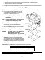
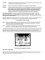
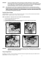
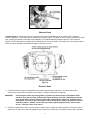
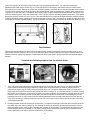
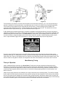
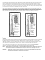
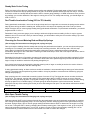
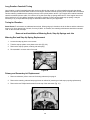
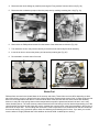
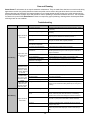
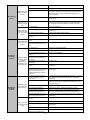
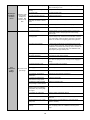
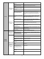
INSTRUCTION MANUAL
LIT701
US Patent # D648746S
www.demoncarbs.com
1
Table of Contents
INTRODUCTION ..................................................................................................................................................................... 3
Recommended Parts and Accessories ............................................................................................................................... 3
Removal of Existing Carburetor .......................................................................................................................................... 3
®
Installation of Street Demon Carburetor ........................................................................................................................... 4
Connecting the Throttle Linkage ......................................................................................................................................... 5
Connecting the Transmission Linkage ............................................................................................................................... 5
GM TH350, 200R4 /700R4 .................................................................................................................................................. 5
Ford Kick-Down Linkage .................................................................................................................................................. 6
Chrysler Applications ....................................................................................................................................................... 6
Vacuum Lines ........................................................................................................................................................................ 7
Electric Choke ....................................................................................................................................................................... 7
Air Cleaner ............................................................................................................................................................................. 8
Priming the Carburetor ......................................................................................................................................................... 8
Mechanical Fuel Pump ...................................................................................................................................................... 8
Electric Fuel Pump ............................................................................................................................................................ 8
Ladies and Gentlemen, Start Your Engines! ...................................................................................................................... 8
Preliminary Tuning and Adjustments ................................................................................................................................. 8
Curb Idle Speed and Mixture Adjustments ......................................................................................................................... 8
Fuel Pressure......................................................................................................................................................................... 9
PERFORMANCE TUNING AND ADJUSTMENT ................................................................................................................. 10
Secondary Air Valve Tuning .............................................................................................................................................. 10
Accelerator Pump Tuning and Adjustment ...................................................................................................................... 10
Main Metering Tuning ......................................................................................................................................................... 11
Theory of Operation ........................................................................................................................................................ 11
Tuning ............................................................................................................................................................................... 12
Steady State Cruise Tuning ........................................................................................................................................ 13
Part Throttle Acceleration Tuning (25% to 75% throttle) ......................................................................................... 13
Choosing the Correct Metering Rod and Step-Up Springs ..................................................................................... 13
Wide Open Throttle Tuning ......................................................................................................................................... 13
Long Duration Camshaft Tuning ................................................................................................................................ 14
Tuning for Elevation .................................................................................................................................................... 14
Removal and Installation of Metering Rods, Step-Up Springs and Jets ....................................................................... 14
Metering Rod and Step-Up Spring Replacement ......................................................................................................... 14
Primary and Secondary Jet Replacement ..................................................................................................................... 14
Winter Fuel ........................................................................................................................................................................... 15
Care and Cleaning ............................................................................................................................................................... 16
Troubleshooting .................................................................................................................................................................. 16
Demon Carburetion™ Limited Warranty .......................................................................................................................... 20
2
INTRODUCTION
Street Demon™ Carburetors™ have many unique features that make them one of the best
performing carburetors in the market! Whether it is street / strip performance, or just getting the most
out of your hot rod, the Street Demon™ will give you optimum performance. This manual will
discuss the special points and unique features of the carburetor, and the correct procedures for
proper installation and tuning. The goal is to help you understand the thoughts behind the Street
Demon™, and to increase your knowledge of carburetion. Please read and understand this manual
completely to assure that you get the most out of your new Street Demon™ carburetor.
If you experience any installation questions, problems, or issues, please contact our technical
service department between the hours of 8AM and 5PM CST M-F @ 1-270-901-3346.
DO NOT RETURN TO THE PLACE OF PURCHASE, unless instructed to do so by technical
service.
Recommended Parts and Accessories
Part Number
1921
1950
1951
1952
1953
1954
160049
124007
786004
1920
Description
Street Demon™ calibration kit
Idle kick-up solenoid and bracket
Street Demon™ TPS kit (for use with electronic transmissions requiring a TPS signal)
GM throttle linkage cable attachment bracket
Throttle cable and transmission kickdown bracket
Ford kickdown spring and perch kit
Universal carburetor installation kit
Chrysler throttle stud
Demon chrome 14” air cleaner assembly
Street Demo™ rebuild kit
Removal of Existing Carburetor
1. Remove the air cleaner, exercising care to carefully detach any vacuum lines from the air cleaner and marking them
so they can be reassembled to the air cleaner in the same manner.
2. Remove the existing carburetor by the following procedure:
A. Carefully disconnect the fuel line.
WARNING:
Carefully protect the open end of the fuel lines, so that no foreign particles can enter. Wrap the
end of the fuel line with a clean lint-free cloth.
B. Disconnect and mark all vacuum lines and wiring (if any) to the carburetor.
C. Disconnect the PCV hose.
D. Disconnect the choke rod or heat tubes (if equipped).
3
E. Disconnect and remove the throttle linkage and automatic kickdown linkage. Save all retaining clips.
F. Unbolt and remove the carburetor from the manifold.
3. If the intake manifold is being changed at this time, install the new manifold according to the manifold manufacturer’s
directions.
Installation of Street Demon® Carburetor
1. Install the carburetor-mounting studs (provided) in the proper location on the intake manifold carburetor flange.
2. Place a new carburetor flange gasket, sealing plate and
second flange gasket provided with the carburetor, in the
proper position on the intake manifold (Fig. 1).
NOTE:
The sealing plate is required for the proper function
of the idle circuit which aids in idle fuel atomization
along with a reduction in heat transfer from the
intake manifold.
NOTE:
If installing the Street Demon™ on a factory cast iron
spread bore style manifold, a spacer may be
required for proper throttle opening.
3. Place the carburetor on top of the flange gasket on the
manifold. Install the hold down nuts and snug down
progressively in a “crisscross” pattern (60-80 in./lbs.).
4. Open and close the throttle a few times to ensure the throttle
operates smoothly with no binding or sticking.
WARNING:
Over tightening may result in a warped or
cracked carburetor throttle body.
WARNING:
Any sticking, binding, or other interference in
the throttle linkage could result in
uncontrolled engine speed. This could result
in engine damage or personal injury.
5. In some cases, the existing fuel line will have to be cut and
connected with a length of rubber fuel hose and a clamp. The
Street Demon™ carburetor comes with three fuel fittings.
5/16” hose barb, 3/8” hose barb (installed) and a 3/8” inverted
flare fuel fitting for a hard line. Select the appropriate fuel fitting
and install into the carburetor making sure to use the new fuel
inlet fitting gasket also supplied in the kit.
Figure 1
Optional Fuel Inlet Fittings
Street Demon™ 9/16"- 24 threaded fuel inlet boss accepts the following optional fittings:
FITTING TYPE
# 6 MALE INLET
#6 MALE INLET
#6 STANDARD
MANUFACTURER
SNIPER
PERFORMANCE
BG FUEL SYSTEMS
EARL’S
PART NUMBER
60406421 (BLUE)
60406423 (BLACK)
142113
991942ERL
If installation requires cutting the metal fuel line, cut the fuel line with a good tube cutter. This will minimize the chance of
producing metal chip particles. If a hacksaw must be used, then metal chips must be removed.
4
WARNING:
During the fuel line installation, DO NOT allow any foreign particles to enter the fuel lines, which
could then cause flooding and may result in a fire.
WARNING:
Keep the fuel line away from the EGR valve (if equipped) on the intake manifold.
WARNING:
In all cases where the fuel line has been cut, it is essential that it be clean to ensure that no metal
particles enter the fuel bowl after the new carburetor installation. Remove the fuel line at the
pump and blow the line clean with compressed air. DO NOT use the procedure where the coil
wire is disconnected, the engine cranked for a few revolutions, and the fuel collected in a
container. This procedure is unsafe because sparking can occur either at the coil or at the
distributor end of the coil wire and ignite any fuel spilled in the engine compartment.
MAINTENANCE WARNING: Fuel system components, including fuel lines and the carburetor, should be
inspected periodically to assure no fuel leakage and to ensure the soundness of the hoses. Today’s clean
emissions engines provide higher temperatures in the engine compartment. These high temperatures promote
faster aging of non-metallic materials.
Hoses that exhibit surface cracks, when bent to 180°, should be replaced. The presence of liquid fuel demands
tightening of fittings, hose replacement, and re-torquing of the fuel system component flange nuts.
Connecting the Throttle Linkage
NOTE:
Before connecting the linkage, operate the throttle lever to assure the correct travel (no sticking or
binding), by opening to wide-open throttle and back to closed throttle several times. Correct any
sticking or binding conditions before proceeding.
NOTE:
If installing on a GM vehicle where the throttle cable needs to utilize the large hole in the top of the
throttle lever, a part # 1952 GM throttle linkage cable attachment bracket will be needed.
With the pedal held firmly against a stop or the floorboard, pull the carburetor to its wide open position. Adjust the linkage
rod or cable to the proper length, and then attach it to the baseplate linkage. Remember, the pedal should make contact
with a positive stop, just as the carburetor gets to wide open throttle. With the linkage rod or cable attached to the
baseplate, make sure the carburetor can return to its curb idle position. Install your return spring(s) to the bottom of the
throttle lever as shown in Figure 2, and check again for smooth operation to wide open throttle, and then closed again .
Figure 2
Connecting the Transmission Linkage
GM TH350, 200R4 /700R4
Attach the transmission kickdown stud (supplied) into the proper hole location on the throttle lever as seen in (Fig. 2).
Attach the TV cable to the stud and adjust per transmission manufacturer’s specifications, using Chilton®, Motor®, or
other repair manual designed for your specific transmission.
5
WARNING:
NOTE:
If you are unfamiliar with overdrive transmission TV cable adjustments, consult a qualified
transmission expert. Failure to properly adjust the TV cable on overdrive transmissions can lead
to poor shifting and / or transmission failure. Demon Carburetion assumes no responsibility for
transmission damage or failure caused by improperly adjusted TV cables.
If this carburetor is to be used in an application utilizing an electronic transmission that requires a
throttle position sensor signal to operate properly, Demon has you covered. Part # 1951 Street Demon
TPS kit is designed to bolt directly to your new Street Demon™ carburetor to provide the needed TPS
signal to an electronic transmission. Consult the installation manual for the 1951 Street Demon TPS kit
for installation and adjustment instructions.
Ford Kick-Down Linkage
All Street Demon™ Carburetors come with a Ford kick-down linkage. If running a Ford automatic and the kickdown
linkage is needed, a spring and perch kit (Part # 1954) is required.
NOTE: Street Demon™ Carburetors will not work with a Ford AOD transmission.
1.
2.
3.
4.
Press the screw retainer into position (Fig. 3).
Remove shipping screw (Fig. 4).
Install adjustment screw and locknut (Fig. 5). Consult the Ford Service Manual for proper setting.
Install the mounting bracket and return spring (Fig. 6).
Figure 3
Figure 4
Figure 5
WARNING:
Figure 6
Install the transmission kickdown adjustment screw retainer, adjustment screw, and locknut, as
correctly indicated. Failure to attend to this detail may result in a sticking wide-open throttle or
dangerous uncontrolled engine speed.
Chrysler Applications
If installing on a Chrysler, it may be necessary to purchase and install a Chrysler throttle stud part # 124007 onto the
Street Demon™ carburetor as in figure 7 below.
6
Figure 7
Vacuum Lines
All Street Demon™ carburetors have four vacuum sources on the baseplate that can be used for PCV, distributor
vacuum, diagnostics, or any other vacuum operated accessories (Fig. 8). The large 3/8" vacuum port, as well as the small
3/16” vacuum port located on the back of the baseplate, is full (below butterflies) manifold vacuum. There is also an
optional 1/4" NPT provision if an additional full manifold vacuum source is needed. The small 3/16" vacuum port located
on the front of the baseplate is timed/ported (above butterflies) vacuum.
Figure 8
Electric Choke
1. Connect the electric choke lead (supplied) to the positive terminal of the choke cap. The other end must be
connected to a good ignition activated 12-volt source. Hookup of this wire is not optional.
WARNING:
Connecting the choke cap to the ignition or ignition coil could result in unacceptable choke
operation, poor fuel economy, and possible engine misfiring, since the voltage delivered to the
spark plugs will be severely reduced by the drain imposed by the choke cap. Suitable ignition
activated 12-volt sources are most electrical relays, as well as the leads to accessories, such as
windshield wipers. DO NOT connect this wire to the original equipment (O.E.) electric choke
source. This may not be a 12V source.
2. Check the voltage source with a volt-ohm meter to assure proper voltage and choke operation. Provision of a good
ground and 12 volt+ source that can supply enough current to the choke cap is essential for proper choke operation!
7
Air Cleaner
1. With some air cleaner configurations, it may be necessary to use an air cleaner spacer to provide adequate clearance
between the carburetor and the air cleaner. Depending on the overall height, obtain the proper length 1/4 x 20 stud
(supplied) and install in the carburetor air horn and trim as necessary. Close the hood slowly to ensure adequate
clearance between the air cleaner stud and the hood. If a longer stud is needed, ¼-20 All Thread can be found at
most hardware or home improvement stores and may be cut to length.
WARNING:
Inadequate clearance between the air cleaner and the throttle lever could result in throttle sticking
and uncontrolled engine speed. Check the clearance between the throttle lever, choke linkage
and air cleaner for proper operation. Check the clearance between the air cleaner and the hood
before closing the hood completely.
Priming the Carburetor
Mechanical Fuel Pump
Crank engine for no more than 30 seconds and then pump the accelerator pedal twice. Have an assistant observe to see
that fuel is being discharged from accelerator pump nozzle when accelerator pedal is pumped. If fuel does not discharge
from accelerator nozzle wait 60 seconds and crank engine again. Note: Engine should not be cranked for more than
30 seconds at time to prevent possible damage to the starting system. Always wait 60 seconds between each
attempt to crank the engine.
Electric Fuel Pump
On vehicles equipped with electric fuel pumps, bump the pump switch on and off to fill the bowls a little at a time. Avoid an
abrupt surge of fuel into an empty carburetor. This can damage the floats and cause flooding. Remember to check for
leaks.
The engine should now be ready to start with a minimal amount of cold cranking.
Ladies and Gentlemen, Start Your Engines!
Get a helper. Unless your car can be started from the engine compartment, starting your engine for the first time should
always be performed with an assistant. A second set of eyes to watch for fuel leaks can be invaluable.
Before engaging the ignition, depress the throttle fully and release once or twice. Now, attempt to start the engine. If the
engine does not fire under reasonable cranking, stop cranking and repeat the process once again. Each engine may
require a different number of pump shots to ease starting. Determine what is best for your engine.
Allow the engine to achieve normal operating temperature before attempting final adjustments to the idle speed or idle
mixture settings. It is however, acceptable to make fuel pressure adjustments during the warm up period.
Preliminary Tuning and Adjustments
The following preliminary adjustments should be made prior to attempting to drive the vehicle.
Curb Idle Speed and Mixture Adjustments
Fine tuning of the idle speed and mixture must be done with the engine at or near operating temperature. A good rule of
thumb is to not attempt adjustments until the engine has achieved 160 degrees water temperature. Adjusting the engine
cold will usually result in a rich mixture at normal operating temperature. It is also helpful to use a tachometer and/or a
vacuum gauge for setting the idle speed and mixture to obtain the highest idle RPM or highest vacuum reading without
adjusting the idle set screw.
8
Ensure the engine is at idle with the choke fully open and at operating temperature. You may now evaluate the
adjustment of the idle mixture screws (Fig. 9). Turning the screws in (clockwise), reduces the amount of idle fuel and
leans the idle air mixture. Backing the screws out (counter-clockwise), increases idle fuel and enriches the idle air mixture.
The idle mixture screws are preset at the factory and SHOULD NOT need any adjustments, however some engines may
require more or less fuel at idle. To adjust the idle mixture, begin by lightly seating both screws and then turning out 2 full
turns as a beginning point. Next, turn each screw in 1/8 to 1/4 turn at a time alternating between each screw. If idle speed
decreases, back the screws out 1/8 to 1/4 turn. Turn them equally until you achieve the highest possible manifold vacuum
or highest idle RPM reading. Adjusting the screws to less than 1 full turn open, can result in an off-idle stumble. Once your
idle mixture screws are adjusted properly, you can now adjust the idle set screw to achieve the desired idle RPM (Fig. 10).
Figure 9
Figure 10
Fuel Pressure
Demon recommends between 5 and 6 PSI fuel pressure at idle. Gasoline carburetors can be run either at idle or wide
open throttle at these pressures. Be sure your fuel delivery system is properly adjusted and able to maintain volume flow
at these pressures. Improperly adjusted or inadequate fuel delivery will result in poor performance and possible engine
damage.
Complete the following steps to tune the electric choke:
Figure 11
Figure 12
Figure 13
1. There are two primary adjustments: the fast idle adjustment screw and the choke timing. The fast idle adjustment
screw controls how far the primary butterflies are open when the choke butterfly is closed or partially closed. It
controls how fast the engine will idle during cold engine warm up. The fast idle adjustment screw is located on the
bracket that is screwed to the throttle shaft, behind the choke housing (Fig. 11). Fast idle can be increased by turning
the fast idle screw clockwise, or decreased by turning it counter-clockwise. It is important to note that when the choke
butterfly is open completely (vertical up and down), the fast idle adjustment screw must not be holding the primary
butterflies open at all. In other words, when the fast idle adjustment screw is at the lowest step on the fast idle cam, it
must not be touching (or making contact) the fast idle cam. See Figure 12 for a view of how the fast idle screw rides
on the steps of the cam.
2. Rotating the black choke cap controls the choke timing. To rotate the choke cap, loosen the three screws that secure
the choke cap to the choke housing (Fig. 13). Rotating the choke cap clockwise will decrease the amount of time it
takes the choke to open, while counter-clockwise will increase the time it takes. This adjustment will depend on your
climate and the vehicle it is installed on. The factory setting can be referenced by making note of where the index
mark is positioned in the cap in reference to the marks on the casting.
9
3. The 14” Demon air cleaner (Part # 786004) is designed to clear the choke plate linkage on all Demon carburetors. If
you use another brand of air cleaner / air cleaner gasket or air cleaner spacer, it is necessary to make sure that the
full range of motion of the choke shaft and butterfly are realized. Failure to do so could result in the choke not
operating properly. This may cause an overly rich condition and/or a high idle condition, which could make the vehicle
hard to control and stop.
CAUTION:
As with any modification, inspection of the part after completion is a must. Before use, check the
linkage for freeness of operation. Your safety depends on it.
PERFORMANCE TUNING AND ADJUSTMENT
Once you have completed the initial installation, and preliminary adjustments, you are now ready to test the vehicle and
evaluate any other possible tuning adjustments. Information on changing the configuration or fuel metering of your Demon
is also included in this section.
Secondary Air Valve Tuning
The secondary air valve door is designed to dampen the transition from primary to secondary operation. Controlled by a
torsion spring, the secondary air valve door is tunable to permit seamless primary to secondary throttle response
regardless of the throttle rate opening.
Figure 14
The factory setting for the secondary air valve door is the most common setting which is one full turn counter-clockwise
after the air valve door is completely closed. If tuning is desired, using a flat blade screwdriver engage the adjusting screw
then loosen the lock nut (If the locknut is loosened before engaging the adjustment screw, the spring tension will be
released - Fig. 14), turn the adjusting screw counter-clockwise to increase spring tension on the door and delay opening.
Turn the screw clockwise to decrease tension and allow the door to open sooner. Tighten the lock nut to hold the adjusted
position. It is not recommended to go beyond one turn more than the factory setting. As an example, you experience a
hesitation or backfire when the secondaries open. This means the secondary air door is opening to quickly, so it is
necessary to adjust the door tighter (counterclockwise) until the hesitation disappears. It is recommended to only adjust
the door ¼ turn at a time an retest for the condition.
CAUTION:
Adjusting the secondary air valve door too loose can cause the door to open a small amount at idle
or low RPM cruising, resulting in an undesirably rich condition.
Accelerator Pump Tuning and Adjustment
When the throttle plates are in the closed (curb idle) position, there should be no play in the accelerator pump connecting
rod. The pump lever should begin compressing the pump stem as soon as the linkage begins to move. Incorrect
adjustment of the pump arm linkage will delay the fuel discharge, and the result is usually a stumble or hesitation as the
butterfly begins to open.
10
Figure 15
Figure 16
The accelerator pump stroke is set at the curb idle position to the dimensions show (Fig. 15). If you are experiencing a
stumble or hesitation on initial acceleration, it is possible that more or less fuel is needed for your particular application.
The connecting rod is positioned in the center hole #2 from the factory. A faster discharge rate is possible if the
connecting rod is relocated to hole #1. A slower discharge rate is possible using hole #3. This requires the rod to be
adjusted to reset the pump stroke (Fig. 16) to the dimension shown in figure 15.
If after adjusting the accelerator pump stroke, a stumble or hesitation is still being experienced, it may be necessary to
change the accelerator pump nozzle. Located under the choke flap, the accelerator pump nozzle has two calibrated holes
which discharge the fuel into the venturii. The Street Demon™ comes with a .028” discharge nozzle from the factory. If
more fuel is needed, a larger discharge nozzle can be used. If less fuel is needed, a smaller discharge nozzle may be
used. Larger camshafts, bigger cubic inch engines or “Air Gap” style manifolds may require a large squirter.
Figure 17
To remove, the accelerator pump nozzle, use a 5/32” Allen wrench to remove the screw from the accelerator pump
discharge nozzle (Fig. 17). Using a pair of needle nose pliers, the discharge nozzle and screw can be removed from the
choke tower area. There are two gaskets used, one under the screw head and the other under the discharge nozzle. Use
extreme caution so the gasket or nozzle is not dropped into the venturii. Re-assemble in the reverse order of removal.
Main Metering Tuning
Theory of Operation
Unlike a traditional Demon carburetor, the Street Demon™ carburetor uses step-up pistons and metering rods for
enrichment. The metering rods protrude through the primary metering jets restricting the amount of fuel flow available.
The metering rods have two steps that are used to restrict fuel flow under various driving conditions. Manifold vacuum is
routed to the step-up piston and that vacuum works to overcome the step-up spring pressure to hold the piston in the
bottom of its bore.
Under a heavy engine load such as acceleration, the engine needs more fuel to operate properly. The extra fuel needed
by the engine is provided by the metering rods, step-up piston springs and step-up pistons. Under a heavy load condition,
there is not enough vacuum available to overcome the step-up spring pressure, therefore the piston rises in its bore and
in-turn raises the metering rod. When the rod is up, the smaller step or rich step of the rod is in the main jet orifice allowing
the extra fuel needed to pass or richen the air/fuel mixture so a desirable air/fuel ratio is maintained.
11
On the other hand, when the engine is under a light load such as idle or steady state cruising, the engine does not need
extra fuel. Under light load, there is adequate vacuum to overcome the step-up spring tension, therefore the step-up
piston stays in the bottom of its bore which also positions the metering rod at the lowest position. When the metering rod
is down or at its lowest position, the large step or lean step of the metering rod is in the main jet orifice restricting fuel flow
or leaning out the air/fuel mixture so a desirable air/fuel ratio is maintained.
Figure 18 is a cutaway view of the enrichment circuit in a light load condition such as idle or steady state cruising. The
step-up piston is in the bottom of the bore and the lean step of the metering rod is in the jet, therefore restricting fuel flow
so the desired air/fuel ratio is maintained. Figure 19 represents the enrichment circuit in a heavy load condition such as
wide open throttle. The step-up piston is in the top of the bore and the rich step of the metering rod is in the jet.
Figure 18
Figure 19
Tuning
Tuning is best completed by using a wide band oxygen sensor to monitor air fuel ratios, however tuning can be performed
by reading spark plugs and taking vacuum readings. Manifold vacuum will increase the closer you get to an ideal
calibration; it will fall off once you get past this point. The ideal color for the spark plug porcelain is light brown or tan. A
color lighter than this indicates that the carburetor is lean; a darker color indicates that the carburetor is rich.
There are a few different areas that need to be looked at separately when it comes to tuning a Street Demon™
carburetor. These areas are; steady state cruise, part throttle acceleration and wide open throttle.
NOTE:
Before making any tuning changes, it is recommended that all test drives for steady state cruising and
part throttle acceleration are completed before making any changes to the metering rods or jets.
WARNING:
Always take a helper with you to watch and record vacuum or AFR readings. Never try to drive
and write at the same time as it could result in an accident.
12
Steady State Cruise Tuning
Earlier, the theory of how the main metering system works was explained. During steady state cruising, there is enough
vacuum to overcome the step-up spring tension so the rod is in the down position and the lean step is in the jet. It is best
to drive the vehicle at a steady state and record the AFR or vacuum gauge reading in 10 MPH increments. Once you have
the readings, you can then determine if the engine is running rich or lean. For steady state cruising, you should target an
AFR of 13.5 to 1.
Part Throttle Acceleration Tuning (25% to 75% throttle)
During part throttle acceleration, vacuum in the engine drops and is no longer able to overcome the spring tension and the
step-up piston will rise as will the metering rod. At this point, the rich step of the metering rod will be in the jet. Have a
helper record the AFR or vacuum gauge reading during part throttle acceleration. For part throttle acceleration, you should
target and AFR of 12.5 to 1.
Remember if using a vacuum gauge, you are tuning to achieve the highest vacuum reading. At first, it may be a guess
whether it is too rich or too lean. Once you make a change, you will be able to tell by the new vacuum reading if you went
the wrong way or not.
Choosing the Correct Metering Rod and Step-Up Springs
(See next page for instructions on changing rods, springs and jets)
Once you have the readings from the steady state cruising and part throttle acceleration, you can now choose the proper
metering rod. For example; your carburetor currently has a metering rod with a .060” lean step and a .052 rich step.
During testing it is determined that during steady state cruising the engine is a little lean and during part throttle
acceleration, the engine is also a little lean. A metering rod with a lean step of .058” and a rich step of .050 can be used to
richen both of these areas up.
Remember from the theory of operation, the steps in the metering rod go into the jet orifice essentially restricting fuel flow.
So to richen the mixture, a smaller rod step is needed to allow more fuel to pass through the jet and to lean the mixture a
larger rod step is needed to restrict the fuel passing through the jet.
If the desired result cannot be achieved by changing metering rods, a larger or smaller jet can then be used to richen or
lean the mixture in combination with the metering rods.
If during part throttle testing, an issue such as a stumble or hesitation is encountered that goes away upon further throttle
opening. The engine may be experiencing a lean condition. It may be possible to correct the lean condition by going to a
stronger step-up spring.
Step up springs are color coated and are rated by inches of vacuum of “Hg. The bigger the vacuum number, the heavier
the spring is. For example; a spring with a rating of 8”Hg means that it takes 8 inches of vacuum or more to keep the
spring from raising the step-up piston. A spring with a rating of 3”Hg only takes 3 inches of vacuum to keep it from raising
the step-up piston so it is a weaker spring. A heavier spring will allow the piston to rise in its bore sooner, therefore
placing the rich step of the metering rod into the jet orifice eliminating the lean spot. The chart below outlines the available
step-up springs.
Spring Color
Rating in “Hg
Blue
3”Hg
Yellow
4”Hg
Orange
5”Hg
Green
6”Hg
Silver
8”Hg
Wide Open Throttle Tuning
(See next page for instructions on changing rods, springs and jets)
Wide open throttle (WOT) tuning is best performed after the steady state cruise and part throttle acceleration is complete.
WOT tuning is best performed using a dyno or at the drag strip. DO NOT attempt to perform wide open throttle tuning on
the street. Using a helper, AFR or vacuum gauge readings should be taken at WOT to determine if the engine is running
rich or lean. Tuning the WOT is done by changing the secondary metering jets. If the engine is to lean, go up a couple of
steps in the secondary metering jets, if it is too rich; go down a couple of sizes in the secondary metering jets. It is not
recommended to go more than two sizes at a time so that it is easier to monitor the changes.
13
Long Duration Camshaft Tuning
Long duration or radical camshafts generally need more idle air than a stock or mild camshaft and require the throttle
plates to be opened more than that of a stock or mild engine. Excessive throttle opening at idle coupled with low manifold
vacuum makes it possible that the metering rods are in the up/rich position at idle. If your engine has a radical camshaft,
check the manifold vacuum at idle, if it is above 10” Hg the stock step-up springs will work fine. If the engine vacuum at
idle is less than 8-10” Hg it will be necessary to change to a lighter or lower vacuum rated step-up spring. It may be
necessary to try a couple different springs to determine which is best for your application.
Tuning for Elevation
Street Demon™ carburetors are calibrated at sea level. When going up in elevation, the air is thinner and the carburetor
may run rich. As a general rule of thumb, for every 2,000 ft. in elevation, the metering rod diameter should be increased
.002” on the lean and rich steps.
Removal and Installation of Metering Rods, Step-Up Springs and Jets
Metering Rod and Step-Up Spring Replacement
1. Loosen the step-up piston cover screws.
2. Twist the step-up piston cover plates to the side (Fig. 20).
3. Remove the step-up piston, metering rod and spring.
4. Re-assemble in reverse order of removal.
Figure 20
Primary and Secondary Jet Replacement
1. Remove carburetor (refer to removal of existing carburetor) on page 4.
2. Remove the metering rods and step-up pistons as outlined in (metering rod and step-up spring replacement)
3. Remove the two Phillips head screws from the top of the carburetor (Fig. 21).
Figure 21
14
4. Disconnect the choke linkage by carefully removing the E-ring retainer from the choke rod (Fig. 22).
5. Disconnect the accelerator pump rod from the pump arm by carefully removing the c-clip (Fig. 23).
Figure 22
Figure 23
6. Remove the six Phillips head screws from the bottom of the carburetor as circled in (Fig. 24).
7. The carburetor air horn may now be carefully removed from the main body/fuel bowl assembly.
8. Invert the air horn to access the primary and secondary metering jets (Fig. 25)
9. Re-assemble in reverse order of removal.
Figure 24
Figure 25
Winter Fuel
Different fuels are used in the United States in the summer and winter. These fuels can even differ depending on what
part of the country you are in. Winter fuels have a higher Reid Vapor Pressure than summer fuels. In other words, the fuel
boils at a lower temperature than that of a summer blend. Most of the time this does not cause issues with drivability,
however in early fall or late spring when summer temperatures may still be present and winter fuels are in use it may
cause drivability issues. The most common problem observed is the fuel boiling in the fuel bowl and percolating out of the
vent tubes after the engine is shut down after a drive. Another less common issue is the fuel evaporating in the fuel line or
also known as vapor lock. The best thing that can be done if this is experienced is to isolate the fuel lines and carburetor
from excess heat by using a phenolic spacer under the carburetor and insulating the fuel lines. If you store your vehicle
over the winter it is highly advised that a fuel stabilizer such as STA-BIL is added prior to storing.
15
Care and Cleaning
Street Demon™ carburetors do not require extensive maintenance. They are made from aluminum so over time the shiny
appearance can dull. Any quality aluminum cleaner and polish can be used to bring the shine back to as new condition.
Always clean the part first with a mild soap and water or non-vinegar based window cleaner, then polish as instructed by
the polish manufacturer. Always use a new microfiber cloth for polishing or unwanted scratches can occur. The composite
fuel bowl on the part # 1902 Street Demon™ does not require any type of polishing; cleaning with a mild soap and water
will bring it back to new condition.
Troubleshooting
PROBLEM
CONDITION
CORRECTION
1) Inspect choke adjustment and for something binding. Adjust,
if necessary.
2) Choke linkage binding.
2) Lube with WD-40 and check for something bent. Adjust if
necessary.
3) No gas in carb.
3) Check fuel delivery. Look for plugged filter or clogged lines,
bad pump, stuck needle & seat, and fuel pressure.
4) Accelerator pump defective or
worn out.
4) Replace the pump. Problem is usually caused by bad gas,
dirt in gas, or vacuum leak or ignition problems.
5) No spark or engine problems
such as bad compression.
5) Diagnose & correct the problem.
1) Choke not closing properly.
1) See notes above. Adjust choke if necessary.
2) Big vacuum leak on engine
somewhere.
2) Use vacuum gauge to check. Fix the leak. You may have put
the base gasket on wrong or it is the wrong one for this carb &
engine combination.
3) Fast idle RPM set too slow.
3) Adjust to recommended RPM.
4) Low fuel delivery.
4) Correct delivery to carb. Usually it is a plugged up filter.
5) Electrical or compression
problems on the engine.
5) Do complete tune up & diagnosis. Fix the problem.
6) Float level set very low.
6) Check & adjust float level to factory specs.
Engine normally
starts OK but then
dies backing out
driveway or at first
stop sign. After that
it runs OK.
1) Choke setting too lean
1) Richen choke by adjusting cap counter-clockwise
Engine starts OK,
increases RPM
then gets too slow
with lots of black
smoke.
1) Choke set too rich
1) Lean choke by adjusting cap clockwise
2) Slow flooding.
2) Fix cause of flooding.
3) Float level very high.
3) (Rare) Set to factory specs.
1) Big vacuum leak somewhere.
1) Correct the vacuum leak. Make sure you haven't forgotten to
hook up a hose somewhere. Base gasket may be wrong one or
on wrong.
1) Carburetor flooding.
1) Fix cause of flooding.
2) Choke is closed when engine
is hot.
2) Find & fix cause for choke staying closed. Check power and
ground, make sure power wire has a full 12v or something
jammed or bent, check choke linkage to air cleaner clearance
3) No fuel
3) Check fuel delivery volume and pressure. Look for clogged
lines, filter, or pump. Check for kinked or swollen fuel lines.
4) No air.
4) Check for clogged air filter, especially after driving through
muddy or dusty area.
5) Too much air.
5) Look for big vacuum leak, such as broken hose, blown
gasket, bad power brake diaphragm, bad PCV valve (Rough
Idle).
Engine cranks but
will not start
Cold Starting
POSSIBLE CAUSE
1) Choke not closing.
Engine starts, then
dies within a few
seconds.
Engine starts, then
races for a few
seconds and then
dies every time.
Warm Starting
Engine cranks but
will not start.
16
Engine starts, then
dies within a few
seconds.
Warm Starting
(Cont.)
Engine starts, then
races for a few
seconds and then
dies.
Engine starts OK,
but then gets real
rough. Lots of black
smoke.
Engine stalls when
transmission is put
into gear.
Cold Engine
Drivability
Condition
Warm Engine
Drivability
Condition
Hesitation, stalling,
stumbling, dead
spot during
acceleration:
Backfiring or spit
back through carb.
Hesitation under
light throttle: dead
spot & stumble.
Doggy, runs rough,
lots of black smoke
at idle.
1) Choke is staying closed
1) Diagnose and fix choke problem.
2) Carburetor flooding.
2) Fix cause of flooding.
3) Venting system failure.
3) Check out entire fuel system venting system, including the
vent valve on the carb, the charcoal canister, all hoses & check
valves in the system, and any solenoids that trigger the vent
system to operate.
4) Step-Up Piston up in bore
4) Remove step-up piston and fix sticking issue or use a lighter
step-up spring
1) Big vacuum leak somewhere.
1) Find the vacuum leak & fix it. Also look for wrong base gasket
or one that is installed wrong. If engine has been spitting back, it
may have blown out the base gasket or a gasket in the carb.
1) Slow flooding.
1) Fix cause of flooding.
2) Step-Up Piston up in bore
2) Remove step-up piston and fix sticking issue or use a lighter
step-up spring
3) Venting system problem.
3) Check entire venting system & repair.
4) Fuel dripping from secondary
nozzles
4) Tighten secondary air door ¼ turn counterclockwise
1) Fast idle RPM incorrect (too
slow)
1) Speed up the fast idle to factory specs.
2) Engine running too lean
because of vacuum leak or dirty
jet.
2) Check for vacuum leak. Flow test carb to check jetting.
1) Vacuum leak.
1) Check for vacuum leak & repair.
2) Ignition timing retarded too far.
2) Reset timing.
3) Accelerator pump nozzle has
dirt in it.
3) Clean out the nozzle tip.
4) Accelerator pump cup swollen
up from contact with bad gas or
chemicals.
5) Secondary air door opening
too quickly
4) Replace the pump cup.
6) Vacuum hoses hooked up
wrong.
6) Connect up right. Be especially careful of the EGR & Dist.
connections
7) Distributor timing not
advancing properly (worn breaker
plate, worn shaft, pin hole in
distributor diaphragm, cracked
hose, etc.)
7) Check distributor and all related systems carefully. Replace
defective parts.
1) Vacuum leak somewhere, or
hose off or hooked to wrong
vacuum port.
1) Inspect hoses. Route and lead the hoses correctly. Look for
leaks caused by the wrong base gasket or if it was installed
upside down.
2) Accelerator pump problems.
2) Inspect and adjust pump stroke, pump plunger, discharge
nozzles and check valves. Inspect the accelerator pump, look
for swollen pump cup.
3) Float level set very low.
3) Set float to factory specs.
4) Ignition timing retarded.
4) Set to factory specs. Make sure advancing correctly.
5) Idle speed set too fast &
mixture is too lean (common)
5) Richen up the idle mixture, reset the idle speed to factory
specs., then reset the mixture using the lean drop method.
6) EGR valve stuck on or coming
on too early (hose on wrong?)
6) Inspect hose routing to EGR valve & inspect valve. Replace
as necessary.
1) Choke staying closed or partly
closed.
1) Fix choke or heat source.
2) Slow flooding.
2) Fix cause of flooding.
3) Step-Up Piston up in bore
3) Remove step-up piston and fix sticking issue or use a lighter
step-up spring
4) No power to choke.
4) Repair as necessary.
5) Secondary Air Door or Goggle
Valve stuck or partially open
5) Find cause and repair
17
5) Adjust air door
Warm Engine
Drivability
Condition
(Cont.)
Poor
Performance
or Gas
Mileage
Hesitation under
heavy throttle:
Dead spot &
stumble. May
backfire or spit
back.
No power or bad
gas mileage.
1) Defective accelerator pump.
1) Look for dirt in pump nozzles, swollen cup from bad gas, or
check ball missing or stuck.
2) Metering rods sticking or
binding.
2) Repair as necessary.
3) Vacuum leak.
3) Locate leak and repair.
4) Float level setting very low.
4) Reset to factory specs.
5) Plugged up fuel filter, defective
fuel pump, or swollen or kinked
lines.
5) Inspect and repair as necessary.
6) Secondary air valve set wrong.
6) Check & adjust the secondary air valve spring.
7) Ignition timing retarded.
7) Set to factory specs. Make sure advancing correctly.
1) Plugged exhaust.
1) Check exhaust. Look for plugged catalytic converter, bad
muffler baffle, kinked or crimped pipe, dirt or other foreign
matter in pipe.
2) Clogged gas tank vent, or fuel
venting system.
2) Remove gas cap & see if performance improves. If so clean
or replace the gas cap. Check the charcoal canister, hoses to it
& any check valves. Check the electric vent valve on the carb if
there is one, & make sure it is getting power at the right time.
3) Ignition timing retarded
3) Check timing at idle and also for full advance when revved
up. Look for bad or loose hose, hose hooked up to wrong pipe
on distributor, bad thermal switch, leaking vacuum advance can
on the distributor, a worn breaker plate, worn distributor shaft,
sticky weights, point gap closed up, etc.
4) Clogged air filter
4) Replace air filter.
5) Choke not opening
5) Fix choke or power source problem.
6) Secondary not opening.
6) Check for sticky or bent shaft or linkage. Check secondary air
door, check the spring tension & metering rods for dragging or
sticking.
7) Wrong main jets or rods.
7) Check and replace, as necessary.
8) Dragging brakes.
8) Fix brake problem.
9) Low tire pressure.
9) Increase tire pressure to factory specs.
10) Automatic Transmission
malfunction.
10) Diagnose & fix automatic transmission.
11) Wrong or malfunctioning
thermostat in cooling system.
11) Replace thermostat.
12) Blocked or leaking exhaust
heat passage in intake manifold.
12) Remove manifold & fix it.
13) Defective accessory (power
steering pump, air conditioning
compressor, etc.) causing drag
on engine.
13) Diagnose & repair or replace the accessory unit.
14) Wheels out of alignment.
14) Have wheels professionally aligned.
15) Poor driving habits.
15) Reduce speed, quick acceleration, screeching around
corners etc.
16) Float level too high, or float
partly sunk.
16) Set to factory recommendations, & check float weight,
replace if necessary.
17) Ignition problems or needs a
tune up.
17) Do complete tune up & physically inspect the cap, rotor,
wires, coil, plugs, points, etc. in addition to checking on the
scope.
18
Gas pours out
when engine
turned off.
Flooding
Gas pours out
when the engine is
running.
Engine stalls when
transmission is put
into gear.
Hesitation
During
Acceleration
Hesitation, stalling,
stumbling, flat spot,
or dead spot during
acceleration:
Backfiring or spit
back up through
carb.
1) Charcoal canister is saturated
with gas.
1) Replace the charcoal canister.
2) Winter fuel
2) Isolate heat to carburetor or get summer fuel is possible
3) Kinked hoses in venting
system.
3) Replace the kinked hoses with correct kind.
4) Stuck or blocked check valves
in the vent hoses or elsewhere in
the system.
4) Replace the check valves.
5) Gas tank vent is blocked.
5) Fix or replace the gas cap if vent is in the cap.
6) Gas line located too close to a
heat source (such as a radiator
hose or exhaust manifold).
6) This causes the fuel to expand & be forced past the needle &
seat. Also, fuel can boil in the carb if there are improper or
missing gaskets or spacers between the carb & manifold. A heat
riser stuck in the closed position will also cause boiling and
flooding.
1) Dirt stuck on tip of the needle
& seat.
1) Clean the tip off carefully or replace the needle and seat &
clean the entire fuel system out. Check for defect canister,
causing debris or fuel contamination.
2) Idle speed is set too fast.
2) Reduce the idle speed to factory specs. If it will not idle
slowly, the mixture is set too lean, or there is a vacuum leak
somewhere (usually not in the carb).
3) Fuel pump pressure too high.
3) Check pressure. Use a regulator to control the pressure or
put on a new pump (don't use high pressure type).
4) Gas is very gummy, old, or has
too much alcohol or other
chemicals in it.
4) Clean bad gas out of carb. Clean out of fuel system. Use only
good quality gas.
5) Choke not working.
5) Check cause of choke failure, choke pull-off failure, or loss of
power to the choke.
6) Needle not seated properly
during initial fill.
6) Try tapping the fuel inlet or needle & seat area with the
handle of a screwdriver.
1) Fast idle RPM incorrect (too
slow)
1) Speed up the fast idle to factory specs.
2) Engine running too lean
because of vacuum leak or
misadjusted idle fuel mixture
2) Check for vacuum leak. Adjust idle fuel mixture. Check for
vacuum leak.
1) Vacuum leak.
1) Check for vacuum leak & fix it.
2) Ignition timing retarded too far.
2) Reset timing.
3) Accelerator pump nozzle has
dirt in it.
3) Clean out the nozzle tip.
4) Accelerator pump cup swollen
up from contact with bad gas or
chemicals.
4) Replace the pump cup.
5) Vacuum hoses hooked up
wrong.
5) Connect up right. Be especially careful of the EGR & Dist.
connections
6) Distributor timing not
advancing properly. (worn
breaker plate, worn shaft, pin
hole in diaphragm, crack in hose,
etc.)
6) Check distributor and all related systems carefully. Replace
defective parts.
7) Secondary air door adjusted
too loose
7) Tighten air door ¼ turn counterclockwise
8) Incorrect accelerator pump
nozzle
8) Install a larger accelerator pump nozzle
19
Hesitation
During
Acceleration
(Cont.)
Hesitation, dead
spot or stalling that
only seems to
occur after the first
mile of warm-up.
Compression or
Misfiring
1) Defective electric assist on
choke
2) Defective accelerator pump
(low output).
1) Replace it.
3) Float level setting very low.
3) Adjust to factory specs.
1) Run a compression check.
1) This will isolate bad rings, or valves, worn cylinder walls,
defective cylinder head or gaskets and excessive carbon
deposits.
2) Check dwell variations.
2) Check at variable speeds for excessive distributor shaft wear,
faulty
2) Replace it.
For further questions, please contact our technical department at 1-270-901-3346.
Demon Carburetion™ Limited Warranty
All Demon Carburetion™ Limited Warranties are extended to the original consumer only. This Limited Warranty is not
assignable or otherwise transferable. There are no warranties that extend beyond those stated herein. Demon
Carburetion™ offers no other warranties expressed or implied beyond this Limited Warranty.
In the event of an alleged defect in material or workmanship, the responsibility of Demon Carburetion™ is strictly limited to
the repair or replacement of the defective product. Demon Carburetion™ has no other obligation expressed or implied.
Final warranty determination will be in the sole discretion of Demon Carburetion™. Demon Carburetion™ shall not be
responsible for; (a) actual or alleged labor, transportation, or other incidental charges; or (b) actual or alleged
consequential or other damages incurred by use of any product of Demon Carburetion™.
To initiate the warranty process, the consumer must return the alleged defective product to the place of purchase with a
dated receipt and completed applicable warranty claim tag. Warranty claims will be rejected if the date of purchase cannot
be established by the consumer. Do not send products directly to Demon Carburetion™. Demon Carburetion™ assumes
no responsibility for products sent directly to Demon Carburetion™.
This Limited Warranty sets forth specific legal rights. The consumer may have other rights as a result of variations in state
laws or provincial laws. This Limited Warranty supersedes all prior warranty statements.
DEMON CARBURETION™ – NEW PRODUCT
Demon Carburetion™ warrants its new products to be free from defects in material and workmanship for a period of 90
days from date of purchase.
Demon Carburetion™ Limited Warranty specifically does not apply to products, which have been (a) modified or altered in
any way; (b) subjected to adverse conditions, such as misuse, neglect, accident, improper installation or adjustment, dirt
or other contaminants, water, corrosion, or faulty repair; or (c) used in other than those applications recommended by
Demon Carburetion™. Demon Carburetion™ also does not warrant, and disclaims all liability for products used in racing
activities and/or applications other than those specifically recommended in the current brand catalog.
NOTE: IF YOU HAVE ANY QUESTIONS ABOUT THE SETUP OR TUNING OF THIS CARBURETOR, PLEASE
CONTACT THE DEMON CARBURETOR™ TECHNICAL DEPARTMENT DIRECTLY AT 270-901-3346.
Return Address & Contact information:
Demon Carburetion™
1801 Russellville Road, Bowling Green, KY 42101
Ph: 270-901-3346
www.demoncarbs.com
© 2012 Demon Carburetion™ All rights reserved.
LIT701
Revision Date: 5-17-12
20