1
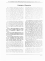
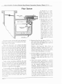
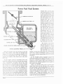
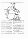
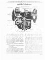
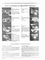
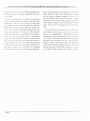
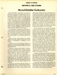
for
MARVEL-SCHEBLER
TRACTOR and INDUSTRIAL
CARBURETERS
MODELS DLTX & TSX
MARVEL-SCHEBLER PRODUCTS DIV.
BORG-WARNER CORPORATION
DECATUR, ILL., U S.A.
FORM
NO ME
184
Marvel-Schebler Products Division, Borg -Warner Corporation, Decatur, Illinois, U. S. A.
Principle of Operation
Marvel-Schebler C a r b u r e t e r s a r e u s e d on
thousands of tractor a n d industrial engines and
have been designed to provide many years of
trouble-free service, however, as in t h e case of
all mechanical devices, they do in time require
;,roper service a n d repairs. An understanding
of their construction a n d how they operate a s
well as a n understanding of their function with
respect to t h e engine will not only avoid many
false leads on t h e p a r t of t h e service m a n in diagnosing so-called carbureter complaints but will
create customer satisfaction a n d a profitable
business f o r t h e progressive service shop.
To understand a carbureter i t is necessary to
realize t h a t there is only one thing t h a t a carbureter is designed t o do a n d t h a t is t o mix fuel and
a i r in t h e proper proportion so t h a t t h e mixture
will burn efficiently in an engine. It is t h e function of t h e engine to convert this mixture into
power.
There a r e three major factors in an engine
which control t h e change of fuel a n d a i r into
power: 1-Compression.
2-Ignition.
3-Carburetion.
Carburetion has been listed last because it is
absolutely necessary f o r t h e engine to have good
compression a n d good ignition before it can have
good carburetion.
When the average person thinks of "carburetion" they immediately think of t h e carbureter
as a unit. Carburetion is t h e combined function
of the carbureter, manifold, valves, piston and
rings, combustion chamber, a n d cam shaft.
It can be readily seen t h a t "carburetion" is a
f a r deeper subject than consideration of t h e carbureter alone, and expecting t h e carhureter to
cure faulty ignition, compression, valves, etc. will
only result in wasted time a n d effort on t h e p a r t
of t h e service m a n a n d added expense to t h e
customer.
It must be remembered t h a t t h e function of
the carbureter does not extend beyond deliver~ n p
t h e proper mixture of fuel and a i r to t h e
manifold a n d t h e other factors which effect
power a n d economy cannot be changed o r corrected by t h e carbureter. Inability t o understand
all t h e factors t h a t effect engine operation is t h e
reason many service mechanics change from factory standards a n d attempt to improve on t h e
engine set-up by their own methods or "standards". All t h a t any service mechanic should ever
try to do is to make t h e particular engine h e is
working on as good as t h e manufacturer intended i t to be, b u t he can m a k e i t a lot worse.
F a r too many engines a r e running below their
standard of performance in service today.
F o r the carbureter to accomplish its function
it must be able to vary t h e mixture strength dependent upon t h e engine demands. It must
supply a mixture strength t h a t urill allow t h e engine to give maximum horsepower, whenever t h e
throttle is fully opened, while a t p a r t throttle
conditions it must lean out t h e mixture so that
maximum economy can be obtained. In addition
it must have flexibility throughout the entire
range of operating speeds, from idle and p a r t
throttle to full power wide open throttle position. The carbureter must also have a n accelerating "well" with enough fuel capacity to start
handling sudden maximum loads. In other words
the carbureter not only varies t h e volume of fuel
and a i r t h a t enters t h e engine but also varies t h e
amount of fuel t h a t goes in with a given amount
of air, h order to produce t h e proper mixture
proportion for any condition under which t h e
engine is operating a t any time.
In order to understand t h e function a n d operation of t h e Marvel-Schebler Tractor and Industrial Carbureters i t is well to consider t h e systems
t h a t make up each carbureter. These systems
a r e : The F l o a t System, T h e Idle System, The
Power Fuel Feed System, The Back Suction
Economizer System, a n d The Choke System.
A thorough knowledge of each system will
help t h e service mechanic to quickly locate a n d
correct legitimate carbureter complaints as well
a s t o inspect, repair, a n d put back to standard
a n y carbureter t h a t requires a n overhaul.
Marvel-Schebler Products Division, Borg-Warner Corporation, Decatur, Illinois, U. S. A.
Float System
FLOAT VALVE
FLOAT VALVE-3
FUEL BOWL-!
The float system controls t h e level a n d supply
of gasoline in the fuel bowl throughout t h e operating range of t h e engine.
When t h e fuel bowl (1) is empty t h e float
and lever (2) and float valve ( 3 ) drop a n d fuel
under pressure from t h e fuel pump (or gravity
feed) is forced through t h e float valve seat (4)
around t h e float valve ( 3 ) a n d into t h e fuel
bowl (1). As t h e fuel in t h e bowl approaches
the correct operating level i t raises t h e float a n d
lever (2) with enough force t o raise t h e float
valve and cut off t h e flow of fuel into t h e bowl.
As fuel feeds through t h e carbureter jets into
t h e engine t h e fuel level (5) drops, allowing
additional fuel to enter t h e fuel bowl.
Under actual operating conditions t h e fuel
level (5) and float and lever (2) automatically
position themselves so t h a t t h e inward flow of
gasoline to t h e carbureter is equal to t h e outward flow of gasoline t o t h e engine.
As can readilv be seen t h e float system under
the most favorable of operating conditions is
subjected to a certain amount of wear. Under
severe conditions or conditions t h a t result in excessive vibrations being transmitted to the carbureter, float valve a n d float valve seat wear is
accelerated.
It should be an established policy t h a t whenever t h e carbureter is disassembled f o r whatever
c a u s e t h e service m a n
make following checks:
1. Examine float valve for
any signs of wear. If i t
is not absolutely true or
is grooved a n d hasn't a
perfect taper, a new
float valve and also a
n e w f l o a t valve s e a t
must be used. These
float valves a n d seats
a r e supplied in matched sets and a r e tested
a t t h e factory for leaks.
Always use a new float
valve s e a t g a s k e t t o
make sure of a perfect
seal.
2. Examine float for any signs of failure. To
test metal float submerge float in pan of
hot water and if a i r bubbles a r e observed
replace with new float.
Examine cork float f o r bare places or
cracks in coating. If either a r e found, or if
float shows evidence of having been soggy,
replace with new one. (Do not attempt to
recover float with shellac or varnish.)
3. Set float height to t h e proper specification
for the particular model carbureter being
serviced. Make certain t h a t t h e entire
assembly works f r e e a n d t h a t there is no
binding.
4. Wash fuel strainer assembly in gasoline
and clean screen with air under pressure.
If the screen, or t h e threads on t h e strainer
a r e not in good condition, install a new
assembly. W h e n re-installing fuel strainer
assembly always use a new strainer gasket
if a gasket is used t o obtain a seal.
I t has been proven, with few exceptions,
t h a t with a float system in good order,
carbureter flooding only occurs when dirt
or foreign matter becomes lodged between
the float valve ( 3 ) a n d float valve seat ( 4 ) .
Marvel-khebler Products Division, Borg-Warner Corporation, Decatur, Illinois, U. S.A.
The Idle System
PRIMARY IDLE
ORIFICE-7
IDLE
NEEDLE-13
SECONDARY
IDLE ORIFICE-8
IDLE ADJUSTING
NEEDLE SEAT-I2
t h e throttle valve ( 6 ) since
this valve must be slightly
open to permit t h e engine
to idle. The resultant mixt u r e is correct f o r operating engine a t idle speed,
provided t h e idle adjusting needle (13) is prop-
erly adjusted.
As t h e throttle valve ( 6 )
is slowly opened from t h e
slow idle position i t gradually subjects t h e seconda r y idle orifice (8) t o int a k e manifold vacuum,
a n d t h e secondary idle
orifice ( 8 ) no longer bleeds
air t o t h e idle fuel passage
(10) but feeds a n additional quantity of fuel into
t h e engine. This is proper since t h e throttle valve
is now open wider a n d will admit a greater
amount of a i r to blend with this additional fuel
to maintain the correct proportions of fuel a n d
air for the engine.
FUEL BOWL
CHAMBER-9
The idle system controls t h e Aow of fuel a t
idle speed and a t slow speeds until t h e throttle
is opened wide enough t o allow t h e power fuel
feed system t o function.
When t h e throttle valve (6) is in t h e idle position the edge of t h e valve is between t h e primary
idle orifice (7) and the
idle orifice
( 8 ) . With t h e valve in this position t h e air pressure (manifold vacuum) a t t h e primary idle
orifice (7) is lower than t h e a i r pressure in t h e
fuel bowl chamber (9) a n d fuel is forced from
the fuel bowl (1) into t h e idle fuel passage (10).
As t h e fuel travels through t h e idle fuel passage
(10) i t passes through t h e metering orifice of
the idle jet (11) to t h e point where it is combined
with a i r entering through the idle adjusting
needle seat ( 1 2 ) . The mixing of air with gasoline
helps to atomize t h e fuel a n d this Process is
repeated a t t h e secondary idle orifice ( 8 ) a s t h e
fuel travels through t h e idle fuel passage (10).
As this rich mixture of fuel and air ernergesfrom
the primary idle orifice (7) it is reduced to caruect proportions by t h e a i r which passes around
As t h e throttle valve ( 6 ) is opened still wider,
t h e idle fuel delivery begins to f a d e out, howcver, t h e throttle valve a t this point is f a r enough
open for t h e power fuel f e e d system t o begin
functioning.
The idle system a s described above is t h e most
positive a n d satisfactory of idle systems, as it is
working under very high suction a n d t h e mixture
flows through t h e small passages a n d orifices a t
very high velocities. It is necessary to bear in
mind, however, that there are times
these
small holes may
plugged \vith particles
of dirt or foreign matterand will
clean.
ing. A t such times t h e passages, jets, and small
drilled holes should only be cleaned with a
cleaning fluid such as gasoline and air under
pressure. Never use drills or wires as a change
in size of these small openings will change t h e
entire calibration of t h e carbureter.
Page 3
Marvel-Schebler Products Division, Borg-Warner Corporation, Decatur, Illinois, U.S. A.
Power Fuel Feed System
THROTTLE VALVE-6
NOZZLE AIR VENT-21
FUEL BOWL
CHAMBER-9
POWER JET-20
POWER ADJUSTING NEEDLE-18
With the throttle valve (6) in slow or just off
slow idle position, fuel rises up through the
nozzle (14) and out the nozzle air bleeds (15)
to fill the accelerating well (16) to approximately the height of the fuel level in the fuel
bowl ( 1 ) .
As the engine speed is increased from the
slow idle position the air flow through the venturi
(17) is gradually increased, and, as the idle
system begins to diminish,the velocity through
the venturi (17) is high enough to create a pressure a t the tip of the nozzle (14) slightly less
than the pressure in the fuel howl chamber (9)
and the accelerating well (16). Fuel, therefore,
feeds from the fuel bowl (1) through the opening between the power (load) adjusting needle
(18) and the power adjusting needle seat (19),
through the power jet (20) and out the nozzle
(14) to be discharged into the air stream a t the
Parre 4
venturi (17). At the same
time, the fuel that is stored
in t h e accelerating well
(16) is also forced through
the nozzle air bleeds (15)
into the nozzle (14). But,
because the size of the
power jet (20) and the
position of the power adjusting needle (18) restrict
the amount of fuel which
can enter the nozzle (14),
the fuel in the accelerating well (16) will soon be
exhausted and a i r will
then e n t e r through t h e
nozzle air bleeds (15) to
mix with the fuel passing
through the nozzle (14).
The amount of air that can
enter into the nozzle (14)
is limitcd by the size of
the nozzle air vent (21).
The result of air bleeding into the nozzle (14) is,
to help atomize or break
ua the fuel into finer particles, to regulate the quantity and the rate of discharge of the fuel fed from the accelerating
well ( I F ) , during acceleration, and to inovide
the correct mixture proportions for full throttle
operation.
As the throttle valve is opened toward the
wide open position the velocity through the renturi (17) continues to increase, lowering the air
Pressure a t the nozzle (14) and resulting in
additional fuel being supplied to the engine as
the speed is increased.
When the throttle valve (6) is opened suddenly from slow or just off slow idle position,
the fuel stored in t h e accelerating well (16) is
forced out through the nozzle air bleeds (15)
very rapidly and serves to provide the extra
richness required by the engine to meet the
sudden load. When the throttle valve (6) is
closed fuel again fills the accelerating well (16),
ready for the next acceleration.
Marvel-Schebler Products Division, Borg -Warner Corporation, Decatur, Illinois, U.S. A.
Back Suction Economizer System
ECONOMIZER ORIFICE-24
ECONOMIZER JET-23
FUEL BOWL CHAMBER-9
The amount of fuel supplied to a n engine is
controlled by the size of the power jet, the
sition of the power adjusting needle, and the
difference in air pressure between the fuel bowl
chamber and the veuturi. However, in many
engines the mixture must be leaned out
tionally during part throttle operation to obtain
maximum economy. T~ provide this leaner
mixture Marvel-Schebler Tractor and Industrial
Carhureters make use of the "Back Suction
Economizer System, With this method of metering fuel, the air pressure in the fuel bowl
chamber is regulated and controlled according
to load conditions by a combination of bowl
vent and economizer passages communicating
with the
bore
the carbureter.
Through regulations of the air pressure in the
fuel bow' chamber the
the
carbureter can be controlled to provide the prope r mixture proportions for the engine.
All the air that enters the fuel bowl chamber
(I)) must first pass through the air cleaner and
the howl vent (22). The size of the bowl vent
(22) controls or limits the amount of air that
can enter the fuel bowl chamber (9). The
amount of air that is drawn out of the fuel
bowl chamber (9) is controlled by the size
of the economizer jet (231, the economizer
orifice (24) and the position of the throttle
valve (6) as its position determines the
manifold vacuum or suction on the economizer orifice (24). As the throttle valve ( 6 )
is opened from the fast idle position the
economizer orifice (24) is gradually exposed to manifold suction, and air flows
from the fuel bowl chamber (I)), through
the economizer jet (23) and out the economizer orifice (24). This air must be replaced by air entering through the bowl
vent (22) but as the size of the bowl vent
(22) restricts the amount of air that can
enter, the resultant pressure in the fuel
bowl chamber (9) will be lowered, reducing the difference in air pressure between
the nozzle (14) and the fuel bowl chamber
( 9 ) . The flow of fuel will therefore be retarded so t h a t the exact economy mixture
ratio will be delivered to the engine a t this
particular throttle opening. Opening the
throttle valve (6) further exposes the entire
economizer orifice (24) to manifold suction,
resulting in additional air being removed
from the fuel bowl chamber ( g ) , again leaning
out the mixture ratio t o t h e correct proportions
for this new throttle position. After the economizer orifice (24) is fully exposed to manifold
suction the amount of air that is drawn out of
the fuel bowl chamber (9) is controlled by the
manifold vacuum or suction a t any given throttle
valve (6) position and as this suction decreases
as t h e throttle approaches wide open position,
less air is drawn out of the fuel bowl chamber
and additional fuel flows to the engine to provide
the extra richness required for operation a t
heavy loads where maximum horsepower is
necessary.
The "'Back Suction Economizer System" assures the proper metering of fuel to the engine
throughout the service life of the carbureter as
there are no moving parts to wear out or adjustments to get out of order. ~t is essential, how.
ever, t h a t the system remain free of dirt and
foreign matter because any foreign substance
in the system will restrict the flow of air thereby
creating improper pressures in the fuel bowl
chamber and resulting improper fuel delivery
to the engine.
Page 5
Marvel-Schebler Products Division, Borg -Warner Corporation, Decatur, Illinois, U. S. A.
Choke System
The choke system is used during cold starting
and the warm-up period. Under these cold conditions it is necessary to supply an additional
rich mixture of fuel and air, as only the "light
ends" or more volatile portions of the fuel will
vaporize with the manifold and air ternperatures a t these cold conditions. Consequently it
is necessary that a large quantity of fuel be
available so that there will be enough "light
ends," to combine with the air to form a combustible mixture for starting the engine.
The function of the choke valve ( 2 5 ) is to
restrict the amount of air t h a t can enter the carbureter and to increase the suction on the nozzle
(14) so that additional fuel will be drawn into
the manifold. As soon a s the engine fires and
runs the rich mixture must be rapidly reduced to
prevent stalling. This change in mixture is accomplished by the operator positioning the choke
valve to provide the proper mixture. However,
a few degrees movement of the choke valve (25)
will make a big change in the mixture strength
and to help reduce the sensitivity of the choke
Page 6
valve (25) position use is made of a spring
loaded relief valve (26) in many applications.
This valve opens automatically with engine
speed and load and eliminates a great deal of
manipulation of the choke on the part of the
operator.
When the engine has obtained normal operating temperature the choke valve (25) must be
fully opened to assure maximum power and
economy. In addition, extended use of the choke
results in more gasoline being supplied to the
engine than can be burned. A large percentage
of the unburned gasoline is lost through the exhaust system. The remainder of the raw gasoline
is forced between the pistons and cylinder walls,
washing away the protective oil film and increasing engine wear, and enters the crankcase where
it dilutes the engine oil.
Any adjustments that are necessary on the
earbureter should never be attempted until the
engine has obtained its normal operating temperature and the choke valve (25) has been
placed in the wide open position.
Marvel-Scbebler Products Division, Borg-Warner Corporation, Decatur, Illinois, -U.S. A.
Model TSX Carbureter
IDLE ADJUSTING NEEDLE 'FUEL'
IDLE ADJUSTING NEEDLE ! A I R '
POWER JET
BOWL DRAIN
ADJUSTING NEEDLE
Fis. I-Idle
and Power Foe1 Feed
The Marvel-Schebler M o d e l T S X
Carbureter is manufactured in three
S A E. nominal sizes: 74, inch, 1 inch,
and 11% inch. In addition to these variations in size, there a r e also variations
necessitated by t h e specific requirement of t h e engines on which t h e carbureters a r e used. Many engines, f o r
instance, require special throttle and
choke operating levers, and for purpose of calibration, they may have different size jets, nozzles, venturii, etc.
F o r this reason when ordering parts,
refer to t h e individual carbureter service parts list for t h e engine on which
t h e carbureter is installed.
The Model TSX Carburetcr consists
of only two major castings:
1. The throttle body casting which
forms t h e cover f o r t h e fuel bowl.
2. T h e fuel bowl casting which contains the a i r inlet.
Cast iron material is used for ruggedness. I t will be noticed (Figure 1)
t h a t all passages, whenever possible,
a r e drilled from t h e top face of t h e
fuel bowl casting t o prevent any fuel
leaks to t h e outside of t h e carbureter,
because uf shrunken gaskets or defec-
tive hole plugs, a n d also
to prevent vapor lock or
"percolation" of t h e fuel
when t h e carbureter is
o p e r a t e d u n d e r extremely hot conditions,
resulting in hard startiqg or erratic engine operation.
The Model TSX carbureter is completely sealed against dust or dirt.
All air entering t h e fuel
bowl of the carbureter
must first pass through
the air cleaner. The
throttle shaft bearings
and choke shaft bearings a r e sealed to eliminate dust and dirt entering a t these points.
The back suction economizer system (Figure
2 ) is provided with a
r e m o v a b l e economizer
jet. The size of this jet
has been carefullv established by engheerSystems
in^ tests to vrovide t h e
exact fuel requirements
f o r maximum economy a t p a r t throttle operation. Always use t h e economizer jet specified in
the individual carbureter service parts list t o
assure proper engine operation. On some carhuVOMIZER
JET
ECONOMIZER
Fix. 2-Back
Suetien Economizer System
Page 7
Marvel-Schebler Products Division, Borg-Warner Corpuration, Decatur, Illinois, U. S. A.
Model TSX Carbureter
CHOKE VALVE
GASOLINE DRAIN STRAINER
Fig. 3-Float
and Choke Systems
reter models t h e proper fuel requirements a r e
established without t h e use of a n economizer jet
and t h e fixed economizer orifice machined in t h e
carbureter throttle body regulates t h e fuel supplied to t h e engine. In addition, there a r e engine
and carbureter combinations t h a t d o not require
the back suction economizer system. In these
carbureters t h e economizer orifice h a s not been
machined in t h e throttle body casting.
To provide additional economy, in addition to
the back suction economizer system, some carbureters a r e provided with t w o adjusting needles,
the low speed or idle adjusting needle, and the
power or load adjusting needle. However, the
power adjusting needle is not always required
and f o r applications of this nature t h e fixed jet
type carbureter is used in which t h e power jet
controls t h e amount of fuel t h a t is supplied t o
the engine.
There a r e two variations in carbureters having t h e power adjusting needle, commonly called
the adjustable jet type carbureter. In Figure 1
is shown these two arrangements. The adjustment of either type is accomplished in the same
manner.
A large percentage of the Model TSX Carbureters a r e l~rovidedwith a n idle adjusting needle
which alters t h e fuel and air proportions of t h e
mixture which enters ;llz carbureter bore from
the idle passage (Figure 1).This is known as an
a i r adjusting idle needle. The upper
inset in Figure 1 shows a n idle adjusting needle which alters t h e amount of
fuel a n d a i r mixture which enters t h e
carbureter bore from t h e idle passage.
This is commonly known as a fuel adjusting idle needle. It is important to
ren1ernbt.r in setting t h e idle mixture
the air adjusting idle needle must be
turned in, or clockwise, to enrich t h e
idle mixture, a n d t h e fuel adjusting
idle needle must be turned out, o r
counter-clockwise to enrich t h e idle
mixture.
A dual float mechanism (Figure 3 )
is used in a fuel bowl t h a t almost completely surrounds t h e nozzle. This design and construction is such t h a t t h e
tractor, or engine, can be operated a t
any angle up t o 45 degrees without
seriously affecting t h e fuel a n d a i r
ratio a n d without flooding because t h e
mean level a t t h e nozzle tin is nractitally constant a t any angle of bperation.
Some carbureters a r e equipped with a springloaded governor control lever to permit manual
closing of t h e throttle to an idle position for
engines equipped with certain type governors.
An example of this type lever is shown in Figure
4, however, there a r e other variations of this
type dependent upon the particular application.
While there a r e many variations produced by
combining the different types and sizes into a
specific application, all Model TSX carbureters
incorporate t h e same engineering principles and
a r e alike from a functional standpoint.
Fig. 4-Spring-Loaded
Governor Lever
Marvel-Schebler Products Division, Borg-Warner Corporation, Decatur, Illinois, U. S. A.
Service Instructions for Model TSX Carbureters
Type A-Fixed
Jet
Type B-Adjustable
Jet
Type C-Adjustable
Jet
The following procedure f o r service of all Model TSX Carbureters is for a complete overhaul. After
removing carbureter from engine wash thoroughly with cleaning fluid such as gasoline to permit
examination of external parts for damage. For type carbureter being serviced see illustrations above.
Instructions apply to all types unless specified otherwise.
Remove Power Adjusting
Needle A..tmbly.
Type B.
Remove Economizer Jet.
TOTE. S o t reuulwrl i n ;,I1
carbureters. Check service
parts list o r repair kit of
carbureter being serviced.
2-
6-
Remove Bowl Cover
Screws and Loek Washer.
Remose Idle J e t
Separate Castings.
,-
!
"
I
'.,::%:*,
1
.
L
NOTE. Not required in all
carbureters. Cheek service
parts list o r repair kit of
carbureter being serviced.
3-
7-
Remove Float Valve,
Bowl Casket, a n d Venturi.
Removins Idle Adjusting
Needle and Spring
If Valve is grooved or
damaged, replace Valve
and Float V a l w Seat.
Replace with new Needle
if grooved o r damaged
4-
Remove Float Valve Seat
a n d Caeket.
Remove Throttle Valve
Screws. Valve, and
Throttle Shaft a n d
Lever Assembly
Replace with new shaft
and lever assembly if excessive looseness between
shaft and throttle body.
1
-1
I
Marvel-Schebler Products Division, Borg-Warner Corporation, Decatur, Illinois, U. S. A.
14-
Remove Throttle Shaft
Packing Retainer
and Packing
Force out Retainer
with small screwdriver
or punch
10-
Remove Retainer Plug
and Gasoline Drain
Strainer.
Strainer can only be replaced an earbureters having a curled hair or felt
t y p e s t r a i n e r . Only replace when impassible to
clean with gasoline and
compressed air. P o r o u s
metal type strainer cann o t be replaced. Clean
only.
Remove Main Nozzle
and Gasket.
Type A
Type B
15Remove Choke Valve
Screws. Valve, Choke
Shaft & Lever Assembly,
Choke Return Spring,
and Choke Bracket.
11-
16-
Remove Power Jet.
Remove Choke Shaft
Packing Retrine.
and Packing.
Force out retainer with
small serewdriver
o r punch.
"ASSEMBLE
12-
17-
Remove Power Adjusting
Needle As.cmhly.
In.t.11 Throttle Shaft
Packing and Retainer.
Type C
Assemble n e w r e t a i n e r
and packing on throtpe
shaft. Insert shaft in
carbureter and tap lightly
until retainer is flush with
casting face.
Carbureters not having.
adjustable needle remove
power jet.
1
6
Remove Main Nozzle
and Gasket.
Install Throttle Valse
and. Screw*.
Type C
Install valve with angle
identification mark facing.
flange face of carbureter.
Tap valve lightly t o tent e r in throttle bore. Tighten screws securely.
"Before assembling carbureter, clean castings, channels, and parts with carbureter cleaning fluid
and air under pressure. Make certain all small holes and channels are open and free from carbon
and dirt. Do not use wire or small drills to clean out small holes as a slight change in size of these
holes will affect the carbureter operation. To assure a successful overhaul always replace all worn
or damaged parts and any parts that are questionable. Always use all new gaskets.
Marvel-Schebler Products Division, Borg-Warner Corporation, Decatur, Illinois, U. S. A.
19-
25-
Install Economizer Jet.
1n.tall Choke S h a f t
Packinn
- Retainer and
Packing.
,
Install retainer a s shown
in illustrations below.
Note: On some carbureter
models the packing is retained by choke bracket in
place of packing retainer.
i
.
A:...,
Install Idle Jet.
On c a r h u r e t e r s counterbored ?&" t o &" deep install r e t a i n e r wlth CUD
facing t o w a r d s e a s t m i .
Tap lightly u n t ~ flush
l
with
casting face.
21-
1n.tall Idle Adjusting
Needle and Spring.
. ,*
'
I=.
I
Set annroximatelv
one
..
turn from seat f o r
preliminam setting.
On c a r b u l e t e r s counterbored &" t o % " deen ~ n stall r e t a i n e r withLcur, 1
facing away from castink.
Tap lightly until flush
with casting face.
22-
26-
Install Float Valve Seat
and Gasket.
Install Choke Bracket,
Choke Return Spring.
Choke Shaft and Lever
A*sembly, Valve. and
Screws.
Use new Float Valve and
Seat Assembly.
1
f
I
Center valve in casting
before tiehtening screws.
13Assemble Bowl Cover
Gasket and Ventvri
in Casting.
Install float valve.
Install Float and Lever
Assembly and
Float Lever Pin.
Set floats % " from gasket
face t o nearest edge of
float, keeping edge of float
parallel with gasket. Adjust by using bending tool
#M-8.
Install Power Jet.
Type A
Type B
Install Main Nozzle
and Gasket.
Type A
Type B
Use new gasket.
I
I
j
I
I
I
Marvel-Schebler Products Division, Borg-Warner Corporation, Decatur, Illinois, U. S. A.
29-
Install Main Nozzle
and Gasket.
Type C
Use new gasket.
Assemble Castings.
Invert throttle body and
lower fuel howl over floats
taking $ r e c a u t i o n t h a t
ventnri guides bodies into
position.
30-
33-
Install Power Adjusting
Needle Assembly.
Install Bowl Cover Screw.
a n d Lock Washers.
Type
C
Use new gasket.
Tighten screws madually
until all a r e tight.
Set approximately one
t u r n from seat f o r
preliminary setting.
31-
Install Gasoline Drain
Strainer & Retainer Plug.
Install Power Adjusting
Needle Assembly.
Stake retainer plug in
place with center punch to
insure secure locking.
Type A
Set approximately one
t u r n from seat f o r
preliminary setting.
Adjustment Instructions
PRELIMINARY ADJUSTMENTS
'IDLE
Set throttle stop screw so t h a t throttle valve is open
sliahtly. Make certain that fuel supply t o earhureter is
open. Close choke valve. S t a r t engine and partially release
choke. After the engine has been r u n sufficiently t o bring
up to operating temperature throughout, see t h a t choke is
returned t o wide open position.
To richen the idle mixture t u r n the idle adjusting needle
t o the right o r clockwise.
LOW SPEED OR IDLE ADJUSTMENT
Set throttle o r governor control lever in slow idle
position and adjust throttle stop screw f o r the correct
engine idle speed. (On a new, stiff engine this speed must
be slightly higher than required f o r a thoroughly run-in
engine.) Turn idle adjusting needle* until en*ne begins
to falter or roll from richness, then t u r n needle in the
opposite direction until the engine r u n s smoothly.
S O T E : It is better that this adjustment he slightly too
rich than too lean.
ADJUSTING NEEDLE-AIR
';IDLE ADJUSTING NEEDLE-FUEL
ADJUSTING
ADJUSTING
To richen the idle mixture t u r n the idle adjusting needle
to the left or counter-clockwise.
POWER OR LOAD ADJUSTMENT (TYPE B, TYPE C )
With the engine running a t governed speed under load,
t u r n power adjusting needle t o the right, o r clockwise, a
little st a time until the power drops appreciably. Then
t u r n the needle to the left, o r counter-clockwise, until the
engine picks up power and runs smoothly. This will give
an economical p a r t throttle mixture, and, due t o the
eeonomizel. action, the proper power mixture f o r full
throttle operation. Due t o variations in temperature o r
fuels i t may be necessary t o richen up this mixture by
backing out the power adjusting needle, a small amount
a t a time until good acceleration is obtained.
NOTE: Carbureters TSX-107. TSX-330, TSX-339, TSX-355, TSX-385 and TSX-398 are the fuel od.
jurring l y ~ eidle needle. AN orher Model TSX Corburererr use the oir odjurting t y p e idle eerdle.
Page I2
Mawel-Schebler Products Division, Borg-Warner Corporation, Decatur, Illinois, U. S. A.
Model DLTX Carbureter
THROTTLE LEVER STOP SPRING
CHOKE VALVE
THROTTLE BODY
LOAD ADJUSTING NEE
FUEL
STRAINER
ASSfMBLY
SEDIMENT CUP
DRAIN PLUG
FLOAT VALVE SEAT
FUEL BOWL
FLOAT VALVE
NOZZLE RETAINING SPRING
F i s . I-Choke,
Float and Power Fuel Feed Systems
The MarvelSchebler Model DLTX Carbureter
is a horizontal type carbureter used on John
Deere tractors. To meet the specific engine requirements of t h e individual tractor on which
t h e carbureter is installed requires different size
jets, nozzles, venturi, throttle and choke operating levers, etc. For this reason, when ordering
parts, always refer to t h e individual carbureter
serlice parts l i s t for t h e engine on which the
carbureter is installed.
The Model DLTX Carbureter consists of two
castings :
1. The throttle body casting which contains
the air inlet.
2. The fuel bowl casting.
The throttle body casting contains, in addition
to the throttle assembly, a venturi machined in
the casting and the choke assembly. Cast iron
material is used f o r ruggedness. All passages,
nhenever possible, a r e drilled within t h e cast-
ing to prevent any fuel leaks to t h e outside of
the carbureter because of shrunken gaskets or
defective hole plugs.
The Model DLTX Carbureter is completely
sealed against dust or dirt. All air entering the
fuel bowl of t h e carbureter must first pass
through the a i r cleaner. The throttle shaft bearings a n d the choke shaft bearings a r e sealed to
eliminate dust a n d dirt entering a t these points.
New throttle shaft bushings can be installed
when t h e bearings have become worn.
The float mechanism is contained in a cast
iron fuel bowl (Figure 1) on all DLTX models
with the exception of Model DLTX-26 and Model
DLTX-46. In these two carbrueters the float
assembly is retained by the throttle body casting
surrounded by a stamped metal fuel bo\isl.
All models have a fuel strainer to prevent dirt
and foreign substance from entering t h e fuel
Page 13
Marvel-Schebler Products Division, Borg-Warner Corporation, Decatur, Illinois, U.S. A.
Model DLTX Carbureter
IDLE ADJUSTING NEEDLE
BOWL YE
PLUG
BOWL DRA
ECONOMIZER PASSACC
BOW1 RE1A l N l N G N U T
Fig. 2-Idle
a n d Back SI retion Economizer Systems
bowl. To service t h e fuel strainer in t h e cast iron
fuel bowl, first remove t h e sediment cup drain
plug (Figure 1) to permit any dirt to drain off.
Then remove t h e fuel strainer assembly a n d
clean with gasoline a n d a i r under pressure.
Flush sediment cup by turning on fuel supply
valve using a small brush to wash out any remaining dirt in cup. Be careful not to damage
or remove composition gasket on fuel strainer
assembly. Always replace any damaged gasket.
A calibrated economizer plug (Figure 2 ) is
used in t h e back suction economizer system to
regulate t h e a i r pressure in the fuel bowl chamber f o r proper fuel delivery t o t h e engine. The
size of t h e plug is carefully established by engineering tests and the specified size f o r a given
carbureter model must always be used to assure
the proper operation of t h e carhureter on t h e
engine. In some models, a calibrated fixed orifice
is machined in the throttle body casting in place
of the economizer plug.
To provide additional economy, in addition t o
t h e back suction economizer system, the carbureter provides f o r two adjusting needles, t h e low
speed or idle adjusting needle and t h e load adjusting needle. These needles must not be interchanged. The idle adjusting needle head is brass
plated and t h e load needle cadmium plated
(gray color) to distinguish.
A throttle lever stop spring (Figure 1 ) is provided to prevent uneven running or "hunting"
(governor opening a n d closing) when t h e load
is released and the governor closes clear shut.
Turn the throttle stop screw against the throttle
lever stop spring until t h e "hunting" is corrected
and idling is satisfactory. Normally there is ? i ~ "
clearance between t h e throttle stop screw a n d
the throttle lever stop spring a t fast idle.
While there a r e many variations produced by
combining t h e types and sizes into a specific application, all Model DLTX Carbureters incorporate t h e same engineering principles and a r e
alike from a functional standpoint.
Marvel-Schebler Products Division, Borg-Warner Corporation, Decatur, Illinois, U.S. A.
Service Instructions for Model DLTX Carbureters
Type A-Cast
Fuel Bowl
The following procedure for service of DLTX carbureter models is for a complete overhaul. After
removing carbureter from engine wash thoroughly with cleaning fluid, such as gasoline, t o permit
examination of external parts for damage. F o r t y p e carbureter being serviced see illustrations above.
Instructions apply to both types unless specified otherwise.
Remove Bowl Retaininq
Nut, Gasket, and Nozzle
Retaining Spring.
Remove Float and Lever
Assembly & Float Valve.
I
Type A-
Separate Castings.
R e p l a c e float v a l v e and
s e a t if valve is grooved
or worn or seat damaged.
Remove Fuel Strainer
A*sembly and Gasket.
Remove Float Valve,
Float Valve Seat & Gasket
Type B-
Replace assembly if screen
o r threads a r e not in good
Replace Float Valve and
Seat if valve is grooved o r
worn or seat damaged.
7-
Remove Float Valve Seat
Remove seat with Schebler
Tool No. 725A.
Remove Load Adjusting
Needle.
Replace needle if groaved
or damaged.
4-
Remove Float Lever Bearing Screw. a n d Float
Lever Pin.
Type A-
Remove Idle Adjusting
Needle.
Replace needle if grooved
or damaged.
Replace screws and pin if
parts a r e worn.
Page 15
-
-
Marvel-Schebler Products Division, Borg-Warner Corporation, Decatur, Illinois, U.S. A.
Service Instructions for Model DLTX Carbureters
13-
Remove Throttle Valve
Screws. Valve, & Throttle
Shaft & Lever Assembly.
Remove all Channel Plugs.
N 0 T E : O n some models it
is necessary t o first remove throttle lever f r o m
shaft before throttle valve
can be removed. Replace
throttle s h a f t if worn.
Throttle S h a f t Bushins
Repair
1
Procedure f o r replacing
y o r n throttle shaft bushIngs.
6
Remove Choke Valve
Screws and Valve.
Remove Upper Throttle
S h a f t Bushing.
Do not remove choke shaft
Insert Schebler Tool No.
2603 & drive bushing out.
NOTE: On Models DLTX26 and DLTX-46 remove
b u s h i n p w i t h t o o l No.
M-130.
11Remove Nozzle.
Insert fiat end of Schebler
Tool No.2599 under choke
shaft a n d f o r c e n o z z l e
down as f a r as possible.
Remove Lower Shaft
Bushing.
Insert Sehebler Tool No.
2603 through upper
throttle shaft bushinzboss
and drive bushing out.
On Models DLTX-26 and
DLTX-46 use Tool No.
M-131.
11A-
Insert bent end <,f tool
over choke shaft and fore?
nozzle out.
Install Lower Shaft Bushing---Open End Bushing.
Place new lower bushing
on Tool No. M 1 3 2 and
drive bushing in casting
"11 to shoulder on tool.
16ARemove Choke Shaft a n d
Lever Assembly.
Install Throttle Shaft
Hole Plug.
R e p l a c e shaft and lever
assemhly if shaft is worn.
Drive plug flush with face
of lower throttle shaft
bushing boss.
1ZA-
16B-
Remove Choke Shaft and
Lever Assembly.
Install Lower Shafb Bushing-Blind
End Bushing.
R e p l a c e shaft and lever
assembly if shaft is worn.
Drive bushinp udtil flush
with face of casting boss.
-Page 16
-
Marvel-Schebler Products Division. Borg-Warner Corporation. Decatur, Illinois, U.S.A.
Service Instructions for Model DLTX Carbureters
21AInstall Choke Assemblv
Part., Choke, Valve,
and Screws.
rI
Before a s s e m b l i n g . dust
cap attach the choke flex
spring as shown in illustration below.
21BAttach Choke Flex Spring
With choke valve in open
position attach spring to
plns on choke lever and
shaft a s shown.
22Install Idle Adjueting
Needle.
Set a p p r o x i m a t e l y 11h
turns from seat f o r preliminary setting.
NOTE: Idle needle brass
plated to distinpuish.
23-
-~
!
~
.
~
Install Load Adjusting
Needle.
I
Set approximately 1 t u r n
from seat f o r preliminary
setting..
~
NOTE: Load needle eadmium plated (gray color)
to distinguish.
24-
1.
*-
I
.&
~~
-~
~
7
~~~~
~~~
~
1n.tall Nozzle.
Tap bottom of the nozzle
lightly to seat in casting.
* Before assembling carbureter, clean castings, channels, and parts with carbureter cleaning fluid
and a i r under pressure. Make certain all small holes and channels a r e open and free from carbon
and dirt. Do not use wire or small drills to clean o u t small holes a s a slight change in size of these
holes will affect t h e carbureter operation. Gum deposits not removed by carbureter cleaning fluid,
clean with a lacquer thinner. To assure a successful overhaul always replace all worn or damaged
parts and any parts t h a t a r e questionable. Always use new gaskets.
1
Ij
I
~
Marvel-Schebler Products Division. Born-Warner Cm~oration.Decatur. Illinois,
-
-
-
U.S. A.
-
Service Instructions for Model DLTX Carbureters
1
1
]
., .,,
.
: -.'
'
,,,.!:;
~V
Install Float and Lever
Assembly & Float Valve.
ABefore installing floatsuhmerge i n pan of hot water. R e ~ l a c eif a i r bubbles
a r e o b s e r v e d escaping
from float.
.? TYPE
j
h.
Install Float Lever Pin
and Float Lever Baaring
Screw..
Type A-
Install Float Valve Seat
a n d Casket.
Type A-
Use new gasket. Examine
action of float. Be sure
there is no sticking between fingers on float leve r and head of float valve.
S e t Float Level.
S e t float 5'' on models
DLTX-3 t o DLTX-63 in-
".
-
I
I
+.
1
S e t float % " on models
DLTX-67 t o DLTX-73 inclusive.
Measure f r o m tov of fuel
bowl t o top of float. Use
Schehler Tool No. 35 t o
bend float lever.
ADJUSTMENT
PRELIMINARY ADJUSTMENTS
Set speed control lever so t h a t throttle valve is open
slightly. Make certain t h a t fuel supply t o carbureter is
open. Close choke valve. S t a r t engine and partially release choke. After engine has been run sufficiently to
bring up to operating temperature throughout, see t h a t
choke is returned to wide open position.
IDLE ADJUSTMENT
Advance speed control lever to wide open throttle
position which will be f a s t idle o r governor controlled idle.
Adju?t idle adjusting needle until engine runs evenly.
NOTE: To enrich the idle mixture t u r n idle adjusting
needle to the left o r counter-clockwine.
INSTRUCTIONS
LOAD ADJUSTMENT
To secure maximum fuel economy with tractor pullinp
load t u r n t h e load a d j u s t i n ~ n e e d l et o t h e right, or clockwise, until the power drops appreciably. Then t u r n t h e
needle t o t h e left, or eounter-clockwise, until the e n t i n e
picks u p power and runs smoothly. Due t o variations in
temperature or fuels i t may he necessary to richen up
this mixture by backing out t h e power adjusting needle,
a small amount a t a time, until good acceleration is
obtained.
If, when load is released, aovernor closes throttle clear
shut, causing uneven running or "hunting." (governor
on en in^ and closina) t u r n the throttle stor, screw against
the th;ottle level4 :<on spring until the "hunting" is corrected and idling is batisfactory. Normally there is A''
clearanee between the throttle stop screw and the throttle
lever stop spring a t f a s t idle.
Mawel-Schebler Products Division, Borg -Warner Corporation, Decatur, Illinois, U. S. A.
Service Complaints
IDLE-UNEVEN
The idle construction used in Marvel-Schebler
Tractor and Industrial Carbureters is t h e most
positive and satisfactory of idle systems, because
i t is working under very high suction a n d t h e
mixtrlre flows through the small passages a t very
high \.elocities. It is necessary to bear in mind,
however, t h a t there a r e times when these small
holes may become plugged with particles of dirt
or lint, but very seldom. If idle trouble is experienced, first check t h e manifold to cylinder head
gasket and t h e carbureter to manifold gasket
f o r air leaks. A t slow idle a n engine requires
only approximately 20 to 25 lbs. of a i r p e r hour,
and a slight leak will result in a very erratic or
rough idling engine.
Other causes f o r a ruugh idling engine a r e :
uneven compression, caused by sticky o r leaking
valves; leaking valve seats; tappets with im-
IN OPERATION
proper clearances; leakage past pistons and
rings; cylinder head gasket leaking; weak
spark, or spark plug points not spaced correctly;
ignition cable covering cracked a n d thus grounding spark, and cable not assembled properly in
the distributor cap which causes corrosion and
weak spark.
The spark timing of t h e engine is most important, and should also be checked very carefully a n d set exactly on t h e m a r k as called for
in factory standard specifications. In fact, all
of t h e above items must be checked very carefully to factory standards, and not just given a
casual inspection with t h e common expression
"Everything looks O.K." You can KNOW definitely that the tractor ia up to the standards set
by the manufacturer.
POWER AND ECONOMY-LOW
Complaints a r e received from t h e field t h a t
the engine will not pull or develop its maximum
horsepower, or t h a t it develops good power, but
uses f a r too much fuel. Too often a service man
will a t once change t h e carbureter to correct
these complaints, but by so doing h e may not be
successful in overcoming t h e difficulty
It must be clearly understood by all servicemen t h a t when a new engine is designed and
developed the management first decides what
horsepower they want this engine to produce a t
a definite rated speed. The engineering department develops t h e new engine to pull the required horsepower. In t h e design there a r e certain fixed dimensions t h a t never change. For
instance, the bore a n d stroke, t h e displacement,
compression ratio, diameter of valves, lift of
valves, diameter of intake passage. The carbureter engineer works out the diameter of throttle
bore, venturi size, and provides f o r means of
adjusting and regulating the power fuel mixture
ratio, a s well as t h e idle. Now, in service, consider, t h a t the compression, ignition, and timing
have been checked and found to he 100rr: in
this engine. If the a i r intake temperature and
the water temperature is held constant, then the
only variable we have t h a t affects maximum
horsepower is t h e fuel mixture ratio.
If compression, ignition, and timing, which
a r e variable, a r e first properly checked by a
service man and set to factory specifications,
very little difficulty will be experienced in adjusting t h e carbureter t o give t h e maximum
horsepower a n d economy.
A g r e a t deal has been said regarding t h e importance of engine tune-up and the reasons for
service men being exact in their service work on
engines. The reasons why a carbureter nlay not
Page 19
Marvel-Schebler Products Division, Borg-Warner Corporation, Deeatur, Illinois, U. S. A.
function properly when everything else has been
checked and set to factory standards will now
be covered.
With t h e present type carbureter construction
used on Marvel-Schebler tractor and industrial
carbureters, not very much can go wrong with
t h e possible exception t h a t i t may foul with dirt.
There a r e only two places t h a t a r e subject t o
wear-the
throttle shaft a n d bushings a n d t h e
float valve and seat. The w e a r on t h e throttle
shaft and bushings, a n d resultant a i r leak therefrom results in a lean idle, a n d t o compensate
for the air leak more fuel must be turned on for
idle. Wear on the float valve a n d seat results in
a high fuel level in t h e fuel bowl a n d flooding
trouble. Both faults can be easily observed by
t h e service man, a n d corrected by replacing
worn paxts with new ones. The proper function-
ing of t h e carbureter is obtained by a series of
holes drilled to exact size and location, which
d o not w e a r o r change location in service. It
must be realize t h a t if t h e carbureter worked
correctly a t first, when passed by t h e inspectors
a t t h e tractor factory, it will always function t h e
same, provided these passages a r e all f r e e from
dirt.
On a carbureter complaint from the field, the
only thing a service man can do to t h e carhureter is to disassemble it. BE SURE t h a t t h e
passages a r e open a n d free from dirt, t h a t there
is no wear on t h e throttle shaft a n d bushings,
t h a t float valve and seat a r e O.K., t h a t the float
height is correct, a n d t h a t a good air-tight seal
exists around t h e bowl gasket. If such carbureter
service does not correct t h e complaints, a coml?lete check of t h e engine must again be made.
Mawel-Schebler Products Division. Born-Warner Cornoration. Decatur. Illinois. U. S. A.
Marvel-Schebler Carbureter
FLOAT SETTINGS
To check the float setting, the casting must be held in a n inverted position s o t h a t the
float lever is in contact with the float valve and the float valve seated.
Factory
Carbureter Model
Where
Setting
to Measure
DLTX-26 and 46 ................... 53" ................ From the bottom of the nozzle boss to the
nearest surface of the float.
DLTX-67, 71, 72, 73
from the bowl gasket to the nearest surface
of the float.
All other DLTX (except duals)
(Cork or MetalFloat) ...... 'h" ............... F r o m the bowl gasket to the nearest surface
of the flaat.
Duplex DLTX ....................... %"............From bowl gasket seat in casting to bottom of
float.
" H " ~....................
.
.
............. B!"
to ib" ...... From the gasket to the top of the float.
"MA"
(All except MA-4-5) ........s~s''.................
M A - 4 - 5 ..............................
~~~
"
N"..................................
From the top of the float to the gasket.
k2''~~~....... from the top of the float to the gasket
1 8 t " ........ from the bowl cover face to the bottom of
the float.
"NNF".L ............................
'k"........... o
"TCX? ................................
I A " .........
~
from upper bowl gasket to bottom of float
m top of float to flange gasket.
"TRX" .................... .
.
.......1 % ...........From
"
the gasket to the bottom of thc float.
"TSX" %", I", 11%''............. %".............From the gasket to the nearest surface of the
float.
"TSV" ...............................
% " ................ From the gasket to the nearest surface of the
flaat.
"TTX" .................................. Y . . ....d
o the face of the flange to the bottom of
the flaat.
"VD" ..................................
the gasket to the end of float farthest
from hinge pin.
"VH"4b" ..............................
. . . . . . . . From
I%''~L
1/r" ...... .
....o
..+37,'
m the nozzle boss to the end of the float
furthest from hinge pin.
from the gasket flange face to the bottom of
the float.
NOTE: Changing the float setting from our standard in an effort to improve the
operation of the carbureter or in an effort to prevent flooding, will only result in
faulty carbureter operation.
SPECIAL SERVICE NOTE
H o w to Give Your Engines Longer Life!
A loose throttle shaft and worn packings will allow coarse, highly
abrasive dirt to be pulled into t h e engine. It has been proved by actual
test, t h a t under extreme dust conditions, duch as encountered by offthe-road-equipment, it is possible to wear the cylinder walls down one
thousandths of an inch in 50 hours of operation as a result of leakage
around a worn throttle shaft.
Make sure on all engine overhaul and tune up jobs that the carbureter
is removed, cleaned and all worn parts replaced.
Remember! it's not the air which is drawn into the engine around worn
shafts which wears out rings, valves and cylinder walls, it's t h e dust and
dirt in the air.
Dirt I s Engine Enemy No. 1