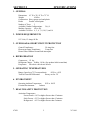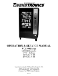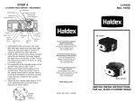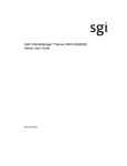
1
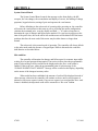
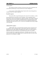
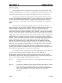
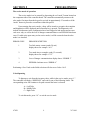
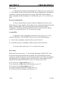
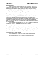
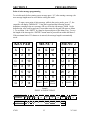
OPERATION & SERVICE
MANUAL
VC1100 SERIES: EXE-70
115 Volts, 60 Hz
67059 Software
Seaga Manufacturing, Inc. 700 Seaga Drive, Freeport IL 61032 USA
Phone: 815-297-9500 Fax: 815-297-1700
www.vendtronics.com www.seagamfg.com
A Member of the
Family of Companies.
Table of Contents
Specifications
Installation
System Overview
Operation
Programming
Wiring Diagrams
Parts
Troubleshooting
Appendix 1
67059
1
2
3
4
5
9
16
19
21
23
VC1100
SECTION 1
SPECIFICATIONS
1. GENERAL
Dimensions: 41” W x 32 1/8” D x 72” H
Weight:
650 lbs.
Construction: Heavy gauge steel and plastic
Finish:
Powder coated paint
Number of Trays:
5
Available Column Configurations: 3,4,6, 9
Machine Capacity:
60 to 450
Available Coil Sizes: 4, 5, 6, 7, 8, 10,12, and 16
2. POWER REQUIREMENTS
115 Volts, 15 Amps, 60 Hz
3. OVERLOAD & SHORT CIRCUIT PROTECTION
Control Transformer:
3/4 Amp fuse
Fluorescent Lamp Transformer
2 Amp fuse
Heated Glass Window Ground fault interrupter
4. REFRIGERATION
Compressor: 1/2 hp.
Refrigerant Charge: R404a; 1.8 lbs. (See product label on machine)
Evaporator: Forced air with electric defrost
5. OPERATING TEMPERATURES
Range: (based on a 72°F room ambient)
-20°F to +40°F
Turn On/Turn Off Differential:
Factory set for 5°F
6. ENVIRONMENT
Operating Ambient Temperature:
50°F to 100°F
Location Environment:
Indoors
7. HEALTH SAFETY PROTECTION
Activation Temperature:
Frozen Foods: +10°F or higher if more than 15 minutes
Slack Frozen: +25°F or higher if more than 15 minutes
Refrigerated: +45°F or higher if more than 5 minutes
67059
2
VC1100
SECTION 2
INSTALLATION
Upon initial receipt from the factory, allow the unit to set at room temperature for at least
24 hrs. before operation. Also, the unit should be stored vertical at all times. When
relocating the unit, it should not be tipped at extreme angles. If the unit is relocated, it is
strongly recommended that a similar 24 hr. non-operating period be observed.
If the unit was in an operating mode prior to relocation, the inside of the freezer
compartment should be allowed to rise to room temperature and completely dry out
before placing back into service.
The unit requires an independent 15 amp earth grounded circuit.
The back of the unit must be located at least 6 inches from any obstruction to ensure
proper air flow in the compressor area.
After plugging the unit into the proper wall outlet open the Service Door and turn the
main power switch on. The display on the front panel should become active after
approximately 20 seconds. Set the desired temperature on the thermostat control and
place the Refrigerator/Freezer Mode Switch in the appropriate position. When operating
in the frozen or slack frozen modes, the Glass Panel Heater switch should be in the ON
position and in the OFF position for the refrigerated mode. Please note that the resolution
of the thermostat dial setting is wider for temperatures below 0°F. It may be necessary to
make slight adjustments to achieve the desired temperature. The actual freezer
temperature can be monitored via the two-digit display located on the Vend Enable Board.
Ensure unit has reached the required temperature setting before loading product.
When the unit is used in the frozen food or slacked frozen mode of operation, all food
items should be frozen prior to stocking the unit.
67059
3
VC1100
SECTION 3
SYSTEM OVERVIEW
Refrigeration System
This system is comprised of the evaporator, condensing unit and the thermostat
control. The system becomes functional as soon as the main power switch is turned on.
Defrost System
Defrost of the evaporator is initiated by a timer every 12 hours of operation. The
defrost period lasts for approximately 21 minutes during which time the compressor is off
and the heaters in the evaporator are on. While in the defrost mode it is common to see
the temperature in the freezer compartment rise rapidly.
Vending System
Vending operations, such as, setting prices, changing the message on the front
display, accepting user selections, handling bills and coins, counting escrow balances,
making change and operating vend motors are handled by the System Control Board
which is mounted on the inside of the service door.
Vend Enable Monitoring System
The function of this system is to provide additional user protection by disabling
vending operations in the event freezer temperatures rise above a preset temperature for
an extended period of time.
Activation Temperature:
Frozen Foods: +10°F or higher if more than 15 minutes
Slack Frozen: +25°F or higher if more than 15 minutes
Refrigerated: +45°F or higher if more than 5 minutes
67059
4
VC1100
SECTION 4
OPERATION
Refrigeration Control
The temperature is thermostatically controlled and adjusted via the thermostat
which is mounted on the power panel located behind the Service Door. It is important to
remember that the compressor turns off at the thermostat setting, however, the turn on
point is based on the thermostat’s differential setting. (The differential setting as shipped
from the factory will be 5°F, however, this may be adjusted if you determine that a longer
cycling period would be more satisfactory.)
The evaporator in the ceiling of the freezer compartment has no user settings or
adjustments. The evaporator fans are activated via the Freezer Door Reset Switch, which
is mounted on the upper portion of the center wall panel. When the Freezer Door is
closed, or when the switch’s plunger is pulled out, the fans will be operational. A fan
control thermostat is mounted on the evaporator coil, that turns the fans ON at 35°F, and
OFF at 55°F. As the freezer compartment cools down from a warm temperature
condition it is normal for the fans to cycle off and on several times before reaching a stable
mode.
When operating the unit in a refrigerated mode, please keep in mind that the
temperature range is somewhat narrow (33°F to 45°F). With a differential setting of 5°F
you would be limited to adjusting the thermostat setting between 33°F and 40°F in order
to stay within the temperature boundaries.
In order to make differential adjustments, the cover to the thermostat must be
removed. If you are not familiar with this procedure, please have a trained service
technician make the initial adjustment. There are potentially dangerous voltages under this
cover and, therefore, main power to the unit should be removed before attempting
adjustments.
Defrost System
The electric defrost is automatic and is initiated by the defrost timer which is
mounted on the power panel located behind the service door. The timer runs whenever
the main power switch is on. A defrost period is initiated every 12 hours and runs for
approximately 21 minutes. During this period the compressor and evaporator fans are
turned off. Please note that it is not unusual for the temperature being displayed on the
health board to increase rather dramatically and although the food temperature is also
rising, it is doing so at a much slower rate and will remain safe for consumption.
The unit is shipped with the timer set to allow a full 12 hour period of operation
before the initial defrost period begins. The timer can be manually set at any time by
simply turning the dial in a clockwise rotation; a complete rotation represents 12 hours.
67059
5
VC1100
SECTION 4
OPERATION
System Control Board
The System Control Board controls the message on the front display, the bill
acceptor, the coin changer, the accumulation and display of escrow, the making of change
payments, keypad selection, setting of price and operates the vend motors.
Before defaulting to the sales mode of operation after powering on, the controller
will restore the vend options to their state at power off, define the motor configuration,
calculate the maximum price, reset the display and flash “—” if it takes a long time to
determine the type of changer and bill acceptor attached. If a vend was in progress at the
time of the power loss, the credit will be lost and the motor will be halted off of the home
position, therefore the next vend of this motor may be either shorter or longer than
normal.
The sales mode is the normal mode of operation. The controller will always default
to the sales mode under the absence of keypad input. While in this mode the controller
shall function as described below.
Idle condition
The controller will monitor the changer and bill acceptor for customer input while
waiting for a keypad generated interruption. If no action is taken, then the programmable
point of sales message will be scrolled on the display unless the force vend option is
enabled. If this is the case, either the programmable point of sales message or the
“PLEASE INSERT EXACT MONEY” message will be scrolled on the display, depending
on the status of the changers inventory tubes.
When credit has been established, the amount of credit will be displayed instead of
either message, otherwise the controller will continue as above until a vend sequence is
initiated or an escrow request is made. If an escrow request is received and the force vend
feature is disabled, the deposited credit will be returned in a “like coin” fashion.
67059
6
VC1100
SECTION 4
OPERATION
Coin acceptance
The controller will allow acceptance of all coins as long as the accumulated credit
is less than the maximum price of any selection in the current configuration.
Coin acceptance will be disabled during all vends, while coins are being paid out,
and while in the service mode of operation.
First bill acceptance
The first bill will be accepted if the quarter tube is above the low indicator, or if the
dime and nickel tubes are both above the low indicators. If the accumulated credit is
greater than or equal to the maximum price, then bill acceptance will be disabled. If the bill
acceptor offers escrow and acceptance is disabled because of the maximum price, the bill
will be kept in the escrow position, otherwise the bill will go straight into the bill stacker.
If the bill acceptor does not offer escrow, or bill escrow is disabled, the bill will go straight
to the bill stacker.
Additional bill acceptance
Additional bills will be accepted if the dime and quarter tubes are both above the
low indicators. If the accumulated credit is greater than or equal to the maximum price,
then bill acceptance will be disabled. If the bill acceptor offers escrow and acceptance is
disabled because of the maximum price, the bill will be kept in the escrow position,
otherwise the bill will go straight into the bill stacker. If the bill acceptor does not offer
escrow, the bill acceptor will be disabled after the second bill has been sent to the stacker
unless the Force vend feature is enabled.
67059
7
VC1100
SECTION 4
OPERATION
Selection vending
When an alpha character is depressed on the keypad, a beep will be issued while
the alpha is displayed for up to 5 seconds. If a number is depressed within that 5 seconds,
a beep will acknowledge the entry and one of the following series of events will occur:
If there has not been enough credit deposited, the selection’s character, number,
and price will be displayed for approximately 1 second with three beep tones followed by
the “PLEASE INSERT MORE MONEY” message being scrolled one time. Then the
credit, or the point of sales message if no credit has been established, will be displayed
again.
If there has been enough credit deposited (see note #1 below), the selection’s
character, number, and price will be displayed while the controller determines if the exact
amount of change can be paid to the customer. If it can not be returned, the vend
sequence is halted and the deposited credit is returned in a “like coin” fashion, three beep
tones will be issued, the “PLEASE INSERT EXACT MONEY” message will be scrolled
one time, and the idle condition of the sales mode will be resumed. If the exact amount of
change can be returned, then the selection will be vended and the amount of change will be
displayed while it is returned. If for some reason the exact amount of change cannot be
returned, as much as possible will be paid out and the remaining amount will be retained as
credit toward another vend. If the correct change is returned, the “THANK YOU”
message will be displayed for 0.8 seconds, followed by the idle condition of the sales
mode. If the motor is not allowed to complete a full cycle, or if after twelve seconds the
motor has not yet returned to a home position, the controller will beep three times while
the “MAKE ALTERNATE SELECTION” message is scrolled one time, this will be
followed by the amount of accumulated credit. If it is enabled, the force vend feature will
be overridden for approximately 25 seconds after a faulty vend.
If a selection not in the configuration, or one with a bad motor (see note #2 below)
is selected, that selection’s character, number, and price will be displayed for
approximately 1 second. Then the controller will beep three times while the “MAKE
ALTERNATE SELECTION” message is displayed one time. The credit or point of sales
message will be displayed again following the above message.
Note #1:
An item price of $0.00 is allowed as a valid vend while in the sales mode of
operation.
Note #2:
A bad motor is defined as a motor location requiring more than 12 seconds
before detecting a home position signal or an electrically open motor
circuit. Once a bad motor has been detected it can not be vended until it is
cleared by performing a free vend from within the service mode of
operation.
67059
8
VC1100
SECTION 5
PROGRAMMING
The service mode of operation
The service mode is to be entered by depressing the red “mode” button located on
the component side of the controller board. The controller automatically returns to the
sales mode if no input from the keypad is received in approximately 25 seconds or if the
“mode” button is pressed a second time within this period.
Upon entering the service mode, a beep will be issued to recognize the transition
and diagnostics will be displayed until a function key is pressed. The diagnostics will
include which motors in the configuration have been flagged as bad motors and an error
code as to why, as well as the loss of changer communications or an EEPROM checksum
error. If credit exists upon entry to the service mode, it will be restored when the sales
mode is re-invoked.
ERROR CODE
ERROR DESCRIPTION
1
Too little motor current (under 20 mA)
display shows for example “A1 1”
2
Too much time to complete vend (12 seconds)
display shows for example “C2 2”
3
Loss of changer communications display shows “ERROR 3”
4
EEPROM checksum error “ERROR 4”
Performing a Free Vend on the failed selection will clear error Codes 1 & 2.
Coin dispensing
To dispense a coin from the inventory tubes, while in the service mode, press “1”.
The controller will display “DISPENSE” and wait for one of the following letters. The
corresponding coins will continue to be paid out until the letter is released.
A = Left Tube
B = Middle Tube
C = Right Tube
To exit this mode, press “14” or exit the service mode.
67059
9
VC1100
SECTION 5
PROGRAMMING
Motor count
To display the total number of functioning motors, while in the service mode, press
“2”. The controller will test each motor drive in the current configuration to determine if a
valid motor is connected at that instant. The message “MOTORS” and the number of
motors responding will then be displayed. To exit this mode, press “14” or exit the service
mode.
Downward configuration
To remove undesired motor selections from the configuration, enter the service
mode and press “3”, the controller will reconfigure to the currently functioning motors and
display “CONFIGURED”. This is the only means of removing motors from the
configuration. This function should be performed whenever a motor has been added or
removed. To exit this mode, press “14” or exit the service mode.
Accountability
To display the stored accountability, while in the service mode, press “4”. The
controller will display “ACCOUNTING” and wait for one of the following inputs:
A = Total Cash Accountability, which will rollover after $99,999.95
B = Total Bill Acceptor Accountability), which will rollover after $99,999.00
To exit any of these modes, press “14” or exit the service mode.
Price setting
While in the service mode, press, “5”, the controller will display “SELECTION”. Enter
the desired selections letter followed by the number, these will be displayed with the
current price until the desired price is entered using the numeric keys. The most significant
digit followed by lesser significant digits. It is not necessary to enter leading zeros and
only the first four numbers will be used. Use the “10” button to enter a zero.
To save a price for a single selection, press “11”.
To save a price for an entire row of selection motors, press “12”
To save a price for the entire machine, press “13”
To cancel an unwanted setting before saving, press “14”.
To exit this mode; before entering a selection, press “14”
67059
10
VC1100
SECTION 5
PROGRAMMING
Free vend selection
To free vend a single selection motor, while in the service mode, press “6”, the
controller will display “SELECTION”. Enter the desired selection letter followed by the
number, these will be displayed with the selection price while a vend of the motor is
attempted. If the vend is successful the display will blank. If the vend is not successful the
controller will beep three times before blanking.
To exit this mode, before entering a selection, press “14” or exit the service mode.
Free vend row
To free vend an entire row of selection motors, while in the service mode, press
“7”, the controller will display “SELECTION”. Enter the letter of the desired row. The
controller will display the selections number and price as the corresponding vend is
attempted. If the vend is successful the controller will continue with the next motor. If the
vend is not successful the controller will beep three times and continue with the next
motor. This will repeat until vends on all motors in the row have been attempted, and then
the display will blank.
To exit this mode; before entering a row, press “14” or exit the service mode; after
entering a row, press “14” and hold until the current vend is completed.
Free vend entire machine
To free vend the entire machine of selection motors, while in the service mode,
press “8”, the controller will display the selections number and price as the corresponding
vend is attempted. If the vend is successful the controller will continue on with the next
motor. If the vend is not successful the controller will beep three times and continue with
the next motor. This will repeat until vends on all motors in the machine have been
attempted, and then the display will blank.
To exit this mode press “14” and hold until the current vend is completed .
The free vend by selection, row, or machine is considered as test vend
67059
11
VC1100
SECTION 5
PROGRAMMING
Point of sales message programming
To exit this mode; before starting a new message press “14”; after starting a message, the
new message length must be saved before exiting this mode
To enter a new point of sales message, while in the service mode, press “9”, the
controller will display “MESSAGE”. Using the keypad and the following keypad
definitions, entering in the new message will over write the old message. Menu 1 is the
default menu, after each keypad entry, from either menu, the keypad will return to Menu
1. To use Menu 2, the “SHIFT” key must be depressed prior to the Menu 2 key. To save
the length of the message the “ENTER” button must be pressed from within the Menu 2.
If the maximum limit of 55 characters is entered, the message length is automatically
saved.
KEYPAD
MENU 1
MENU 2
A
1
8
A
G
M
S
Y
4
B
2
9
B
H
N
T
Z
5
C
3
10
C
I
O
U
0
6
D
4
11
D
J
P
V
1
7
E
5
12
E
K
Q
W
2
8
F
6
13
F
L
R
X
3
9
G
7
14
SPACE
SHIFT
BACK
SPACE
*
ENTER
$
Sample
ENJOY A SNACK TODAY
DISPLAY
KEYPAD
DISPLAY
KEYPAD
67059
E
E
N J O Y SPACE
9 4 10 7-1
G
T O D
7-B 10 D
A
A
A
A
SPACE
G
S
7-A
N
9
A C K SPACE
A C 5
G
Y SPACE SPACE SPACE SPACE SAVE
7-1
G
G
G
G
7-7
12
VC1100
SECTION 5
PROGRAMMING
Language selection
To select the message language, while in the service mode, press “10”. The
controller will display “LANGUAGE” and wait for the appropriate letter as defined
below. After the letter has been depressed, the nationality of the language selected will be
displayed. Each message affected is listed in appendix 1.
A = Italian
B = Dutch
C = Spanish / English
D = Danish .
E = English
F = French / English
G = German
Vend options
To program the vend options, while in the service mode, press “11”, the controller
will display “OPTIONS”. Pressing one of the appropriate letters as defined below will
enter into that menu, and the current ON/Off state will be displayed, pressing the same
letter again will toggle the ON/OFF state.
Bill escrow
This option will allow the last bill accepted to be returned, provided the bill
acceptor is capable of such a feature.
To access this option press the letter “A” after the “11”. The current on/off state
will be displayed as “ESCROW xxx”. Pressing “A” again will toggle the on/off state.
To save & exit this mode, press “14” or exit the service mode.
Force Vend
This option will force the customer to complete a purchase once they have
deposited money of any form. If a vend is attempted and the motor fails during this vend,
the customer will be allowed to escrow the credit for up to 25 seconds, regardless of the
force vend status.
To access this option press the letter “B” after the “11”. The current on/off state
will be displayed as “F VND -xxx”. Pressing “B” again will toggle the on/off state.
To save & exit this mode, press “14” or exit the service mode.
DEFAULT SETTINGS
All vend options will be disabled
All of the prices will be set to $0.00
The point of sales message will be preprogrammed to: “ENJOY A SNACK NOW**”
The language will be set to English
67059
13
VC1100
SECTION 5
PROGRAMMING
Health Safety Monitoring System
The primary purpose of this system is to prevent the vending of products that are
or have been subjected to excessive temperatures for a specific period of time. Sensors
inside the freezer compartment constantly update the Vend Enable Board’s computer with
temperature readings to ensure the integrity of this safety feature. The freezer temperature
can be monitored via a two digit display located on the Vend Enable Board. Please note
that directly to the left of the left most digit is a red L.E.D. that, when lit, denotes when
freezer temperatures go below zero.
The Vend Enable Board is capable of monitoring freezer temperatures based on
three operating ranges:
1.
2.
3.
Refrigerated Foods (45°F or colder)
Soft Frozen or Slacked Frozen Foods (25°F or colder)
Frozen Foods (10°F or colder)
The particular range is selected via a miniature two position slide or rocker switch
located at approximately the center of the board (See illustration below). Each switch
section has only two positions, OFF and ON. The various switch setting combinations
determine which temperature range the computer will be monitoring. The various
combinations for ranges are:
Switch #1
OFF
OFF
ON
ON
Switch #2
OFF
ON
OFF
ON
Range
Frozen
Slacked Frozen
Refrigerated
Used for factory test
In order to maintain proper health safeguards and unit operation, you must ensure
the Vend Enable Board’s range switch is set to correspond with the desired freezer
temperature operating range.
Associated with the Vend Enable Board is an interlock switch, referred to as the
Freezer Door Reset Switch, which is mounted on the upper portion of the center wall
panel. Whenever the Freezer Door is opened and subsequently closed, the switch
initializes a timer that allows a sixty minute period to elapse before the board’s computer
starts monitoring the freezer temperature for abnormal operation. This time period
ensures there will be ample time for restocking of the trays. Also, the computer creates a
similar time delay immediately following the defrost cycle to ensure the freezer has time to
recover to its normal operating temperature.
67059
14
VC1100
SECTION 5
PROGRAMMING
Health Safety Monitoring System (continued)
When a power outage or a unit malfunction occurs which allows the freezer
temperature to rise above preset limits for a specific period of time, the front panel display
will become blank and the board’s temperature display will flash alternately between the
letters H-H or H-I and the current temperature inside the freezer. The H-H signifies that
the freezer temperature had gone above the maximum limit for refrigerated food of 45°F
for a time period greater than 5 minutes. The H-I indicates the temperature had risen
above the upper limit of either the frozen or slack frozen operating range and was above
this limit for a period greater than 15 minutes
When the unit is initially powered-up, or if a power outage occurs for a period
greater than four hours, the display will alternate between the letters OP and the current
cabinet temperature.
When any of these conditions occur all vending functions will be disabled. This
intentional interruption is to allow the operator an opportunity to determine the reason for
the abnormal freezer temperature and to likewise examine the quality of the food
products. The system can be reset to again perform all vending functions as well as
restoring the front panel display by performing a vend reset. To initiate a reset simply open
the Freezer Door for approximately 5 seconds and close again. A good indication that a
reset has occurred is the sound of the bill acceptor restarting.
67059
15
VC1100
SECTION 6
WIRING DIAGRAMS
Controller
67059
16
VC1100
SECTION 6
WIRING DIAGRAMS
Vend Enable Board
.O..P.
.H..I .
.H..H.
.9..2.
67059
17
VC1100
SECTION 6
WIRING DIAGRAMS
115 Vac/ 60Hz SCHEMATIC
67059
18
VC1100
SECTION 6
PART NO.
DE727
DE728
EL734
EL848
EL836
EL851
EL761
EL850
EL742
EL801
EL803
EL812
EL806
FA754
FA763
FA778
GL720
HA247
PL339
PL724
PL730
PL743
RE724
RE726
RE739
RE745
RE747
RE748
RE749
RE753
RE756
SA166
ST750
ST768
ST781
ST801
ST802
WF720
WF721
WF722
WF723
WF724
WF728
WF729
WF730
WF734
WF736
67059
PARTS
DESCRIPTION
LABEL,TRAY,PROD PRICING
LABEL,TRAY,PRODUCT LOCATION,A1-K9
DISPLAY BOARD
DISPLAY CABLE
COIN ACCEPTOR CABLE
BILL VALIDATOR CABLE
LAMP,35W PHILLIPS
TRANSFORMER
TRAY CABLE
VEND MOTOR
VEND ENABLE BOARD
CONTROLLER,70 EXE,67059
KEYPAD,70EXE,0-14
MOTORMOUNT,RUBBER STOPPERS
TRAY DIVIDER LOCK,RUBBER
PIN,CLEVIS,VEND MOTOR MOUNT, ALUMINUM
GLASS,3 PANE HEATED
T-HANDLE
SHAFT ADAPTER,VEND MOTOR
LINER,TRAY,7.75INCH,3 COLUMN TRAY
RETAINER HUB,VEND MOTOR
PRODUCT PUSHER,COIL,LARGE,BLACK
EVAPORATOR,1600BTU,115V
EXPANSION VALVE,1/4TON,ADJUSTABLE
MOTOR,FAN,COND,1/2HP,115V,TEC
THERMOSTAT, HEAT LIMITER (2 WIRES)
THERMOSTAT, FAN DELAY (3 WIRES)
MOTOR,FAN, EVAP, 115V
TIMER,DEFROST,115V,GEMLINE
THERMOSTAT,JOHNSON CONTROLS
COMPRESSOR, 1/2 HP, 115Vac, R404a,
COIN RETURN ASSEMBLY
DIVIDER,TRAY,VC1100
COIN OVERFLOW BOX
PLUNGER,COIN RETURN
COIN RETURN DOOR
COIN RETURN CUP
COIL,LEFT HAND,10VEND,2.50DIA
COIL,LEFT HAND,10VEND,3.00DIA
COIL,LEFT HAND,8VEND,3.00DIA
COIL,LEFT HAND,6VEND,3.00DIA
COIL,LEFT HAND,4VEND,3.00DIA
COIL,LEFT HAND,5VEND,3.00DIA
COIL,LEFT HAND,8VEND,2.50DIA
COIL,LEFT HAND,7VEND,3.00DIA
COIL,LEFT HAND,12VEND,3.00DIA
COIL,LEFT HAND,16VEND,3.00DIA
19
VC1100
SECTION 6
PARTS
Tray Adjustment
Each tray has column divider slots which are numbered to provide an even number
of spaces across the width of the tray. You may position a motor anywhere deemed
necessary to accommodate a particular package geometry, however, centered within the
column spacing is the normal position.
Motors can be added, removed or re-positioned by following the below procedure
while referring to the tray diagrams.
1.
To move a motor to a new position, remove the rubber retainer from the motor
mounting pin and from the column divider locking bar. Remove the appropriate column
divider and move the motor to its new location, insert the mounting pin, position divider
locking bar and re-apply rubber retainers.
2.
To remove motors follow step 1 and also disconnect the connector located at the
back of the motor — (CAUTION: Do not pull on the connector wires to remove the
connector from the mating plug but, rather, clasp the sides of the connector.) Disengage
the coil drive wheel from the motor by pulling straight outward on the front of the coil.
3.
When installing additional motors attach the next numbered connector from the
spare connectors located at the back of the tray.
Note: Refer to the specific manufacturer’s troubleshooting guide for the coin changer and
bill acceptor.
67059
20
VC1100
SECTION 7
TROUBLESHOOTING
Message Display on Front Panel Not Lit but Compressor Runs.
1.
2.
3.
4.
5.
6.
Vend Enable Board interrupted vend functions as a result of high freezer
temperatures.
Freezer Door is open but Reset Switch’s plunger is not pulled out.
Transformer fuse blown.
Vend Enable Board defective.
Display Board defective.
System Control Board defective.
Selection Will Not Vend.
1.
2.
3.
4.
Product jammed.
Tray or motor connector unplugged or faulty connection.
Bad motor.
System Control Board defective.
Multiple Vends from One Coil.
1.
2.
3.
Ice build-up on the cam or switch at the back of the motor.
System Control Board defective.
Defective motor switch.
More than one coil spins simultaneously
1.
2.
Damaged or worn tray cable
Poor connection at motor interface board
Unit Will Not Accept Money.
1.
2.
3.
4.
5.
6.
7.
67059
All prices are set to zero.
Will not accept bills if coins in coin changer below minimum.
Will not accept more than one bill if bill equals or exceeds the highest
priced item.
No power to System Control Board.
Vend Enable Board defective.
Coin mechanism or bill acceptor defective.
Unit must be in the Force Vend mode to accept more than two bills.
21
VC1100
SECTION 7
TROUBLESHOOTING
Improper or No Change.
1.
2.
3.
4.
5.
Out of coins.
Bent coins or slugs in coin acceptor.
Vend Enable Board defective.
Coin mechanism defective.
System Control Board defective.
Compressor Does Not Run When Main Power Switch is Turned On.
1.
2.
3.
4.
5.
Unit not plugged in wall outlet.
Defrost timer currently in defrost mode.
Building circuit breaker tripped.
Defective compressor.
Significant loss of refrigerant gas.
Freezer Will Not Cool to Operating Temperature.
1.
2.
3.
4.
5.
Dirty condenser filter.
Dirty condenser.
Evaporator fan not working. Ensure freezer door interlock switch is
functioning.
Air leakage.
Loss of refrigerant gas.
Very Rapid Rise in Freezer Temperature.
1.
67059
Unit in defrost mode.
22
VC1100
APPENDIX 1
LANGUAGES
The following messages will be affected by the language selection and will be
stored in the controller memory to be displayed as described in section 5.
English: "PLEASE INSERT EXACT MONEY"
Italian: "PER FAVORE INTRODURRE I PRECISI SOLDI"
Dutch: "AFGEPAST GELD IN WERPEN"
Spanish: "POR FAVOR DEPOSITE CANTIDAD EXACTA PLEASE INSERT
EXACT MONEY"
Danish: "INDKAST AFTALTE PENGE"
French: "FAITES L'APPOINT PLEASE INSERT EXACT MONEY"
German: "ABGEZAHLTES GELD EINWERFEN"
English: "PLEASE INSERT MORE MONEY"
Italian: "PER FAVORE INTRODURRE PIU SOLDI"
Dutch: "MEER GELD IN WERPEN"
Spanish: "POR FAVOR DEPOSITE MAS DINERO PLEASE INSERT MORE
MONEY"
Danish: "INDKAST FLERE PENGE"
French: "MONTANT INSUFFISANT INTRODUISEZ D'AUTRES PIECES
PLEASE INSERT MORE MONEY"
German: "MEHR GELD EINWERFEN"
English: "MAKE ALTERNATE SELECTION"
Italian: "FARE UNA ALTRE SCELTA"
Dutch: "ANDERE KEUZE MAKEN"
Spanish: "SELECCIONE OTRO PRODUCTO MAKE ALTERNATE SELECTION"
Danish: "VAELG ANDEN VARE"
French: "FAITES UNE AUTRE SELECTION MAKE ALTERNATE SELECTION"
German: "ANDERE WARE WAHLEN"
English: "PLEASE CALL SERVICE"
Italian: "PER FAVORE CHIAMARE SERVIZIO"
Dutch: "SERVICEDIENST BELLEN"
Spanish: "POR FAVOR LLAMAR MANTENIMIENTO PLEASE CALL SERVICE "
Danish: "TILKALD SERVICEMONTOR"
French: "DEMANDEZ LE RESPONSABLE PLEASE CALL SERVICE "
German: "BITTE KUNDENDIENST RUFEN"
English: "THANK YOU"
Italian: "GRAZIE"
Dutch: "DANK U"
Spanish: "GRACIAS"
Danish: "TAK"
French: "MERCI"
German: "VIEL. DANK"
67059
23
VC1100
APPENDIX 1
67059
LANGUAGES
24
VC1100