1
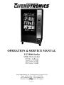
OPERATION & SERVICE MANUAL
VC1100 Series
MDB-120 Controller
67196-1 Software
120 Volts, 60 HZ
230 Volts, 50 HZ
Seaga Manufacturing, Inc. 700 Seaga Drive, Freeport IL USA
Phone: 815-297-9500 - Fax: 815-297-1700
www.vendtronics.com www.seagamfg.com
Family of Companies.
A Member of the
DE720 rev C
Table of Contents
SECTION 1 – SPECIFICATIONS
Physical characteristics
Environment
Health safety protection
Electrical and Refrigeration Characteristics
4
4
4
4
SECTION 2 - INSTALLATION
Location
Power supply connection
5
5
SECTION 3 – INITIAL SETUP
Vending
Health and Safety Range
Temperature Settings
Defrost Delay
6
6
6
6
SECTION 4 – OPERATION
Refrigeration System
Condensing unit
Evaporator
Temperature Display
Refrigeration Control system
Defrost System
System Control
Door Switch monitoring
Idle Condition
Coin Acceptance
First Bill Acceptance
Additional Bill Acceptance
DEX / UCS Data Retrieval
Vending Selection
7
7
7
7
8
8
8
8
9
9
9
10
10
10-11
SECTION 5 – PROGRAMMING
The Service Mode of Operation
Flow Chart
Diagnose
Error Codes
Motor
Count
Config
Account
Hist Sales
Hist Count
Res Sales
Res Count
Rdr Sales
Set Range
DE720 Rev. C
13
14
15
16-17
18
18
18
18
18
18
18
18
19
19
1
VC1100
Table of Contents
SECTION 5 – PROGRAMMING
Range Cash
Range Vends
Clear
Coin
Payout
Tube Fill
Uncon Accp
Exact Change
Test
Test Vend
Test Relay
19
19
19
20
20
20
20
21
22
22
23
Menu 2
Serv / Contr
Price
Items
Options
Bill Escrow
Force Vend
Max Change
Value
Multi Vend
Free Prod
Promo Vend
Default
Model
Messages
Options
24
25
25
26
26
26
26
26
27
27
28
29
29-32
33
33
Menu 3
POS / AUX
POS
Language
AUX
Time / Date
Shutdown
Temperature
Degree
Sensor 1
Sensor 2
Set Point
Delta
Health
Defrost
Discount
Autoreinstate
Can / Bottle
Optic
DE720 Rev. C
34
34
35
35
36
37-38
38
38
38
38
39
39
40
41-42
43-44
45
46
47
2
VC1100
Table of Contents
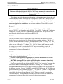
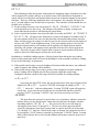
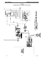
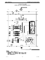
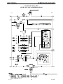
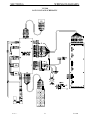
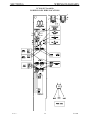
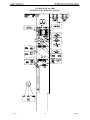
SECTION 6 WIRING DIAGRAMS
Refrigeration Interface Diagram
High Voltage Ladder Diagram 115 Vac
High Voltage Ladder Diagram 220-240 Vac
Low Voltage Schematic
Power Panel Wire Locations 115Vac
Power Panel Wire Locations 220-240Vac
Dual Coil Tray Wiring
48
49
50
51
52
53
54
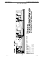
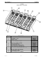
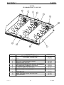
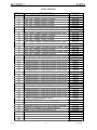
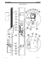
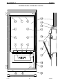
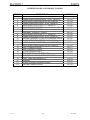
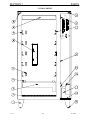
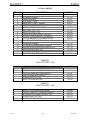
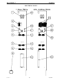
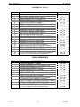
SECTION 7 PARTS
Dual Tray, 3 Column
Standard Tray 3 Column
Tray Options
Instructions for converting a 6 Column Tray to a 5 Column Tray
Condensing Unit
Evaporator
Service Door
Freezer Doors And Product Doors
VC1100 Cabinet
Electrical Panel
Cable Assemblies
SECTION 8 MAINTENANCE
68
SECTION 8 TROUBLESHOOTING
69-70
APPENDIX 1 MESSAGES
71-72
APPENDIX 2 DEX / UCS RECORD SUBSET
DE720 Rev. C
55
56
57
58
59
59
60-61
62-63
64-65
66-67
67
3
73
VC1100
SECTION 1
SPECIFICATIONS
PHYSICAL CHARACTERISTICS
•
•
•
•
•
•
•
•
•
•
Height:
Width:
Depth:
Weight:
Construction:
Finish:
Number of Trays:
Maximum Selections:
Maximum Capacity:
Available coil sizes:
72 in. / 183 cm.
41 in. / 104 cm.
32 1/8 in. / 82 cm.
650 lb
Heavy Gauge Steel
Powder Coated Paint
5
30 / 45
240 / 450
4,5,6,7,8,10,12,16
ENVIRONMENT
•
•
Operating Ambient Temperature:
Location Environment:
50°F to 100°F
Indoors only
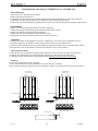
HEALTH AND SAFETY PROTECTION (Vending of products is disabled)
•
Activation Temperature:
Frozen Foods:
Slack Frozen:
Refrigerated:
None
+10°F or higher if more than 15 minutes
+25°F or higher if more than 15 minutes
+45°F or higher if more than 5 minutes
None
ELECTRICAL AND REFRIGERATION REQUIREMENTS
Power Requirements
Amperage Rating
Control Transformer
Lamp Transformer
Compressor
Refrigerant Charge
Evaporator
DE720 Rev. C
110 / 120 Vac, 60Hz
16
½ Amp fuse
2 Amp fuse
3/4 hp Hermetic
1 lb 10 oz R-404A
Forced air, Elec. Defrost
4
VC1100
SECTION 2
INSTALLATION
LOCATION
Upon receipt of the unit, inspect for any shipping damage and report directly to the
carrier. A damage report will be necessary before contacting the factory. Allow the unit to set at
room temperature for at least 24 hrs. before operation. The unit should be stored or transported
vertical at all times. When relocating the unit, it should not be tipped at extreme angles. If the
unit is relocated, it is strongly recommended that a similar 24 hr. non-operating period be
observed. If the unit was in an operating mode prior to relocation, the inside of the refrigerated
compartment should be allowed to rise to room temperature and completely dry out before
placing back into service.
The back of the unit must be located at least 6 inches from any obstruction to ensure
proper airflow in the compressor area. The system requires air to be induced from underneath the
base of the unit, through the air filter and condensing coil, and expelled out the back of the
vending machine.
POWER SUPPLY CONNECTION
CAUTION: DO NOT USE AN EXTENSION CORD
The 110 / 120 Vac unit requires an independent 20-amp earth grounded circuit.
To insure safe operation of the VC1100, the power supply must be a properly grounded
and a polarized outlet must be used. Before plugging the VC1100 into the outlet, test the outlet to
confirm it will meet the VC1100 power requirements. If the power requirements are not met,
contact a Licensed Electrician and have any necessary corrections made. After connecting to the
wall outlet, open the Service Panel and turn the main power switch on. The display on the front
panel should become active after approximately 20 seconds.
DE720 Rev. C
5
VC1100
SECTION 3
INITIAL SETUP
Upon placement of the machine on location, the following programming should be setup
to insure proper operation of the VC1100. Please verify the unit has reached the desired
temperature settings before loading product.
The temperature may be viewed at any time by pressing the “0” button on the keypad.
VENDING
Vending operations, such as, setting prices, changing the message on the front display,
handling bills, coins, credit, making change, and operating vend motors should be tested before
loading product into the machine.
(Refer to Section 5 for programming instructions)
HEALTH AND SAFETY RANGE
The function of this system is to provide additional user protection by disabling vending
operations, “PLEASE CALL SERVICE” will be displayed if the air temperature inside the
refrigerated space rises above the selected setting for a preset period of time.
Proper Health and Safety settings must be set for proper operation.
Frozen Foods:
Slack Frozen:
Refrigerated:
None:
+10°F or higher if more than 15 minutes
+25°F or higher if more than 15 minutes
+45°F or higher if more than 5 minutes
None:
A magnetic switch is located at the top of the glass door that will provide an additional 60
minutes whenever the service door is opened, an additional 15 minutes will also be provided
whenever a defrost cycle occurs.
TEMPERATURE SETTINGS
Temperature settings can be programmed for Degrees Fahrenheit or Degrees Celsius. The
Set Point can be programmed to maintain a desired temperature. A minimum 6°F / 14°C delta is
recommended to prevent short cycling and extend the life of the Compressor.
The temperature may be viewed at any time by pressing the “0” button on the keypad.
DEFROST DELAY
This option is only necessary if the customer would like the machine to defrost at a
specific time. This option allows the user to set the starting point for the first defrost cycle. When
a power loss to the Control Board has occurred, 12 hours of operation will be resumed from the
moment power was restored, before defrosting.
DE720 Rev. C
6
VC1100
SECTION 4
OPERATION
REFRIGERATION SYSTEM
The system is comprised of an Evaporator, Condensing Unit, and Electronic Control
System. The refrigeration system will shut down whenever the glass door is opened. The System
Control Board regulates all refrigeration functions, the temperatures can be adjusted by entering
the service mode and inputting the desired set point and delta temperature settings. In the event
of a Control Board failure, the Refrigeration system will run continuously, and will not cycle off
until the Control Board is repaired or replaced.
The Evaporator removes heat from the air in a refrigerated space and transfers the heat to
the liquid Refrigerant. The liquid Refrigerant evaporates and is pumped out by the Compressor
through the larger diameter tubing. The Compressor pumps the low-pressure vapor into the
Condensing Coil where it gets rid of the heat and condenses into a high-pressure liquid. The
high-pressure liquid travels through the smaller diameter tubing to the T.E.V. ( Thermostatic
Expansion Valve). The T.E.V. controls the amount of refrigerant supplied to the Evaporator, and
the cycle is repeated.
The temperature can be viewed at any time by pressing the “0” symbol on the keypad.
CONDENSING UNIT
The VC1100 uses a 3/4 hp Tecumseh Condensing Unit. It is located on the base of the
cabinet and can be accessed from the back of the unit. It consists of a Compressor, Condensing
Coil, Fan, Liquid Receiver, Starting Relay, Start Capacitor, Run capacitor, and a Thermal
Overload Protection Device. Two service ports are provided for a Qualified Service Technician
to diagnose and repair the Refrigeration System.
EVAPORATOR
The VC1100 uses a low Temperature, Forced Air, and Electric Defrost Evaporator. Each
consists of an Evaporating Coil, Thermostatic Expansion Valve, Evaporator Fan, ¼ ton TEV,
and a Heating Element. They are located inside each of the refrigerated spaces at the top
WARNING:
UNAUTHORIZED ADJUSTMENT OF THE THERMOSTATIC
EXPANSION VALVE WILL VOID THE WARRANTY!
TEMPERATURE DISPLAY
The temperature sensor readings can be displayed by pressing “0” in the sales mode of
operation.
DE720 Rev. C
7
VC1100
SECTION 4
OPERATION
REFRIGERATION CONTROL SYSTEM
The following sequence describes a typical Refrigeration Control cycle.
Upon initial power up, both compartments will begin to cool down.
1. The air temperature inside the refrigerated space cools down to the Cut-Out setting.
2. The Control Board receives a signal form the Temperature Sensor.
3. The Control Board energizes a 24Vdc Refrigeration Relay and opens the Normally Closed
Contacts.
4. The Compressor shuts off, Evaporator Fans continue to run.
5. The system remains off until the air temperature inside the refrigerated space warms up to the
Cut-In setting.
6. The Control Board receives a signal From the Temperature Sensor.
7. The Control Board de-energizes the Refrigeration Relay and closes the Normally Closed
Contacts.
8. The Compressor starts up and the cycle is repeated until the unit goes into defrost.
DEFROST SYSTEM
The Control Board controls the timing of the defrost cycle. The Control Board will
simultaneously energize a Defrost Relay, and the Refrigeration relays. When the Defrost Relay is
energized, the Normally Closed Contacts open and shut off the Compressor and Evaporator fans,
the Normally Open Contacts close and turn the Defrost Heaters on. The electric defrost is
automatic and will be initiated every 12 hours. The on time will be approximately 21 minutes.
During this period the compressor and evaporator fans are turned off. Whenever power to the
Control Board is removed, the Refrigeration will run for a full 12 hrs. before a defrost period
begins. The Defrost Start Time, duration, and period can be programmed from within the service
mode of operation.
SYSTEM CONTROL
The MDB-120 Selection System Control Board controls the message on the front
Display, Bill Acceptor, Coin Changer, Accumulation and Display of Escrow, Issuing Change
Payments, Keypad Selection, Vending of product, Price Settings, Health Safety, and
Refrigeration Control Functions.
The Sales Mode is the normal mode of operation. The controller will always default to
the sales mode under the absence of other inputs.
DOOR SWITCH MONITORING
Both of the door switches will be monitored at all times, if an open to close transition is
detected then all health safety related errors, timers, and sold out errors will be reset.
If either glass door is opened the refrigeration system will be switched off. If this open state
exceeds 30 minutes then a DOOR OPEN ERROR message will be continuously scrolled
across the display and the refrigeration system will be reactivated.
DE720 Rev. C
8
VC1100
SECTION 4
OPERATION
To protect the compressor from encountering overpressure situations due to opening and closing
the door repetitively, the controller will not re-activate the refrigeration system for a period of
1.5 minutes from the initial opening of the glass door.
IDLE CONDITION
The controller will monitor all present MDB peripherals for customer input while waiting
for a keypad generated interruption. If no action is taken, then the programmable Point of Sales
message will be scrolled on the display; provided there are sufficient coins in the coin changer.
If an adequate quantity is not detected, the “PLEASE INSERT EXACT MONEY” message will
be displayed. When credit has been established, the amount of credit will be displayed, otherwise
the controller will continue as above until a vend sequence is initiated or a Coin Return request is
made. If a Coin Return request is received and the Force Vend feature is disabled, the deposited
credit will be returned in a “like coin” fashion.
COIN ACCEPTANCE
The controller will allow acceptance of all coins as long as the accumulated credit is
equal to or less than the maximum price of any selection in the current configuration. When
Multivend is active then this maximum value increases to 3 times the highest priced selection in
the machine. Coin acceptance will be disabled during all vends, while coins are being paid out,
and while in the service mode of operation, and if card reader credit is established.
FIRST BILL ACCEPTANCE
The first bill will be accepted if the quarter tube is above the low indicator or if the dime
and nickel tubes are both above the low indicators. When accumulated credit is greater than or
equal to the maximum price, additional bill acceptance will be prevented. When multivend is
active then this maximum value increases to 3 times the highest priced selection in the machine.
If the bill acceptor offers escrow and acceptance is disabled because of the maximum price, the
last bill inserted will be kept in the escrow position, otherwise the bill will go straight into the
bill stacker. If the bill acceptor does not offer escrow, or bill escrow is disabled, the bill will go
straight to the bill stacker. The bill will be accepted if the coin tubes total cash amount is
greater than or equal to the established credit plus the additional bill value. If credit is
established from a card reader, no bills will be accepted.
DE720 Rev. C
9
VC1100
SECTION 4
OPERATION
ADDITIONAL BILL ACCEPTANCE
Additional bills will be accepted if the dime and quarter tubes are both above the low
indicators. If the accumulated credit is greater than or equal to the maximum price, additional bill
acceptance will be disabled. When multivend is active then this maximum value increases to 3
times the highest priced selection in the machine. If the bill acceptor offers escrow, and
acceptance is disabled because of the maximum price, the last bill inserted will be kept in the
escrow position. If the bill acceptor does not offer escrow, or bill escrow is disabled, the bill will
go straight to the bill stacker and the bill acceptor will be disabled after the second bill has been
sent to the stacker.
DEX / UCS Data Retrieval
DEX / UCS data retrieval is only allowed in the sales mode of operation. The retrieval
device initializes the data retrieval after it has been properly connected to the DEX port. Refer to
page 73 for the available DEX fields.
DE720 Rev. C
10
VC1100
SECTION 4
OPERATION
VENDING SELECTION
The controller responds to keypad selections from two possible sources. One
source is the 120 Select controller's own keypad and the other source is a selection
received from an MDB USD peripheral by the 120 Select Controller.
Following reception of any keypad selection, the controller will then calculate a
checksum of the MIS and pricing information. The resulting checksum will then be
compared to the previous checksum calculated when the controller last changed a MIS
or price location.
If the two checksums are different, the vend will not be allowed. This same checksum
error will cause the controller to return any deposited credit in a "like coin" fashion.
If the two check sums are identical, then the selection's character, number, and price
will be displayed while additional checks on the selection are made in the following
order.
1) Passes Health and Safety rules
2) Item is not in Shutdown range of the 'Timed Shut Down Intervals' feature
3) Item is in the configuration and it does not contain a bad motor
4) Deposited credit is greater than or equal to the price of the selection
If the selection fails any of these checks then the vending attempt will be aborted.
The controller will continue to display the selection's character, number, and price for a
period of 1 second. This is followed with three beeps from the speaker along with the
one-time scroll of a failure dependent message.
•
•
•
If the item failed the shutdown check then this scrolled message will be
"VENDING OPERATION TO RESUME AT hh.mm “.the deposited money will be
automatically returned to the customer.
If check #4 failed then this message will be "PLEASE INSERT MORE MONEY".
For the other failures, "MAKE ALTERNATE SELECTION" will be the message.
The credit or the point of sales message (if no credit has been established) will
be displayed again following the message.
If the selection has passed all of the previous checks, the controller will
determine if the exact amount of change can be paid to the customer.
The vending sequence will be halted if the controller determines that exact
change can not be returned. The controller will return the deposited credit in "like coin"
fashion. The controller will issue three beep tones along with one scroll of the PLEASE
INSERT EXACT MONEY" message and then return to the idle condition of the sales
mode. If a Promotional item (in response to purchase of another item) failed to vend, the
vend is considered good. The failed motor is flagged and displayed in service mode.
DE720 Rev. C
11
VC1100
SECTION 4
OPERATION
If all previous checks have passed then a vend of the selection will be attempted.
A successful vend results in a display of the amount of change while it is returned
using a "least coins" algorithm. If the correct change is returned, the "THANK YOU"
message will be displayed for 0.8 seconds, followed by the idle condition of the sales
mode. If for some reason the exact amount of change cannot be returned, as much as
possible will be paid out and the remaining amount will be retained as credit toward
another vend. An item price of $0.00 is allowed as a valid vend while in the sales mode
of operation.
When a vend fails, the controller will beep three times while the "MAKE
ALTERNATE SELECTION" message is scrolled one time. This will be followed by the
amount of accumulated credit. When the force vend feature is enabled, faulty vends will
result in an override of the force vend feature. Force vend will stay overridden until the
customer has attempted to escrow the credit or vended another product.
For those failed vend attempts of motors connected to the 120 Select controller,
if the motor is not allowed to complete a full cycle, or if after twelve seconds the motor
has not yet returned to a home position, the vend will be considered a failure.
A bad motor is defined as:
1) A motor location requiring more than 12 seconds before detecting a home
position signal
2) An electrically open motor circuit at the time the controller first attempts to vend
the motor.
If a configured motor not in the autoreinstate range has been detected as being
bad due to the detection of an open circuit, that motor can not be vended until it is
cleared by performing a successful free vend from within the service mode of operation.
When the optics mode is enabled and autoreinstate is inactive for the particular
selection but the optical sensor detects no product. In this case, the controller will flag
the item with a sold out error (VMC 9) in addition to a long vend error (VMC 2). The
controller will also prevent further attempts to vend the particular selection until the
selection's sold out error status is cleared.
DE720 Rev. C
12
VC1100
SECTION 5
PROGRAMMING
THE SERVICE MODE OF OPERATIONS
To enter the Service Mode press the red button located on the controller board. The
controller automatically returns to the sales mode if no input from the keypad is received in
approximately 25 seconds, or if the button is pressed a second time within this period. If credit
exists upon entering the service mode, it will be restored when the sales mode is re-established.
At the time of initial entry into and final exit from the service mode, the controller will
briefly power all currently configured motors to determine if an open circuit condition exists.
Any configured motor that exhibits an open circuit during this process will be immediately
removed from the vending machine configuration. This means that a motor previously tagged
bad in the sales mode due to an open circuit condition, and presently found to have an open
circuit condition upon entry to the service mode, will not be flagged as bad in the diagnostics
service mode menu.
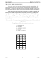
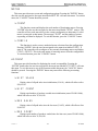
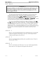
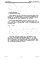
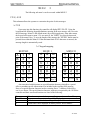
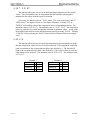
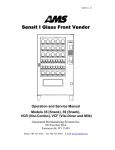
For the remainder of the programming section the following commands will be used in place of
keypad buttons
5 keypad buttons will be used to navigate the service menu
A = SCROLL UP
B = ENTER
C = SCROLL DOWN
D = SAVE
E = EXIT / CANCEL
A
B
C
D
E
F
J
DE720 Rev. C
1
3
5
7
9
G
K
2
4
6
8
0
H
L
13
VC1100
SECTION 5
DE720 Rev. C
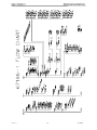
PROGRAMMING
14
VC1100
SECTION 5
PROGRAMMING
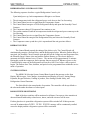
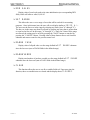
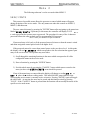
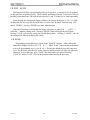
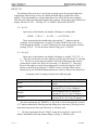
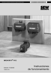
DIAGNOSE
The Diagnostics menu item displays the current status of the controller and peripherals.
Pressing “ENTER” after the user has navigated to the menu item labeled DIAGNOSE starts
this function. Upon entry the status of the controller and each of the peripherals will be checked.
The order of checking is the Vending Machine Controller, the Changer, the bill Validator, and
the card reader. The display will show in that order "VMC", "CHANGER", "VALIDATOR",
and "READER". If no problems are encountered with the individual device then the name of the
device will be followed by "OK". If problems are encountered then the device name will be
followed by an error code.
In the case of the Vending Machine Controller, it's possible that a sequence of error codes
could follow the "VMC" display if multiple errors are found with that device. The diagnostics
for the VMC will include an error code if any motor in the configuration has been flagged as
bad. In addition, the error code for the bad motor will indicate why.
A definition of all possible error codes is shown in the table below. This function may
be exited at any time by pressing the "CANCEL" button.
ERROR CODE
VMC 1
VMC 2
VMC 4
VMC 5
VMC 6
VMC 7
VMC 8
VMC 9
CHANGER 3
VALIDATOR 7
READER 8
DE720 Rev. C
ERROR DESCRIPTION
Too little motor current (under 20mA).
For an example, the display will show "VMC A1 1"
Too much time to complete vend (12 seconds).
For an example, the display will show "VMC C2 2"
NOVRAM checksum error. The display would read "VMC
Health & safety error on temperature sensor 1.
The display would read "VMC 5".
Health & safety error on temperature sensor 2.
The display would read "VMC 6".
The door is still open after 30 minutes "VMC 7".
Eyes on the activated optical sensor are blocked.
Selection was not detected by optical sensor and, as such, is
considered sold out. ).
For an example, the display will show "VMC A1 9"
Loss of changer communications or no changer.
The display would show "CHANGER 3".
Loss of bill validator communications or no bill validator.
The display would read "VALIDATOR 7"
Loss of card reader communications or no card reader.
The display would read "READER 8"
15
4"
VC1100
SECTION 5
PROGRAMMING
ERROR CODES
Enter the service mode by pressing the red button on the controller, a beep will be issued
to recognize the transition and “DIAGNOSE” will be displayed until a function key is pressed.
Press the letter “B” to enter the diagnostics menu. The diagnostics routine will present various
error codes relating to the nature of a fault condition
VMC 1
If any previously configured selection motor has become disconnected, the Control Board
will display VMC 1 after entering the Diagnostics Mode. A successful Test Vend of the selection
will clear this Error.
VMC 2
If any selection becomes jammed, turns too slow, or the home switch on the motor does
detect the home position, the Control Board will display a VMC 2. A successful Test Vend of the
selection will clear this Error.
VMC 4
A NOVRAM checksum error indicates that "some" configuration information has
changed erroneously. Configuration information consists of prices and all option settings
including health safety and temperature settings. When the error occurs, the controller does not
know what information changed, just that "some" information changed. It could be a single
location or all locations. Your customer must go in and manually check all settings to insure the
controller will function, as they want it to. This error will be cleared upon exiting the Service
Mode of Operation. Power surges are the most likely cause of a VMC 4 message
VMC 5
A VMC 5 Error indicates that Sensor 1 air temperature in the left refrigerated space has
risen above the Health and Safety setting selected by the user. All vending functions within a
selected range of rows will be disabled and “PLEASE CALL SERVICE “ will be displayed.
This Error will be cleared upon exiting the Service Mode of operation.
•
•
•
•
Frozen Foods:
Slack Frozen:
Cold:
None:
+10°F or higher if more than 15 minutes
+25°F or higher if more than 15 minutes
+45°F or higher if more than 5 minutes
None
VMC 6
A VMC 6 Error indicates that Sensor 2 air temperature in the right refrigerated space has
risen above the Health and Safety setting selected by the user. All vending functions within a
selected range of rows will be disabled and “PLEASE CALL SERVICE “ will be displayed. This
Error will be cleared upon exiting the Service Mode of operation.
DE720 Rev. C
16
VC1100
SECTION 5
PROGRAMMING
VMC 7
A VMC 7 error indicates that the reset switch at the top of the glass door has remained
open for more than 30 minutes. This error will be cleared upon exiting the service mode of
operations.
VMC 8
A VMC 8 error indicates that the optical sensor is blocked, the lens is dirty, faulty sensor,
or the connector on header P8 is disconnected. This error cannot be cleared until the problem is
resolved.
VMC 9
A VMC 9 error indicates that the optical sensor did not detect product. These errors will
be automatically cleared by either opening and closing the glass door or exiting the service
mode.
CHANGER 3
If the Coin Changer becomes disconnected from the Control Board, (i.e. Broken wire,
Faulty Control Board, or Faulty Coin Changer) CHANGER 3 will be displayed. This Error
cannot be cleared until the source of the problem is repaired. If the VC1100 uses a Debit Card
Reader without a Coin Changer or Bill Acceptor, CHANGER 3 will always be present and
cannot be cleared, this is normal
VALIDATOR 7
If the Bill Validator becomes disconnected from the Control Board, (i.e. Broken wire,
Faulty Control Board, or Faulty Bill Validator) VALIDATOR 7 will be displayed. This Error
cannot be cleared until the source of the problem is repaired. If the VC1100 uses a Debit Card
Reader without a Coin Changer or Bill Acceptor, VALIDATOR 7 will always be present and
cannot be cleared, this is normal
READER 8
If the Card Reader becomes disconnected from the Control Board, (i.e. Broken wire,
Faulty Control Board, or Card Reader) READER 8 will be displayed. This Error cannot be
cleared until the source of the problem is repaired. If the VC1100 does not use a Debit Card
Reader, READER 8 will always be present and cannot be cleared, this is normal
DE720 Rev. C
17
VC1100
SECTION 5
PROGRAMMING
MOTOR
This menu provides motor count and configuration options. Pressing the "ENTER" button
after the user has navigated to the menu item labeled MOTOR will enter this menu. To exit this
menu, the "CANCEL" button should be pressed.
COUNT
This function counts and displays the total number of functioning motors. Pressing
"ENTER" after the user has navigated to the menu item labeled COUNT starts it. The
controller will test each motor drive in the current configuration to determine if a valid
motor is connected at that instant. The message COUNT and the number of motors
responding will then be displayed. To exit this function, press the "CANCEL" button.
CONFIG
This function is used to remove undesired motor selections from the configuration.
Pressing “ENTER” after the user has navigated to the menu item labeled CONFIG
starts it. The controller will reconfigure to the currently functioning motors and display
CONFIGURED. This is the only means of removing motors from the configuration.
To exit this function, press the "CANCEL" button.
ACCOUNT
This menu provides functions for displaying the stored accountability. Pressing the
“ENTER” button after the user has navigated to the menu item labeled ACCOUNT will enter
this menu. To exit this menu or any of the functions within this menu, the "CANCEL" button
should be pressed. Pressing the “ENTER” button may enter all the following accounting
functions.
HIST SALES
Display value of all paid sales since initialization (VA101), which will rollover after
$99,999.95.
HIST COUNT
Display total number of products vended since initialization (sum of PA201 fields),
which will roll over after 79,999,920
RES SALES
Display value of all paid sales since the last reset (VA103), which will rollover after
$9,999.95.
RES COUNT
Displays total number of products vended since the last reset (sum of PA203 fields),
which will roll over after 79,999,920.
DE720 Rev. C
18
VC1100
SECTION 5
PROGRAMMING
RDR SALES
Display value of total card reader sales since initialization (no corresponding DEX
field), which will rollover after $9,999.95
SET RANGE
This allows the user to set a range of rows that will be tracked for accounting
purposes. Once in this menu item, the user will see a display similar to SR/ER A-L.
The user sets the first row in the range by selecting any letter (from "A" through "L").
The last row in the range may then be selected by entering any letter that is greater than
or equal to the first row in the range ("A" through "L"). Once the 2 letters in the range
are entered, the setting may be saved by pressing the "SAVE" button or canceled by
pressing the "CANCEL" button. Pressing either of these buttons forces exit from this
submenu and returns control to the previous menu level.
RANGE CASH
Display value of all paid sales over the range defined in SET RANGE submenu
since the last reset (sum of PA204 fields in the defined range).
RANGEVENDS
Display total number of products vended over the range defined in SET RANGE
submenu since the last reset (sum of PA203 fields in the defined range).
CLEAR
This function allows the user to set all re-settable fields to 0.Upon entry into the
function, those re-settable items are cleared and the display shows CLEARED.
DE720 Rev. C
19
VC1100
SECTION 5
PROGRAMMING
COIN
This function is provided for manually filling and dispensing coins from the changer. In
addition, there are several functions for controlling credit acceptance and the display of messages
related to credit status. Pressing the “ENTER” button after the user has navigated to the menu
item labeled COIN enters this menu. To exit this menu or any of the functions within this
menu, the "CANCEL" button should be pressed. Pressing the “ENTER” button will enter all the
following coin functions.
PAYOUT
This function allows for the dispensing of coins from the inventory tubes. Upon entry
into this function the controller will display DISPENSE and wait for the user to press
one of the following numbers. The corresponding coins will continue to be paid out until
the number is released.
1 = Most significant coin
2 = Next significant coin
3 = Next significant coin
4 = Least significant coin
TUBE FILL
Upon entry into this function, the controller will first display FILL COINS.
After a short delay, the controller will change the display to show zero credit. At this
point, the operator may begin entering coins into the changer. As coins are entered the
display will note the total value of the coins entered. After returning to sales mode the
credit will be zero. This feature will be inhibited in the service mode If a credit exist from
the sales mode before entering service mode.
UNCON ACCP
The Unconditional Acceptance option forces the controller to accept any bill or
coin less than a specified value regardless of whether the changer can return an
equivalent value of credit. All coins or bills equal to or less than this specified value will
be accepted.
Upon entry to this function a five-digit number representing the current
unconditional acceptance value appears. A value up to 5 digits may now be entered using
the numeric keys. This value may be saved at any time by pressing the SAVE key. The
maximum settable value for Unconditional Acceptance is equal to the largest
denomination of currency or coin accepted by the changer or validator. If the
operator attempts to save a value that exceeds this amount, a warning message will
appear and the displayed setting will revert to this maximum value. To exit this mode,
before entering a value, press CANCEL or exit the service mode.
DE720 Rev. C
20
VC1100
SECTION 5
PROGRAMMING
EXACT CHNG
The Exact Change option forces the controller to display the message PLEASE
INSERT EXACT MONEY if a specified value of credit and every value, in
increments of the least coin tube value, less than this value cannot be paid back.
Upon entry to this function a five-digit number representing the exact change value
appears. A value of up to 5 digits may now be entered using the numeric keys. This value
may be saved at any time by pressing the SAVE key.
•
•
•
•
When the highest vend price is greater than the unconditional acceptance value, then
the maximum settable value for exact change will be 3 times the highest vend price.
When the highest vend price is less than the unconditional acceptance value then the
maximum settable value for exact change is 3 times the unconditional acceptance
value.
If the operator attempts to save a value that exceeds this amount, a warning message
will appear and the displayed setting will revert to this maximum value.
The minimum value for exact change is the unconditional accept value. If the
operator attempts to save a value less than this amount, a warning message will
appear and the displayed setting will revert to this minimum value.
To exit this mode before entering a value, press CANCEL or exit the service mode.
DE720 Rev. C
21
VC1100
SECTION 5
PROGRAMMING
TEST
This menu provides functions that allow the operator to test motors and/or relay output
control lines. Pressing the "ENTER" button after the user has navigated to the menu item labeled
TEST will enter this menu. To exit this menu or any of the functions within this menu, the
"CANCEL" button should be pressed.
TEST VEND
This menu provides functions that allow the operator to test vend either individual
motors or a range of motors. Pressing the "ENTER" button after the user has navigated to
the menu item labeled TEST VEND will enter this menu. Upon entry to the function,
the display will read SELECT
--.
To test vend a single motor the user should enter the desired selection's letter
followed by its number. To test vend a range of motors the user should enter the letter of
the first row to vend followed by the letter of the last row to vend. After entering the
selection(s), if the operator is satisfied then the "SAVE" button should be pressed to
initiate a vend attempt on the selected motor(s). If the operator is not satisfied with the
selection or if he/she wants to exit the menu then the "CANCEL" button should be
pressed and control will pass back to the higher level where TEST VEND will be
displayed once again.
When the vend process is initiated, the display will show the particular selection
followed by the price of the selection as a vend is attempted. When the vend attempt has
completed and the selection corresponded to a single selection or the last selection in a
range of selections, control will pass back to the selection display, SELECT --.
• If for any reason, a vend attempt on a particular motor fails then the controller will
signal this by beeping 3 times.
• If optical sensor is enabled, the controller will wait for 3 seconds to verify product, if
no product was detected then the controller will beep three times before attempting
the next selection in the sequence.
• During the process of test vending a range of selections, the operator may press and
hold the "CANCEL" button to cancel the process and return control to the selection
display, SELECT --.
• A successful test vend on a motor clears all errors associated with that selection.
DE720 Rev. C
22
VC1100
SECTION 5
PROGRAMMING
TEST RELAY
WARNING !!!
The operator should be aware that operations of the functions within this menu have
direct control over whatever device(s) is/are connected to those lines. With some
devices (such as compressors), there is the potential for damaging the device with
frequent toggling of this line.
This menu provides functions that allow the operator to test the operation of the
refrigeration and defrost relays. Pressing the "ENTER" button after the user has
navigated to the menu item labeled TEST RELAY will enter this menu. Upon entry
to the menu, the display will read RELAY1. By scrolling through the menu the
operator may choose 2 additional relay functions, RELAY2, and RELAY3. To enter
any of these functions the operator should press the "ENTER" button.
Upon entry to the individual relay functions, the display will change to reading ON
* or OFF * where the * indicates editing mode. This initial ON/OFF status indicates
if the corresponding relay control in is active or inactive. Pressing "ENTER" again will
toggle the on/off state. At any time, pressing the “SAVE” or “CANCEL” buttons will
exit the function. Upon exit from the function the state of the corresponding relay control
line will revert to a state that is dependent on the controller's normal relay control
algorithm.
RELAY 1
RELAY 1 is the Left Refrigeration Relay and is controlled by Sensor 1 located in the
refrigerated compartment. When Relay 1 is off, relay 1 will be energized and the
Compressor and Evaporator Fans will be off.
RELAY 2
RELAY 2 is the Right Refrigeration Relay and is controlled by Sensor 2. Relay 2 is
not used on the VC1100
RELAY 3
RELAY 3 is the defrost relay. When relay 3 is on, relay 3 will be energized and the
heaters will be on. The Compressor and Evaporator Fans will be off.
DE720 Rev. C
23
VC1100
SECTION 5
PROGRAMMING
Menu 2
The following sub-menu’s can be accessed within MENU 2
SERV/CONTR
This password accessible menu allows the operator to control which menus will appear
during navigation of the service mode. The only menus not under this control are MENU 2,
MENU3, and this menu.
The user enters this menu by pressing the "ENTER" button after navigating to the menu item
labeled SERV/CONTR. Upon entry to this menu, the controller will display PASS --- and request that the operator enter a password. The procedure for entry of the 4-character
password follows the same method used for programming POS messages.
Please contact your distributor for password HELP.
If password entry is left early or if the password entered is incorrect then the menu is exited
and menu navigation control passes back to the higher level.
If the password entered is correct then control passes to the next lower level. At this point,
the display will read DIAGNOSE which corresponds to the first selection that appears upon
entry to the service mode. The operator may now either:
1) Scroll through the remaining functions in the menu which correspond to all of the
configurable menus in the service mode
2) Enter a function by pressing the "ENTER" button
3) Exit this whole menu by pressing the "CANCEL" button which returns control to the
menu just above the SERV/CONTR menu should be pressed.
If any of the menu items are entered then the display will change to reading ON * or
OFF * where the * indicates editing mode. This initial ON/OFF status indicates if the
corresponding service menu is currently active or inactive. Pressing "ENTER" again will toggle
the on/off state. At any time the state may be stored and this function exited by pressing
"SAVE". If the "CANCEL" button is pressed then the function will not modify the status of the
specific service mode menu.
DE720 Rev. C
24
VC1100
SECTION 5
PROGRAMMING
PRICE
This menu provides functions that allow the operator to assign prices to individual selections,
over a range of selections, or to a combination of selections. Pressing the "ENTER" button after
the user has navigated to the menu item labeled PRICE will enter this menu. To exit this menu
or any of the functions within this menu, the "CANCEL" button should be pressed. Pressing the
"ENTER" button when any of the following functions are highlighted will pass control to that
function.
Note that the maximum price that can be set in all of the following cases is 199.99 for a scale
factor of 1 and 999.95 for a scale factor of 5.
ITEM (S)
Pressing the "ENTER" button after the user has navigated to the menu item labeled
ITEM (S) will enter this menu. Upon entry, the display will read SELECT--.
•
To set the price of a single selection the user should enter the letter of the selection
followed by its number. After entering the selection, the "SAVE" button should be
pressed. The selection's location will be displayed along with a 5-digit price. The desired
price should then be entered using the numeric keys starting with the most significant
digit followed by lesser significant digits. . Pressing "SAVE" will store the value and
return to SELECT-- on the display.
•
To set the price for a range of selections the user should enter the letter of the first row
followed by the letter of the last row. After entering the selections, the "SAVE" button
should be pressed. A 5-digit price will appear the display. The desired price should then
be entered using the numeric keys starting with the most significant digit followed by
lesser significant digits. . Pressing "SAVE" will store the value and return to
SELECT-- on the display.
•
Pressing the “CANCEL” button while SELECT-- is displayed will return to the
PRICE menu.
•
Pressing the “CANCEL” button while 000.00 is displayed will return to the
SELECT-- menu.
DE720 Rev. C
25
VC1100
SECTION 5
PROGRAMMING
OPTIONS
This menu provides functions that allow the operator to control a variety of vending options.
Pressing the "ENTER" button after the user has navigated to the menu item labeled "OPTIONS"
will enter this menu. To exit this menu or any of the functions or submenus within this menu, the
"CANCEL" button should be pressed. Pressing the "ENTER" button when any of the following
functions are highlighted will pass control to that function.
BILL SCROW
This option will allow the last bill accepted to be returned, provided the bill acceptor
is capable of such a feature.
Upon entering this function the display will show the current on/off state as On *
or OFF *. Pressing "ENTER" again will toggle the on/off state. Pressing "SAVE" will
store the setting and exit the menu. Pressing "CANCEL" will exit the menu without
modifying the setting.
FORCE VEND
This option will force the customer to complete a purchase once they have deposited
money of any form. If a vend is attempted on a configured selection and the motor fails
during this vend, the credit will be placed in escrow and the customer would be allowed a
credit return in a “like coin” fashion, regardless of the force vend status.
Upon entering this function the display will show the current on/off state as, On *
or OFF *. Pressing "ENTER" again will toggle the on/off state. Pressing "SAVE" will
store the setting and exit the function. Pressing "CANCEL" will exit the function without
modifying the setting.
MAX CHANGE
This option will prevent change from being returned to the customer until the credit
amount is less than or equal to the programmed maximum change limit.
Upon entering this submenu, the display will show the current On/Off State as “On”
or "OFF". At this point, the user may edit the On/off State or scroll to the "VALUE"
function using "UP" or "DOWN". Either function may be entered by pressing "ENTER".
If the on/off function is entered then the display will appear as either ON * or OFF *
where the * indicates editing mode. Pressing "ENTER" again will toggle Maximum
change's on/off state. Pressing "SAVE" will store the setting and exit the function.
Pressing "CANCEL" will exit the function without modifying the setting.
VALUE
Upon entering the VALUE function, the display will show the currently
programmed maximum change limit. This limit may now be modified in the same
manner as described in the price setting procedure.
DE720 Rev. C
26
VC1100
SECTION 5
PROGRAMMING
MULTI VEND
This option will allow the customer to purchase more than one product if enough
credit has been deposited. When this option is active, any credit remaining after a vend
attempt is not automatically returned. At this point, the customer has one of the
following options.
1) Making another selection if there's enough credit
2) Depositing more money
3) Coin return of escrowed credit.
If Force Vend is also active then the customer will be forced to attempt the purchase
of at least one item. If a vend is attempted on a configured selection and the motor fails
during this vend, the credit will be placed in escrow and the customer will be allowed a
credit return in a “like coin” fashion, regardless of the force vend status.
Upon entering this function the display will show the current on/off state as On *
or OFF *. Pressing "ENTER" again will toggle the on/off state. Pressing "SAVE" will
store the setting and exit the function. Pressing "CANCEL" will exit the function without
modifying the setting.
FREE PROD
This option allows a free product to be given to the customer at a preprogrammed
interval. When enabled, every nTH product will be vended at no cost, all accumulated
credit will be returned, and the message "FREE ON US" will be displayed during the
vend process. Setting this interval to '1' provides a free vend at every transaction, '0'
disables the option, and the maximum valid interval is 255. Note that determination of
free product status is made only after credit equal to or greater than the normal cost of a
product has been deposited and the customer has selected the specific product.
Upon entry into this function, the current interval will be displayed as FREE
xxx. A new interval may be entered by pressing the numeric keys, these will be
displayed as they are entered. The most significant digit followed by lesser significant
digits. It is not necessary to enter leading zeros and only the first three numbers will be
used. Pressing "SAVE" will store the setting and exit the function. Pressing "CANCEL"
will exit the function without modifying the setting.
DE720 Rev. C
27
VC1100
SECTION 5
PROGRAMMING
PROMO VEND
This function will allow a promotional product to be given to a customer for free in response
to their purchase of another product. When enabled, purchasing selection '1' from one of the two
possible promotional rows will result in both selection '1' and '2' of that row to vend sequentially.
Upon entering this submenu the display will show the current on/off state as "On " or "OFF".
At this point, the user may edit the on/off state or scroll to the "RANGE" function using "UP"
and/or "DOWN". Pressing "ENTER" may enter either function.
If the on/off function is entered then the display will appear as either ON * or OFF *
where the * indicates editing mode. Pressing "ENTER" again will toggle the on/off state.
Pressing "SAVE" will store the setting and exit the editing mode.. Pressing "CANCEL" will exit
the editing mode without modifying the setting.
RANGE
Programming promotional rows is done in the "RANGE" function. After entering this
function the display will show SR/ER X-Y. Where X and Y represent the promotional
rows to be programmed (row A, row B...etc.). Pressing the alphabetic keys may enter new
rows. The first entry will effect the center character and the second will effect the right most
character. To store the rows, press "SAVE" after both entries are entered. Pressing
"CANCEL" before "SAVE" will exit the function without storing the new rows.
DE720 Rev. C
28
VC1100
SECTION 5
PROGRAMMING
DEFAULT
This menu provides functions that allow the operator to restore some or many of the
controller's default settings. Pressing the "ENTER" button after the user has navigated to the
menu item labeled "DEFAULT" will enter this menu. Pressing the "ENTER" button when any of
the following submenus or functions are highlighted will pass control to that respective submenu
or function. Upon entry to the MESSAGES and OPTIONS functions, the controller will display
"CONFIGURED" indicating that the settings associated with the corresponding function are now
in effect. To exit any portion of this menu or any of the functions within this menu, the
"CANCEL" button should be pressed. The following 3 sections contain tables showing those
settings, which take effect when the corresponding function is selected.
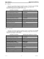
MODEL
This function allows the operator to choose a specific set of default machine settings that
correspond to the type of vending machine the 120 Select Controller will be used to control.
Upon entry into this function, the controller will display one of the machine types listed
at the top of each of the following tables along with an appended "*". The displayed
machine type represents the current machine configuration. The "*" indicates that editing
mode is active and that the operator may scroll through the available machine types via the
"UP" or 'DOWN" buttons. Pressing "SAVE" will reconfigure the default settings of the
controller to correspond to those associated with the selected type and shown in the table. In
addition, a press of the "SAVE" will force an exit from the menu. To exit the menu without
saving the selection, press "CANCEL".
The following tables list the default settings that apply to each of the different machine
types and that are applied every time a machine type is saved. Following the machine type
tables is one additional table listing those default settings that are common to all of the
machine types.
DE720 Rev. C
29
VC1100
SECTION 5
PROGRAMMING
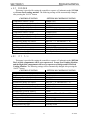
VC COLD
This menu is provided for setting the controller to operate a Vendtronics model VC1100
as a Refrigerated Fresh Food vending machine. The following settings will be
automatically changed after pressing the “SAVE” button.
CONTROL FUNCTION
Temperature Sensors 1 mode
Set point temperatures for Sensor 1
Delta temperatures for Sensor 1
Health Safety Level for Sensor 1
Health Safety Range for Sensor1
Temperature Sensors 2 mode
Set point temperatures for Sensor 2
Delta temperatures for Sensor 2
Health Safety Level for Sensor 2
Health Safety Range for Sensor2
Duration of defrost cycle
Refrigeration period
Optic Sensor mode
Point of Sales message (POS)
Refrigeration relay type
SETTING OF CONTROL FUNCTION
Enabled (ON)
36° Fahrenheit
6° Fahrenheit
COLD
Start row = "A" and End Row = "E"
Disabled (OFF)
36° Fahrenheit
6° Fahrenheit
COLD
Start row = "F" and End Row = "K"
20 minutes
12 hours
Disabled (OFF)
"ENJOY A SNACK TODAY"
Normally closed
VC SLACK
This menu is provided for setting the controller to operate a Vendtronics model VC1100
as a Slacked Frozen Food vending machine. The following settings will be automatically
changed after pressing the “SAVE” button.
CONTROL FUNCTION
Temperature Sensors 1 mode
Set point temperatures for Sensor 1
Delta temperatures for Sensor 1
Health Safety Level for Sensor 1
Health Safety Range for Sensor1
Temperature Sensors 2 mode
Set point temperatures for Sensor 2
Delta temperatures for Sensor 2
Health Safety Level for Sensor 2
Health Safety Range for Sensor2
Duration of defrost cycle
Refrigeration period
Optic Sensor mode
Point of Sales message (POS)
Refrigeration relay type
DE720 Rev. C
SETTING OF CONTROL FUNCTION
Enabled (ON)
10° Fahrenheit
6° Fahrenheit
SLACK
Start row = "A" and End Row = "E"
Disabled (OFF)
10° Fahrenheit
6° Fahrenheit
SLACK
Start row = "F" and End Row = "K"
20 minutes
12 hours
Disabled (OFF)
"ENJOY A SNACK TODAY"
Normally closed
30
VC1100
SECTION 5
PROGRAMMING
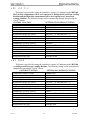
VC FROZEN
This menu is provided for setting the controller to operate a Vendtronics model VC1100
as a Frozen Food vending machine. The following settings will be automatically changed
after pressing the “SAVE” button.
CONTROL FUNCTION
Temperature Sensors 1 mode
Set point temperatures for Sensor 1
Delta temperatures for Sensor 1
Health Safety Level for Sensor 1
Health Safety Range for Sensor1
Temperature Sensors 2 mode
Set point temperatures for Sensor 2
Delta temperatures for Sensor 2
Health Safety Level for Sensor 2
Health Safety Range for Sensor2
Duration of defrost cycle
Refrigeration period
Optic Sensor mode
Point of Sales message (POS)
Refrigeration relay type
SETTING OF CONTROL FUNCTION
Enabled (ON)
-10° Fahrenheit
6° Fahrenheit
FROZEN
Start row = "A" and End Row = "E"
Disabled (OFF)
-10° Fahrenheit
6° Fahrenheit
FROZEN
Start row = "F" and End Row = "K"
20 minutes
12 hours
Disabled (OFF)
"ENJOY A SNACK TODAY"
Normally closed
Dt lft frz
This menu is provided for setting the controller to operate a Vendtronics model DT2100.
The Left Side compartment will be set to operate as a Frozen Food Vending Machine
and the Right Side compartment will be set to operate as a Refrigerated Fresh Food
Vending Machine. The following settings will be automatically changed after pressing the
“SAVE” button.
CONTROL FUNCTION
SETTING OF CONTROL FUNCTION
Temperature Sensors 1 mode
Enabled (ON)
Set point temperatures for Sensor 1
-10° Fahrenheit
Delta temperatures for Sensor 1
6° Fahrenheit
Health Safety Level for Sensor 1
FROZEN
Health Safety Range for Sensor1
Start row = "A" and End Row = "E"
Temperature Sensors 2 mode
Enabled (ON)
Set point temperatures for Sensor 2
36° Fahrenheit
Delta temperatures for Sensor 2
6° Fahrenheit
Health Safety Level for Sensor 2
COLD
Health Safety Range for Sensor2
Start row = "F" and End Row = "K"
Duration of defrost cycle
20 minutes
Refrigeration period
12 hours
Optic Sensor mode
Disabled (OFF)
Point of Sales message (POS)
"ENJOY A SNACK TODAY"
Refrigeration relay type
Normally closed
DE720 Rev. C
31
VC1100
SECTION 5
PROGRAMMING
Dt rht frz
This menu is provided for setting the controller to operate a Vendtronics model DT2100.
The Left Side compartment will be set to operate as a Refrigerated Fresh Food Vending
Machine and the Right Side compartment will be set to operate as a Frozen Food
Vending Machine. The following settings will be automatically changed after pressing the
“SAVE” button.
CONTROL FUNCTION
SETTING OF CONTROL FUNCTION
Temperature Sensors 1 mode
Enabled (ON)
Set point temperatures for Sensor 1
36° Fahrenheit
Delta temperatures for Sensor 1
6° Fahrenheit
Health Safety Level for Sensor 1
COLD
Health Safety Range for Sensor1
Start row = "A" and End Row = "E"
Temperature Sensors 2 mode
Enabled (ON)
Set point temperatures for Sensor 2
-10° Fahrenheit
Delta temperatures for Sensor 2
6° Fahrenheit
Health Safety Level for Sensor 2
FROZEN
Health Safety Range for Sensor2
Start row = "F" and End Row = "K"
Duration of defrost cycle
20 minutes
Refrigeration period
12 hours
Optic Sensor mode
Disabled (OFF)
Point of Sales message (POS)
"ENJOY A SNACK TODAY"
Refrigeration relay type
Normally closed
BV COLD
This menu is provided for setting the controller to operate a Vendtronics model BV3100
as a Refrigerated Beverage Vending Machine. The following settings will be automatically
changed after pressing the “SAVE” button.
CONTROL FUNCTION
SETTING OF CONTROL FUNCTION
Temperature Sensors 1 mode
Enabled (ON)
Set point temperatures for Sensor 1
36° Fahrenheit
Delta temperatures for Sensor 1
6° Fahrenheit
Health Safety Level for Sensor 1
COLD
Health Safety Range for Sensor1
Start row = "A" and End Row = "E"
Temperature Sensors 2 mode
Disabled (OFF)
Set point temperatures for Sensor 2
36° Fahrenheit
Delta temperatures for Sensor 2
6° Fahrenheit
Health Safety Level for Sensor 2
COLD
Health Safety Range for Sensor2
Start row = "F" and End Row = "K"
Duration of defrost cycle
20 minutes
Refrigeration period
12 hours
Optic Sensor mode
Enabled (ON)
Point of Sales message (POS)
"ENJOY A COLD BEVERAGE TODAY"
Refrigeration relay type
Normally open
DE720 Rev. C
32
VC1100
SECTION 5
PROGRAMMING
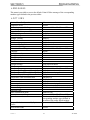
MESSAGES
This menu is provided to reset to the default Point Of Sales message of the corresponding
machine types defined in the previous tables.
OPTIONS
Service Menu Configuration
Diagnostic errors
Accounting re-settable Range
Exact change Value
Unconditional Acceptance Value
Bill Escrowing
Force Vending
Multiple Vending
Free Product
Maximum change
Maximum Change Value
Promotional Vending
Promotional Vend Range
Language
Time Hours value
Time Minutes value
Time Date value
Time Month value
Time Year value
Daylight Savings
Shutdown
Shutdown Range
Shutdown Turn-on Times (1 through 4)
Shutdown Turn-off Times (1 through 4)
Shutdown Days (1 through 4)
Temperature Unit of Measurement
Discount
Discount start time
Discount end time
Discount Days
Discount Range
Discount Value
Auto-reinstatement Mode
Auto-reinstatement Range
Optic Sensor mode
Range of Selections covered by Optic
Sensor
All resettable fields
DE720 Rev. C
All menus restored
Cleared
Start row = "A" and End Row = "K"
0
0
Enabled
Disabled
Disabled
Disabled
Disabled
20 * least coin factor
Disabled
Start row = "A" and End Row = "A"
English
0
0
1
1
0
North American Rules
Disabled
Start row = "A" and End Row = "A"
00:00 ( hours : minutes )
00:00 ( hours : minutes )
All days are turned off
Fahrenheit (F)
Disabled
00:00 ( hours : minutes )
00:00 ( hours : minutes )
All days are turned off
Start selection = "A1” End selection = "A1"
0
Disabled (OFF)
Start row = "A" and End Row = "A"
This is reset to the default setting of the
corresponding machine types defined in
the tables of the earlier default settings.
Start row = "A" and End Row = "K"
Cleared
33
VC1100
SECTION 5
PROGRAMMING
MENU
3
The following sub-menu’s can be accessed within MENU 3
POS/AUX
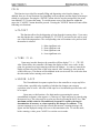
This submenu allows the operator to customize the point of sales messages.
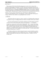
POS
Upon entry into this function, the controller will display MESSAGE. Using the
keypad and the following keypad definitions, entering in the new message will over write
the old message. Menu I is the default menu, after each keypad entry, from either menu,
the keypad will return to menu I. To use menu II, the "SHIFT" key must be depressed
prior to the menu II key. To save the length of the message the "ENTER" button must be
pressed from within the Menu II. If the maximum limit of 105 characters is entered, the
message length is automatically saved.
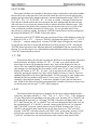
3x7 keypad mapping
KEYPAD
A
B
C
D
E
F
J
1
3
5
7
9
G
K
MENU I
2
4
6
8
0
H
L
A
B
C
D
E
F
G
H
I
J
K
L
SPACE SHIFT
MENU II
M
N
O
P
Q
R
S
T
U
V
W
X
Y
Z
0
1
2
3
BACK
SPACE
*
ENTER
4
5
6
7
8
9
$
Also associated with this menu are special function characters that allow a special
effect or machine specific information to be included in the scrolling POS message.
Entry of a special function character involves entering first a '*' character followed by
one or two letters. The special function character sequences recognized by the 120 Select
controller and their associated functions are listed in the following:
*B
*D1, *D2
*P
*T
DE720 Rev. C
When character is reached, a space will appear and controller will beep
Temperature of respective sensor will be displayed.
When character is reached, scrolling will stop for 1/2 second.
Current time will be displayed in military format "hours.minutes".
34
VC1100
SECTION 5
PROGRAMMING
LANGUAGE
This function allows the operator to choose a specific language in which sales mode
messages will be displayed.
Upon entry into this function, the controller will display one of the following nationalities
along with an appended *. The displayed nationality represents the currently activated
language. The * indicates that editing mode is active and that the operator may scroll
through the available languages via the "UP" or 'DOWN" buttons. Pressing "SAVE" will
activate the currently selected language and exit the menu. To exit the menu without saving
the selection, press "CANCEL".
ITALIAN
DUTCH
SPANISH
DANISH
ENGLISH
FRENCH
GERMAN
AUXILIARY
See appendix 2 for message translations.
If AUXILIARY is selected out of the previous list then an alternative list of operator
created sales mode messages will be used. The function that is used to create those messages
is described in the following section.
AUX
This function allows the operator to create custom messages that can be used in place of
the customer lead through messages listed in appendix 2.
Upon entry into this function, the controller will display MESSAGE 1. At this point,
pressing "UP" or "DOWN" will scroll through the 7 other messages or at any time a press of
"ENTER" will allow editing of the selected message. Editing is done in the same fashion as
the Point of Sales message. If a message is saved during editing then MESSAGE n+1
will appear on the display. After starting a new message, the message must be saved before
starting another function. Each message length limit is listed in appendix 2.
DE720 Rev. C
35
VC1100
SECTION 5
PROGRAMMING
TIME/DATE
This option will allow the operator to set the time and date for timed operations. Pressing the
"ENTER" button after the user has navigated to the menu item labeled TIME/DATE will
enter this menu. Pressing the "ENTER" button when any of the following functions are
highlighted will pass control to that function. To exit this menu or any of the functions within
this menu without saving settings, the "CANCEL" button should be pressed.
TIME
Upon entry to this function, the current time of day will be displayed in a 24 hour
format as TIME hh.mm. A new time may be entered by pressing the numeric keys.
They will be displayed as they are entered. The most significant digit followed by lesser
significant digits. It is not necessary to enter leading zeros and only the first four numbers
will be used. To store the time and exit, press "SAVE".
MONTH
Upon entry to this function, the current month will be displayed in a numeric format
as MONTH mm. A new month may be entered by pressing the numeric keys. They will
be displayed as they are entered. The most significant digit followed by lesser significant
digit. It is not necessary to enter leading zeros and only the first two numbers will be
used. To store the month and exit, press "SAVE".
DATE
Upon entry to this function, the current date (1 - 31) will be displayed in a numeric
format as DATE dd. A new date may be entered by pressing the numeric keys. They
will be displayed as they are entered. The most significant digit followed by lesser
significant digit. It is not necessary to enter leading zeros and only the first two numbers
will be used. To store the date and exit, press "SAVE".
YEAR
Upon entry to this function, the current year will be displayed in a numeric format as
YEAR yy. A New Year may be entered by pressing the numeric keys, these will be
displayed as they are entered. The most significant digit followed by lesser significant
digit. It is not necessary to enter leading zeros and only the first two numbers will be
used. To store the year and exit, press "SAVE".
DE720 Rev. C
36
VC1100
SECTION 5
PROGRAMMING
SHUTDOWN
This option will allow the controller to shut down a range of selections or the entire machine
based on four time of day intervals. If the time falls within one of these intervals and the entire
machine has been selected for shutdown then the customer lead through message VENDING
OPERATION TO RESUME AT hh.mm is scrolled. If a range of selections has
been chosen for shutdown that does not encompass the entire machine then the same message
will scroll once for every time the customer makes a selection that falls within the range. Note
that for each time of day interval, the customer can select from no days up to every day of the
week on which the specified time intervals will be active. For any given day these 4 time
intervals may overlap one another. Pressing the "ENTER" button after the user has navigated to
the menu item labeled SHUTDOWN accesses this option.
Upon entry to the SHUTDOWN menu, the current on/off state of the shutdown option will
be displayed as ON or OFF. A press of "ENTER" will change the display to ON * or OFF
* where the * indicates editing mode. Pressing "ENTER" again will toggle the on/off state.
At any time the state may be stored and this function exited by pressing "SAVE". Pressing the
"ENTER" button when any of the following functions are highlighted will pass control to that
function. To exit this menu or any of the functions within this menu without saving settings, the
"CANCEL" button should be pressed.
TIME
This function allows the start and stop times for shutdown to be programmed. Upon entry
into this function, the display will show 1STRT hh.mm. A new start time for this
interval may be entered by pressing the numeric keys, these will be displayed as they are
entered. The most significant digit followed by lesser significant digits. It is not necessary to
enter leading zeros and only the first four numbers will be used. To save, press "SAVE". The
display will continue to 1STOP hh.mm. A new stop time for this interval may be
entered by pressing the numeric keys, these will be displayed as they are entered. The most
significant digit followed by lesser significant digits. It is not necessary to enter leading zeros
and only the first four numbers will be used. To save, press "SAVE" The display will
continue by increasing the leading "1" in the above examples to show the next shut down
time. When all four intervals have been programmed the controller will return to the previous
level in the menu structure and "TIME" will be displayed.
DAY
This function allows the operator to designate days for the 4 separate shutdown times.
Upon entry, the display will show 1 DAY ON or 1 DAY OFF, DAY designates
a 3-letter abbreviation corresponding to the day of the week. Pressing 'UP" or "DOWN" will
scroll through the intervals 1 to 4. Pressing "ENTER" will redirect scrolling control to the
DAY field. Pressing the “UP” or “DOWN” keys will scroll through the days of the week for
the specified interval. If "CANCEL" is pressed, control passes back to the 1 to 4 interval
field. If "ENTER" is pressed, control passes to the On/off field. Pressing of the "UP" or
"DOWN" will toggle the daily status for the specific interval between " ON" and "OFF".
Pressing "CANCEL" will return control to the "DAY" field. At any point, pressing "SAVE"
will store the current status and return control to the interval field. Note that presses of
"CANCEL" will only force exit from this function while control is in the interval field
DE720 Rev. C
37
VC1100
SECTION 5
PROGRAMMING
RANGE
This allows the operator to set the range of rows that will be affected when shut down
is active. Upon entry into this menu item, the user will see a display similar to SR/ER
A-J. The user sets the first row in the range by selecting any letter (from "A" through
"L"). The last row in the range may then be selected by entering any letter that is greater
than or equal to the first row in the range ("A" through "L"). Once the 2 letters in the
range are entered, the setting may be saved by pressing the "SAVE" button or canceled
by pressing the "CANCEL" button. Pressing either of these buttons forces exit from this
submenu and returns control to the shutdown menu level.
TEMPERTURE
This menu allows the operator to activate and modify the controller's temperature control
capabilities. Pressing the "ENTER" button after the user has navigated to the menu item labeled
TEMPERTURE accesses this submenu. Pressing the "ENTER" button when any of the
following functions or submenus is highlighted will pass control to that function or submenu. To
exit this menu or any of the functions within this menu without saving settings, the "CANCEL"
button should be pressed.
DEGREE F
This function allows the operator to specify the units of measurement for displaying
the temperature. It's the first item reached upon entry to the temperature submenu. The
display will read either "DEGREE F" for Fahrenheit units or "DEGREE C" for Celsius
units. Pressing "ENTER" will change the display to DEGREE F * or DEGREE
C * where the * indicates an editing mode. The units may now be toggle between C
and F by pressing the "ENTER" button. Pressing "SAVE" at any time will store the
setting and exit editing mode.
SENSOR1
This submenu will allow the operator to control individual characteristics that are
associated with SENSOR 1. Pressing the "ENTER" button after the user has navigated to
the menu item labeled "SENSOR1" will access that submenu.
SENSOR2
This submenu will allow the operator to control individual characteristics that are
associated with SENSOR 2. Pressing the "ENTER" button after the user has navigated to
the menu item labeled "SENSOR2" will access that submenu.
Upon entering the SENSOR 1 or SENSOR 2 function, the display will show
the current on/off state for the sensor as On
* or OFF
*. Pressing "ENTER"
again will toggle the on/off state. Pressing "SAVE" will store the setting, pressing the
"EXIT" button will return to the sensor 1 or sensor 2 menu. Pressing
"CANCEL" before pressing the "SAVE" button will exit the menu without modifying
the setting. Pressing the "ENTER" button when any of the following functions or
submenus is displayed will pass control to that submenu.
DE720 Rev. C
38
VC1100
SECTION 5
PROGRAMMING
SET POINT
This function allows the user to set an ideal operating temperature for the specific
sensor. This corresponds to the air temperature that the controller will attempt to
maintain for this sensor while the sensor is activated.
Upon entry, the display will read " XXY" where "XX" is the actual value, and "Y"
will be either C for degrees Celsius or F for degree Fahrenheit. Pressing "UP" or
"DOWN" will scroll the value of the temperature in the corresponding direction. The
maximum value is 70°F (21°C). The minimum value is –30°F (–34°C). The temperature
rolls over when the user scrolls through the maximum or minimum values. At any point,
the modified value may be stored and this function exited by pressing "SAVE". Pressing
"CANCEL" before pressing the "SAVE" button will exit this menu without storing the
value.
DELTA
This function allows the user to specify the temperature region around the set point
that the refrigeration control will use to switch on and off. The refrigeration Switch-On
point is equivalent to the set point plus the delta value divided by 2. The Switch-Off
point is the set point minus the delta value divided by 2. The value for delta is set in the
same manner as the set point. The maximum value is 20°F( 11°C). The minimum value
is 5°F (3°C).
Example 1
Set Point
= 36° F
Delta
= 6°F
Switch on
= 39°F
Switch off
= 33°F
DE720 Rev. C
Example 2
Set Point
=
Delta
=
Switch on
=
Switch off
=
39
36° F
10°F
41°F
31°F
VC1100
SECTION 5
PROGRAMMING
HEALTH
This submenu allows the user to specify the operating region for passing health safety
requirements and the range of rows over which the health safety requirements will be
applied. If the requirements are violated then those rows will be shut down accordingly.
Note that each sensor has independent health safety settings. Upon entry to this submenu, the
display will read LEVEL. Pressing "UP" or "DOWN" will scroll to RANGE.
level
Upon entry to this submenu ,the display will change to reading either
NONE *,COLD *, SLACK *, or FROZEN *.
These represent the basic health safety rules and the "*" indicates that the
controller is in an editing mode. Pressing "UP and/or DOWN" allows the user to
scroll through the settings. A selected setting may be saved and the menu exited by
pressing "SAVE". To exit the menu without saving, press "CANCEL".
range
Upon entry to this submenu ,the display will change to reading " SR/ER AJ". The user sets the first row in the range by selecting any letter (from "A" through
"L"). The last row in the range may then be selected by entering any letter that is
greater than or equal to the first row in the range ("A" through "L"). Once the 2
letters in the range are entered, the setting may be saved by pressing the "SAVE"
button or canceled by pressing the "CANCEL" button. Pressing either of these
buttons forces exit from this submenu and returns control to the previous menu level.
A summary of the 4 settings is shown in the following table.
Health Safety Setting
Basic Rule
Ignore health safety requirements for this
sensor
Block designated rows if temperature
exceeds 45 °F (5 °C) for 5 minutes. **
Block designated rows if temperature
exceeds 25 °F (-9 °C) for 15 minutes. *
Block designated rows if temperature
exceeds 10 °F (-18 °C) for 15 minutes. *
NONE
COLD
SLACK
FROZEN
* The time requirements for "FROZEN" or "SLACK" levels do not apply for a period
of 75 minutes immediately following machine filling (door open state), servicing (service
mode button pressed or door open detected), or a defrost cycle.
** The time requirements for the "COLD" setting do not apply for a period of 30
minutes immediately following machine filling, servicing, or a defrost cycle.
DE720 Rev. C
40
VC1100
SECTION 5
PROGRAMMING
DEFROST
This submenu allows the user to:
1) Set the time DURATION for a defrost cycle
2) Set the time PERIOD between defrost cycles
3) Control the DELAY time at which the defrost cycle will start
4) Force a MANUAL defrost operation to run immediately
Upon entry to this submenu the display will read DURATION. Pressing "UP" or
"DOWN" will scroll through all the submenu items. Pressing "ENTER" will enter the
corresponding function of the selected item.
Duration
Upon entry to this submenu the display will change to reading XX MIN
where "XX" is the amount of time in minutes that the defrost cycle will run. Pressing
"UP" or "DOWN" will cause the time to increment or decrement by 1 minute in the
corresponding direction. The maximum and minimum value is 60 and 10 minutes
respectively. The time rolls over when the user scrolls through the maximum or
minimum values. At any point, the modified value may be stored and this function
exited by pressing "SAVE". Pressing "CANCEL" will exit the function without
storing the value.
period
Upon entry to this submenu the display will change to reading h.m HRS.
Here, "h.m" represents the total amount of time in hours that a refrigeration cycle for
either sensor must run before the defrost cycle will execute. Pressing "UP" or
"DOWN" will cause the time to increment or decrement by 1 half hour in the
corresponding direction. The maximum and minimum value is 24.0 and .5 hours
respectively. The time rolls over when the user scrolls through the maximum or
minimum values. At any point, the modified value may be stored and this function
exited by pressing "SAVE". Pressing "CANCEL" will exit the function without
storing the value.
DE720 Rev. C
41
VC1100
SECTION 5
PROGRAMMING
Delay
WARNING !!!
The user is strongly encouraged to set the current time
prior to setting the delay.
Due to the fact that the refrigeration cycle is controlled by the controller's real time
battery backed clock, adjustment of the current time after the delay value is set can
cause the defrost cycle to occur in a shorter interval of time than the actual value.
This is a result of the controller's effort to ensure that the refrigeration period
always occurs at designated times during the day. Any adjustment of the real time
clock's value will not change these periods.
Upon entry to this submenu the display will change to reading 0.0 HRS. Setting
and saving any "value" other than 0 will override the current refrigeration cycle. This new
one time refrigeration cycle will go into effect immediately upon pressing the "SAVE"
button. After this one cycle has expired, a defrost cycle will occur, and the regular
refrigeration period controlled by the current value of the PERIOD submenu will
resume. Adjustment of this value is accomplished by pressing "UP" or "DOWN" which
will cause the time to increase or decrease by 1 half hour in the corresponding direction.
The maximum and minimum value is 24.0 and 0 hours respectively. The time rolls over
when the user scrolls through the maximum or minimum values. At any point, the
modified value may be stored and this function exited by pressing "SAVE". Pressing
"CANCEL" or saving a value of 0 will cause the submenu to be exited without any
corresponding update of the refrigeration cycle.
manual
Upon entry to this submenu the display will change to reading ON * or OFF *
where the * indicates editing mode. Here ON or OFF represents the state of the Manual
Defrost Mode. Manual Defrost Mode allows the operator to instantly enable the defrost
cycle. The duration of this defrost operation will be equal to the length of time defined in
the Duration menu item. Pressing "ENTER" again will toggle the on/off state. At any
time the state may be stored and this function exited by pressing "SAVE". Following
expiration of the manual defrost operation, a time period of 75 minutes must pass before
an automatic defrost cycle can execute.
DE720 Rev. C
42
VC1100
SECTION 5
PROGRAMMING
DISCOUNT
This option will allow the controller to discount specific items in the machine at preprogrammed intervals.
Pressing the "ENTER" button after the user has navigated to the menu item labeled
DISCOUNT accesses this option. Pressing the "ENTER" button when any of the following
functions are highlighted will pass control to that function. To exit this menu or any of the
functions within this menu without saving settings, the "CANCEL" button should be pressed.
ON or OFF
Upon entering into the DISCOUNT menu the current On/off State of discounting will
be displayed as ON or OFF. A press of "ENTER" will change the display to ON *
or OFF * where the "*" indicates editing mode. Pressing "ENTER" again will toggle
the on/off state. At any time the On/off state may be stored and this function exited by
pressing "SAVE".
TIME
This function allows the operator to program the start and stop times for discounting.
Upon entry into this submenu, the display will show STRT hh.mm. A new start time
for this interval may be entered by pressing the numeric keys, these will be displayed as
they are entered. The most significant digit followed by lesser significant digits. It is not
necessary to enter leading zeros and only the first four numbers will be used. To save the
new start time, press "SAVE". The display will continue to 1 STOP hh.mm. A new
stop time for this interval may be entered through the same method used for the start
time. When the stop time has been programmed the controller will return to the previous
level in the menu structure and TIME will be displayed.
DAY
This function allows the user to specify those days of the week in which discounting
will apply. Upon entry, the display will read sun off or sun on. Pressing "UP"
or "DOWN" will scroll through the days of the week. If "ENTER" is pressed, control
passes to the On/off field for the corresponding day. At this point, presses of "UP" or
"DOWN" will toggle the daily discounting status between " ON" and "OFF". Pressing
"CANCEL" will return control to the "DAY" field. At any point, pressing "SAVE" will
store the current status and return control to the "DAY" field. Note that presses of
"CANCEL" will only force exit from this function while control is in the "DAY" field.
DE720 Rev. C
43
VC1100
SECTION 5
PROGRAMMING
RANGE
This allows the operator to set the range of selections that will be affected when
discounting is active. Once in this menu item, the user will see a display similar to
SR/ER A1-J2. The user sets the first selection in the range by entering any letter
(from "A" through "L") followed by the number of the selection. The last selection in the
range is then set by entering any letter that is greater than or equal to the first row in the
range ("A" through "L") followed by the number of the selection.
If the letter of the last selection is equal to the letter of the first selection then the
number of the last selection must be equal to or greater than the number of the first
selection. The software will not save a corresponding range that violates this rule. Once
the 2 letters in the range are entered, the setting may be saved by pressing the "SAVE"
button or canceled by pressing the "CANCEL" button. Pressing either of these buttons
forces exit from this submenu and returns control to the previous menu level.
VALUE
CAUTION!!!
Setting a value greater than or equal to the maximum priced product in the machine will
make all products within the discount range free.
This allows the operator to set the discount value that will be applied to those items
that are defined in the RANGE menu.
A five-digit number representing the current discount value appears upon entry to this
function. Using the numeric keys a value up to 5 digits may now be entered. At any time
this value may be saved with a press of the SAVE key. The maximum settable value for
discounting is equal to 199.99 for a scale factor of 1 and 999.95 for a scale factor of 5. If
the operator attempts to save a value that exceeds this amount, a warning message will
appear and the displayed setting will revert to this maximum value.
DE720 Rev. C
44
VC1100
SECTION 5
PROGRAMMING
AUTOREINST
This option allows the user to set a range of rows so that every time a product in the
range is selected, a vend attempt will be made, even if the previous vend attempt resulted in
no power ever being detected on a selection's motor.
Pressing the "ENTER" button after the user has navigated to the menu item labeled
AUTOREINST accesses this option. Pressing the "ENTER" button when any of the
following functions are highlighted will pass control to that function. To exit this menu or
any of the functions within this menu without saving settings, the "CANCEL" button should
be pressed.
On or off
Upon entry into the AUTOREINST menu the current on/off state of autoreinstatement will be displayed as ON or OFF. A press of "ENTER" will change the
display to ON * or OFF * where the * indicates editing mode. Pressing "ENTER"
again will toggle the on/off state. At any time the on/off state may be stored and this
function exited by pressing "SAVE".
RANGE
Upon entry into the RANGE menu, the display will show something similar to
SR/ER A-J. The user sets the first row in the range by selecting any letter (from
"A" through "L"). The last row in the range may then be selected by entering any letter
that is greater than or equal to the first row in the range ("A" through "L"). Once the 2
letters in the range are entered, the setting may be saved by pressing the "SAVE" button
or canceled by pressing the "CANCEL" button. Pressing either of these buttons forces
exit from this submenu and returns control to the previous menu level.
DE720 Rev. C
45
VC1100
SECTION 5
PROGRAMMING
CAN/BOTTLE
ATTENTION !!!
This menu is disabled within the SERV / CONT menu and must be restored into the
Service Mode menu before attempting any settings.
(See page 24)
This submenu provides the operator with options for designating ranges of rows that will
contain cans and/or bottles. Selections that are designated as either cans or bottles will have
an associated vend operation that differs from the normal vend operation. Specifically, after
a valid product is selected, the vend motor will run continuously until a product delivery
sensor has signaled the controller, or the maximum vend time of 9 seconds has expired.
On or off
The current on/off state of the can/bottle option will be displayed as "ON" or "OFF". A
press of "ENTER" will change the display to "ON *" or "OFF *" where the "*" indicates
editing mode. Pressing "ENTER" again will toggle the on/off state. At any time the state
may be stored and this function exited by pressing "SAVE".
RANGE
This item allows the operator to specify those rows of products that contain cans and/or
bottles. Upon entry into this item, the display will show something similar to " SR/ER A-J".
The user sets the first row in the range by selecting any letter (from "A" through "L"). The
last row in the range may then be selected by entering any letter that is greater than or equal
to the first row in the range ("A" through "L"). Once the 2 letters in the range are entered,
the setting may be saved by pressing the "SAVE" button or canceled by pressing the
"CANCEL" button. Pressing either of these buttons forces exit from this submenu and
returns control to the previous menu level.
DEPTH
This item allows the operator to specify each selection in the can/bottle range as either a
single depth or a double depth item.
SINGLE: Items specified as single depth will vend for an additional 2.5 seconds
following detection of the product delivery signal.
DOUBLE: Items specified as double depth will stop the vend motor immediately
following detection of the product delivery signal.
Upon entry into this item, the display will show "SELECT xx" where "xx" represents the
first selection in the can/bottle range described above. Pressing "UP or DOWN" scrolls
through the additional selections in the range. Pressing "ENTER" activates an edit mode for
the displayed selection. Pressing "CANCEL" exits the "DEPTH" function. If "ENTER" was
pressed, the display will show either "DOUBLE *" or "SINGLE *" where "*" indicates that
the setting may be edited. Pressing "ENTER" will toggle between the two modes. The
edited setting may be saved by pressing the "SAVE" button or canceled by pressing the
"CANCEL" button. Pressing either of these buttons forces an exit from this submenu and
returns control to the scroll menu level described in the previous paragraph.
DE720 Rev. C
46
VC1100
SECTION 5
PROGRAMMING
OPTIC
This submenu provides the operator with options for designating ranges of product rows that
will be monitored for product delivery by an optical sensor. Selections that are designated as
optical will have an associated vend operation that executed in an identical manner to non-optical
selections. However, following completion of the vend sequence, the controller will pause for
up to 3 seconds while it waits for detection of a product. The controller will then handle the two
possible cases as follows:
a) For the product detection event, the message PLEASE REMOVE PRODUCT will
scroll repeatedly across the screen. This message will continue to display as long as the
sensor indicates the product is still blocking the optical beam.
b) In the event that the product is not detected within 10 seconds, the MAKE ALTERNATE
SELECTION will appear once followed by a return to the display of available credit. If
the auto-reinstate mode is not active for this particular selection then this product detection
failure will also trigger the setting of a sold out state for the selection and cause the display of
an error code VMC 9 in the diagnostics menu. If the auto-reinstate mode is active for the
particular selection then no sold condition will be applied to the failed selection and the
controller will continue vend attempts on the particular selection if it's chosen again in the
future. This sold out status will be cleared when an open-to-closed transition of the door
switch is detected or following an exit from the service mode.
In addition to a modified vending sequence, a blocked optical beam during the non-vending
portion of the normal sales mode will cause the handling of credit acceptance and future vending
to vary in the following 2 circumstances:
a) If the optical sensor's range covers all configured selections within the matrix, any additional
credit acceptance and vending will be disabled.
b) If the optical sensor's range covers only a portion of the configured selections within the
matrix, vending will be disabled only for those selections within the optical range.
Configured selections outside of the range will still be available for vending attempts.
On or off
Upon entry into the OPTIC menu, the current on/off state of the optical option will be
displayed as ON or OFF. A press of "ENTER" will change the display to ON * or
OFF * where the * indicates editing mode. Pressing "ENTER" again will toggle the
on/off state. At any time the on/off state may be stored and this function exited by
pressing "SAVE" or pressing "CANCEL" may restore the previously saved state.
RANGE
This item allows the operator to specify those rows of products, which are sensed for
product delivery by the optical sensor. Upon entry into this item, the display will show
something similar to SR/ER A-J. The user sets the first row in the range by
selecting any letter (from "A" through "L"). The last row in the range may then be
selected by entering any letter that is greater than or equal to the first row in the range
("A" through "L"). Once the 2 letters in the range are entered, the setting may be saved
by pressing the "SAVE" button or canceled by pressing the "CANCEL" button. Pressing
either of these buttons forces exit from this submenu and returns control to the previous
menu level
DE720 Rev. C
47
VC1100
SECTION 6
WIRING DIAGRAMS
VC1100
REFRIGERATION INTERFACE DIAGRAM
DE720 Rev. C
48
VC1100
SECTION 6
WIRING DIAGRAMS
VC1100 115Vac 60Hz
HIGH VOLTAGE LADDER DIAGRAM
DE720 Rev. C
49
VC1100
SECTION 6
WIRING DIAGRAMS
VC1100 220-240Vac 50Hz
HIGH VOLTAGE LADDER DIAGRAM
DE720 Rev. C
50
VC1100
SECTION 6
WIRING DIAGRAMS
VC1100
LOW VOLTAGE SCHEMATIC
DE720 Rev. C
51
VC1100
SECTION 6
WIRING DIAGRAMS
VC1100 115 Vac 60 Hz
POWER PANEL WIRE LOCATIONS
DE720 Rev. C
52
VC1100
SECTION 6
WIRING DIAGRAMS
VC1100 220-240 Vac 50Hz
POWER PANEL WIRE LOCATIONS
DE720 Rev. C
53
VC1100
SECTION 6
WIRING DIAGRAMS
DUAL COIL TRAY WIRING
DE720 Rev. C
54
VC1100
SECTION 7
PARTS
VC1100
DUAL TRAY, 3 COLUMN
ITEM NO.
1
2
3
4
5
6
7
8
9
10
11
12
13
DE720 Rev. C
DESCRIPTION
WELDMENT, TRAY
DIVIDER, TRAY
LABEL HOLDER, PRICE & LOCATION
COIL, RH, 07 VEND, 3.00DIA
COIL, LH, 07 VEND, 3.00DIA
TRAY DIVIDER LOCK
RETAINER HUB, VEND MOTOR
SHAFT ADAPTER, VEND MOTOR
MOTORMOUNT, RUBBER STOPPER
PIN, CLEVIS, VEND MOTOR MNT ALUM
MOTOR, VEND, 24DC,SEALED
SA, VEND MTR, DUAL
TRAY DIVIDER LOCK, RUBBER
55
PART NO.
WE112
ST750
PL740
WF731
WF730
ST751
PL730
PL731
FA754
FA778
EL801
SA116
FA763
VC1100
SECTION 7
PARTS
VC1100
STANDARD TRAY, 3 COLUMN
ITEM NO.
1
2
3
4
5
6
7
8
9
10
11
DE720 Rev. C
DESCRIPTION
STANDARD TRAY ASSEMBLY,
3 COLUMN ,4 VEND COIL
TRAY
COIL,LEFT HAND,4VEND,3.00DIA
DIVIDER,TRAY,VC1100
PIN,CLEVIS,VEND MOTOR MOUNT, ALUMINUM
MOTORMOUNT,RUBBER STOPPERS
RETAINER HUB,VEND MOTOR
SHAFT ADAPTER,VEND MOTOR
TRAY DIVIDER LOCK,RUBBER
VEND MOTOR
LABEL HOLDER,PRICE & LOCATION
LOCK,DIVIDER
56
PART NO.
TA110
WE112
WF724
ST750
FA778
FA754
PL730
PL731
FA763
EL801
PL740
ST751
VC1100
SECTION 7
PARTS
TRAY OPTIONS
ITEM NO.
1
2
3
4
5
6
7
8
9
10
11
12
13
14
15
16
17
18
19
20
21
22
23
24
25
26
27
28
29
30
31
32
33
34
35
36
37
38
39
40
41
42
43
44
45
DE720 Rev. C
DESCRIPTION
COIL, LEFT HAND,10VEND,2.50DIA
COIL, LEFT HAND,10VEND,3.00DIA
COIL, LEFT HAND,8VEND,3.00DIA
COIL, LEFT HAND,6VEND,3.00DIA
COIL, LEFT HAND,4VEND,3.00DIA
COIL, RIGHT HAND,8VEND,3.00DIA,DUAL TRAY
COIL, RIGHT HAND,6VEND,3.00DIA,DUAL TRAY
COIL, RIGHT HAND,4VEND,3.00DIA,DUAL TRAY
COIL, LEFT HAND, 5VEND, 3.00DIA
COIL, LEFT HAND,8VEND,2.50DIA
COIL, LEFT HAND,7VEND,3.00DIA
COIL, RIGHT HAND,7VEND,3.00DIA,DUAL TRAY
COIL, RIGHT HAND,5VEND,3.00DIA,DUAL TRAY
COIL, RIGHT HAND,10VEND,3.00DIA, DUAL TRAY
COIL, LEFT HAND,12VEND,3.00DIA
COIL, RIGHT HAND,12VEND,3.00DIA, DUAL TRAY
COIL, LEFT HAND, 16VEND,3.00DIA
CONVERSION KIT,VEND MTR,DUAL,1COL,4COIL
CONVERSION KIT,VEND MTR,DUAL,2COL,4COIL
CONVERSION KIT,VEND MTR,DUAL,3COL,4COIL
CONVERSION KIT,VEND MTR,DUAL,4COL,4COIL
CONVERSION KIT,VEND MTR,DUAL,1COL,6COIL
CONVERSION KIT,VEND MTR,DUAL,2COL,6COIL
CONVERSION KIT,VEND MTR,DUAL,3COL,6COIL
CONVERSION KIT,VEND MTR,DUAL,4COL,6COIL
CONVERSION KIT,VEND MTR,DUAL,1COL,8COIL
CONVERSION KIT,VEND MTR,DUAL,2COL,8COIL
CONVERSION KIT,VEND MTR,DUAL,3COL,8COIL
CONVERSION KIT,VEND MTR,DUAL,4COL,8COIL
CONVERSION KIT,VEND MTR,DUAL,1COL,5COIL
CONVERSION KIT,VEND MTR,DUAL,2COL,5COIL
CONVERSION KIT,VEND MTR,DUAL,3COL,5COIL
CONVERSION KIT,VEND MTR,DUAL,4COL,5COIL
CONVERSION KIT,VEND MTR,DUAL,4COL,7COIL
CONVERSION KIT,VEND MTR,DUAL,3COL,7COIL
SCREW,THUMB KNOB,#6-32x1/2
PRODUCT RISER KIT
LINER,TRAY,7.75INCH,3 COLUMN TRAY
VEND MOTOR WITH COIL RETAINER ASSEMBLY
PRODUCT PUSHER,COIL,LARGE,BLACK
LABEL,TRAY,PROD PRICING,WHITE
LABEL,TRAY,PRODUCT LOCATION,A1-K9,BLACK
57
PART NO.
WF720
WF721
WF722
WF723
WF724
WF725
WF726
WF727
WF728
WF729
WF730
WF731
WF732
WF733
WF734
WF735
WF736
SA117
SA122
SA127
SA132
SA119
SA124
SA129
SA134
SA121
SA126
SA131
SA136
SA118
SA123
SA128
SA133
SA135
SA130
FA780
SA157
PL724
SA115
PL743
DE734
DE735
VC1100
SECTION 7
PARTS
Instructions for converting a 6 Column Tray to a 5 Column Tray
TRAY REMOVAL
1. Open service door and open the freezer door
2. Remove the product from the tray.
3. Unplug the tray cable from the green mother-daughter board located behind the trays on the inner back wall.
4. Unlock the tray cable mount located on the left inner side wall, near the back of the trays.
5. Remove the tray from the machine by guiding the tabs on the back of the tray through the openings on the tray rails.
DISASSEMBLY
6. Remove the coils by pulling them directly out of the vend motors.
7. Remove the divider lockbar and the grommet that holds the lockbar in place.
8. Remove the dividers by pulling forward and upward.
9. Remove the motor pins and rubber retainers from the motors.
10. Unplug motor #6 from the harness and remove the motor from the tray.
ASSEMBLY
11. Replace the dividers in the appropriate slots for a 5 column tray.( you will have one extra divider left over)
12. Position the motors in the middle of each column, insert the motor pins and rubber retainers.
13. Insert the divider lockbar into the slots on the dividers and fasten the lockbar to the tray with the rubber retainer.
14. Insert the New coils into the motors( end of the coil should be at 6:00 o’clock position )
TRAY INSTALLATION
15. Slide the tray into the machine by guiding the tab on the back of the tray into the openings on the tray rails.
16. With the tray pulled all the way forward and tilted, snap the tray cable into the tray cable mount.
17. Plug the tray cable into the green mother-daughter board making sure the red stripe is at the bottom.
TESTING
18. Press the red mode button on the controller.
19. Press the A button twice, then the B button twice to enter the test vend feature
20. Press the tray letter twice and then press save (D button) to initiate a test vend on all of the motors for that tray.)
6 COLUMN TRAY
5 COLUMN TRAY
COLUMN DIVIDER
COLUMN DIVIDER
RUBBER RETAINERS
RUBBER RETAINERS
6
5
4
3
2
1
5
4
REAR VIEW
3
2
1
REAR VIEW
MOTOR MOUNTING PIN
RUBBER RETAINERS
MOTOR
DE720 Rev. C
58
VC1100
SECTION 7
PARTS
CONDENSING UNIT
ITEM NO.
1
2
3
4
1
2
3
4
DESCRIPTION
115VAC / 60HZ
3/4 HP CONDENSING UNIT,115V
3/4 HP COMPRESSOR,115V
FAN MOTOR,115V
FAN BLADE
220-240VAC / 50HZ
½ HP CONDENSING UNIT,220-240
½ HP COMPRESSOR,220-240
FAN MOTOR,220-240
FAN BLADE
PART NO.
RE723
RE738
RE740
RE744
RE746
RE742
RE741
RE744
EVAPORATOR
ITEM NO.
1
2
3
4
5
1
2
3
4
DE720 Rev. C
DESCRIPTION
115VAC / 60HZ
EVAPORATOR,1600BTU,115V
EXPANSION VALVE,1/4TON,ADJUSTABLE
THERMOSTAT, HEAT LIMITER (2 WIRES)
THERMOSTAT, FAN DELAY (3 WIRES)
FAN MOTOR,115V
220-240VAC / 50HZ
EVAPORATOR,1600BTU,220-240
EXPANSION VALVE,1/4TON,ADJUSTABLE
THERMOSTAT, HEAT LIMITER (2 WIRES)
THERMOSTAT, FAN DELAY (3 WIRES)
59
PART NO.
RE724
RE726
RE745
RE747
RE748
RE743
RE726
RE745
RE747
VC1100
SECTION 7
PARTS
SERVICE DOOR
DE720 Rev. C
60
VC1100
SECTION 7
PARTS
SERVICE DOOR
1
2
3
4
5
6
7
8
9
10
11
12
13
14
15
16
17
18
19
20
21
22
23
24
25
26
27
28
29
CONTROL BOARD,MDB,120-SELECT
LENS,DISPLAY
DISPLAY BOARD,COINCO
KEYPAD ASSEMBLY,120MDB
BILL ACCEPTOR,COINCO,MAG32R
COIN CHUTE,PLASTIC
COIN CHUTE,MOUNT
COIN RETURN MECHANISM ASSEMBLY
COIN CHANGER,MDB,USA,COINCO,9302GX
COIN OVERFLOW BRACKET
RAMP,COIN RETURN
COIN RETURN,DOOR
COIN OVERFLOW BOX
COIN RETURN,CUP
COIN RETURN,PIVOT,EXTENSION
RIVET,FLAT HEAD,ALUM,3/16x2.50
COIN RETURN,PIVOT
BUSHING,SNAP,7/8
COIN RETURN,BUTTON
SPRING,COIN RETURN, PIVOT, RETAINER
NUT,PUSH,ZINC,3/16
COIN RETURN,MOUNT,DT2100
LOCK,T-HANDLE,CHICAGO
MOUNT,T-LOCK
LINK,T-LOCK
LINK,BRACKET
LOCK BAR,SERVICE DOOR,EXTENSION
LOCK BAR,SERVICE DOOR,35.00
EL733
PL725
EL734
SA111
EL355
PL737
ST752
SA110
EL353
WE103
ST728
ST713
ST714
ST712
ST730
FA768
ST725
HA728
PL736
HA721
FA769
ST726
HA247
ST711
ST717
ST718
ST731
ST732
53001201
KEYPAD ASSEMBLY,120MDB
KEYPAD,120 SELECT MDB, A-L
KEYPAD,BUTTON RETAIN,120S MDB
KEYPAD,BACK,120MDB
BUTTON,KEYPAD
DE720 Rev. C
61
EL736
ST765
ST710
PL752
VC1100
SECTION 7
PARTS
FREEZER DOORS AND PRODUCT DOORS
DE720 Rev. C
62
VC1100
SECTION 7
PARTS
FREEZER DOORS AND PRODUCT DOORS
ITEM NO.
DESCRIPTION
PART NO.
1
2
3
4
5
6
7
8
9
10
11
12
13
14
15
16
17
18
19
20
21
22
FRAME,GLASS,HORIZONTAL, 24.61" LENGTH
BEZEL,SNAP,HORIZONTAL,25.38" LENGTH
FRAME,GLASS,VERTICAL, 35.25" LENGTH
BEZEL,SNAP,VERTICAL,37.11" LENGTH
HINGE,PRODUCT DOOR,
PRODUCT DEFLECTOR
ASSEMBLY,PRODUCT DOOR,
BEZEL,SNAP,VERTICAL,37.11" LENGTH
FRAME,GLASS,VERTICAL, 35.25" LENGTH
BRACKET,MAGNETIC SWITCH,FREEZER DOOR
GLASS,HTD,3PANE,3TEMP, 25.13 X 35.13
FRAME,GLASS,HORIZONTAL,24.61” LENGTH
BEZEL,SNAP,HORIZONTAL,25.38” LENGTH
SEAL, FREEZER DOOR
SEAL, PRODUCT DOOR
ACTUATOR,ANTITHEFT
SPRING,PROD DOOR RETAINER
CLIP,SPRING MOUNT,PRODUCT DOOR
RIVET,TREE,NYLON,BLK,1/4”
BEARING
COVER, WIRING,FREEZER DOOR,
BRACKET,ANGLE,DOOR
PL726
PL729
PL727
PL728
HA735
PL735
SA112
PL728
PL727
ST705
GL720
PL726
PL729
RE721
RE720
ST724
HA720
FA744
FA743
HA724
PL723
ST704
DE720 Rev. C
63
VC1100
SECTION 7
PARTS
VC1100 CABINET
A = S CROLL UP
B = ENTER
C = SCROLL DOWN
D = SAVE
E = E XIT / CANCE L
MENU 2
S ERVICE MODE
SERV/CONTR
DIAGNOSE
PRICE
M OTOR
ITEM(S)
COUNT
SELECT --
CONFIGURE
OPTIONS
ACCOUNT
HIS T SALES
BILL SCROW
HIS T COUNT
FORCE VEND
RES SALES
MAX CHANGE
MULTI VEND
RES COUNT
FREE PROD
RDR SALES
S ET RANGE
RANGE CASH
PROMO VEND
RANGEVENDS
DEFAULT
CLEAR
MODEL
VC COLD *
COIN
VC SLACK *
PAYOUT
TUBE FILL
VC FROZ EN*
UNCON ACCP
DT LFT FR*
EX ACT CHNG
DT RHT FR*
BV COLD*
MESSAGES
TEST
O PTIONS
TES T V END
TE ST RELAY
MENU 3
RELAY 1
RELAY 2
RELAY 3
M ENU 2
MAIN TRANSFORMER
MAIN PO WER
ON
HEATER
G FI
LAMPS
FO R 110-120VAC
REPLACE F USES WITH
LITT ELFUSE TYPE 313, 250VAC
MAIN TRANSFORMER: 1/2 AMP
LAMP: 2 AMP
OFF
FO R 220-240VAC
REPLACE FUSES WITH
LITTELFUSE TYPE 218, 250VAC
MAIN T RANSFORMER: 3.15AMP
LAMP: 1/2 AMP
DE720 Rev. C
64
VC1100
SECTION 7
PARTS
VC1100 CABINET
ITEM NO.
1
2
3
4
5
6
7
8
9
10
12
13
14
15
16
17
18
19
DESCRIPTION
LEG,BASE,CABINET
FOAM,DROPBOX
ANTI-THEFT FLAP
HINGE,ANTI-THEFT MOUNT
MOUNT,FLAT,CABLE
MOTOR INTERFACE BOARD
RAIL,TRAY,LEFT,TILT
LIGHT FIXTURE ,115V
FREEZER DOOR MOUNT,TOP,LEFT
SERVICE DOOR MOUNT,TOP,RIGHT
SWITCH,MAGNETIC,FREEZER DOOR
RAIL,TRAY,RIGHT,TILT
LOCK BAR,CABINET
FILTER,AIR,COMPRESSOR,14x20x1
COIN RETURN,OVERFLOW BOX,DT210
DRAIN PAN,2QT BOTTLE
SCREEN,BASE,VC1100,PERF,GALV
LEVELER,HEX FOOT,1/2-13x3 1/4
PART NO.
ST745
IN722
WE104
HA727
FA756
EL737
ST734
SA108
WE102
WE101
EL779
ST735
ST716
HA725
ST714
PL744
ST761
HA723
55000100
LIGHT FIXTURE ,115V
LAMP,VC1100,35W,PHILLIPS
LAMPHOLDER,FIXED,LEVITON 465
LAMPHOLDER,PLUNGER,LEVITON,464
END CAP,LAMP,MGL-2260,2EACH
SLEEVE,LAMP,MGL-2260,20"
COVER,LIGHT,VC1100
LIGHT FIXTURE,VC1100
EL761
EL762
EL763
EL794
EL853
PL721
PL720
55000101
LIGHT FIXTURE ,115V
LAMP,VC1100,40W,840K,OSRAM
SOCKET,LAMP,2G11-4 BASE,VOSSLO
RETAINER CLIP,LAMP DULUX L,CE
COVER,LIGHT,VC1100
LIGHT FIXTURE,VC1100
DE720 Rev. C
65
EL826
EL824
HA738
PL721
PL720
VC1100
SECTION 7
PARTS
ELECTRICAL PANEL
DE720 Rev. C
66
VC1100
SECTION 7
PARTS
ELECTRICAL PANEL
ITEM NO.
1
2
3
4
5
6
7
8
9
10
11
12
13
14
15
16
17
18
19
20
DESCRIPTION
RELAY,DPDT,30AMP,24VDC,DEL275
TRANSFORMER,CL2,115-24VAC,3A
SWITCH,ROCKER,POWER,20AMP,DPDT
OUTLET,GFCI,120VAC,15 AMP
TERMINAL BLOCK,4-4 JUMPERED
FILTER,LINE,EMI,120-250AC,20A
TERMINAL BLOCK,4-4 JUMPERED
TERMINAL BLOCK,4-0 JUMPERED
RELAY,DPDT,30AMP,24VDC,DEL275
FUSE HOLDER,PANEL MT,LAMP
FUSE HOLDER,PANEL MT,TRANSFORMER
TERMINAL BLOCK,4-4 JUMPERED
TERMINAL BLOCK,4-4 JUMPERED
TERMINAL BLOCK,4-0 JUMPERED
BALLAST,VC1100,35W,115V,ADVANCE
TRANSFORMR,OPN,230-115/24VAC,3AMP,CE
FUSE HOLDER,PANEL MOUNT,CE
FUSE HOLDER,PANEL MOUNT,CE
SWITCH,ROCKER,SPST,TIGA91-6S-BL-NBL,CE
BALLAST,VC1100,40W,230V,OSRAM,CE
PART NO.
EL777
EL778
EL766
EL757
EL797
EL764
EL797
EL796
EL777
EL754
EL754
EL797
EL797
EL796
EL753
EL823
EL855
EL855
EL766
EL856
CABLE ASSEMBLIES
ITEM NO.
DE720 Rev. C
DESCRIPTION
CA,DISPLAY BOARD, 120MDB
CA,MAIN HARNESS,VC1100,120MDB,115V
CA,VEND MTR HARNESS,TPE,72"
CA,PERIPHERAL INTRF,120MDB
CA,KEYPAD INTERFACE, 120MDB
CA,DEX INTERFACE
CA,MOTOR INTERFACE,120MDB
CA,REFRIGERATION INTERFACE,120MDB
CA,TEMPERATURE SENSOR,120MDB
CA,ELEC CONNECTOR,FREEZER DOOR,CABINET
CA,ELEC CONNECTOR,FREEZER DOOR
CA, 2 PIN JUMPER FOR DUAL MOTORS
CA, 3 PIN JUMPER FOR DUAL MOTORS
67
PART NO.
EL740
EL741
EL743
EL744
EL745
EL857
EL739
EL746
EL747
EL751
EL752
EL800
EL799
VC1100
SECTION 8
MAINTENANCE
The following section is provided for general maintenance of the VC1100 vending
machine.
Preventative Maintenance
Weekly
•
•
•
•
Check for Error codes upon entering the service mode of operations.
Check the motor count to insure all motors are configured.
Check the Anti-Theft Mechanism for proper operation.
Check the air temperature inside the refrigerated space for proper cooling.
Monthly
•
•
•
•
•
•
•
Check the air inlet filter located on the left wall of the service compartment.
Check the air inlet screen located on the base of the service compartment for blockage.
Check the air outlet screen located on the back of the machine.
Empty the condensation bottle located in the service compartment.
Check the Evaporator fans.
Check the Condenser fan
Check the heated Glass.
Annually
•
•
•
•
•
Check the condensing coil for obstructions.
Check the condition of the legs for vandalism.
Test the defrost cycle for proper operation.
Lubricate the lockbar and linkages.
Check the condition of the door seals.
DE720 Rev. C
68
VC1100
SECTION 9
TROUBLESHOOTING
Note: Refer to the specific manufacturer’s manual for the coin changer and bill acceptor.
No display on front panel .
1.
2.
3.
4.
Transformer fuse bad.
Display Board defective.
System Control Board defective.
Faulty display cable
Selection will not vend.
1.
2.
3.
4.
5.
vend mechanism binding on tray.
Product jammed.
Tray or motor connector unplugged or faulty connection.
Bad motor.
System Control Board defective.
Multiple vends from one coil.
1.
2.
System Control Board defective.
Defective motor switch.
Multiple vends from more than one coil simultaneously.
1.
2.
3.
4.
5.
Defective motor.
Motor harness not plugged into the vend motor correctly.
Tray cable damaged.
Defective or damaged Motor Interface board.
System Control Board defective.
Unit will not accept money.
1.
2.
3.
4.
5.
All prices are set to zero.
Will not accept bills if coins in coin changer below minimum.
Will not accept more than one bill if bill equals or exceeds the highest priced
item.
No power to System Control Board.
Coin mechanism or bill acceptor defective.
Improper or no change.
1.
2.
3.
4.
DE720 Rev. C
Out of coins.
Bent coins or foreign objects in coin acceptor.
Coin mechanism defective.
System Control Board defective.
69
VC1100
SECTION 9
TROUBLESHOOTING
Compressor does not run when main power switch is turned on.
1.
2.
3.
4.
5.
6.
Unit not plugged in wall outlet.
Building circuit breaker tripped.
Defective compressor or starting components.
Defective Refrigeration Relay.
Cut-out setting higher than the temperature inside the refrigerated space.
System Control Board is programmed to disable refrigeration.
Machine will not cool to operating temperature.
1.
2.
3.
4.
6.
7.
Dirty condenser filter or air inlet screen.
Dirty condenser.
Evaporator fans not working.
Air leakage or bad door seal.
Loss of refrigerant.
Ice buildup in the evaporator.
Evaporator fans not running
1.
2.
3.
4.
Faulty fan control thermostat inside the evaporator.
Glass door switch is out of adjustment or is faulty.
Loss of refrigerant.
Unit in defrost.
Temperature displays 111°F / 44°C continuously
1.
2.
3.
Temperature sensor not connected.
P7 connector on the control board not connected
System control board failure.
Temperature displays 32°F / 0°C continuously
1.
2.
Faulty sensor
System control board failure
CAUTION:
High voltages are located in areas of the unit that could cause severe injury or death.
Untrained personnel should only attempt the replacement of the bill acceptor, the coin changer,
the front panel display, the System Control Board and vend motors.
DE720 Rev. C
70
VC1100
APPENDIX 1
LANGUAGES
The following messages will be affected by the language selection and will be
stored in the controller memory to be displayed as described in section 5.
Message #1:
English: "PLEASE INSERT EXACT MONEY"
Italian: "PER FAVORE INTRODURRE I PRECISI SOLDI"
Dutch: "AFGEPAST GELD IN WERPEN"
Spanish: "POR FAVOR DEPOSITE CANTIDAD EXACTA PLEASE INSERT
EXACT MONEY"
Danish: "INDKAST AFTALTE PENGE"
French: "FAITES L'APPOINT PLEASE INSERT EXACT MONEY"
German: "ABGEZAHLTES GELD EINWERFEN"
Message #2:
English: "PLEASE INSERT MORE MONEY"
Italian: "PER FAVORE INTRODURRE PIU SOLDI"
Dutch: "MEER GELD IN WERPEN"
Spanish: "POR FAVOR DEPOSITE MAS DINERO PLEASE INSERT MORE
MONEY"
Danish: "INDKAST FLERE PENGE"
French: "MONTANT INSUFFISANT INTRODUISEZ D'AUTRES PIECES
PLEASE INSERT MORE MONEY"
German: "MEHR GELD EINWERFEN"
Message #3:
English: "MAKE ALTERNATE SELECTION"
Italian: "FARE UNA ALTRE SCELTA"
Dutch: "ANDERE KEUZE MAKEN"
Spanish: "SELECCIONE OTRO PRODUCTO MAKE ALTERNATE SELECTION"
Danish: "VAELG ANDEN VARE"
French: "FAITES UNE AUTRE SELECTION MAKE ALTERNATE SELECTION"
German: "ANDERE WARE WAHLEN"
Message #4:
English: "PLEASE CALL SERVICE"
Italian: "PER FAVORE CHIAMARE SERVIZIO"
Dutch: "SERVICEDIENST BELLEN"
Spanish: "POR FAVOR LLAMAR MANTENIMIENTO PLEASE CALL SERVICE "
Danish: "TILKALD SERVICEMONTOR"
French: "DEMANDEZ LE RESPONSABLE PLEASE CALL SERVICE "
German: "BITTE KUNDENDIENST RUFEN"
DE720 Rev. C
71
VC1100
APPENDIX 1
Message #5:
ENGLISH:
Italian: ""
Dutch: ""
Spanish: ""
Danish: ""
French: ""
German: ""
LANGUAGES
"VENDING OPERATION TO RESUME AT hh.mm "
Message #6:
English: "MAKE SNACK SELECTION ONLY"
Italian: "DISPONIBILI SOlO LE SELEZIONI SNACK"
Dutch: "ALLEEN SNACK KEUZES"
Spanish: "SOLO DISPONIBLE PRODUCTOS EN ESPIRAL MAKE SNACK
SELECTION ONLY "
Danish: "KUN VALG AF KONFEKTURE MULIGT"
French: "CHOISISSEZ UNIQUEMENT LES CONFISERIES MAKE SNACK
SELECTION ONLY "
German: "NUR AUSGABE VON SUSSWAREN MOGLICH"
Message #7:
English: "THANK YOU"
Italian: "GRAZIE"
Dutch: "DANK U"
Spanish: "GRACIAS"
Danish: "TAK"
French: "MERCI"
German: "VIEL. DANK"
Message #8:
English: "FREE ON US"
Italian: ""
Dutch: ""
Spanish: ""
Danish: ""
French: ""
German: ""
DE720 Rev. C
72
VC1100
APPENDIX 2
DEX FIELDS
DEX/UCS RECORD SUBSET
DEX field
ID101
ID102
VA101
VA103
CA302
CA303
CA304
CA401
CA402
CA801
CA1001
CA1401
CA1403
TA201
TA202
TA203
TA204
TA205
TA206
TA207
TA208
TA301
TA302
PA101
PA102
PA201
PA203
PA204
PA303
EA201
EA202
EA204
EA201
EA202
EA204
EA201
EA204
EA201
EA204
EA301
EA302
EA303
EA304
EA305
EA306
EA307
EA501
EA502
DE720 Rev. C
DEX field description; Explanation
MACHINE SERIAL NUMBER
MACHINE MODEL NUMBER
VALUE OF ALL PAID SALES SINCE INITIALIZATION
VALUE OF ALL PAID SALES SINCE LAST RESET
VALUE OF CASH TO COIN BOX SINCE LAST RESET
VALUE OF CASH TO TUBES SINCE LAST RESET
VALUE OF BILLS IN SINCE LAST RESET
VALUE OF CASH DISPENSED SINCE LAST RESET
VALUE OF CASH MANUALLY DISPENSED SINCE LAST RESET
VALUE OF CASH OVERPAY SINCE LAST RESET
VALUE OF CASH FILLED SINCE LAST RESET
BILL VALUE,($1, 2, 5, 10, & 20)
NUMBER OF BILLS TO STACKER SINCE LAST RESET
VALUE OF VEND TOKEN SALES SINCE INITIALIZATION(FREE TOKEN NO VALUE)
VALUE OF VEND TOKEN VENDS SINCE INITIALIZATION(FREE TOKEN NO VALUE)
VALUE OF VEND TOKEN SALES SINCE LAST RESET
NUMBER OF VEND TOKEN VENDS SINCE RESET
VALUE OF VALUE TOKEN SALES SINCE INITIALIZATION
NUMBER OF VALUE TOKEN VENDS SINCE INITIALIZATION
VALUE OF VALUE TOKEN SALES SINCE LAST RESET
NUMBER OF VALUE TOKEN VENDS SINCE INITIALIZATION
VALUE OF VALUE TOKENS IN SINCE LAST RESET
VALUE OF VALUE TOKENS IN SINCE INITIALIZATION
PRODUCT NUMBER
PRODUCT PRICE
NUMBER OF PRODUCTS VENDED SINCE INITIALIZATION
NUMBER OF PRODUCTS VENDED SINCE LAST RESET
VALUE OF PAID PRODUCT SINCE LAST RESET
NUMBER OF TEST VENDS SINCE LAST RESET
EVENT IDENTIFICATION; ONE FREE PRODUCT VENDS
NUMBER OF EVENTS SINCE LAST RESET
USER DEFINED FIELD; VALUE
EVENT IDENTIFICATION; PROMO VENDS
NUMBER OF EVENTS SINCE LAST RESET
USER DEFINED FIELD; VALUE
EVENT IDENTIFICATION; TUBE VALUE (.05,.10,.25, 1.00)
USER DEFINED FIELD; VALUE
EVENT ID; VALUE OF BILLS & CASH BOX SINCE LAST RESET
USER DEFINED FIELD; VALUE
NUMBER OF READS SINCE INITIALIZATION
DATE OF THIS READ OUT
TIME OF THIS READ OUT
THIS TERMINAL/INTERROGATOR IDENTIFICATION
DATE OF LAST READ OUT
TIME OF LAST READ OUT
LAST TERMINAL/INTERROGATOR IDENTIFICATION
DATE OF PRICE SETTING
TIME OF PRICE SETTING
73
VC1100