1
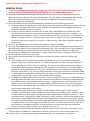
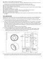
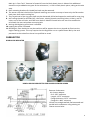
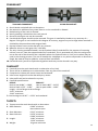
INDEX
Camshaft
Carburettor
13
4
Connecting Rod
12
Crankcase Cover
11
Crankshaft
13
Cylinder Head, Head Gasket, Valve Springs
Engine Block Internal
6
14
Engine Block
8
Engine Cooling Shrouds
5
Flywheel, Fan & Ignition System
10
Gear Box & Ring Gear
11
General Rules
2
Head
7
Intake and Exhaust Ports
8
Piston, Wrist Pin & Piston Rings
Rocker Arms – Push Rods – Studs
Tappets
11
7
13
Tech Procedure
3
Valves
7
1
UNLESS IT SAYS YOU CAN DO IT YOU CANNOT DO IT!!!
GENERAL RULES
1. “ANY GX UT2 ENGINES STARTING WITH GCBMT OR GCBPT WILL NOT BE LEGAL FOR JQMA’S 2012
SEASON. FURTHER EVALUATION IS REQUIRED BEFORE THESE ENGINES ARE ALLOWED.”
2. Only stock Honda GX120 HX 2 Engine and gearbox will be used in this class. All parts will be stock
Honda specifically made for the Honda GX120 K1HX2, U.S.GC01 GCAHK, and Canada GCAAT. Honda
OEM 120 replacement blocks may be used. Must be an OEM Honda replacement block. No
aftermarket blocks or components.
3. All stock Honda parts must be used and properly installed with the following exceptions:
a. Governor system may be partially or fully removed with the exception of the steel drive gear on the
crankshaft. This gear must remain intact. If shaft is removed hole must be plugged. Hole can be
tapped for thread or epoxy. No welding.
b. Factory air cleaner must be removed. Any air filter may be attached to the outside of air filter
adapter. Outer wear style or equivalent can be used over carburettor only with no adapter. The
approved air filter adapter may be run with or without an air filter. Any air filter may be used with
adapter as long as there are no devices inside the air filter or adapter. (I.E. Springs not allowed)
Hose from valve cover must go into a catch can. (We are using “outerwear” to define a style not
brand name).
4. Air filters are allowed, but must utilise air filter adapter number: 21034015
5. Any type of throttle linkage may be utilized. Carburettor shall remain unaltered with the exception of
the black plastic piece on the upper end of the throttle shaft. This is the ONLY part of the carburettor
that may be altered, removed of material from the black plastic piece is allowed. No additional
material may be added to the carburettor. i.e. bolt in black plastic piece or tubing on throttle stop.
6. Stock Honda fuel tank must be removed.
7. Recoil starter must be removed. Pull cup may be cut down for washer. Must use original cup.
8. Exhaust:
a. Stock Honda muffler will be removed. Mounting flange may be cut off of muffler and used as
adapter flange. Any transition from the “D” shape of the exhaust port to round must take place
with in the thickness (0.250” max). of the flange. This applies to all exhaust systems. No steps or
tapers allowed, grid marks are allowed past .25” flange area. No suspension for exhaust flange or
pipe infraction just disqualification. If an after market flange is used, maximum allowable flange
thickness will be 0.250”. If slip on type flange assembly is used, pipe stub will be a maximum 0.880
“ outside diameter tubing with a maximum overall length of 1.500”. Pipe stub must be inserted into
exhaust pipe at least 0.750” and will have minimal exhaust leakage.
b. All JQMA .25 midget mufflers to be used will be 4 to 8 hp Briggs & Stratton, part number 294599 or
equal equivalent. Muffler will be internally unaltered except that the round cup shaped baffle may
be welded to the perforated baffle without moving it’s original location. No drilling holes in the
baffles. Inside seam of baffle must be straight edged. (NOTE: Some seams may not be straight).
Threads will not be removed from the muffler. It is ok to weld a washer or nut on the flange for a
place to apply safety wire and/or spring.
c. Exhaust pipe will be a maximum of 1.000” outside diameter with a length of 20.0” to 26.0”
including a threaded pipe coupler welded to the end of the pipe in order to screw muffler in place
so that muffler may be removed for inspection. Pipe coupler will be a standard, unaltered, .” NP,
threaded coupler. Length will be 1.000” minimum to 2.250” maximum. Exhaust pipe length will be
measured by using a small diameter hose inserted though pipe to measure overall length. Flange
and coupler will be included in the overall length when measuring pipe. No coating of any type may
be applied to the interior of any part of the exhaust system. The intent of this rule is to have all of
the exhaust pass through the muffler. All measurements are to be taken with the component
pieces in the same position as they were installed and on the car.
9. Choke butterfly and shaft must be removed. Only the top hole may be filled only with silicone or old
shaft cut down. No addition or subtraction of material in the bore or venturi of the carburettor.
10. Oil level switch may be disconnected but switch assembly must remain intact in crankcase.
2
11. Gearbox may be rotated to any desired position.
12. Main Jet in carburettor will be “NON Tech”. Must be a OEM Honda Jet (brass or silver jet). Jet can be
drilled to any size. No modifications to the jet except for drilling the main hole.
13. On‐Off ignition switch may be removed, and hole covered. (any material: no welding)
14. All pin measuring gauges are plus tolerance.
15. Exhaust oxygen sensor or temperature sensor attached to any part of Honda exhaust system is illegal.
16. Valve seals are illegal.
17. Cryogenics of any Honda part is illegal.
18. Taking parts out of service ‐ Reference: Wear limits in Engine Block Internal section.
19. DQ only – Not suspension for: Exhaust, Air Filter Adapter, Spark Plug
20. Shroud may be factory RED or BLACK.
21. Honda gaskets for the intake, carb, side cover that are green on one side and tan on the other in colour
are legal.
TECH PROCEDURE
Modifications or machining of any parts except the gasket surfaces between the cylinder head and block,
and main jet in order to bring them to stated minimum or maximum specs (blueprinting) is not legal.
1. External visual check of engine for required components: Pipe and muffler, shrouds and sheet metal,
and oil level sensor (this can be partially observed from outside).
2. Factory air cleaner must be removed. Any air filter may be attached to the outside of air filter adapter.
Outerwear style or equivalent can be used over carburettor only with no adapter. The approved air
filter adapter may be run with or without an air filter. Any air filter may be used with adapter as long as
there are no device(s) used inside the air filter or adapter. (I.E. Springs not allowed) hose from valve
cover must go into a catch can.
(We are using “outerwear” to define a style not brand name).
3. Air filters are allowed, but must utilise air filter adapter number: 21034015
1. Air cleaner adapter will be maximum ID 2.250”and a maximum of 1.375” long in length, flange
thickness 0.375” max. flange ID 1.000” minimum hole size straight walled, flat bottomed and
parallel with carburettor using existing air cleaner mount holes.
4. Any Type throttle linkage may be utilized. Carburettor will be unaltered with the exception of the black
plastic piece on upper end of throttle shaft, this is the only part in the carburettor that can be altered,
3
Main jet is “Non Tech”. Removal of material from the black plastic piece is allowed. No additional
material may be added to any part of the carburettor, i.e. bolt in black plastic piece, tubing on throttle
stop.
5. Rear mounting brackets for Honda fuel tank may be removed.
6. The starter cup that is behind the flywheel retaining nut can be cut away to leave only the flat washer
back piece that retains cooling fan.
7. They keyed end of the ring gear shaft may be shortened, drilled and tapped or machined for snap ring.
8. Heli‐coiling threads for shrouds (all), valve cover, existing throttle mounting holes, oil drain, and fill
holes, one of the coil bolts, and side cover bolts is allowed. Dowel holes are not to be modified or
relocated, also one carburettor mounting bolt.
9. Honing and deglazing of the bore is allowed.
10. Lapping the valves is allowed.
11. Blocking air flow: No device may be used that will/or appear that it may impede air flow into the
engine cooling system. This may require that the engine be run at a speed above idle by the tech
personnel at the scale after the car has qualified or raced.
CARBURETOR
HONDA 120 INSULATOR
HONDA GX120 CARBURETOR FOR JUNIOR & SENIOR HONDA
Remove Carburettor:
Air cleaner adapter:
ID: 2.250” maximum
Length: 1.375” maximum
Flange thickness: 0.375” maximum
Flange ID: 1.000” minimum
ID hole size straight walled, flat bottomed and
parallel with carburettor using existing air
cleaner mount holes.
4
1. Check for restrictor, if applicable, and placement. Restrictor must be installed between carburettor and
carburettor insulator with stock Honda gasket on each side of restrictor. Only stock Honda insulator
gasket between black plastic insulator and head is permitted. Air passageway in insulator will not be
altered in any way. All Junior Honda’s must use the blue JQMA approved slotted plate only. Failure to
use proper restrictor plate, alteration of restrictor plate, or improper installation of plate in designated
class is cause for immediate DQ and all applicable suspensions will be applied.
2. Gasket thickness: 0.025” maximum.
3. Restrictor thickness: 0.0625” maximum. No slotting of holes on any Honda restrictor.
4. Insulator gasket thickness: 0.025” maximum
5. Check for any alterations or worn parts that would allow additional air into engine:
holes, slots, perforations, spacers, loose bolts, warped flanges, etc.
6. Two stock Honda intake gaskets may be used between Carburettor and plastic insulator.
7. Carburettor identification number:
a. Jr. Honda and Sr. Honda: BE 60 B and Thailand BE60 R
b. Heavy Honda: BE 65 B or Thailand 65Q
8. Check carburettor for alterations. Upper choke shaft hole may be sealed with silicone type sealer.
9. Honda 120 carb for Jr. and Sr. Honda
a. BE 60 B and Thailand BE60 R
b. Carburettor Bore: Intake end: Maximum diameter 0.950”
c. Throttle end: Maximum diameter 0.632”.
d. Carburettor venture bore 0.456” no go. This measurement is best made with a no go gauge but
may be made using a telescoping gauge as a no go.
e. Main jet in carburettor will be “Non Tech”. Must be a Honda OEM jet. (Brass or Silver Jet) Jet may
be drilled to any size. No other modifications.
f. Main air jet: 0.0394” maximum #60 (0.040”) no go – at back of hole
g. Main jet access passage: 0.094” maximum #41 (0.096”) no go
h. Main nozzle bore 0.069” maximum #50 (0.070”) nogo.
i. Main nozzle will be checked with a NOGO gauge (.429”) If gauge goes over dump tube‐carb is
illegal. This is best measured using a 0.452” rod type gauge with a 0.429” flat area to be used as a
go gauge.
j. Air vent holes on the side of the main nozzle must not be plugged.
k. Main nozzle must not be fastened into the carburettor body by anything other than the main jet. It
must not be epoxied or positioned by any other means.
l. Pilot jet: 0.0138” maximum #79 (0.0145”) no go
m. Pilot air jet: 0.050” minimum 1.25mm (0.0492”) go.
n. Pilot screw: no spec
o. Pilot seat diameter: 0.035” maximum #63 (0.038”) no go
p. Tip of pilot screw: 0.019” minimum.
q. Float bowl vent: 0.118” maximum #31 (0.120”) no go.
r. Needle valve seat: 0.065” maximum #51 (0.067”) no go.
s. The butterfly screw, the butterfly, and the throttle shaft must not be removed from the
carburettor. Any evidence of tampering will be a disqualification and suspension.
ENGINE COOLING SHROUDS
1. All pieces of the stock engine cooling shroud must be properly installed.
2. There must be no addition or subtraction of any material from the shrouding except for the covering of
the switch hole (any material). Starter cup may be altered to be used as washer retainer for the cooling
fan.
3. Remove engine cooling shrouds. Remove valve cover.
4. Zero dial indicator after exhaust bump. (0.050) ref.
5. Maximum valve lift will be checked from the top of valve spring retainer. Valves may be adjusted to
zero clearance or shims may be installed to create zero clearance. This may dictate making special
5
shims, as it is difficult to insert feeler gauge blades so as not to interfere with indicator contacts on
retainer.
Valve lift: Intake: 0.245” maximum
Exhaust: 0.255” maximum
CYLINDER HEAD, HEAD GASKET, VALVES, SPRINGS.
1. Remove cylinder head.
2. Head gasket thickness: 0.040” minimum thickness of inner rim.
3. Thickness of the head will be measured from valve cover surface to head gasket surface on the side, at
a position in line with the upper intake and exhaust flange bold. No angle milling of surface. Minimum
2.911.
MINIMUM 2.911
4. Remove valves.
5. Inspect retainers for alteration that would increase valve spring pressure. Both intake and exhaust
must have stock Honda retainers. Exhaust valve only can have lash cap and corresponding retainer.
6. Thickness of retainer will be:
Intake: 0.228” minimum
Exhaust 0.241” minimum
7. Flange thickness of retainer will be:
Intake: 0.110” maximum
Exhaust: 0.070” minimum
8. From flat of flange to machined surface:
Intake: 0.148” minimum
Exhaust: 0.165” minimum
9. All valve oil seals must be removed.
10. The use of valve seals is illegal and will result in applicable suspension per Honda suspension program.
VALVE SPRINGS
1. Valve springs will be stock Honda springs and will not be altered in any way. Use of
Honda GX120 or 140 valve springs legal
2. 120 springs
a. Wire diameter: 0.071” maximum
b. Outside diameter of spring: 0.790” maximum
c. Number of total coils: 5.3
d. Spring pressure: 11 lbs maximum at 0.812”
e. Stacked length will be: 0.394” maximum
6
3. 140 Springs
a. Wire Diameter: 0.079” maximum
b. Outside diameter of springs 0.808” maximum
c. Total number of coils: 7
d. Spring pressure: 16 lbs. maximum at 0.812”
e. Stacked length 0.524” maximum
ROCKER ARMS – PUSH RODS‐ STUDS
1. Rocker arms will be stock Honda and will not be altered in any way.
2. Rocker arm studs will be stock Honda. They or their mounting position may not be altered in any
manner. No heli‐coiling of mounting holes. No bending of studs.
3. Push rods will be stock Honda and will not be altered in any way.
Push rod length:
4.799” – 4.770”
VALVES
INTAKE VALVE
EXHAUST VALVE
1. Check valves for dimensions and weight.
2. Valve seating surface must be factory ground to a single angle only, 45 degrees. There will be no other
angles ground on any part of valve. Valves must not be polished, lightened or altered in any way.
3. Valve weight:
Intake 18 grams minimum
Exhaust 16 grams minimum
4. Drawing of valve dimensions (intake valve followed by exhaust valve)
HEAD
1. Cylinder head will be in “as cast” and in factory machined condition. There may be no addition or
subtraction of metal except for cylinder head gasket surface.
2. No use of any substance to the inside of the cylinder head. This includes no type of machining or
grinding to increase airflow. No angle milling, etc. or any alteration that could increase valve spring
pressure.
3. Thailand manufactured cylinder heads TKI‐4, ATA‐1 are not legal.
You may use older Japan Cylinder heads or the new # 13 Cylinder head.
4. Thickness of the head will be measured from valve cover surface to head gasket surface on the side, at
a position in line with the upper intake and exhaust flange bolt. No angle milling of surface. Minimum
2.911.
5. Cleaning of the combustion chamber or changing the finish of such chamber is illegal.
7
INTAKE AND EXHAUST PORTS
1. Ports will be in “as cast” and factory machined condition and there must be no addition or subtraction
of metal or any other substance to the inside or outside of the cylinder head.
2. No alterations of any kind to be made to the intake or exhaust port.
a. This includes any grinding, polishing, etching, sand blasting or glass beading to interior surface.
3. Valve seats must be a stock single 45 degree angle. Multi angle valve seats are not permitted. Valve
seats must not be replaced.
4. Intake and Exhaust ports at valve:
Intake:
Maximum 0.752”
Minimum 0.745”
Exhaust:
Maximum 0.675”
Minimum 0.665”
ENGINE BLOCK
Must be an OEM Honda Cylinder block. No aftermarket blocks.
1. This engine block must be in “as cast” and factory machined condition. There must be no addition or
subtraction of metal or any other substance to the inside or outside of the cylinder block, crankcase
cover, crankshaft, rod, piston, pin, rings, flywheel or coil with the following exceptions:
a. Removal of rear gas tanks brackets is permitted.
b. Removal of governor. Governor system may be partially removed with the exception of the steel
gear on the crankshaft. This gear must remain intact. Governor arm and shaft may be removed, tied
forward or altered to accommodate throttle linkage or return springs.
2. Addition of brackets, fittings etc. to accommodate throttle linkage, tachometer and temperature gauge
is allowed.
3. Cylinder head gasket surface may be milled, but must be flat. No angle milling allowed.
4. Check bore: 2.366” maximum.
NOTE: All measurements taken at top of bore or very bottom of bore, preferred method of
measurement is dial bore gauge, dial callipers may be used.
“Wear Limits/Parts Out of Service” JQMA reserves the right to confiscate 120 Honda engine parts
deemed illegal or at JQMA maximum wear limits. EXAMPLE: cylinder bore will be 2.366 maximum all
measurements taken at top of bore or very bottom of bore parallel to crank, 90 degrees from crank.
Any cylinder block that has one measurement over JQMA maximum wear limits will be taken out of
service. If no measurements exceed JQMA maximum wear limits the part of the block will not be
8
confiscated. Handler has the right to have confiscated parts returned to them but will be rendered
unusable.
5. Check stroke:
1.659” Maximum
1.640” Minimum
6. Measure amount that piston is up or down from block surface at T.D.C. This will be measured at the
edge of piston top and bottom and side to side. When measuring top and bottom of piston take an
average of the numbers measured i.e. top = .003, bottom = ‐.003 the piston to deck would be .000.
Measurement must NOT be taken in the centre or relieved part of the piston. This dimension will be:
0.000” Max – NO PISTON POP UP!!! Carbon may be removed to check pop‐up.
7. Install degree wheel on flywheel. Install pointer in order to read degrees. Locate accurate T.D.C. this
should be done with a positive stop type fixture and not established with indicator alone.
8. Cam will be checked with indicator reading off the top end of tappets which will provide zero
clearance. The inverted radius of the top of the tappet presents some problem to get accurate readings
and to prevent binding of indicator stem. Indicator holder and positions are very critical in this
operation.
9. Zero indicator on base circle of cam. Be sure that compression does not affect zeroing exhaust
indicator. (zero dial indicator after exhaust bump) ref.
10.Turning engine in normal rotation, clockwise facing flywheel, take reading at specified opening.
Readings must fall between specified degrees on the following chart.
CAMSHAFT PROFILE LIMITS
IN TAKE
Degrees
0.050” 10.5 to 14 ATDC
0.100” 26.5 to 30 ATDC
0.150” 45 to 48.5 ATDC
0.180 Split
0.200” 71 to 74.5 ATDC
Max lift .227 Peak 104 – 107 ATDC
0.200” 136 to 141 ATDC
0.180 split
0.150” 162.5 to 167 ATDC
0.100” 180.5 to 185 ATDC
0.050” 197.5 to 201 ATDC
EXHAUST
Degrees
0.050” 207 to 210.5 BTDC
0.100” 190 to 193.5 BTDC
0.150” 170.5 to 174.5 BTDC
0.180 Split
0.200” 144 to 148 BTDC
Max lift .229” Peak 107.5 ‐110.5” BTDC
0.200” 70.5 to 73.5 BTDC
0.180 split
0.150” 44.5 to 47.5 BTDC
0.100” 26 to 29.5 BTDC
0.050” 9 to 12.5 BTDC
11. Check max lift at intake and exhaust.
9
FLYWHEEL, FAN AND IGNITION SYSTEM
Tier III Flywheel
Tier II Flywheel
Magnet must be straight up Timing Key.
Caution should be used when removing flywheel. Do not hit with hammer or other heavy objects.
Service manual show flywheel to be removed with commercially available 6”puller. Another method is
inertia type knocker that threads onto crankshaft end.
1. The transistorized magneto ignition is fixed at 25 degrees BTDC and may not be altered in anyway.
2. Flywheel keyway or its position must not be altered.
3. deleted
4. Magnet and/or its position may not be altered in any way. Tier III magnet black, old style magnet
white.
5. Magnet retaining screw may not be altered in any way. Screw may not be replaced with larger or
smaller screw. No heli‐coiling of mounting hole.
6. Ignition coil and/or its position, other than air gap, may not be altered in any way.
a. Coil mounting bolts must be stock and cannot be altered in any way to advance or retard timing.
Coil attaching bolts will be stock 6mm cap screw 1‐1/16”long.
b. There can be no more than 3/8” of unthreaded portion of bolt that does not measure 0.230”
diameter. This restricts movement of coil to a position that could make ignition timing illegal.
c. If a coil support mount becomes stripped, it is permissible to heli‐coil. However, only one leg may
be repaired, if both legs are heli‐coiled, the block becomes illegal.
7. All nylon blades on the cooling fan.
8. No metal removal or addition to flywheel is permitted.
9. Flywheel weight will be: 1550 grams minimum
10. Flywheel diameter – magnet area: 6.285” minimum
11. A stock Honda spark plug cap, (wire end at resistor), must be used.
12. Any automotive type spark plug with 3/4” reach maximum is allowed.
13. No plug indexing washers allowed.
14. If temperature sensor is used under spark plug, factory washer may be removed.
GX‐120 FAN
10
GEAR BOX AND RING GEAR
1. Gear box may not be altered in any way.
a. May be rotated to desired position.
2. Ring gear may not be altered in any way with the exception of the keyed end of shaft that may be
shortened, drilled and tapped or machined for snap ring grove. No other machining, drilling, grinding
etc. to ring gear.
a. Key way may be cut deeper.
3. Ring gear may not be altered in any way including polishing or use of any compound or abrasive on
gear shaft where bearing rides.
4. Two gaskets maximum between gear box halves.
CRANKCASE COVER
1. Remove crankcase cover.
2. Cover must be in “as cast” and factory machined condition and there must be no addition or
subtraction of metal or any other substance to crankcase cover.
3. Crankcase cover gasket must be stock Honda. Only one gasket may be installed with a maximum
thickness of 0.025”.
4. Critical dimensions are thrust face of camshaft holder and position of crank bearing.
a. Place a straight edge over crank bearing and cam boss thrust face. These surfaces should be level.
b. Maximum tolerance will be 0.005”. There will be no alterations to crankcase cover. This includes any
alteration to crank bearing and camshaft holder position and height in an attempt to alter valve timing.
PISTON, WRIST PIN, AND PISTON RINGS
1. Remove rod and piston – triangle or boss on top of piston must point toward push rods
2. Piston, wrist pin and rings must be absolutely stock and not altered in any manner.
TIER III PISTON
TIER II PISTON
PISTON
1. Piston will be stock Honda standard size and will not be altered in any way.
2. Oversized pistons must not be used.
11
3. All three piston rings must be used
a. Top ring: Chrome compression ring installed with “N” or “T” on a rail up. No expander under ring.
b. Middle ring: Oil scraper ring installed with “N” or “T” on rail up. No expander under ring.
c. Bottom ring: Three (3) piece oil rings are allowed.
4. Piston may not be knurled, grooved or coated.
5. Piston weight:
106 grams minimum.
6. Total Piston weight with rings, pin, and clips:
121 grams minimum.
7. Total Piston weight with rings, pin, clips, complete with rod and bolts:
263 grams minimum.
8. See drawing for dimensions.
RINGS
1. Must be stock Honda rings with stock size and configuration.
2. No decreasing of ring tension by heating, machining or any other means.
3. Tier II Piston Ring Thickness:
a. Compression: 0.056” min.
b. Scraper: 0.056” min.
c. Oil ring: 3 piece lower 0.095” min.
i. 1 piece 0.097” min.
4. TIER III Ring Thickness:
a. Compression: 0.036” min.
b. Scraper: 0.036” min.
JQMA .25 GX120 Tech Manual 20
c. Oil Ring: 3 piece lower 0.095” min.
i. 1 piece 0.097” min.
5. The letter “N” or “T” on Tier III piston rings may not be legible after engine has been run.
WRIST PIN
1. Stock Honda wrist pin and retainer
a. OD: 0.511 ref.
b. Length: Minimum 1.844”
Maximum 1.864”
c. ID: 0.354” ref.
d. Weight: 23 grams minimum
CONNECTING ROD
1. Stock Honda rod with no alterations.
2. Connecting rod big end size:
1.021” minimum
1.0265” maximum
3. Pin end bore is 0.5111 ref.
4. Length from bottom of pin bore to top of big end bore will
be:
2.111” maximum
2.101” minimum
5. Rod weight with bolts: 119 grams or 4.2 oz minimum
6. No oil grooves on bearing surface of either end.
12
CRANKSHAFT
THAILAND CRANKSHAFT
JAPAN CRANKSHAFT
1.
2.
3.
4.
5.
6.
Stock Honda crankshaft with no alterations.
No removal or addition of any metal from or to the crankshaft is allowed.
No balancing of the crank is allowed
No oil grooving is allowed on the crank journal
Governor drive gear can not be removed.
Crankshaft drive gear should not be removed. This gear is installed by Honda to any accuracy of + .
degree. If this gear is not installed to this degree of accuracy; engine may not be legal when camshaft is
checked by the procedure under engine block.
7. Keyway location must not be altered in any manner.
8. Measure thrust to crank gear side: 3.345 Min.
9. The only cleaning method allowed is on the flywheel side of crankshaft for the purpose of removing
calcium, rust etc. from the exposed end of the crankshaft. This is permitted only from the seal groove
out to the end of the thread of the crankshaft where the flywheel bolts on. Only a wire wheel may be
used in the cleaning process. The use of Scotchbrite, sandpaper or any other compounds or abrasives is
illegal. No material may be added or removed from crankshaft.
10. Crankshaft main journal at flywheel and gearbox ends may not be altered in any way.
CAMSHAFT
1.
2.
3.
4.
5.
6.
Camshaft must be stock Honda with no alteration of any kind.
There will be no additions to or subtractions from any part of the camshaft.
Compression release will remain intact and unaltered.
Lobe centre angle will not be altered by any means.
Lobe profile will not be altered in any way.
Camshaft specifications
INTAKE
EXHAUST
Heel to heel 0.864” – 0.869”
Heel to heel 0.865” – 0.870”
Heel to Peak 1.079” – 1.093”
Heel to peak 1.081 – 1.095”
Length – thrust flange to thrust flange:
3.137” minimum
3.142” maximum
7. Cam bearings are 0.547” – 0.551” and unaltered.
TAPPETS
1. Tappets must be stock Honda with no alterations.
2. Base diameter:
0.909” minimum
No maximum spec.
3. Stem diameter:
0.312” minimum
4. Base thickness:
0.076” minimum
0.090” maximum
5. Length:
1.181” minimum
1.220” maximum
6. Weight:
16 grams minimum
13
ENGINE BLOCK INTERNAL
1. The engine block must be in an “as cast” and factory machined condition and there must be no
addition or subtraction of metal or any other substance to the inside or outside of the block except for
cylinder head gasket surface may be milled to achieve a 0.00 piston pop up. No angle milling of the
cylinder surface. Must remain flat.
2. Cylinder bore will be 2.366” maximum. NOTE: all measurements taken at top of bore or very bottom of
bore.
“Wear Limits/Parts Out of Service” JQMA reserves the right to confiscate 120 Honda engine parts
deemed illegal or at JQMA maximum wear limits. EXAMPLE: Cylinder bore will be 2.366 Max. all
measurements taken at top of bore or very bottom of bore parallel to crank, 90 degrees from crank.
Any cylinder block that has one measurement over JQMA maximum wear limits will be taken out of
service. If no measurements exceed JQMA maximum wear limits the part of block will not be
confiscated. Handler has the right to have confiscated parts returned to them but will be rendered
unusable.
3. Cylinder bore will not be bored oversize.
4. Cylinder bore will not be re‐sleeved.
5. Cylinder bore position will not be moved or tipped in any manner.
6. There will be no polishing, sandblasting or glass beading to any interior surface.
7. Machined surface of block down to thrust face of cam boss:
3.228” minimum
3.240” maximum
8. Machined surface of block down to bearing face:
3.430” minimum
3.442” maximum
9. Oil level sensor will be intact and unaltered. Wires may be externally disconnected or cut off.
Tech officials have the right to tech any or all cars in any class
at their discretion.
PLEASE NOTE: HONDA UT2 ENGINES ARE NOT
PERMITTED IN JQMA COMPETITION.
If it is not in any of the above rules, it is not
allowed.
14