1
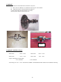
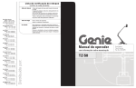
HONDA
TECH
MANUAL
GX160
HONDA ENGINE RULES
GENERAL RACING RULES SPECIFICALLY FOR
160 HONDA CLASS ONLY
Rusty Barnard , QMA Technical Director
First Issued: November 19, 1999
Updated March 17, 2011
1
HONDA CLAIM RULE - For GX160 QMA Type Engines
1.
All engine claims must follow procedure listed in QMA rulebook. Please see Article 6, Section 1
HONDA SUSPENSIONS
1.
All suspensions must follow procedure listed in QMA rulebook. Please see Article 6, Section 2
NOTE:
All shipping is to Express Mail at the shipper’s Expense
4 For the purposes of this rule only, if a handler has multiple cars competing in the Honda class (GX120 or GX160) at one race
event and more than one engine is found to be illegal at that event, it will be considered to be one offense.
5 Refusal of tech shall be interpreted as an admission that the engine is illegal and a suspension from the Honda class will be
immediate with all awards, qualifications being revoked.
6 Confiscation of part or parts - only the illegal part and all related parts and not the whole motor will be confiscated. A full motor
tear down is required if an illegal part is found.
7 Novice Honda:
The novice program and its implementation fall under the Regional Directors. Therefore illegal Honda engine parts will be
confiscated but the suspension will not be levied against handlers or drivers for the first offense only.
2
GENERAL RULES
1.
Only stock Honda GX160K1 HX2 and HX26* engine and gearbox will be used in this class. All parts will be stock
Honda specifically made for the Honda GX160OK1 HX2. U.S. # GCACK & GCAAK – Canada #GCABT
A. All 160 Honda engines must be updated to the new E2 Style piston and cylinder head.
B. Failure to update = DQ and Minimum 6 month suspension
All stock Honda parts must be used and properly installed with the following exceptions:
The following gaskets (list below) that are coming from Honda are tan and green will be legal to use.
Intake Gasket, Carb Gasket, Side Cover Gasket
A. Governor system may be partially or fully removed with the exception of the steel drive gear on the
crankshaft. This gear must remain intact. If shaft is removed, hole must be plugged. Hole can be taped for thread
or epoxy. No welding.
B. Factory air cleaner must be removed. Any air filter may be attached to the outside of air filter adapter.
Outer wear style or equivalent can be used over carburetor only with no adapter. The approved air filter
adapter may be run with or without an air filter. Any air filter may be used with adapter as long as there are
no devices inside the air filter or adapter. (I.E. Springs not allowed) Hose from valve cover must go into a
catch can. (We are using “outerwear” to define a style not brand name).
1. The use of air filters during qualifying at asphalt and dirt events is illegal. The Senior Tech Official
reserves the right to allow filters at any event that it’s deemed necessary.
C. Stock Honda fuel tank must be removed.
D. Recoil starter must be removed. Pull cup may be cut down for washer. Must use original cup.
E. Exhaust: Stock Honda muffler will be removed. Mounting flange may be cut off of muffler and used as
adapter flange. Any transition from the “D” shape of the exhaust port to round must take place with in the
thickness (0.250” max.) of the flange. This applies to all exhaust systems. No steps or tapers allowed, grind
marks are allowed past .25” flange area. No suspension for exhaust flange or pipe infraction just
disqualification. If an after market flange is used, maximum allowable flange thickness will be 0.250
inches. If slip on type flange assembly is used, pipe stub will be a maximum 0.880 inches outside diameter
tubing with a maximum overall length of 1.500” inches. Pipe stub must be inserted into exhaust pipe at
least 0.750 inches and will have minimal exhaust leakage. Muffler to be used will be 4 to 8 hp Briggs &
Stratton, part number 294599 or equal equivalent. Muffler will be internally unaltered except that the round
cup shaped baffle may be welded to the perforated baffle without moving it’s original location. Threads
will not be removed from muffler. Exhaust pipe will be a maximum of 1.000” inches outside diameter with
a length of 20.0” to 26.0” including a threaded pipe coupler to welded to the end of the pipe in order to
screw muffler in place so that muffler may be removed for inspection. Pipe coupler will be a standard,
unaltered, ¾” NP, threaded coupler. Length will be 1.000” inches minimum to 2.250” inches maximum.
There will be no steps or tapers in exhaust pipe or flange assembly. Exhaust pipe length will be measured
by using a small diameter hose inserted though pipe to measure over all length. Flange and coupler will be
included in the overall length when measuring pipe. No coating of any type may be applied to the interior
of any part of the exhaust system. The intent of this rule is to have all of the exhaust pass through the
muffler. All measurements are to be taken with the component pieces in the same position as they were
installed and on the car.
1. All 160 ¼ midget mufflers must be Briggs & Stratton Part # 294599 or equivalent. No drilling
holes in the baffles. Inside seam of baffle must be straight edged. (NOTE: Some seams may not
be parallel in baffle) You cannot cut off the threaded flange if it is to be used in Honda. It is OK
to weld a washer or nut on the flange for a place to apply safety wire
F. Choke butterfly & shaft must be removed. Hole may be filled only with silicone. Old shaft may be cut down.
G. Oil level switch may be disconnected but switch assembly must remain intact in crankcase.
H. Gearbox may be rotated to any desired position.
3
I. Main jet in carburetor may be a maximum of #82 (0.033 nogo). Silver jets are legal.
J. Off-On ignition switch may be removed, and hole covered. (any material; no welding)
K. All pin measuring gauges are plus tolerance.
L. Exhaust oxygen sensor or temp. sensor attached to any part of Honda exhaust system is illegal.
M. Valve seals are illegal. (Event DQ only NO suspension.)
N. Cryogenics of any Honda part is illegal.
O. Note: Taking parts out of service reference to “Wear Limits” in Engine Block Internal section.
P. DQ Only – Not suspension for: Exhaust, Air Filter Adapter, Spark Plug or valve seal.
Q. Shroud must be factory RED or BLACK.
TECH PROCEDURE
Modifications or machining of any parts in order to bring them to stated minimum or maximum specs
(blueprinting) is not legal.
External visual check of engine for required components: muffler, shrouds and sheet metal, oil level sensor
(this can be partially observed from outside).
NOTES:
A.
Factory air cleaner must be removed. Any air filter may be attached to the outside of air filter
adapter. Outerwear style or equivalent can be used over carburetor only with no adapter. The
approved air filter adapter may be run with or without an air filter. Any air filter may be used with
adapter as long as there are no devices inside the air filter or adapter. (I.E. Springs not allowed)
Hose from valve cover must go into a catch can. (We are using “outerwear” to define a style not
brand name).
1 . The use of air filters during qualifying at asphalt and dirt events is illegal. The Senior
Tech. Official reserves the right to allow filters at any event that it’s deemed necessary.
Senior Tech. Official reserves the right to allow filters at any event that it’s deemed
necessary.
4
B.
b.
Any type throttle linkage may be utilized. Carburetor will be unaltered with the exception of the
black plastic piece on upper end of throttle shaft, this is the only part in the carburetor that can
be altered.
Material may not be added to throttle stop area of black plastic piece or carb body.
C.
D.
Rear mounting brackets for Honda fuel tank may be removed.
The starter cup that is behind the flywheel-retaining nut can be cut away to leave only the flat
washer back piece that retains cooling fan.
E. The keyed end of the ring gear shaft may be shortened, drilled and tapped or machined for snap ring
Heli-coiling threads for shrouds (all), valve cover, existing throttle mounting holes, oil
drain, and fill holes, one of the coil bolts, and side cover bolts is allowed. Dowel
holes are not to be modified or relocated, also one carburetor mounting bolt.
G. Honing and deglazing of the bore is allowed.
H. Lapping the valves is allowed.
I. Blocking Air Flow: No device may be used that will/or appear that it may impede
Air flow into the engine cooling system. This may require that the engine be run at a
speed above idle by the tech personnel at the scale after the car has qualified or raced
F.
CARBURETOR
Remove Carburetor:
A.
Check for any alterations or worn parts that would allow additional air into engine: holes, slots,
perforations, spacers, loose bolts, warped flanges etc
a.
b.
Gasket thickness: 0.025” maximum.
Insulator gasket thickness: 0.025” maximum
B. Carburetor identification number: BE 65 B Thailand BE 65 Q
C. Check carburetor for alterations. Upper choke shaft hole may be sealed with silicone type sealer.
D. Carburetor Bore: Intake end: maximum diameter 0.951” ref. Throttle end: maximum diameter 0.710.
E. Carburetor venturi bore: 0523- no/go. This measurement is best made with a no go gauge but may
be made using a telescoping gauge as a no go.
F. Main jet and main nozzle: (MUST BE TIGHT)
5
Air Jet
1.
2.
Main jet size: maximum #82 - 0.033 no/go.
Jet must be stock unaltered. As of 4-1-10 any jet pin goes in and sticks will be a DQ.
Main air jet: 0.0587” maximum #53 (0.0595”) no go - at back of hole.
Main jet access passage: 0.0942” maximum #41 (0.096”) no go.
Main nozzle:
Main nozzle bore 0.0732” maximum #47 (0.078”) no go.
Main nozzle will be checked with a No/Go Gauge ( 0.424”) If gauge goes over dump tube –
carb is illegal.. This is best measured using a 0.452” rod type gauge with a 0.424” flat area
to be used as a go gauge.
3. Air vent holes on the side of the main nozzle must not be plugged.
4. Main nozzle must not be fastened into the carburetor body by anything other than the main
jet. It must not be epoxied or positioned by any other means.
Slow speed system:
1. Pilot jet: 0.0135” maximum #79 (0.0145”) no go.
2. Pilot air jet: 0.0478” maximum #55 (0.052”) no go.
3. Pilot screw: no spec
4. Pilot seat diameter: 0.0365” maximum #61 (0.039”) no go.
5. Tip of pilot screw: 0.020” minimum.
H.
Float bowl vent : 0.118” maximum #31 (0.1200”) no go.
I.
Needle valve seat: 0.0685” maximum #50 (0.070”) no go.
J.
The butterfly screw, the butterfly, and the throttle shaft must not be removed from the carburetor.
Any evidence of tampering will be a disqualification and suspension.
K.
Decimal equivalents of numbered size drills chart on page 20.
6
ENGINE COOLING SHROUDS
A.
B.
All pieces of the stock engine-cooling shroud must be properly installed.
There must be no addition or subtraction of any material from the shrouding except for the
covering of the switch hole. (Any material). Starter cup may be altered to be used as washer
retainer for the cooling fan.
1. Remove engine-cooling shrouds. Remove valve cover.
2. Zero dial indicator after exhaust bump. (0.050) ref.
3. Maximum valve lift will be checked from the top of valve spring retainer. Valves may
be adjusted to zero clearance or shims may be installed to create zero clearance. This
may dictate making special shims, as it is difficult to insert feeler gauge blades so as not
to interfere with indicator contracts on retainer.
Valve lift:
Intake: 0.245 Maximum
Exhaust: 0.255 Maximum
7
CYLINDER HEAD, HEAD GASKET, VALVES, SPRINGS
Remove cylinder head.
Head gasket thickness:
0.040” minimum thickness of inner rim.
Measure from head surface to top of valve head:
Intake:
maximum 0.264”
Exhaust:
maximum 0.250”
Minimum 0.242”
Minimum 0.225”
This is best done with a depth micrometer or a bridge type dial indicator. Bridge type does not require
removing carbon from head surface. See photo on next page.
Combustion chamber cc:
17.2 cc. Ref. with stock spark plug
Remove valves:
A.
Retainer:
Inspect retainers for alteration that would increase valve spring pressure. Both intake and
exhaust must have stock Honda retainers. Exhaust valve only can have lash cap and
corresponding retainer.
B.
Thickness of retainer will be:
Intake: 0.228” minimum
Exhaust: 0.241” minimum
C.
Flange thickness of retainer will be:
Intake: 0.110” maximum
Exhaust: 0.070” maximum
D.
From flat of flange to machined surface:
Intake: 0.148” minimum
Exhaust: 0.165” minimum
All Valve oil seals must be removed 1. The use of valve seals is illegal and will result in event DQ only.
8
VALVE SPRINGS
Valve springs will be stock Honda springs and will not be altered in any way.
160 Spring
140 Spring
A.
B.
C.
D.
E.
Wire diameter: 0.071” Maximum
Outside diameter of spring: 0.790” Maximum
Number of total coils: 5.3
Spring pressure: 11 LBS max. at 0.812”
Stacked length will be: 0.394” Maximum
A. Wire diameter: 0.079” Maximum
B. Outside diameter of spring: 0.808” Maximum
C . Number of total coils: 7
D . Spring pressure: 16 LBS max. at 0.812”
E. Stacked length will be: 0.524” Maximum
ROCKER ARMS – PUSH RODS – STUDS
Rocker arms will be stock Honda and will not be altered in any way. Rocker arm studs will be stock
Honda. They or their mounting position may not be altered in any manner. No heli-coiling of mounting
holes. No bending of studs. Push rods will be stock Honda and will not be altered in any way. Push rod
length will be 5.257-5.279”.
VALVES
A. Check valves for dimensions and weight. Valve seating surface must be factory ground to a single
angle only, 45 degrees. There will be no other angles ground on any part of valve. Valves must
not be polished, lightened or altered in any way.
B.
Valve weight:
C.
Exhaust 22 grams minimum
Drawing of valve dimensions (Intake Valve followed by Exhaust Valve
Intake 22 grams minimum
9
HEAD
Cylinder head will be in “as cast” and in factory machined condition and there must be no addition or subtraction of
metal or any other substance to the inside or outside of the cylinder head. This include no type of machining or grinding
to increase compression or airflow. No milling, angle milling etc. or any alteration that could increase valve spring
pressure. Note: Do not use abrasive material in cleaning head and cylinder deck that will alter factory finish. For Thailand
produced cylinder heads casting numbers ATA-3, ATA-6, TK1-10, TKI-11 other numbers to follow. Short Radius must
be sharp edged. Minor imperfections may be present on corner between cast port and machined bowl area (short radius)
The intent of this description is to prohibit any attempt to alter the cylinder head ports as received from the manufacturer.
See cylinder head photos.
A. Measure from flat of head surface down to valve seat. This dimension will be:
maximum 0.305”
minimum 0.287”
B. Measure from surface of head to top of valve guide. This dimension will be: 1.010” Maximum
10
C.
Measure from surface of head to lowest machined area in the bowl of the port. This dimension will be:
Intake: 1.062 - 1.170” maximum
Exhaust: 1.103 - 1.122” maximum
D. Thickness of head. This will be measured from valve cover surface to head gasket surface at the side
at a position in line with upper intake & exhaust flange bolt.
Maximum 2.917”
Minimum 2.911” Thailand heads 2.904”
INTAKE AND EXHAUST PORTS
A. Ports will be “as cast” and in factory machined condition and there must be no addition or subtraction of
metal or any other substance to the inside or outside of the cylinder head.
B. No alterations of any kind to be made to the intake or exhaust port.
C. This includes any grinding, polishing, etching, sand blasting or glass beading to interior surface.
D. Valve seats must be a stock single 45 degree angle. Multi angle valve seats are not permitted. Value
seats must not be replaced.
E. Intake and Exhaust ports at valve:
Intake: maximum 0.915” minimum 0.900”
Exhaust: maximum 0.863” minimum 0.858”
ENGINE BLOCK
This engine block must be “as cast” and in factory machined condition. There must be no addition
or subtraction of metal or any other substance to the inside or outside of the cylinder block, crankcase
cover, crankshaft, rod, piston, pin, rings, flywheel or coil with the following exceptions:
A.
B.
C.
Removal of rear gas tanks brackets is permitted.
Removal of governor. Governor system may be partially removed with the exception of the steel gear on the crankshaft.
This gear must remain intact. Governor arm and shaft may be removed, tied forward or altered to accommodate throttle
linkage or return springs.
Addition of brackets, fittings etc. to accommodate throttle linkage, tachometer, temperature gauge is allowed.
Check bore:
2.681” maximum
11
NOTE: All measurements taken at top of bore or very bottom of bore.
“Wear Limits/Parts Out Of Service” QMA reserves the right to confiscate 160 Honda engine
parts deemed illegal or at QMA maximum wear limits. EXAMPLE: Cylinder Bore will be 2.681
Max. All measurements taken at top of bore or very bottom of bore parallel to crank, 90 degrees
from crank. Any cylinder block that has one measurement over QMA maximum wear limits will
be taken out of service. If no measurements exceed QMA maximum wear limits the part of block
will not be confiscated. Handler has the right to have confiscated parts returned to them but will
be rendered unusable
Check stroke:
1.778 maximum to 1.758” minimum
Measure amount that piston is up or down from block surface at T.D.C. This will be measured at edge or
highest part of piston, not in center or relieved area.
This dimension will be: 0.000” Maximum
NO PISTON POP UP
Install degree wheel on flywheel. Install pointer in order to read degrees. Locate accurate T.D.C. This
should be done with a positive stop type fixture and not established with indicator alone.
Cam will be checked with indicator reading off the top end of tappets, which will provide zero clearance.
The inverted radius of the top of the tappet presents some problem to get accurate readings and to prevent
binding of indicator stem. Indicator holder and positions are very critical in this operation
.
Zero indicator on base circle of cam. Be sure that compression release does not affect zeroing exhaust
indicator. Zero dial indicator after exhaust bump ( 0.050) ref.
Turning engine in normal rotation, clockwise facing flywheel, take reading at specified opening.
Readings must fall between specified degrees on the following chart.
12
CAMSHAFT PROFILE LIMITS
IN TAKE
EXHAUST
Degrees
Degrees
0.050”
10.5 to 14
ATDC
0.050”
207 to 210.5
BTDC
0.100”
26.5 to 30
ATDC
0.100”
190 to 193.5
BTDC
0.150”
45 to 48.5
ATDC
0.150
170.5 to 174.5
BTDC
0.180 Split”
0.200”
71 to 74.5
Maxlift .227”
0.200
0.180 Split”
ATDC
0.200”
Peak 104 – 107 ATDC
136 to 141
Maxlift .229”
ATDC
0.200
0.180 Split”
144 to 148
BTDC
Peak 107.5 - 110.5
BTDC
70.5 to 73.5
BTDC
0.180 Split”
0.150”
162.5 to 167
ATDC
0.150”
44.5 to 47.5
BTDC
0.100”
180.5 to 185
ATDC
0.100”
26 to 29.5
BTDC
0.050”
197.5 to 201
ATDC
0.050”
9 to 12.5
BTDC
Check max lift at intake and exhaust.
FLYWHEEL, FAN AND IGNITION SYSTEM
Caution should be used when removing flywheel. Do not hit with hammer or other heavy objects.
Service manual show flywheel to be removed with commercially available 6” puller. Another method is
inertia type knocker that threads onto crankshaft end.
The transistorized magneto ignition is fixed at 25 degrees BTDC and may not be altered in
any way. Firing must not exceed 0.104 “or 26 degrees BTDC.
Quick check: Turning flywheel clockwise-if the leading edge of the depression of flywheel rim
where the magnet is mounted is not still under the right hand coil leg at0.115” BTDC, it is probably
illegal and should be checked further. If timing needs to be checked further see page 19.
A. Flywheel keyway or its position must not be altered.
B. Key may not be deleted or altered in any way.
C. Magnet and its position may not be altered in any way.
D. Magnet retaining screw may not be altered in any way. Screw may not be replaced with larger
or smaller screw. No heli-coiling of mounting hole.
13
E.
Ignition coil or its position, other than air gap, may not be altered in any way. Coil mounting
bolts must be stock and cannot be altered in any way to advance or retard timing. Coil attaching
bolts will be stock 6mm cap screw l-1/16” long. There can be no more than 3/8” of unthreaded
portion of bolt that does not measure 0.230” diameter. This restricts movement of coil to a
position that could make ignition timing illegal. If a coil support mount becomes stripped, it is
permissible to heli-coil. However, only one leg may be repaired, if both legs are heli-coiled, the
crankcase becomes illegal.
F
. All nylon blades on the cooling fan must be intact.
G.
No metal may be added or removed from the flywheel.
Flywheel weight will be:
2360grams minimum
H.
A stock Honda spark plug cap, (wire end and resistor), must be used.
I.
Any automotive type spark plug with ¾”reach maximum is allowed. Tapered seat plugs are not allowed. Race
DQ only.
J.
No plug-indexing washers allowed.
K.
If temperature sensor is used under spark plug, factory washer must be removed.
14
GEAR BOX AND RING GEAR
A.
Gear box may not be altered in any way. May be rotated to desired position.
B.
Ring gear may not be altered in any way with the exception of the keyed end of shaft that may
be shortened, drilled and taped or machined for snap ring grove. No other machining, drilling,
grinding etc. to ring gear. Keyway may be cut deeper.
C.
Ring gear may not be altered in any way including polishing or use of any compound
or abrasive on gear shaft where bearings ride.
D.
Two gaskets maximum between gear box halves.
CRANKCASE COVER
Remove crankcase cover.
A.
Cover must be “as cast” and in factory machined condition and there must be no addition or subtraction of metal or
any other substance to crankcase cover.
B.
Crankcase cover gasket must be stock Honda. Only one gasket may be installed with a maximum thickness of
0.025”
Critical dimensions are - thrust face of camshaft holder and position of crank bearing. Place a straight edge
over crank bearing and cam boss thrust face. These surfaces should be level. Maximum tolerance will be +
0.005”. There will be no alterations to crankcase cover. This includes any alteration to crank bearing and
camshaft holder position and height in an attempt to alter valve timing.
15
PISTON – WRIST PIN AND PISTON RINGS
Remove rod and piston – triangle or dot on top of piston must point toward push rods - piston, wrist pin
and rings must be absolutely stock and not altered in any manner.
PISTON NOTES
Piston will be stock Honda standard size and will not be altered in any way.
A. Oversized pistons must not be used.
B. All three piston rings must be used and installed properly.
1. Top ring: Chrome compression ring installed with “N” Thailand rings marked R on rail up. No expander
Under ring
2. Middle ring: Oil scraper ring installed with “N” or R on rail up. No expander under
ring.
2. Bottom ring: Three (3) piece oil rings are allowed. Check oil ring expander for alterations that will alter
ring tension (cutting ends of expander ect.)
C. Piston may not be knurled, grooved or coated
D. Total Piston weight: With rings, pin, and clips 200 grams minimum
E.
Minimum total combined weight: 359 Grams = (Piston, rings, complete rod w/ bolts wrist pins
& retainers.)
F.
See drawing for dimensions
16
RINGS
A.
Must be stock Honda rings with stock size and configuration.
B.
No decreasing of ring tension by heating, machining or any other means.
C
Ring thickness:
Compression:
Scraper:
Oil Ring:
Tier III
0.056” min. Compression
0.036” min.
0.056” min. Scraper
0.036” min.
3 piece oil ring = 0.095 min. 1 piece oil ring = 0.097 min.
WRIST PIN
Stock Honda wrist pin and retainer
OD: Minimum
Length: Minimum
ID:
Weight:
0.708” Maximum 0.709”
2.120” Maximum 2.128”
0.556” ref. +/40 grams minimum
17
CONNECTING ROD
Stock Honda rod with no alterations.
A. Connecting rod big end size:
1.176 ” minimum -
B. Pin end bore is:
.710” ref.
1.184” maximum
C. Length from bottom of pin bore to top of big end bore will be:
2.3755” maximum
2.3580” minimum
D. Rod weight with bolts:
140 grams
E. No oil grooves on bearing surface of either end.
CRANKSHAFT
Stock Honda crankshaft with no alterations.
Notes:
A. No removal or addition of any metal from or to the crankshaft is allowed.
B. No balancing of the crank is allowed.
C. No oil grooving is allowed on the crank journal.
D. Governor drive gear cannot be removed.
E. Crankshaft drive gear should not be removed. This gear is installed by Honda to any accuracy of + ½
degree. If this gear is not installed to this degree of accuracy, engine may not be legal when camshaft is
checked by the procedure under engine block.
F. Keyway location must not be altered in any manner.
G. Measure thrust to crank gear side = 3.350 Min.
H. Factory heat treating markings must be present on gearbox end of crankshaft and must be evident on all
non –contact areas . The only cleaning method allowed is on the flywheel side of crankshaft for the
purpose of removing calcium, rust etc. from the exposed end of the crankshaft. This Is permitted only from
the seal groove out to the end of the thread of the crankshaft where the flywheel bolts on. Only a wire
wheel may be used in the cleaning process. The use of Scotchbrite, sandpaper or any other compounds or
abrasives is illegal. No material may be added or removed from crankshaft. Crankshaft main journal at
flywheel and gearbox ends may not be altered in any way. Thailand crankshafts have no heat treat marks.
NOTE: Refer to photo of crank color.
18
CAMSHAFT
Camshaft must be stock Honda with no alteration of any kind.
A. There will be no additions to or subtractions from any part of the camshaft.
B. Compression release will remain intact and unaltered.
C. Lobe center angle will not be altered by any means.
D. Lobe profile will not be altered in any way.
Thailand
CAMSHAFT SPECIFICATIONS
INTAKE EXHAUST
Heel to Heel
. 0.865” - 0.869”
Heel to Heel
0.866” - 0.870”
Heel to Peak
1.079” - 1.093”
Heel to Peak
1.081”- 1.095”
Length - thrust flange to thrust flange:
3.137” minimum
3.142” maximum
Cam bearings are 0.547” - 0.551” and unaltered( UNDER .547 MINIMUM TO BE TAKEN OUT OF SERVICE NO DQ)
19
TAPPETS
A. Tappets must be stock Honda with no alterations.
B. Base diameter:
0.910” minimum
no maximum spec
C. Stem diameter:
0.312” minimum
D. Base thickness:
0.073” minimum
E. Length:
F. Weight:
1.180” minimum
0.090” maximum
1.220” maximum
16 grams minimum
ENGINE BLOCK INTERNAL
The engine block must be in an “as cast” and factory machined condition and there must be no
addition or subtraction of metal or any other substance to the inside or outside of the block.
A. Cylinder bore will be
2.681” maximum.
1. “Wear Limits/Parts Out Of Service” QMA reserves the right to confiscate 160 Honda engine
parts deemed illegal or at QMA maximum wear limits. EXAMPLE: Cylinder Bore will be 2.681
Max. All measurements taken at top of bore or very bottom of bore parallel to crank, 90 degrees
from crank. Any cylinder block that has one measurement over QMA maximum wear limits will
be taken out of service. If no measurements exceed QMA maximum wear limits the part of block
will not be confiscated. Handler has the right to have confiscated parts returned to them but will be
rendered unusable. Handler has the right to have confiscated parts returned to them but will be
rendered unusable.
B. Cylinder bore will not be bored oversize.
C. Cylinder bore will not be re-sleeved.
D. Cylinder bore position will not be moved or tipped in any manner.
E. Cylinder block deck will not be resurfaced by any means. There will be no polishing, sandblasting
or glass beading to any interior surface.
F.
Deck height:
G.
Machined surface of block down to thrust face of cam boss:
3.220” minimum
3.235” maximum
5.123” minimum
H. Machined surface of block down to bearing face:
3.416” minimum
I.
5.127” maximum
3.435” maximum
Oil level sensor will be intact and unaltered. Wires may be externally disconnected or cut off.
20
PROCEDURE FOR CHECKING TIMING
A.
With degree wheel or indicator located at 0 degrees or TDC., mark both the flywheel and some fixed
point (such as right hand side of aluminum block casting right above flywheel) with aligning marks. Turn
the flywheel clockwise and stop at 26 degrees BTDC or 0.103”- 0.104” BTDC on your indicator. Make
another mark on the block casting that aligns with your mark on the flywheel.
B.
Remove dial indicator so it will not be damaged by engine rotation.
C.
Install timing light to a battery, if not self powered, and clamp inductive pickup to spark plug
wire. Wire should be hooked to standard spark plug gapped to 0.025”. Using a drill, with an
extension that is cut off or turned to fit drill, place socket on flywheel nut and rotate engine in clockwise
direction.
D. Fire the timing light and observe. If the reference mark on the flywheel is between the two
marks on block casting that are TDC and 0.104 “ or 26 degrees BTDC, the timing is legal. If mark is not
between marks on block casting when rotating, the engine will be disqualified.
Tech officials have the right to tech any or all cars in any class at their
discretion. Tech Officials follow the same chain of command as all
officers of QMA – as follows: Local – Regional – National I.E.
Regional tech officials can tech at any event at their region and
National Tech Officials can tech at any event in QMA. National Tech
Director is final authority on all tech issues.
21
DECIMAL EQUIVALENTS OF NUMBER SIZE DRILLS
No.
1
2
3
4
5
6
7
8
9
10
11
12
13
14
15
16
17
18
19
20
Size in
Decimals
.2280
.2210
.2130
.2090
.2055
.2040
.2010
.1990
.1960
.1935
.1910
.1890
.1850
.1820
.1800
.1770
1730
.1695
.1660
.1610
Size in
No. Decimals
No.
21
22
23
24
25
26
27
28
29
30
31
32
33
34
35
36
37
38
39
40
41
42
43
44
45
46
47
48
49
50
51
52
53
54
55
56
57
58
59
60
.1590
.1570
.1540
.1520
.1495
.1470
.1440
.1405
.1360
.1285
.1200
.1160
.1130
.1110
.1100
.1065
.1040
.1015
.0995
.0980
22
Size in
Decimals
.0960
.0935
.0890
.0860
.0820
.0810
.0785
.0760
.0730
.0700
.0670
.0635
.0595
.0550
.0520
.0465
.0430
.0420
.0410
.0400
Size in
No. Decimals
61
62
63
64
65
66
67
68
69
70
71
72
73
74
75
76
77
78
79
80
.0390
.0380
.0370
.0360
.0350
.0330
.0320
.0310
.0292
.0280
.0260
.0250
.0240
.0225
.0210
.0200
.0180
.0160
.0145
.0135