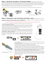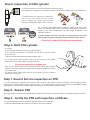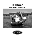
1
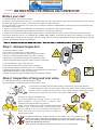
MAZU MARINE INFLATABLE PFD'S
E-mail:[email protected]
INSTRUCTIONS FOR ANNUAL SELF INSPECTION
Applicable for PFDs in recreational use only, for PFD's in commercial use inspections should only be performed by an accredited agent.
Before you start
1. Carefully read over all the instructions below
2. Ensure you have spare parts for your PFD. On inflator heads that use a green indicator clip to retain the manual firing lever, the clip will
be broken during inspection. Ensure you have spare clips before you begin inspection.
You may also need to replace the CO2 cylinder and on automatic models the cartridge/bobbin. All these parts can be purchased through
the retailer or manufacturer.
3. Ensure you have access to accurate kitchen or letter scales for checking the weight of the CO2 cylinder.
4. Print a copy of the Inflatable PFD self inspection certificate for every PFD being inspected
5. Record on the certificate the PFDs serial/PI number, model no., inflator head brand / type (manual or automatic) and last service date.
Record each inspection step as it is completed with a Pass, Fail or NA in check boxes provided on the certificate. If the PFD or a
component fails any inspection step 1 through 6, the PFD or faulty component must be replaced before using the PFD, alternatively send the
PFD to an accredited service agent for further test.
Step 1. General inspection
1.1 External Inspection - Check
a) Cover has no excessive wear or visible damage.
b) All cover closures (hook and loop, zippers etc) are serviceable.
c) There is no visible damage or wear to any straps or stitching.
d) All fastenings, adjustments and buckles are operating correctly.
e) Safety lanyard attachment ring (when fitted) is not worn or damaged.
1.2 Internal Inspection - Open cover and check
a) retro-reflective tape is firmly attached and not damaged.
b) Lifting becket webbing and stitching is not worn or damaged.
c) Whistle operation (blow to check operation) and that whistle is securely attached.
d) Oral inflation tube has no visible signs of damage.
e) If fitted with emergency light check lights expiry date (replace if expired).
Step 2. Inspection of lung and oral valve
2.1 Check lung has no signs of excessive abrasion or wear.
Pay extra attention to the folds and areas around inflation systems
2.2 a) Remove Co2 cylinder from the inflator head by unscrewing the cylinder anti-clockwise.
On models fitted with a UML Pro Sensor inflator head check that the manual indicator status (top
window) is red once cylinder has been removed. The Pro Sensor manual indicator status window
should only show green when an unpierced CO2 cylinder is fitted correctly.
12h
b) Inflate lung using the oral inflation tube.
c) Leave lung inflated with oral tube cap off in a room with a
stable temperature of around 20 oC for at least 12 hours
(temperature changes will affect lung pressure)
d) After 12 hours check there is no loss of pressure and no visible
damage to lung. If lung is damaged or pressure falls the PFD
must be replaced or sent to an accredited service station for
further tests. Under no circumstances should you attempt to
repair the PFD yourself
2.3 Deflate inflatable lung checking operation of oral inflation valve. Only deflate lung by
inverting the oral tube cap and gently pressing the top of the inverted cap down into tube.
Do not put anything other than the inverted cap into the oral inflation tube, foreign
objects may damage the oral valve.
When the lung is fully deflated fit the oral tube cap back into its normal position.
Step 3. Examine operation of manual inflator
(applicable for all inflator heads)
3.1 With CO2 cylinder removed pull manual firing lanyard down sharply to ensure lever moves freely and that the piercing cutter becomes
proud of the sealing washer at base of the upper threaded section. On inflator heads where the lever is secured by a green indicator clip
this action will break the indicator clip. If lever movers freely and piercing cutter becomes proud fold lever back up into normal position.
3.2 On inflator heads that use an indicator clip to secure the lever, fit a new green indicator clip now.
If the manual inflator does not operate properly the PFD must be replaced or sent to an accredited service agent for further action.
Halkey
Roberts
United Moulders
Fit new indicator clip ref 3.2
Step 4. Inspection and rearming automatic valve (automatic inflation models only)
The automatic activation mechanism (Cartridge or bobbin as applicable) must be replaced if it has been immersed in water, is past its
expiry date or if the expiry date falls before the PFDs next scheduled service.
Do not refit a Co2 cylinder unless the automatic valve is correctly armed.
4.1 For models using United Molders automatic inflators fitted with water sensing cartridge (Fig 1.)
a) Unscrew the cartridge anti clockwise.
On models fitted with UML Pro Sensor inflator head the automatic indicator status (bottom window)
should be red when the water sensing cartridge has been removed or activated. The Pro Sensor
automatic indicator window should only show green when an armed cartridge is correctly fitted.
b) Check that the cartridge is clean and completely dry
c) Record the expiry / replace by dates printed on cartridge on the service inspection certificate and
check the green indicator status disc at base of cartridge is visible. Discard and replace with new
cartridge if expiry / replace by date falls before next service due date or the green status indicator
disc at the base of cartridge is not visible
d) Rearm by screwing cartridge clockwise onto base of inflator head. Tighten firmly by light hand
force only (use no tools) Ensure thread is not obstructed and that green automatic status indicators
are visible.
Fig 2. Halkey Roberts automatic inflator with transparent head
fitted with water sensing bobbin
Fig 1 UML water sensing cartridge
4.2 For models using Halkey Roberts automatic inflator with transparent head and water
sensing bobbin (Fig 2.).
a) Check green indicator is showing at base of the transparent head. If indicator is showing red
the water sensing bobbin has been activated and should be replaced.
b) Remove water sensing bobbin by unscrewing transparent head anti clockwise.
The Halkey Roberts water sensing bobbin has a 4 year expiry and is printed with the date of
manufacture (Month, Day, and Year). Calculate when bobbin replacement is due by adding 4
years onto date of manufacture. Discard and replace bobbin if indicator at base of transparent
head is red (refer 5.2.a) or the bobbin expiry date falls before the PFDs next service due date.
c) Record the bobbin expiry / replacement date on service inspection certificate
d) Rearm automatic firing mechanism by fitting the bobbin onto base of the inflator head (white
side facing away from head) and reinstalling the transparent head (screw clockwise by light
hand force until tight). Ensure thread is not obstructed and automatic status indicator at base of
transparent head is green.
2010
4
2010
Step 5. Inspection of CO2 cylinder
33 GRAMS
5.1 Check that the size / type of CO2 cylinder is correct for the PFD
The Cylinder size is displayed on the cylinder as well as on the PFD lung adjacent to the CO2 inflator head.
MIN.GR.WT.
139.0 G
33 GRAMS
MIN.GR.WT.
139.0 G
5.2 Check that the CO2 cylinder is not damaged, is
free from rust and corrosion and has not been
pierced. Replace any cylinder that is pierced,
damaged or exhibiting any signs of rust or corrosion.
139
136
136
5.3 If cylinder is serviceable (refer 5.2) weigh the cylinder on kitchen or letter
scales. The cylinders weight should correspond to MIN.GR.WT engraved on
cylinder +/- 2 g. Record MIN.GR.WT and actual weight of cylinder on the
inspection certificate.
If cylinder weight is incorrect or cylinder is in anyway defective it must be
replaced (Any replacement cylinder should be checked in same manner)
Dispose of scraped CO2 cylinders immediately.
Step 6. Refit CO2 cylinder
6.1 Confirm
a) manual inflator mechanism has passed inspection step 3
b) On automatic models that the automatic valve is armed and has passed
inspection step 4.
c) the CO2 cylinder being fitted has passed inspection step 5
6.2 To refit cylinder hold the inflator head firmly and screw the CO2 cylinder
clockwise into top of inflator head. Hand tighten until firm.
Do not use any tools or undue force
Note: For the piercing cutter to work correctly the CO2 cylinder (and automatic
inflation mechanism on automatic models) must be firmly hand tightened onto the
CO2 inflator head.
On UML Pro Sensor inflator heads the PFD is fully armed only when all indicator
status windows are green.
Step 7. Record Service Inspection on PFD
7.1 If PFD has passed all applicable self inspection steps 1 through 6 above Sign and date in permanent laundry marker the service
inspection history label located on inflator head side of lung. For a Self inspection prefix the service date by the letters SI to indicate
'self inspection'. The date format should be kept consistent across the PFDs service inspection history.
Step 8. Repack PFD
8.1 Repack PFD and ensure that the manual inflation pull lanyard and knob is not tangled and that it is accessible when PFD is donned.
Step 9. Certify the PFD self inspection certificate.
9.1 Sign self inspection certificate and record date self inspection was completed.
It is also recommended that next inspection due date is noted on the certificate.
The completed self inspection certificate should be kept in boats safety equipment log for future reference.
MAZU MARINE INFLATABLE PFD SELF INSPECTION CERTIFICATE
Applicable for Mazu Marine inflatable PFDs in recreational use only
BEFORE YOU START: Carefully read 'Mazu Inflatable PFDs Instructions for Annual Self Inspection. Record
result of each inspection step when completed with a 'PASS', 'FAIL' or 'NA' as applicable in the spaces provided
on this certificate. If a PFD fails any inspection step 1- 6 the PFD or faulty component must be replaced before use.
Alternatively the PFD should be sent to an accredited service agent for further testing.
Under no circumstances must you attempt any repairs yourself.
YY
MM
Last service date
Serial / PI No.
(date of purchase if 1st service)
Inflator head brand +
type (manual or automatic)
PFD Model
STEP 1. GENERAL INSPECTION
RESULT
1.1 EXTERNAL INSPECTION: cover , closures, straps, stitching, fastenings, adjustments, buckles.
1.2 INTERNAL INSPECTION: retro-reflective tape, lifting becket, whistle, oral tube, light
STEP 2. INSPECTION OF LUNG AND ORAL VALVE
RESULT
2.1 VISUAL INSPECTION OF LUNG
2.2 RESULT OF LUNG LEAKAGE TEST
2.3 OPERATION OF ORAL INFLATION TUBE / VALVE
STEP 3. EXAMINE OPERATION OF MANUAL INFLATOR
RESULT
3.1 OPERATION OF MANUAL INFLATOR VALVE (applicable for all inflator heads)
3.2 FIT NEW FIRING INDICATOR CLIP
STEP 4. INSPECTION AND REARMING OF AUTOMATIC VALVE (automatic inflation models only)
Expiry Date
4.1 UML INFLATORS RECORD EXPIRY DATE AND CONFIRM MECHANISM IS ARMED.
4.2 HR INFLATOR RECORD EXPIRY DATE AND CONFIRM AUTO MECHANISM IS ARMED
MM
MM
/
/
RESULT
YY
YY
STEP 5. INSPECTION OF CO2 CYLINDER
RESULT
5.1 CONFIRM CORRECT SIZE / TYPE OF CO2 CYLINDER FITTED TO PFD
5.2 CO2 CYLINDER IS UNPIERCED AND FREE FROM DAMAGE , RUST OR CORROSION
5.3 WEIGH AND RECORD WEIGHT OF CO2 CYLINDER
MIN.GR.WT
ACTUAL
WEIGHT
STEP 6. REFIT CO2 CYLINDER
RESULT
6.1 CONFIRM INSPECTION STEPS 3 - 5 COMPLETED
RESULT
STEP 7. SIGN AND DATE SERVICE INSPECTION SCHEDULE ON PFD
STEP 8. REPACK PFD ACCORDING TO PFD OWNERS MANUAL
STEP 9.
MM
I hereby certify that the PFD (identified top of page) has been inspected and
serviced in accordance with Burke Marines instructions for annual self inspection and
that the PFD and components have PASSED all applicable service inspection steps 1- 8.
NAME:
SIGNATURE:
/
/YY
NEXT INSPECTION DUE
DATE:
ADDRESS:
PLEASE RETAIN COMPLETED DOCUMENT UNTIL NEXT SERVICE INSPECTION