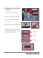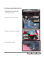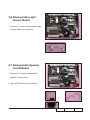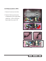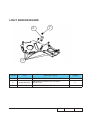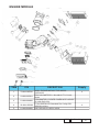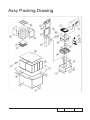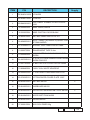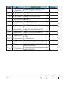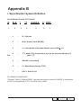
1
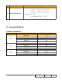
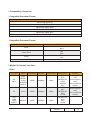
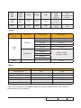
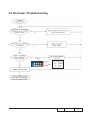
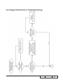
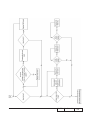
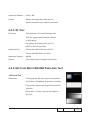
SERVICE MANUAL
ML500
Date
Revise Version
Description
2011.08.23
V1.0
Initial Issue
2011.09.5
V2.0
Modify Chapter 6 ,Chapter 3
2011.10.18
V3.0
Modify chapter 5,add new method to upgrade
multimedia FW
Copyright OCT. 2011 All Rights Reserved
Prepared: Chris Checked:
Amy
Approved: Alick
Preface
This manual is applied to ML500 projection system. The manual gives you a brief
description of basic technical information to help in service and maintain the product.
Your customers will appreciate the quick response time when you immediately identify
problems that occur with our products. We expect your customers will appreciate the
service that you offer them.
This manual is for technicians and people who have an electronic background. Please
send the product back to the distributor for repairing and do not attempt to do anything that
is complex or is not mentioned in the troubleshooting.
Notice:
The information found in this manual is subject to change without prior notice. Any
subsequent changes made to the data herein will be incorporated in future edition.
ML500 Service Manual
Copyright OCT. 2011
All Rights Reserved
Manual Version 3.0
ML500
Confidential
II
Table of Content
Chapter 1
Introduction
Highlight
1-1
Chapter 2
Compatible Mode
1-2
Disassembly Process
Equipment Needed & Product Overview
2-1
Disassemble Top Cover Module and Key Pad
2-2
Disassemble LED Driver Board
Disassemble Main Board
Disassemble Fan
Disassemble Light Sensor Board
Disassemble Speaker and IR Board
Disassemble Engine Module and LED
Disassemble LVPS
Disassemble Bottom Cover Module
2-11
Re-write LED Usage Hour
2-12
Repair Action
2-13
Chapter 3
2-4
2-5
2-6
2-7
2-7
2-8
2-10
Troubleshooting
Equipment Needed
3-1
Main Procedure
3-2
No Power Troubleshooting
3-3
Power Troubleshooting
3-4
Image Troubleshooting
3-5
ML500
Confidential
III
Remote Control Troubleshooting
3-9
Chapter 4 Function Test & Alignment Procedure
Test Equipment Needed
4-1
Test Conditon
4-1
I/O Port Test
4-2
Composite Port And Audio Test
4-7
S-Video Port Test
4-7
HDMI Port Test
4-7
3D test
4-8
SD Card /Mini USB/ USB flash disk test
Calibration
Chapter 5
4-8
4-10
Run in test
4-12
Test Inspection Procedure
4-13
Firmware Upgrade Section 1: System Firmware Upgrade
5-1
Equipment Needed
5-1
DLP Composer Lite Setup Procedure
5-2
Firmware Upgrade Procedure
5-4
Section 2: Multi-Media Firmware Upgrade(USB)
5-7
ML500
Confidential
IV
USB Driver Upgrade Procedure
5-8
Multi-Media Firmware Upgrade
Chapter 6
5-10
Section 3: Multi-Media Firmware Upgrade(SD Card)
5-13
Multi-Media Firmware Upgrade procedure
5-14
Section 4: 8051 Firmware Upgrade
5-17
Firmware Upgrade Procedure
5-18
EDID Upgrade
EDID upgrade procedure 6-1
Appendix A
Exploded Overview
Appendix B
Serial Number System Definition
X
PCBA Code Definition
XI
ML500
I
Confidential
VI
Chapter 1
Introduction
1-1 Highlight
No
Item
Description
1
Dimensions (WxDxH)
● 220x170x41 mm
2
Power Supply
● Auto-ranging: AC100V ~ 240V ± 10%, 50-60Hz
3
Power consumption
4
Keystone correction
● Vertical +/-40 degree
5
Throw ratio
●WXGA 1280x800 1.4 +/- 5%
6
Projection lens
● YM102
7
LED life
20,000 Hours Bright Mode @ 75W +/-10 % , B50/
L50*Note Survival Rate
8
DMD Chip
●TI” DMD , 0.45” WXGA DMD
9
System controller
● TI DPP6401
10
Throw Distance
●Normal mode: 120W +/- 20%.@ 110Vac
●ECO mode: 60W +/-20% @ 110Vac
0.52m ~3.00 m (mechanical travel range)
0.91m ~ 2.40 m (optical travel range)
Standards :
11
Video compatibility
● NTSC M/J, 3.58MHz, 4.43MHz
● PAL BG/DK/I/M/N , 4.43MHz
● 480i, 480p, 576i, 576p, 720p, 1080i
12
Input signal spec
● Analog RGB signal (PC)
- Analog RGB 0.7 +/- 0.1 Vp-p, 75 ohm
- Separate TTL H,V Sync.
● Video
������������
signal
- NTSC/PAL Composite video 1.0 +/- 0.1 Vp-p, 75ohm
● Audio
�������������
signal
- 900mVrms, 22K ohm
ML500
Confidential
1-
No
Item
Description
● Operating: 0 ~ 2,500 ft, for 5°C~35°C
13
Altitude&Temperature
2,500 ft ~ 5,000 ft, for 5°C~30°C
5,000 ft ~ 10,000 ft, for 5°C~25°C
● Operating: 5 ~ 35 °C
Non-operation:-20°C ~ 60°C
1-2 Compatible Mode
● Computer Compatibility
Compatibility
Resolution
V-Sync [Hz]
VGA
640 x 480
800x600
1024x768
1280x720
1280x800
60
60
60
60
60
480i/480p
60
576i/576p
720p
1080i/1080p
480i/480p
576i/576p
720p
1080i/1080p
50
50/60
50/60
60
50
50/60
50/60
Video
HDMI
ML500
Confidential
1-
● Compatibility: Document
- Compatible Document Format
Office Version
Microsoft® Office 95
Microsoft® Office 97
Microsoft® Office 2000
Microsoft® Office 2003
Microsoft® Office 2007
Microsoft® Office 2010
- Compatible Document Format
Microsoft® Office Application
File Extension
.doc
.docx
.ppt
.pptx
.xls
.xlsx
Word
Power Point
Excel
Adobe PDF
.pdf
● Media File Support List Video
- Video
File Type
Video
AVI
MKV
XVID
MPEG4
H.264
M-JPEG
WMV3
Resolution
1080P
Bit Rate
20Mbps
Frame Rate
30fps
TS
H.264
1080P
20Mbps
30fps
DAT
VOB
MPG
MPEG
MPEG-1
1080P
20Mbps
30fps
Audio Code
Remark
AC3
DTS
MPEG1/2/3
PCM
ADPCM
AAC
AC3
AAC
MPEG1/2/3
DTS
LPCM
MPEG1/2/3
AC3
DTS
LPCM
No support VC1 AP
H.264 support
less
than 4 reference
frames
ML500
H.264 support
less
than 4 reference
frames
Confidential
1-
MOV
MP4
3GP
MPEG-4
H.264
H.263
1080P
20Mbps
30fps
RM
RMVB
RV3
RV4
720P
5Mbps
30fps
WMV
WMV3
1080P
20Mbps
30fps
AAC
H.264 support
AMR
less
PCM
than 4 reference
ADPCM
frames
Cook(RA4)
AAC(RA9)
RACP(RA10)
WMA2
No support VCWMA3
1 AP
- Image
Image Type (Ext
name)
Sub Type
Baseline
JPEG
JPG
Encode Type
Max Pixels
YUV400
No Limit
YUV420
No Limit
YUV422
No Limit
YUV440
No Limit
YUV444
No Limit
YUV400
YUV420
Progressive
Width<=10240
& Height <= 6400
YUV422
YUV440
YUV444
BMP
No Limit
- Music
Music Type (Ext name)
Sample Rate (KHz)
Bit Rate (Kbps)
MP1/MP2/MP3
8-48
8-320
WMA
22-48
5-320
OGG
8-48
64-320
ADPCM-WAV
8-48
32-384
PCM-WAV
8-48
128-1536
AAC
8-48
8-256
Note: If the Computer Compatibility supportive signal is different from User’s Manual,
please refer to User’s Manual.
ML500
Confidential
1-
Chapter 2
Disassemble And Repair Action
2-1 Equipment Needed & Product Overview
1. Screw Bit (+) :107
2. Hex Sleeves 5mm
3. Screw Bit (+) :102
4. Hex Sleeves 7mm
5. Tweezers
6. ML500 unit
* Before you start: This process is protective level II. Operators should wear electrostatic
chains.
* Note: If you need to replace the main board, you have to get into service mode and
record the LED usage hour. please refer to section 2-12.
ML500
Confidential
2-1
2-2 Disassemble Top Cover
Module and Key Pad
1. Unscrew 4 screws on bottom side (as
red circle)
2. Disassemble the Top Cover (as red arrow direct).
ML500
Confidential
2-
3. Tear off the mylar
4. Separate the keypad and the Top Cover
Module.
ML500
Confidential
2-3
2-3 Disassemble LED Driver
Board
1. Unscrew 2 screws (as red circle)
2. Unplug 3 connectors (as red square)
3.Push the LED Driver Board (as red
arrow direct)
4.Unplug 1 connector (as yellow square)
5. Unplug 3 connectors (as yellow circle),
disassemble LED to LED Driver Board
GREEN LED
CABLE
cable and LED Driver Board.
RED LED
CABLE
BLUE LED
CABLE
LED Driver Board
ML500
Confidential
2-4
2-4 Disassemble Main Board
1. Disassemble
��������������������������������
2 hex screws on the
rear side(as red circle)
2. Unscrew 4 screws (as red circle)
3. Unplug 7 connectors (as red square)
4. Disassemble Main Board
Main Board
ML500
Confidential
2-
2-5 Disassemble Fan
1. Take off three Fans
Note: Care the direction about how to place
the fan (as yellow square).
ML500
Confidential
2-6
2-6 Disassemble Light
Sensor Board
1. Unscrew 1 screw to disassemble Light
Sensor Board (as red circle)
2-7 Disassemble Speaker
and IR Board
1. Unscrew 2 screws to disassemble
speaker (as red circle)
2. Take off IR Board (as red square)
ML500
Confidential
2-
2-8 Disassemble Engine
Module and LED
1. Unscrew 4 screws to disassemble
Engine Module (as red circle)
2. Unscrew 4 screws on the rear side of
the Engine Module to disassemble
DMD Module and Green LED(as
yellow circle),
DMD Board
ML500
Confidential
2-8
3. Disassemble the Green LED.
4. Unscrew 2 screws on the front side
of the Engine Module to disassemble
Red LED(as red circle).
ENGINE MODULE
ML500
Confidential
2-9
2-9 Disassemble LVPS
1. Unscrew 6 screws (as red circle)
2. Unplug 2 cables (as red square)
to disassemble LVPS to Main Board
cable(8 pin) , LVPS to LED Driver
Board cable(10 pin) and LVPS
LVPS
ML500
Confidential
2-10
2-10 Disassemble Bottom
Cover Module
1. Take off Mylar(as yellow square)
and Unscrew 1 screw (as red circle)
to disassemble Bottom Cover Module
ML500
Confidential
2-11
2-11 Re-write LED Usage
Hour
1. Get into service mode
- Press (power→left→left→menu) to get
into service mode
2. Choose "Other Settings"(As the red
square)
3. Choose "System Hours Adjust" to re-write
the usage hour back to previous usage
hour
4. Choose "LED Hours Adjust" to re-write
the usage hour back to previous usage
5. Choose "Return to Service Menu"
6. Choose Exit
Note: left key = decrease LED hour
right key =increase LED hour
ML500
Confidential
2-12
2-12 Repair Action
Repair Action
Change Parts
Main Board
System Firmware Update
V
PC Calibration
V
Engine Module
Software
LED
Fan
Firmware
V
Description page
EDID
V
V
Chapter 5 Section 1
V
V
Chapter 4-3-7
V
V
Chapter 4-7
OSD Reset
V
EDID
V
Chapter 6
Re-write LED
Usage Hour
V
Chapter 2-11
USB Port Test
V
V
V
V
Optical perfermance
Measure
LED calibration
V
G sensor calibration
V
Fan calibration
V
V
Chapter 4-3-7
Chapter 4-3-1
V
V
Chapter 4-3-7
V
Chapter 4-3-7
V
ML500
Chapter 4-3-7
Confidential
2-13
Chapter 3
Troubleshooting
3-1 LED Lighting Message
Power_LED
Power_LED
Red
Blue
Power Plug
ON->OFF->1 second->ON
-
Standby Mode
ON
-
Power button ON
Flash once
ON
Firmware download
ON
ON
Power button ON
Flash once
ON
Power off, Cooling state
0.5 second H(ON), 0.5 second
L(OFF) flashing
-
Power button OFF: Cooling completed; Standby Mode
ON
-
Thermal sensor error, OSD shows
“Projector Overheated”
-
ON
Fan lock error, OSD shows red
“Fan Fail, Will automatically turn
off soon”
-
ON
Message
ML500
Confidential
3-
3-2 Main Procedure
ML500
Confidential
3-
3-3 No Power Ttoubleshooting
pin 2
pin 1
pin 8
+5V
+5V
+5V
ML500 Confidential
3-
3-4 Power Troubleshooting
J8 pin1
J7 pin1
Pin 6
+12V
+12V
+12V
+12V
+12V
Pin 10
J9 pin1
pin8
ML500
Confidential
3-
3-5 Image Performance Troubleshooting
ML500 Confidential
3-
ML500
Confidential
3-
ML500 Confidential
3-
ML500
Confidential
3-
3-6 Remote Control Troubleshooting
ML500 Confidential
3-
Chapter 4
Function Test & Alignment Procedure
4-1 Test Equipment Needed
-PC
- DVD player with Multi-system, equipped "Component", "S-Video","Composite"
and "HDMI".
- HDTV Source (480P, 720P, 1080i, 1080P)
- Minolta CL-200
- Quantum Data 802B or CHROMA2327 (Color Video Signal & Pattern Generator)
4-2 Test Condition
- Circumstance brightness: Dark room less than 2.0 lux
- Product must be warmed up for 3 minutes.
- Screen size: 30 inches
Zone Definition
< Figure: Zone A&Frame (as green line) Definition >
ML500
Confidential
4-
4-3 I/O Port Test
4-3-1 VGA Port Test
Note: - When doing function test, get in to service mode,choose “lenstop”, press enter,
adjust the lens to the highest state and then adjust “Zoom” and “Focus” to guarantee
the image maximum and clearest,then start test.
1. Frequency and Tracking Boundary
Procedure
-Test equipment: video generator
- Test signal: 1280*800@60Hz
- Test Pattern: Master
- Check and see if the image sharpness is well
performed.
- If not, re-adjust by the following steps:
(1) Select “Frequency” function to adjust the total
pixel number of pixel clock in one line period.
(2) Select “Tracking” function and use right or left
arrow key to adjust the value to minimize video
flicker.
Master
- Adjust Resync or Frequency/Tracking/H. Position/
V. Position to the inner screen.
Inspection item
- Eliminate visual wavy noise by Resync, Frequency
or Tracking selection.
- Check if there is noise on the screen.
- Horizontal and vertical position of the video should be
adjustable to the screen frame.
ML500 Confidential
4-
Criteria
- If there is noise on the screen, the product is
considered as failure product.
- If there is noise on the screen, use auto or manual
“frequency” function or “tracking” function to
adjust the screen.
- The PC mode functionally sure be workable
include support format with frequency and auto
detected functional will be workable.
2. Bright Pixel
Procedure - Test equipment: video generator
- Test signal :1280*800@60Hz
- Test Pattern: Full black
Inspection item
-Bright pixel check
Criteria
- Adjacent pixels are unacceptable.
- If there is blemish on full black pattern,
Full Black
please use gray 10 pattern to judge it.
-Please refer to Pixel specification table.
3. Dark Pixel
Procedure - Test equipment: video generator
- Test signal: 1280*800@60Hz
- Test Pattern: Full white
Inspection item
- Dark pixels check
Full white
ML500
Confidential
4-
Criteria
- Adjacent pixels are unacceptable.
- Please refer to Pixel specification table.
4. Bright Blemish
Procedure
- Test equipment: video generator
- Test signal: 1280*800@60Hz
- Test Pattern: Gray 10
Inspection item
- Bright blemish check
Criteria
- Please refer to Pixel specification table.
Gray 10
5. Dark Blemish
Procedure
- Test equipment: video generator
- Test signal: 1280*800@60Hz
- Test Pattern: Blue 60
Inspection item
- Dark blemish check.
Criteria
- The dark blemish should be no more than 10
under blue 60 pattern.
Blue 60
- Please refer to Pixel specification table.
ML500 Confidential
4-
Pixel specification
Order
Symptom
Pattern
Black pattern
Criteria
1
Bright pixel ( dots)
2
Dark pixel(dots)
White pattern
A≤1
3
Bright blemish
Gray 10 pattern
A =0
4
Dark Blemish
Blue 60
A =0
5
Bright dot on frame
Black pattern
≤1
6
Unstable pixel
7
Adjacent dark pixel
( IRE=O)
White & Black pattern
White & Black pattern
A=0
A≤1
A=0
6. Focus Test
Procedure - Test equipment: video generator
- Test signal: 1280*800@60Hz
-Test Pattern: Full screen
Inspection item
- Focus check
Criteria
-From screen 1.0M via visual to check the focus, look
Full Screen
at the entire screen, focus shall be clear, crisp, and
sharp over the entire surface of the display pattern.
(Blur word on one of the corner after adjustment is
A OK
acceptable. However, the word should at least
be recognizable.)
Note:After adiust the focus , if the screen appear as picture A will be
regarded as OK .Otherwise , if the screen appear as picture B will
B NG”Poor”
be adjudicated as NG.
ML500
Confidential
4-
7. Color Performance
Procedure - Test equipment: video generator
- Test signal: 480p, 720p, 1080p
- Test Pattern: Master, 64 gray RGBW or 32GRAYS
*Please get into service mode.
Use 720p & 1080p signal, master pattern to do HDTV
Master
test. Color should not discolor to purple
����������������
and blue.
Inspection item
- Check if each color level is well-functioned.
- Color saturation
Criteria
- Screen appears normal. It should not have any
64GRAYS RGBW
abnormal condition, such as lines appear on the
screen and so on.
-������������������������
Color appears normal.
- It is unacceptable to have few lines flashing.
- RGBW should all appear normal on the screen
32GRAYS
and sort from R -G-B-W.
- Color levels should be sufficient and normal.
(The unidentified color levels on both left and
right sides should not over 4 color levels.)
- Gray level should not have abnormal color or
heavy lines.
- If color appears abnormal, please get into
service mode to do LED Calibration.
ML500 Confidential
4-
4-3-2 Composite Port And Audio Test
Procedure
- Test equipment: DVD player
- Test signal: CVBS
Inspection item
- Video performance test
Inspection Distance
- 0.8M-1.0M
Criteria
- Check any abnormal color, line distortion
Motion video
or any noise on the screen.
- Check if the sound from speaker.
- Check if “Volume” and “Mute” functions are normal.
4-3-3 S-Video Port Test
Procedure
- Test equipment: DVD player
- Test signal: S-Video
Inspection item
- Video performance test
Inspection Distance
- 0.8M-1.0M
Criteria
- Check any abnormal color, line distortion or
any noise on the screen.
4-3-4 HDMI Port Test
Procedure
- Test Signal : 720p,1080i
- Test Pattern : Any Pattern
- Equipment: DVD Player with HDMI output
- Display type must be set to 16:9
Inspection item
- HDMI Test
ML500
Confidential
4-
Inspection Distance
- 0.8M -1.0M
Criteria
- Ensure the image and sound are well
performed and the color should not discolor.
4-3-5 3D Test
Procedure
- Test equipment: PC with 3D display card,
DLP 3D goggles and 3D player software
or DVD player.
- Test signal: 3D Format movie (for PC)
HQFS format CD (for DVD)
Inspection item
- 3D test with 120Hz VGA port (for PC)
3D test with 480i Video (for DVD)
Inspection Distance
- 3M-5M
Criteria
- The image should not appear noise,flicker.
4-3-6 SD Card/ Mini USB/USB flash disk Test
1.SD Card Test
Procedure
- Test equipment: SD Card (include test pattern)
- Test Pattern: WhiteBlack ,Graystep16, ColorBar
- Turn on the projector and plug SD Card into the
projector.
- Select “SD”-->”Photo”, play the test pattern in
WhiteBlack_640x480
SD Card.
GrayStep16_640x480
ML500 Confidential
4-
- Press “
” button on remote controller
when the image is at WhiteBlack test pattern.
- Get into service mode.
ColorBar_640x480
2.USB flash disk Test
Procedure
- Test equipment: USB flash disk(include video
file).
- Test Pattern: video file.
- Turn on the projector and plug USB flash disk
into the projector.
- Select “USB”-->”Video”, then play video file
in USB flash disk.
Inspection item
- Check any abnormal color, any noise on
the screen.
- Check the sound from speaker.
Criteria
- The video is played smoothly and the voice
sounds normal.
3.Mini USB Test
Procedure - Test equipment:Mini USB
- Test Pattern: video file.
- Turn on the projector and plug Mini USB cable into
the projector.
- Select “menu”-->”mini USB”-->”USB display”
Inspection item
- Check any abnormal color, any noise on the screen.
- Check the sound from speaker.
Criteria
- The video is played smoothly and the voice
sounds normal.
ML500
Confidential
4-
4-4 Calibration
1.PC Calibration
To adjust the white/black value of VGA signal,after replacing main board
or upgrading firmware, the “PC calibration” is needed:
Procedure
- Test equipment: video generator
- Once Main Board or FW is changed, PC
Calibration should be done as well.
(1) Test signal analog: 1280*800@60Hz
(2) Test Pattern: White (up) Black (down)
White/Black
- Note:(1) Calibration pattern should be in full screen mode.
(2) Please press "Power", "Left", "Left" and "Menu" buttons
sequentially to get into Service Mode.
(3) Choose "Analog Settings", press "Menu" button to access
"PC Calibration" for correction. When the message "Success"
appears, it means "PC Calibration" is OK. Choose "Exit" to
leave the Service Mode.
Check pattern
- Test signal: 1280*800@60Hz
- Test pattern: 64 gray RGBW
* After finishing ADC adjustment, check 64 gray
64 gray RGBW
RGBW pattern.
Inspection item
- Color saturation
Criteria
- There should not have any lack of RGBW.
The color should appear normal and sort in right order.
- Color levels should be sufficient and normal.
(the unidentified color levels on both left and
right sides should not over 8 color levels.)
ML500 Confidential
4-10
2. Fan Calibration
To store the value of fan in main board, after replacing main board, blower
or upgrading the firmware, the “Fan calibration” is needed:
Procedure
- Hold on “Menu” button then plug in Power Cord .
- Power LED will flash red and blue .
- Release “Menu” button once Power LED flashes
red blue only.
- The Projector will power on.
- After about 30s, get into Service Mode to check
the fan speed has been recorded.
3. LED Calibration
Note:After replacing main board, Engine Module , if the color abnormal,
you can do the “LED calibration” .
1.Procedure
- Press “Power”-->“left”--> “left”-->“Menu” to get
into Service Mode.
- Select “LED Calibration Setting”
- Enter in LED Calibration Settings , and select
“Reset Calibration Data”
2.If the color appears abnormal, please execute below procedure:
- Put the CL200 on the center of the screen which
- Put the CL200 on the center of the screen which
is about 0.8~1.0m far away from projector
- Connect LED Calibration Fixture and Projector
by VGA Cable.
ML500
Confidential
4-11
- Connect LED Calibration Fixture and CL200
CL200 RS232 Cable
by CL200 RS232 Cable.
- Connect LED Calibration Fixture and Computer
by
�������������
USB Cable.
- Power on the projector and get into Service Mode.
- Press "LED Calibration Setting"
Must be on the center of the screen
USB Cable
VGA Cable
- Press "LED Calibration" to start calibration and
"success" will appear in right blank.
CL200 RS232 Cable
4. G Sensor Calibration
To keep the balance of screen, after replacing main board, the “G
Sensor calibration” is needed:
Procedure
- Please put the Projector on a horizontal surface.
- Please press "Power", "Left", "Left" and
"Menu" buttons sequentially to get into Service Mode.
- Press "G Sensor Calibration" for correction.
4-5 Run In Test
- Temperature: 29°C~35°C
- Circumstance brightness: Normal environment
- Screen size: No concern
- Display mode: ECO mode
- After repairing each unit, it should be Run-in (refer to the below table).
Symptom
Normal repair
Run-in Time
2 hours
NFF
Auto shut down
4 hours
6 hours
ML500 Confidential
4-12
- Get into Burn-In Mode
* Cycle setting is based on the defect symptoms. ie: If it is NFF, the run-in
time is 4 hours. You have to set the LED on for 60 min. and LED off for
15 min for 4 cycles.
Note: Please make sure that the hot exhaust airflows from projectors can
flow towards the aisle.
Press power > Left > Left > menu to get into service mode
Choose Burn-In Test > enter
LED On
Press right key to adjust the time (60)
LED Off
Press right key to adjust the time (15)
Set burn in cycle
Press right key to adjust the cycle
After setting up the time, choose “Get into Burn-In Mode” and press enter
4-6 Test Inspection Procedure
1. Check Points
Check item
Check point
Firmware version
All firmware version must be the lastest version
TB implementation
Related TB must be implement
Cosmetic
Cosmetic can not be broken
Logo
Missing logo, missing prints and blurry prints are
unacceptable
Zoom in/out
The function should work smoothly
Keypad
All keypad buttons must operate smoothly
ML500
Confidential
4-13
2.OSD Reset
After final QC step, we have to erase all saved change again
and restore the OSD default setting. The following actions will
allow you to erase all end-users' settings and restore the
default setting:
(1) Please get into OSD menu.
(2) To execute "Reset" function.
ML500 Confidential
4-14
Chapter 5
Firmware Upgrade
Section 1: System Firmware Upgrade
5-1-1 Equipment Needed
Software : (DDP6401-USB)
- DLP Composer Lite v10.5
- Firmware (*.img)
- library (ML500 library)
Hardware :
- Projector
- Power Cord
- USB Cable mini USB to USB (A) (42.00284G001)
- PC or Laptop
ML500 Confidential
5-
5-1-2 D L P C o m p o s e r L i t e
Setup Procedure
1. Choose "DLP Composer Lite V10.5 Setup"
Program.
2. Click Next button.
3. Read License Agreement.
-C
hoose" I accept and agree to be bound
by all the terms and conditions of this
License Agreement".
- Click Next.
4. Click "Next".
ML500
Confidential
5-
5. Click Next.
6. Click Next.
7. Click Finish.
8. Restart the computer.
ML500
Confidential
5-
5-1-3 Firmware Upgrade
Procedure
1. Set-up
- Hold on "Power" and "menu" and plug in
Power Cord to get into FW Download
Mode.
- Once Power LED show pink light,this time
for FW upgrade mode.
- Insert Mini-USB Cable (USB A to Mini B)
to ML500&PC
2. Execute the DLP Compose file.
3. Click "edit" and "perferences".
ML500
Confidential
5-
4. Click “Library.”
- Click the “browse” button and navigate to
the directory where you put the library file
in.
5. Click "Communications ",then select "USB"
6. Choose "Flash Loader".
- Click "Browse" to search the firmware file
(*.img).
- Click "Open"
ML500
Confidential
5-
7. Selete the item skip Boot Loader Area
- Select "32KB".
- Click Reset Bus to erase the flash
memory.
8. If the firmware is ready, click start download
to process the firmware upgrade.
- Click “Yes” to erase the flash memory.
9.When firmware upgrade process is finished,
“Download Complete” will appear.
10.Re-plug in power cord and Power on
the projector. Get into the service mode
(power--left--left--menu) to check
the firmware version.
ML500
Confidential
5-
Section 2 : Multimedia FW Upgrade(USB)
5-2-1 Equipment Needed
Software :
- Firmware (*.Bin)
- Tools
Hardware :
- Projector
- Power cord (42.53506G002)
- USB Cable (male to male)(42.0028JG001)
- PC or Laptop
Note:After upgrade the multimedia FW, the files of the projector will be cleared.
ML500
Confidential
5-
5-2-2 USB Driver Upgrade
Procedure
1. Set up
- Hold on "Power" and "menu" and plug
in Power Cord to get into FW Download
Mode.Once Power LED lights pink,
then release "Power" and "menu"
button.
- Plug in USB cable into the projector and
link to the USB port of a PC.
2. Execute Program
1) F
ound new hardware wiszard will
appear on the screen.
- Select “Install from a list or specific
location (Advanced)”
- Then click Next.
2) Select “Include this location in the
search”
ML500
Confidential
5-
3) Click "Browse" button to choose
"tools".
- Select “OK”.
- Then click Next.
4) Click "Continue Anyway".
5) Click "Finish" to end the
installation.
ML500
Confidential
5-
5-2-3 Multi-Media Firmware
Upgrade Procedure
1. - Open "tools" file,
- Execute “Actions MP Update.exe”.
2. - Click "Firmware",
- Select the FW upgrade file(*.bin),
- Click "Open".
ML500
Confidential
5-10
3. Click “Download.”
4. The success information will show on
screen.
ML500
Confidential
5-11
5. Restart the unit and enter the service
mode to check the Multi-Media firmware
version.
ML500
Confidential
5-12
Section3:Multimedia FW Upgrade
(SD Card)
5-3-1 Equipment Needed
Software :
- Firmware (*.Bin)
- Tools
Hardware :
- Projector
- Power cord (42.53506G002)
- PC or Laptop
- Card Reader
- SD Card
Note:After upgrade the multimedia FW, the files of the projector will be cleared.
ML500
Confidential
5-13
5-3-2 Multi-Media Firmware
Upgrade Procedure
1.Rename multimedia software file name to “
ACTUPGRADE.BIN”.
2.Copy the file to SD card by PC.
3.Insert SD card to projector.
4.Choose "Setup"
ML500
Confidential
5-14
5.Choose "System"
6.Choose"Firmware Upgrade"
7.Choose "Yes" to process FW Upgrade .
ML500
Confidential
5-15
8.Firmware upgrade procedure image will
appear as the right picture shown.
9.Restart the unit and enter the service
mode to check the Multi-Media firmware
version.
ML500
Confidential
5-16
Section 4: 8051 FW Upgrade
5-4-1 Equipment Needed
Software: (N79A901R-USB)
- Setup _NLINK_en
- Manley USB Driver_NLINK
- xxx_8051_xx.hex
Hardware:
- Projector
- Power cord: 42.50115G001
- USB Cable mini USB to USB (A) (42.00284
G001)
- NLINK Fixture
- PC or Laptop
ML500
Confidential
5-17
5-4-2 8051 Firmware
Upgrade Procedure
1. Set-up
- Plug in USB cable into the projector and
link to the USB port of a PC
- Connect VGA Port of projector with
NLINK Fixture.
- Connect NLINK Fixture with PC by USB
cable.
2. Execute 8051 FW Program
- Double click “NLINK V1.2” to execute
NLINK program.
3. Choose the right type of MCU
- “MCU Choose” picture will appear on the
screen, select "N79A901R."
- Click “OK”.
4. Program settings
Ensure NLlNK Fixture and PC are
securely connected: the indicator lights
on green, and the state is “Connect”
(as blue square).
- Select “Brownout Level 3.8V” (as green square).
- Select “Internel RC(11.0592MHz)” (as
green square).
- Click “Erase/Write(W)” to execute
8051 FW upgrade (as red circle).
ML500
Confidential
5-18
5-4-3 Check 8051 FW version
1. Restart the unit and enter the Service Mode
(Press Power --> Left --> Left--> Menu).
2. The firmware version will be shown as red
circle on the screen.
ML500
Confidential
5-19
Chapter 6
EDID Upgrade
6-1 EDID Introduction
Extended Display Identification Data is a VESA standard data format that contains basic
information about a display device and its capabilities, including vendor information, maximum
image size, color characteristics, factory pre-set timings, frequency range limits, and character
strings for the monitor name and serial number.
The information is stored in the display and is used to communicate with the system through a
Display Data Channel (DDC), which sites between the display device and the PC graphics adapter.
The system uses this information for configuration purposes, so the monitor and system can work
together.
Note: If a display device has digital input ports, like DVI or HDMI, but without EDID in its
main board, the display device will show no image while the input source is digital
signal.
ML500
Confidential
6-
6-2 Equipment Needed
Software
- EDID Program (Generic V0.81)
- EDID File (*.ini)
Hardware
- Projector
- Generic Fixture (80.00001.001) for EDID Key-in
- Power Cord
- RS-232 9 Pin Cable (pin to pin, F-M) (42.83C07G001)
- Monitor
- PC
- VGA cable (42.87305G102)
- Power adapter (47.57803G001) and power cord (42.53506G002) for fixture
- HDMI to DVI Cable(42.00256G001)
ML500
Confidential
6-
P2
6-3 Setup Procedure
P1
1. Connect all ports
(1) Connect P1 of Fixture with COM Port of
P3
PC/Laptop by RS232 Cable.
(2) Connect P2 of Fixture with VGA port of
Projector by VGA Cable.
Power CNN
(3) Connect P3 of Fixture with DVI port ,and connect
HDMI port of Projector.
(4) Plug Power Adapter to Power CNN.
(5) Plug power cord to ML500 unit.
2. EDID Firmware Mode
(1) Hold the “Power” button to plug Power Cord to
ML500 unit.
Power Port HDMI Port VGA Port
(2) When the “Power LED” flashes blue, release
the “power” button.
(3) When the “Power LED” flash alternates red with
blue, it means the projector has got into EDID
FW mode.
ML500
Confidential
6-
6-4 EDID Key-In Procedure
1. Execute EDID Program
1
(1) Click on "EDID" to execute EDID
program.
2. Process
(1) Check the COM port is COM1"
2
(Select the COM port which you are
using).
(2) Click the Model button.
(3) Choose the source file "*.ini" and then
open it.
3
3. Process
(1) Key in the serial number into the
barcode blank space.
(2) Click "Program" button.
(3) - "Please change the cable to VGA"
will be shown on the screen.
- Please press "Ok" button.
ML500
Confidential
6-
4.- "Please change the cable to HDMI" will be
4
shown on the screen.
- Please press "OK" button.
5. Finish
5
(1) "OK" will be shown on the screen.
6
6. Read EDID "Analog" information
(1) In the Read item,select "Analog" and
"Trans".
(2) Please click "Read" .
(3) EDID “Analog” information will show
the result.
ML500
Confidential
6-
7. Read EDID "Digital"information
(1) In the Read item,select "Digital" and
"Trans".
(2) Please click "Read" .
(3) EDID “Digital” information will show
the result.
ML500
Confidential
6-6
Appendix A (Explode Image)
DC. ML500
16
14
15
13
ML500 Confidential
I
ITEM
P/N
DECRIPTION
1
70.8LK04GR01
2
75.8LK02G001 8LK TOP COVER MODULE
3
80.8KU05G001
Supply
ASSY ENGINE MODULE FOR
ML500(SERVICE)
V
V
PCBA FRONT IR SENSOR BOARD FOR
K330 PROJECTOR
8LK BOTTOM COVER MODULE
LVPS MYLAR PLED-W500
8LK KEY BUTTON MODULE
FOCUS RING ABS FOR ML500
FAN RUBBER BLACK K330
ML500 SPONGE 125*15*0.95mm
8
75.8LK01G001
51.8KU08G002
51.8LK01G001
51.8MA06H011
52.8KU02G001
9
52.8LK02G001
10
61.8MA02H001 SPEAKER BRACKET SECC PLED-W500
PCBA MAIN BD FOR ML500
80.8LK01G002
[PROJECTOR]
PCBA LED DRIVER BD LT3743 TYPE FOR
80.8KU07G011
K330 PROJECTOR
ASSY YGE CT-P120 LVPS FOR K330 LED
75.8KU01GP03
500lm
DELTA 35X35X15 AXIAL FAN
49.8KU11G001
LENGTH=120mm
49.8FS01G001 DELTA 35*15 AXIAL FAN
49.8KU01G001 SPEAKER MINI 2W 4ohm 100mm K330
4
5
6
7
11
12
13
14
15
16
ML500 Confidential
V
V
V
V
V
V
V
II
LIGHT SENSOR BOARD
2
1
3
ITEM
P/N
1
85.1A622G040
2
3
DECRIPTION
Supply
SCREW PAN MECH M2*4 BLACK NYLOK
PCBA LIGHT SENSOR BD FOR K330
80.8KU04G001
PROJECTOR
85.1A121G040 SCREW PAN MECH M1.7*4 Ni
ML500 Confidential
V
III
ENGINE MODULE
12
11
9
10
1
13
14
ITEM
P/N
1
70.8LK04GR01
2
23.8KU20G011
3
51.8KU20H001
4
23.8KU15G002
5
61.8KU02H001
DECRIPTION
Supply
ASSY ENGINE MODULE FOR ML500
(SERVICE)
D52 COLLIMETER C1 S-LAM 60 T7.1 D14.2,
Kinko
COLLIMATOR 1 COVER C1NEW A PC+20%GF
G-3420 ENG D52
PT54,GREEN LED,Standard Die Config,D52
400LM,Luminus
HS FIXPHOLD G SECC K330
ML500 Confidential
V
V
IV
ITEM
P/N
6
7
61.8KU03H001
61.8KU04H001
8
23.8KU15G001
9
61.8KU05H002
10
23.8KU15G003
11
12
52.8KU10G001
51.8MA06H011
13
48.8KU01G001
14
80.8KU02G001
DECRIPTION
Supply
HS CLAMP G SUS K330
HEAT PIPE MODULE GREEN C1NEW K330
PT54,RED LED,Standard Die Config,D52
400LM,Luminus
HEAT PIPE MODULE RED C1NEW K330
PT54,BLUE LED,Standard Die Config,D52
400LM,Luminus
RUBBER Projection Lens ENG D52
FOCUS RING ABS FOR ML500
DMD 1140x910 PIXEL 0.45” WXGA DDR Type
Series 310 DMD “TI”
PCBA DMD BOARD FOR K330 PROJECTOR
ML500 Confidential
V
V
V
ADJUST FOOT
ITEM
1
2
P/N
52.8FS02H001
86.00122G015
DECRIPTION
Supply
ADJUST FOOT K11
NUT HEX M2.0*0.4P L15 Ni
ML500 Confidential
VI
Assy Packing Drawing
ML500 Confidential
VII
ITEM
1
P/N
DECRIPTION
Supply
DC.8LK01G00A D.C.ML500
DP.8LK01G00A D.P.ML500
SPEC LABEL TLSM#50 70*48*0.2 PLEDW500
2
35.8MA02G001
3
35.00040G001 LABEL 30mm,GREEN
4
35.52302G091 LABEL CARTON 108*92 BLANK
5
35.86301G031 UNIT BOX LABEL WHITE PK-101
6
35.80N05G001
7
51.0000AG011 PACKING TAPE 72MM FOR OPTOMA
8
51.00037G001 TRANSPARENT TAPE 2.4cm
9
10
PALLET LABEL (W)100mm X(H)53mm FOR
OPTOMA MODEL
PACKING STRAP 13.5MM*1500M*0.7MM
GREEN
PE STRETCH FILM 500MM*1500M*0.02MM
51.00070GC01
GREEN FOR CPC
51.00069G001
11
51.00174G002 PE BAG 380*310*0.07mm FOR OPTOMA
12
51.86848G001 3 INCH*100m WHITE ADHESIVE
13
55.83R03G002 L TYPE PAPER 1190x1000x1350 EP747
14
55.87202GC01 BOTTOM PAPER COVER PLATE 1230*
15
55.8LK01G001 UNIT BOX ML500
16
55.8LK02G001 CARDBOARD ML500
17
55.8LK03G001 CARTON OUTSIDE BOX AB FLUTE ML500
18
55.8LK04G001 PAPER PARTITION ML500
19
56.8LK01G001 AIR BAG ML500
20
57.00001G001 PACK SIO2 DRIER 20g
V
ML500 Confidential
V
VIII
ITEM
P/N
DECRIPTION
Supply
21
58.54603G002
22
58.54604G001 COVER PALLET 120*100cm FOR COMPAQ
23
52.8KU01G001 RUBBER FOOT BLACK K330
NEW WOOD PALLET120*100*13cm
(DOUBLE FACE) FOR COMPAQ
AK.8LK01G00A A.K.ML500
24
35.82001G111 AK LABEL 3”*3” BLANK
25
42.50115G001
26
42.00200G005 CABLE VGA 15P 1.8M BLK EP739
V
27
45.8LK01G001 REMOTE CONTROL FOR ML500
V
28
51.80135G002
29
53.8LK01G001 SOFT BAG ML500
30
36.8LK01G001 QUICK START CARD MULTILINGUAL
31
36.00024G021
32
CABLE POWER CORD 1.8M SP30+IS14
US
V
PE BAG ZIPPER 240*170*0.04 #8 FOR
OPTOMA
V
WARRANTY CARD US FOR OPTOMA, 1
YEAR W/O BATTERY
INSTRUCTION CARD (OPTOMA)-BEFORE
36.00040G011
RETURN FOR PICO
ML500 Confidential
IX
Appendix B
I. Serial Number System Definition
Serial Number Format for Projector
Q
8LK
1
2
1
3
17
AAAAA
4
5
C 0001
6
7
1
:
Q = Optoma
2
:
8LK = Project Code (ML500)
3
:
0 = Last number of the manufacture year (ex:2011 = 1)
4
:
17 = week of the manufacture year (ex:the seventeenth week of
the year = 17)
5
:
AAAAA = not-defined
6
:
C = Manufacture factory (CPC)
7
:
0001 = Serial Code
EX: Q8LK017AAAAAC0001
This label "Q8LK117AAAAAC0001" represents the serial number for ML500. It is produced
at CPC on seventeenth of 2011. Its serial code is 0001.
ML500 Confidential
II.
PCBA Code Definition
PCBA Code for Projector
A B
1
XXX
XXXXXXXXX CC
3
2
4
5
XXX EEEE
6
7
1
1
:
ID
2
2
:
Vendor Code
33
:
Firmware Version
4
4
:
P/N
5
5
:
MB Version
6
6
:
Date Code
7
7
:
S/N
ML500 Confidential
XI