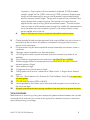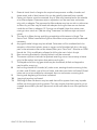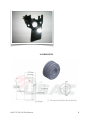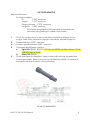
1
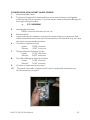
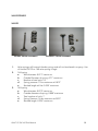
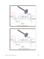
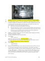
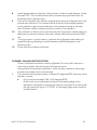
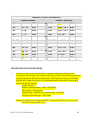
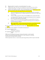
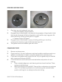
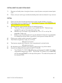
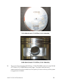
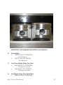
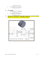
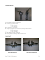
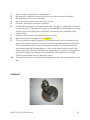
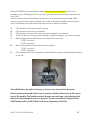
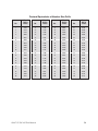
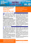
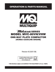
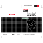
HONDA 160 UT1
TECH MANUAL
USAC NATIONAL TECH DIRECTOR
ERIC RANKINE
FEBRUARY 15, 2015
2015 UNITED STATES AUTO CLUB
HONDA GX 160 UT1 - TECH MANUAL
Updated February 22, 2015
FROM 2015 USAC NATIONAL .25 MIDGET RULE BOOK, APPENDIX I
731 Engine Protest Rules (applies to Honda and Briggs classes only)
1.
2.
3.
4.
5.
6.
7.
Protest shall be from within the same division of class only, i.e. Jr., Sr., Lt.& Hvy.
120-160, Animal or World Formula only. Competitors in the same division, and in
the same race may make a protest on an engine. No protesting in Rookie Class.
Handlers may not protest more than one car per event and may not protest same
driver more than once per calendar year.
Honda Engines and World Formula/Animal Engines may be protested for $400.00
cash only plus any applicable shipping charges if necessary. No protested related
inspection will be started prior to the funds being posted with the proper official.
This protest form and cash must be submitted to the Chief Steward, or his/her
designee, before the end of the race that the protested engine is participating in
I.E. Checkered flag lap complete.
The protest can only be made during an A-Main event.
The person protesting the motor must have their engine inspected for compliance
first. If the “protester’s” engine is found illegal the protest is null and void and the
protest fee will go to the club. If the “protester’s” engine is found legal the protest
will continue.
The Chief Steward, his/her designee, will hold the protest money until the
protested engine has been inspected for legality. The protested engine shall be
tagged/marked and sealed as soon as it car comes across the scale if it has not
been sealed prior.
The protested engine as well as the engine of the protested party shall be
immediately taken to impound and/or presented to the Tech Director for
inspection. Engine must remain in impound and in the possession of tech officials
throughout the entire process, including shipping to USAC Headquarters or
designated tech inspection station and the transferring of funds.
USAC .25 GX 160 Tech Manual
2
8.
9.
10.
11.
12.
13.
14.
Both protester and protestee have the option to be present at the time of
inspection.
Any protest that is withdrawn will be assessed a $50.00 fee that will be paid to the
host club.
If the protested engine is found to be illegal, the motor must be completely torn
down to check for additional illegalities. The Tech Director must confiscate all
illegal parts and related parts from the protested engine and shall immediately
forward them to the USAC Headquarters. If engine is found illegal protest money
minus $50 plus any shipping cost will be returned to the person filing the protest.
Refusal of protest, destroying or withholding of parts or any other lack of
cooperation in this protest or inspection process shall be interpreted as an
admission that the engine is illegal and shall subject the driver and handler to the
conditions set forth in the Suspensions Program.
Any teched or protested engine, block or part which are deemed to be over
maximum wear limits in one or more spots but is under maximum wear limits in
other spots is subject to confiscation but not DQ’able.
Note: Reference to Confiscation due to Wear Limits in “Engine Block Internal
Rules” of both Manuals.
If the engine is found legal $400 will be given to the person whose engine was
protested.
732 Engine Suspension Rules
Handlers and drivers guilty of having an engine declared illegal at technical inspections
shall be disciplined as
follows:
1.
2.
3.
4.
5.
6.
First offense – up to 30-days and/or 4 race suspension for handler and driver from
participating in the respective class at any USAC Sanctioned event.
Second offense within one year of first infraction – up to One-year suspension for
handler and driver from participating in the respective class at any USAC
Sanctioned event.
Third offense within two years of last infraction – Suspended for life from USAC’s .
25 Midget division.
Suspension for life is open to review by USAC.
Suspension shall begin immediately.
Illegal Honda, Animal and World Formula part/s shall be sent within five Business
days to the USAC office or designee for review. The Tech director has 48 hours to
determine if the part/s are legal or illegal. If the part/s are determined to be legal
it shall be returned to handler. Handler shall be notified if part/s are legal or illegal.
USAC .25 GX 160 Tech Manual
3
7.
8.
9.
10.
11.
12.
13.
All illegal or confiscated part/s shall be sent to National Tech Director. All legal
parts shall be returned to handler.
If a Honda motor is found to have a valve oil seal during tech it shall be a race
disqualification only.
Spark plugs and exhaust infractions are a race disqualification only.
Failure to go to tech and/or impound will result in a race day DQ. Refusal of tech
shall be interpreted as an admission that the engine is illegal and a suspension
from the class shall be immediate with all awards and qualifications being revoked
with a six-month suspension driver and handler suspension at any USAC
Sanctioned event.
For the purpose of this rule only, if a handler has multiple cars competing at one
race event and more than one engine is found to be illegal at that event; it will be
considered to be one offense.
All membership suspensions must be sent to the National Tech Director within 5
Business Days.
Illegal Rookie engine parts shall be confiscated (Honda or Animal) but the
suspension shall not be levied against handlers or drivers for the first offense. The
second offense shall result in a 30 days Suspension from Rookie.
The cost to appeal a suspension is $175 plus any associated fees. The appeal
must be made within 3 days of the ruling.
Unless it says you can do it you cannot do it!
GENERAL RULES
1.
2.
Only stock Honda GX160K1 HX2, HX26 engine and gearbox will be used in this
class. All parts will be stock Honda specifically made for the Honda GX160 OK1
HX2, U.S. GCAAK, and Canada # GCABT. Honda OEM 160 replacement block
12000-Z0T-406 may be used. Must be an OEM Honda replacement block. No
aftermarket blocks or components.
a.
All 160 Honda engines must be updated to the new E2 Style piston and
cylinder head.
b.
Failure to update + DQ and minimum 6 month suspension.
All stock Honda parts must be used and properly installed with the following
exceptions:
a.
Governor system may be partially or fully removed with the exception of the
steel drive gear on the crankshaft. This gear must remain intact. If shaft is
removed, hole must be plugged. Hole can be tapped for thread or epoxy.
No welding.
USAC .25 GX 160 Tech Manual
4
b.
3.
4.
5.
6.
7.
Factory air cleaner must be removed. Any air filter may be attached to the
outside of air filter adapter. Outerwear style or equivalent can be used over
carburetor only with no adapter. The approved air filter adapter may be run
with or without an air filter. Any air filter may be used with adapter as long
as there are no devices inside the air filter or adapter. (I.E. Springs not
allowed) hose from valve cover must go into a catch can. We are using
“outerwear” to define a style not brand name).
The use of air filters during qualifying at asphalt and dirt events is illegal. The
Senior Tech Official reserves the right to allow filters at any event that it’s deemed
necessary.
Any type of throttle linkage may be utilized. Carburetor shall remain unaltered
with the exception of the black plastic piece on the upper end of the throttle shaft.
This is the ONLY part of the carburetor that may be altered, removal of material
from the black plastic piece is allowed. No additional material may be added to
the carburetor. i.e. bolt in black plastic piece or tubing on throttle stop.
Stock Honda fuel tank must be removed.
Recoil starter must be removed. Pull cup may be cut down for washer. Must use
original cup.
Exhaust:
a.
Stock Honda muffler will be removed. Mounting flange may be cut off of
muffler and used as adapter flange. Any transition from the ”D” shape of the
exhaust port to round must take place within the thickness (0.250”max.) of
the flange. This applies to all exhaust systems. No steps or tapers allowed
grind marks are allowed past .25” flange area. No suspension for exhaust
flange or pipe infraction just disqualification. If an aftermarket flange is
used, maximum allowable flange thickness will be 0.250”. If slip on type
flange assembly is used, pipe stub will be a maximum 0.880” outside
diameter tubing with a maximum overall length of 1.500”. Pipe stub must be
inserted into exhaust pipe at least 0.750” and will have minimal exhaust
leakage.
b.
All USAC .25 midget mufflers to be used will be 4 to 8 hp Briggs & Stratton,
part number 294599 or equivalent. Muffler will be internally unaltered
except that the round cup shaped baffle may be welded to the perforated
baffle without moving its original location. No drilling holes in the baffles.
Inside seam of baffle must be straight edged. (NOTE: Some seams may not
be straight). Threads will not be removed from muffler. It is ok to weld a
washer or nut on the flange for a place to apply safety wire and/or spring.
c.
Exhaust pipe will be a maximum of 1.000” outside diameter with a length of
20.0” to 26.0” including a threaded pipe coupler welded to the end of the
pipe in order to screw muffler in place so that muffler may be removed for
USAC .25 GX 160 Tech Manual
5
d.
8.
9.
10.
11.
12.
13.
14.
15.
16.
17.
18.
19.
20.
inspection. Pipe coupler will be a standard, unaltered, ¾” NP, threaded
coupler. Length will be 1.000” minimum to 2.250” maximum. Exhaust pipe
length will be measured by using a small diameter hose inserted though
pipe to measure overall length. Flange and coupler will be included in the
overall length when measuring pipe. No coating of any type may be
applied to the interior of any part of the exhaust system. The intent of this
rule is to have all of the exhaust pass through the muffler. All measurements
are to be taken with the component pieces in the same position as they
were installed and on the car.
Steel or Stainless are the only materials allowed for exhaust pipes.
Choke butterfly & shaft must be removed. Hole may be filled only with silicone or
old shaft may be cut down. No addition of material of any type to the bore or
venturi of the carburetor.
Oil level switch may be disconnected but switch assembly must remain intact in
crankcase.
Gearbox may be rotated to any desired position.
On-Off ignition switch may be removed, and hole covered. (any material; no
welding).
All pin measuring gauges are plus tolerance. Use Class ZZ pin +0.0002
Exhaust oxygen sensor or temperature sensor attached to any part of Honda
exhaust system is illegal.
Valve seals are illegal.
Cryogenics of any Honda part is illegal.
Taking parts out of service - reference to “Wear Limits” in Engine block Internal
section.
DQ only – No suspension for: Exhaust, Air Filter Adapter, Spark Plug or more than
exhaust gasket.
Shroud must be factory RED or BLACK.
Honda gaskets for the intake, carb, side cover that are green on one side tan on
the other are legal.
All seals must have the stock spring installed in the seal and in its proper location.
TECH PROCEDURE
Modifications or machining of any parts except the gasket surfaces between the cylinder
head and block, and main jet in order to bring them to a stated minimum or maximum
specs (blueprinting) is not legal.
USAC .25 GX 160 Tech Manual
6
1.
2.
3.
4.
5.
6.
7.
8.
9.
10.
11.
External visual check of engine for required components: muffler, shrouds and
sheet metal, and oil level sensor (this can be partially observed from outside).
Factory air cleaner must be removed. Any air filter may be attached to the outside
of air filter adapter. Outerwear style or equivalent can be used over carburetor
only with no adapter. The approved air filter adapter may be run with or without an
air filter. Any air filter may be used with adapter as long as there are no devices
inside the air filter or adapter. (I.E. Springs not allowed) Hose from valve cover
must go into a catch can. (We are using “outerwear” to define a style not brand
name).
The use of air filters during qualifying at asphalt and dirt events is illegal. The
Senior Tech. Official reserves the right to allow filters at any event that it’s deemed
necessary.
Any type throttle linkage may be utilized. Carburetor will be unaltered with the
exception of the black plastic piece on upper end of throttle shaft, this is the only
part in the carburetor that can be altered, Main jet is “Non Tech”. Must be an OEM
Honda Jet. Only modification allowed is drilling the main hole in the jet.
Rear mounting brackets for Honda fuel tank may be removed.
The starter cup that is behind the flywheel retaining nut can be cut away to leave
only the flat washer back piece that retains cooling fan.
The keyed end of the ring gear shaft may be shortened, drilled and tapped or
machined for snap ring.
Heli-coiling threads for shrouds (all), valve cover, existing throttle mounting holes,
oil drain, and fill holes, one of the coil bolts, and side cover bolts is allowed. Dowel
holes are not to be modified or relocated, also one carburetor mounting bolt.
Honing and deglazing of the bore is allowed.
Lapping the valves is allowed.
Blocking Airflow: No device may be used that will/or appear that it may impede
airflow into the engine cooling system. This may require that the engine be run at
a speed above idle by the tech personnel at the scale after the car has qualified or
raced.
USAC .25 GX 160 Tech Manual
7
160 INSULATOR
USAC .25 GX 160 Tech Manual
8
AIR FILTER ADAPTER
Remove Carburetor:
Air cleaner adapter:
ID:
2.250” maximum
Length:
1.375” maximum
Flange thickness: 0.375” maximum
Flange ID: 1.000” minimum
ID hole size straight walled, flat bottomed and parallel with
carburetor using existing air cleaner mount holes.
1.
2.
3.
4.
5.
Check for any alterations or worn parts that would allow additional air into
engine: holes, slots, perforations, spacers, loose bolts, warped flanges etc.
Gasket thickness: 0.025” maximum.
Insulator gasket thickness: 0.025” maximum.
Carburetor identification numbers:
a.
Light 160: BE65B, BE65Q, UT2 160 carb BE54D with Main Nozzle 16166ZH8-W50 may be used.
b.
Heavy 160: BE64Y
Check carburetor for alterations. Upper choke shaft hole may be sealed with
silicone type sealer. Bottom hole may not be filled. No addition of material of
any type to the bore or venturi of the carburetor.
USAC .25 GX 160 Tech Manual
9
HONDA GX160 CARB FOR LT 160
a.
BE65B, BE65Q, UT2 160 carb BE54D with Main Nozzle 16166-ZH8-W50
may be used.
b.
Carburetor Bore: Intake end: Maximum diameter 0.951” ref.
c.
Throttle end: maximum diameter 0.710.
d.
Carburetor venture bore: 0.523- no/go. This measurement is best made
with a no go gauge but may be made using a telescoping gauge as a no
go.
e.
Main jet is “non tech” Must be an OEM Honda jet (Brass or Silver) Jets can
be drilled to any size. Only modification allowed is drilling the main hole
in the jet.
f.
Main jet – Any size allowed. This specification refers to the main jet primary
small center hole only. It is not legal for any other jet modifications and will
be compared to a stock known factory jet. Counter boring and/or
chamfering of the larger holes of the jet on both the front and back sides
of jet are not allowed.
g.
Main air jet: 0.0587” maximum #53 (0.059”) no go- at back of hole.
h.
Main jet access passage: 0.0942” maximum #41 (0.096”) no go.
i.
Main nozzle: bore 0.0732” maximum #47 (0.0785”) no go.
j.
Main nozzle will be checked with a no/go gauge (0.424”) if gauge goes
over main nozzle – carb is illegal. This is best measured using a 0.519” rod
type gauge with a 0.424” flat area to be used as a go gauge.
k.
Either the UT1 or UT2 main nozzle may be used.
l.
Air vent holes on the side of the main nozzle must not be plugged.
m.
Main nozzle must not be fastened into the carburetor body by anything
other than the main jet. It must not be epoxied or positioned by any other
means.
n.
Pilot jet:
0.0135” maximum #79 (0.0145”) no go.
o.
Pilot air jet: 0.0478” maximum #55 (0.052”) no go
p.
Pilot screw: no spec
q.
Pilot seat diameter: 0.0365” maximum #61 (0.039”) no go.
r.
Tip of pilot screw: 0.020” minimum
s.
Float bowl Vent:
0.118” maximum #31 (0.1200”) no go.
t.
Needle valve seat: 0.0685” maximum #50 (0.070”) no go.
u.
The butterfly screw, the butterfly, and the throttle shaft must not be
removed from the carburetor. Any evidence of tampering will be a
disqualification and suspension.
USAC .25 GX 160 Tech Manual
10
Once you remove
the Needle Valve
you can then check
the Needle Valve
seat dimension.
Remove the idle
adjustment screw and
then carefully pry up
on the Pilot Air Jet to
remove.
This is where the Pilot
Air Jet is located. There
is not a spec for this
hole. The small hole in
the bottom of the jet
(black plastic) needs to
be checked. Also look to
make sure that the o-ring
on the jet is there and in
good condition.
USAC .25 GX 160 Tech Manual
11
The Pilot Air Jet hole is
just inside of this brass
piece. This needs to be
checked with the proper
no-go gauge.
The hole at the end of the
arrow is the Main Air Jet
hole and will be checked
using a pin type no-go
gauge.
Float Bowl Vent.
Pilot Screw- Check
tip and Pilot seat.
USAC .25 GX 160 Tech Manual
12
HONDA GX200 CARB FOR HEAVY HONDA
a.
BE64Y Must use Honda part number 16100-Z0V-921.
b.
Must use Honda part number 16211-ZE1-000 insulator for the Heavy 160
class. This is the standard GX-160 Insulator. No modifications allowed.
c.
Carburetor Bore: Intake end: Maximum diameter 0.951” ref.
d.
Throttle End: Maximum diameter 0.751.
e.
Carburetor venture bore: 0.576 – no/go. This measurement is best made
with no go gauge, but may be made using a telescoping gauge as a no
go.
f.
Main jet is “non tech”. Must be an OEM Honda jet (Brass or Silver). Jets
can be drilled to any size. Only modification allowed is drilling the main
hole in the jet.
g.
Main jet – Any size allowed. This specification refers to the main jet primary
small center hole only. It is not legal for any other jet modifications and will
be compared to a stock known factory jet. Counter boring and/or
chamfering of the larger holes of the jet on both the front and back sides
of jet are not allowed.
h.
Main air jet: 0.0587” maximum #53 (0.0595”) no go – at back of hole.
i.
Main jet access passage: 0.0942” maximum #41 (0.096”) no go.
j.
Main nozzle: bore 0.0732” maximum #51 (0.0670”) no go.
k.
Main nozzle will be checked with a no/go gauge (0.449” maximum). If the
gauge goes over main nozzle – carb is illegal. This is best measured using
a 0.572” rod type gauge with a 0.449” flat area used as a go gauge.
l.
Air vent holes on the side of the main nozzle must not be plugged.
m.
Main nozzle must be fastened into the carburetor body by anything other
than the main jet. It must not be epoxied, or positioned by any other
means.
n.
Pilot jet: +/- 0.001 (0.018”).
o.
Pilot air jet: (0.056” no go.
p.
Pilot screw: no spec
q.
Pilot seat diameter: 0.0365” maximum #61 (0.039”) no go.
r.
Tip of pilot screw: 0.020” minimum.
s.
Float bowl vent: 0.118” maximum #31 (0.120”) no go.
t.
Needle valve seat: 0.0685” maximum #50 (0.070”) no go.
u.
The butterfly screws, butterfly, and the throttle shaft must not be removed
from the carburetor. Any evidence of tampering will be a disqualification
and suspension.
v.
Fuel inlet can be turned to clear blower cover.
USAC .25 GX 160 Tech Manual
13
TOP END
1.
2.
3.
4.
5.
All pieces of the stock engine-cooling shroud must be properly installed.
There must be no addition or subtraction of any material from the shrouding
except for the covering of the switch hole (any material). Starter cup may be
altered to be used as washer retainer for the fooling fan.
Remove engine-cooling shrouds. Remove valve cover.
Zero dial indicator after exhaust bump. (0.050) ref.
Maximum valve lift will be checked from the top of valve spring retainer. Valves
may be adjusted to zero clearance or shims may be installed to create zero
clearance. This may dictate making special shims, as it is difficult to insert feeler
gauge blades so as not to interfere with indicator contracts on retainer.
Valve Lift:
Intake:
Exhaust:
USAC .25 GX 160 Tech Manual
0.245 maximum
0.255 maximum
14
CYLINDER HEAD, HEAD GASKET, VALVES, SPRINGS
1.
Remove cylinder head.
2.
Thickness of head will be measured from valve cover surface to head gasket
surface at the side, at a position in line with upper intake and exhaust flange bolt.
No angle milling of surface.
a.
2.911 MINIMUM
3.
4.
5.
6.
7.
8.
9.
10.
Head gasket thickness:
0.040” minimum thickness of inner rim.
Remove Valves.
Inspect retainers for alteration that would increase valve spring pressure. Both
intake and exhaust must have stock Honda retainers. Exhaust valve only can have
lash cap and corresponding retainer.
Thickness of retainer will be:
Intake:
0.228” minimum
Exhaust:
0.241” minimum.
Flange thickness of retainer will be:
Intake:
0.110” maximum
Exhaust:
0.070” maximum
From flat of flange to machined surface:
Intake:
0.148” minimum
Exhaust:
0.165” minimum
All valve oil seals must be removed
The use of valve seals is illegal and will result in applicable suspension per
Honda suspension program.
USAC .25 GX 160 Tech Manual
15
VALVE SPRINGS
VALVES
INTAKE VALVE ASSEMBLY
1.
2.
3.
EXHAUST VALVE ASSEMBLY
Valve springs will be stock Honda springs and will not be altered in anyway. Use
of Honda GX 120 or 140 valve spring is legal.
160 spring
a.
Wire diameter: 0.071” maximum
b.
Outside Diameter of spring: 0.71” maximum
c.
Number of total coils: 5.3
d.
Spring pressure: 11lbs maximum at 0.812”
e.
Stacked length will be: 0.394” maximum
140 spring
a.
Wire diameter: 0.079” maximum
b.
Outside diameter of spring: 0.808” maximum
c.
Total number of coils: 7
d.
Spring Pressure: 16 lbs maximum at 0.812”
e.
Stacked length: 0.524” maximum
USAC .25 GX 160 Tech Manual
16
ROCKER ARMS – PUSH RODS – STUDS
1.
2.
3.
Rocker arms will be stock Honda and will not be altered in any way.
Rocker arm studs will be stock Honda. They or their mounting position may not
be altered in any manner. No heli-coiling of mounting holes. No bending of
studs.
Push rods will be stock Honda and will not be altered in any way. Push rod length
- 5.279” maximum
ENGINE BLOCK
“Wear Limits/Parts Out of Service” USAC reserves the right to confiscate 160 Honda
engine parts deemed illegal or at USAC maximum wear limits. EXAMPLE: cylinder bore
will be 2.682 max. All measurements taken from top to the bottom of the bore parallel to
crank, 90 degrees from crank. Any cylinder block that has one measurement over USAC
maximum wear limits will be taken out of service. If no measurements exceed USAC
maximum wear limits the part of block will not be confiscated. Handler has the right to
have confiscated parts returned to them but will be rendered unusable.
1.
2.
3.
4.
Check valves for dimensions and weight.
Valve seating surface must be factory ground to a single angle only, 45 degrees.
There will be no other angles ground on any part of valve. Valves must not be
polished, lightened or altered in any way.
Valve weight:
Intake 22 grams minimum
Exhaust 22 grams minimum
Drawing of valve dimensions (Intake valve followed by Exhaust valve).
USAC .25 GX 160 Tech Manual
17
USAC .25 GX 160 Tech Manual
18
HEAD
1.
2.
3.
Cylinder head will be in “as cast” and in factory machined condition and there
must be no addition or subtraction of metal except for the cylinder head gasket
surface.
No use of any substance to the inside or outside of the cylinder head. This
includes no type of machining or grinding to increase compression or airflow. No
milling or any alteration that could increase valve spring pressure.
Must be a Japan Tier III or must be a Thailand UT1 cylinder head stamped ATA or
TK1 that meets the current specs. No Japan Tier II. Some of the original UT1
heads had grinding and filing marks located in the ports. Heads with grinding or
filing will NOT be legal. It is your responsibility to make sure your motor’s head
hasn’t been ground or filed. HPD has replacement heads available. UT2 heads
will only be legal on a UT2 motor.
INTAKE AND EXHAUST PORTS
1.
Ports will be in “as cast” and factory machined condition and there must be no
addition or subtraction of metal or any other substance to the inside or outside
of the cylinder head.
2.
No alterations of any kind to be made to the intake or exhaust port.
a.
This includes any grinding, polishing, etching, sand blasting or glass
beading to interior surface.
3.
Valve Seats must be a stock 45 degree angle. Multiple angle valves are not
permitted. Valve seats must not be replaced.
4.
Intake and exhaust ports at valve:
Intake:
maximum 0.915”
minimum 0.900”
Exhaust:
maximum 0.863”
minimum 0.858”
Type to enter text
USAC .25 GX 160 Tech Manual
19
1.
2.
3.
4.
5.
6.
7.
Honda Performance Development has Honda replacement blocks available.
This engine block must be in “as cast” and factory machined condition. There
must be no addition or subtraction of metal or any other substance to the inside
or outside of the cylinder block, crankcase cover, crankshaft, rod, piston, pin,
rings, flywheel or coil with the following exceptions:
a.
Removal of rear gas tanks brackets is permitted.
b.
Removal of governor. Governor system may be partially removed with the
exception of the steel gear on the crankshaft. This gear must remain intact.
Governor arm and shaft may be removed, tied forward or altered to
accommodate throttle linkage or return springs.
Addition of brackets, fittings etc. to accommodate throttle linkage, tachometer,
temperature gauge is allowed.
Cylinder head gasket surface may be milled.
Check Bore:
2.682” maximum.
NOTE: All measurements taken from top to bottom of bore.
Preferred method of measurement is a dial bore gauge, dial calipers may be
used. Take out of service with no DQ or Suspension.
Check stroke:
1.778 maximum
1.758” minimum
Measure amount that piston is up or down from block surface at T.D.C. This will
be measured at the edge of piston top and bottom, and side to side. When
measuring top and bottom of piston take an average of the numbers measured.
i.e. top =.003, bottom = -.003 the piston to deck would be .000. Measurement
must NOT be taken in the center or relieved part of the piston. The dimension
will be .000” Max. NO PISTON POP UP!! Carbon may be removed to check
piston pop up.
USAC .25 GX 160 Tech Manual
20
8.
9.
10.
11.
12.
Install degree wheel on flywheel. Install pointer in order to read degrees. Locate
accurate T.D.C. This should be done with a positive stop type fixture and not
established with indicator alone.
Cam will be checked with indicator reading off the top end of tappets which will
provide zero clearance. The inverted radius of the top of the tappet presents
some problem to get accurate readings and to prevent binding of indicator
stem. Indicator holder and pistons are very critical in this operation.
Zero indicator on base circle of cam. Be sure that compression release does not
affect zeroing exhaust indicator. Zero dial indicator after exhaust bump (0.050)
ref.
Turning engine in normal rotation, clockwise facing flywheel, take reading at
specified opening. Readings must fall between specified degrees on the
following chart.
Check max lift at intake and exhaust.
FLYWHEEL, FAN AND IGNITION SYSTEM
Caution should be used when removing flywheel. Do not hit with hammer or
other heavy objects. Service manual show flywheel to be
removed with commercially available 6” puller. Another method is inertia type
knocker that threads onto crankshaft end.
1.
The transistorized magneto ignition is fixed at 25 degrees BTDC and may not be
altered in anyway.
a.
Firing must not exceed 0.104” or 26 degrees BTDC.
Quick check: turning flywheel clockwise if the leading edge of the
depression of flywheel rim where the magnet is mounted is not still under
the right hand coil leg at .115” BTDC, it is probably illegal and should be
checked further.
USAC .25 GX 160 Tech Manual
21
CAMSHAFT PROFILE INFORMATION
INTAKE DEGREES
EXHAUST DEGREES
0.050”
10.5 – 14
ATDC
0.050”
206.5 – 210.5
BTDC
0.100”
26.5 – 30
ATDC
0.100”
189.5 – 193.5
BTDC
0.150”
45 - 49
ATDC
0.150”
170.5 – 174.5
BTDC
0.200”
71 - 76
ATDC
0.200”
144 - 148
BTDC
MAX LIFT
0.227”
MAX LIFT
0.229”
0.200”
135 - 141
ATDC
0.200”
70.5 – 74.5
BTDC
0.150”
162 - 167
ATDC
0.150”
44.5 – 48.5
BTDC
0.100”
180 - 185
ATDC
0.100”
26 – 29.5
BTDC
0.050”
197 - 201
ATDC
0.050”
9 – 12.5
BTDC
PROCEDURE FOR CHECKING TIMING
1.
Ignition timing is to be checked with a degree wheel and a fixed pointer
mounted on the engine. Use a piston stop tool inserted in the spark plug hole to
properly locate the piston top dead center (TDC) position. Using a hand held
electric drill, rotate the engine in a clockwise direction and with a timing light
check the ignition timing.
Honda 160 UT1 Rotation speed between 1200 - 2000 RPM
Max. timing = 26 degrees
Flywheel key = Offset and or modified key is allowed.
Coil leg to flywheel gap = .035” Max.
Penalty for going over 26 degrees BTDC is a race day DQ only with loss of all
points for that particular class.
USAC .25 GX 160 Tech Manual
22
2.
3.
Magnet and/or its position cannot be altered in any way.
Magnet retaining screw may not be altered in any way. Screw may not be
replaced with larger or smaller screw. No heli-coiling of mounting hole.
4.
Ignition coil and/or its position, may not be altered in any way. The air gap on the
coil is a tech item with a max gap dimension, see (d) below.
a.
Coil mounting bolts must be stock and cannot be altered in any way to
advance or retard timing. Coil attaching bolts will be stock 6mm cap screw
1-1/16” long.
b.
There can be no more than 3/8” of unthreaded portion of bolt that does
not measure 0.230” diameter. This restricts movement of coil to a position
that could make ignition timing illegal.
c.
If a coil support mount becomes stripped, it is permissible to heli-coil.
However, only one leg may be repaired, if both legs are heli-coiled, the
crankcase becomes illegal.
d.
Max air gap 0.035” - this can be accomplished with a set of feeler gauges.
The gauge can’t pass under the full length of each leg of the coil.
6. All nylon blades on the cooling fan must be intact. Race day DQ for any missing
blades.
7. No metal may be added or removed from the flywheel.
8. Flywheel weight will be:
2360 grams minimum
9. Flywheel diameter- magnet area:
6.285
10. A stock Honda spark plug cap, (wire end at resistor), must be used.
11. Any automotive type spark plug with ¾” reach maximum is allowed.
12. No plug indexing washers allowed.
13. If temperature sensor is used under spark plug, factory washer may be removed.
USAC .25 GX 160 Tech Manual
23
GEAR BOX AND RING GEAR
1.
2.
3.
4.
Gear box may not be altered in any way.
a. May be rotated to desired position.
Ring gear may not be altered in any way with the exception of keyed end of shaft
that may be shortened, drilled and tapped or machined for snap ring grove. No
other machining, drilling, grinding etc. to ring gear.
a. Keyway may be cut deeper.
Ring gear may not be altered in anyway including polishing or use of any
compound or abrasive on gear shaft where bearings ride.
Two gaskets maximum between gear box halves.
CRANKCASE COVER
1.
2.
3.
4.
Remove crankcase cover
Cover must be in “as cast” and factory machined condition and there must be no
addition or subtraction of metal or any other substance to crankcase cover.
Crankcase cover gasket must be stock Honda. Only one gasket may be installed
with a maximum thickness of 0.025”.
Critical dimensions are thrust face of camshaft holder and position of crank
bearing.
a.
Place a straight edge over crank bearing and cam boss thrust face. These
surfaces should be level.
b.
Maximum tolerance will be 0.005”. There will be no alterations to crankcase
cover. This includes any alteration to crank bearing and camshaft holder
position and height in an attempt to alter valve timing.
USAC .25 GX 160 Tech Manual
24
PISTON, WRIST PIN, AND PISTON RINGS
1.
2.
Remove rod and piston- triangle or boss on top of piston must point toward push
rods.
Piston, wrist pin and rings must be absolutely stock and not altered in any manner.
PISTON
1.
2.
3.
4.
5.
6.
7.
8.
Piston will be stock Honda standard size and will not be altered in anyway.
Oversized pistons must not be used. The GX160 UT2 piston 13101-Z4M-800 will
only be allowed in the UT2 motor.
All three piston rings must be used and installed properly.
a.
Top ring: Chrome compression ring installed with “N”. Thailand rings
marked R on rail up. No expander under ring.
b.
Middle ring: Oil scraper ring installed with “N” or “R” on rail up. No
expander under ring.
c.
Bottom ring: Three (3) piece oil rings are allowed. Check oil ring expander
for alterations that will alter ring tension (cutting ends of expander etc.)
Piston may not be knurled, grooved or coated
Total Piston weight with rings, pin, and clips:
200 grams minimum.
Total piston weight with rings, pin, clips, complete with rod and bolts:
360 grams minimum.
No decreasing of ring tension by heating, machining or any other means.
Honda has released a new piston for the UT1 GX-160.
a.
The GX160 UT1 (13101-Z4M-000) piston will be legal for USAC .25 midget
competition beginning in 2012. The GX160 UT1 piston (13101-Z4M-000)
will be stamped Z4M00 on the top of the piston. The side of the piston will
be stamped Z4M.
USAC .25 GX 160 Tech Manual
25
TOP VIEW GX160 UT1 PISTON (13101-Z4M-000)
SIDE VIEW GX160 UT1 PISTON (13101-Z4M-000)
9.
The current Tier III Honda GX160 Piston (13101-ZH8-020) and the Honda GX160
UT1 Piston (13101-Z4M-000) are both legal. They both have the same
measurements from the centerline of the piston pin bore to the top of the piston
(ring grooves included.)
USAC .25 GX 160 Tech Manual
26
Z4M PISTON (13101-Z4M-000) ZH8 PISTON (13101-ZH8-020)
10.
Piston Weight:
a.
Z4M PISTON (13101-Z4M-000)
153-163 grams
b.
ZH8 PISTON (1301-ZH8-020)
158-168 grams
11.
Total Piston Weight: (Rings, Pins, Clips)
a.
Z4M PISTON (13101-Z4M-000)
195 grams minimum
b.
ZH8 PISTON (13101-ZH8-020)
200 grams minimum
12.
Total Weight: (Rings, Clips, Rod & Bolts)
a.
Z4M PISTON (13101-Z4M-000)
USAC .25 GX 160 Tech Manual
27
b.
13.
14.
355 grams minimum
ZH8 PISTON (13101-ZH8-020)
360 grams minimum
Piston Height:
a.
Z4M PISTON (13101-Z4M-000)
49.0 mm minimum
b.
ZH8 PISTON (13101-ZH8-020)
53.5 mm minimum
THE GX160 UT2 PISTON (13101-Z4M-800) IS ONLY LEGAL IN THE UT2 MOTOR,
AND WILL NOT CONFORM TO THESE MEASUREMENTS.
USAC .25 GX 160 Tech Manual
28
RINGS
Must be stock Honda rings with stock size and configuration.
1.
No decreasing of ring tension by heating, machining or any other means.
2.
3.
Tier III Piston Ring Thickness:
a.
Compression: .038”min
b.
Scraper: .038” min
c.
Oil expander ring total length = 8.140 minimum
d.
Oil Ring: 3 piece- .095” min
i. 1 piece: .097” min
The letter “N” or “T” on Tier III piston rings may not be legible after engine has
been run.
WRIST PIN
1.
Stock Honda wrist pin and retainer
a.
OD: Minimum 0.708”
Maximum 0.709”
b.
Length:
Minimum 2.120”
Maximum 2.128”
c.
ID: 0.556” ref.
d.
Weight:
40 grams minimum
USAC .25 GX 160 Tech Manual
29
CONNECTING ROD
1. Stock Honda rod with no alterations.
2. Connecting rod big end size:
1.176” minimum
1.184” maximum
3. Pin end bore is: 0.710” ref.
4. Length from bottom of pin bore to top of big end bore will be:
2.3755” maximum
2.3580” minimum
5. Rod weight with bolts: 140 grams
6. No oil grooves on bearing surface of either end.
CRANKSHAFT
JAPAN CRANKSHAFT
USAC .25 GX 160 Tech Manual
THAILAND CRANKSHAFT
30
1.
2.
3.
4.
5.
6.
7.
8.
9.
10.
Stock Honda crankshaft with no alterations.
No removal or addition of any metal from or to the crankshaft is allowed.
No balancing of the crank is allowed.
No oil grooving is allowed on the crank journal.
Governor drive gear cannot be removed.
Crankshaft drive gear should not be removed. This gear is installed by Honda to
any accuracy of + ½ degree. If this gear is not installed to this degree of accuracy,
engine may not be legal when camshaft is checked by the procedure under
engine block.
Keyway location must not be altered in any manner.
Measure thrust to crank gear side + 3.340 Min.
The only cleaning method allowed is on the flywheel side of crankshaft for the
purpose of removing calcium, rust etc. from the exposed end of the crankshaft.
This is permitted only from the seal grove out to the end of the thread of the
crankshaft where the flywheel bolts on. Only a wire wheel may be used in the
cleaning process. The use of Scotchbrite, sandpaper or any other compounds or
abrasives is illegal. No material may be added or removed from crankshaft.
Thailand crankshafts have no heat treat marks.
Crankshaft main journal at flywheel and gearbox ends may not be altered in any
way.
CAMSHAFT
USAC .25 GX 160 Tech Manual
31
1.
2.
3.
4.
5.
6.
7.
Camshaft must be stock Honda with no alteration of any kind.
There will be no additions to or subtractions from any part of the camshaft.
Compression release will remain intact and unaltered.
Lobe center angle will not be altered by any means.
Lobe profile will not be altered in anyway.
Camshaft specifications:
INTAKE
EXHAUST
Heel to Heel. 0.865”- 0.869”
Heel to Heel 0.866” – 0.870”
Heel to Peak 1.079”- 1.93”
Heel to Peak 1.081” – 1.095”
Length – thrust flange to thrust flange:
3.135” minimum
3.142” maximum
Cam bearings are 0.547” -0.551” and unaltered. If the bearing falls under the
minimum of 0.547” they will be taken out of service with no penalty.
TAPPETS
1.
Tappets must be stock Honda with no alterations.
2.
Base diameter:
0.909” minimum
no maximum spec
3.
Stem diameter:
0.312” minimum
4.
Base thickness:
0.076” minimum
0.090” maximum
5.
Length:
1.181” minimum
1.220” maximum
6.
Weight:
16 grams minimum
ENGINE BLOCK INTERNAL
1.
The engine block must be in an “as cast” and factory machined condition and
there must be no addition or subtraction of metal or any other substance to the
inside or outside of the block except for cylinder head gasket surface may be
milled to achieve 0.00 piston pop up.
2.
Cylinder bore will be 2.682” maximum.
NOTE: All measurements taken from the top to the bottom of the bore, preferred
method of measurement is dial bore gauge, dial calipers may be used. Take out of
service with no DQ or suspension.
“Wear Limits/Parts Out of Service” USAC reserves the right to confiscate 160 Honda
engine parts deemed illegal or at USAC maximum wear limits. EXAMPLE: Cylinder bore
USAC .25 GX 160 Tech Manual
32
will be 2.682 Max. all measurements taken from the top to the bottom of the bore
parallel to crank, 90 degrees from crank. Any cylinder block that has one measurement
over USAC
maximum wear limits will be taken out of service. If no measurements exceed USAC
maximum wear limits the part of block will not be confiscated. Handler has the right to
have confiscated parts returned to them but will be rendered unusable.
3.
4.
5.
6.
7.
8.
9.
Cylinder bore will not be bored oversize.
Cylinder bore will not be re-sleeved.
Cylinder bore position will not be moved or tipped in any manner.
There will be no polishing, sand-blasting or glass beading to any interior surface.
Machined surface of block down to thrust face of cam boss:
3.220” minimum
3.235” maximum
Machined surface of block down to bearing face:
3.416” minimum
3.435” maximum
Oil level sensor will be intact and unaltered. Wires may be externally disconnected
or cut off.
Tech officials have the right to tech any or all cars in any class at their discretion.
Parts in question that need further review, must be sealed and boxed up at the track in
front of the handler. The handler and tech director must also sign a slip indicating that
they both acknowledge the part is in question. The part must then be shipped to the
USAC National office at 4910 West 16th Street, Speedway, IN, 46224.
USAC .25 GX 160 Tech Manual
33
Decimal Equivalents of Number Size Drills
Size of
Drill in
Inches
No.
Size of
Drill in
Inches
No.
Size of
Drill in
Inches
No.
Size of
Drill in
Inches
1
.2280
21
.1590
41
.0960
61
.0390
2
.2210
22
.1570
42
.0935
62
.0380
3
.2130
23
.1540
43
.0890
63
.0370
4
.2090
24
.1520
44
.0860
64
.0360
5
.2055
25
.1495
45
.0820
65
.0350
6
.2040
26
.1470
46
.0810
66
.0330
7
.2010
27
.1440
47
.0785
67
.0320
8
.1990
28
.1405
48
.0760
68
.0310
9
.1960
29
.1360
49
.0730
69
.0292
10
.1935
30
.1285
50
.0700
70
.0280
11
.1910
31
.1200
51
.0670
71
.0260
12
.1890
32
.1160
52
.0635
72
.0250
13
.1850
33
.1130
53
.0595
73
.0240
14
.1820
34
.1110
54
.0550
74
.0225
15
.1800
35
.1100
55
.0520
75
.0210
16
.1770
36
.1065
56
.0465
76
.0200
17
.1730
37
.1040
57
.0430
77
.0180
18
.1695
38
.1015
58
.0420
78
.0160
19
.1660
39
.0995
59
.0410
79
.0145
20
.1610
40
.0980
60
.0400
80
.0135
No.
USAC .25 GX 160 Tech Manual
34