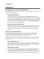
1
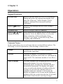
ENERGY AND COMFORT
Ventilation Testing
VELOCICALC®
Air Velocity Meter
Models 9535/9535-A
Operation and Service Manual
Copyright©
TSI Incorporated / May 2007 / All rights reserved.
Address
TSI Incorporated / 500 Cardigan Road / Shoreview, MN 55126 / USA
Fax No.
(651) 490-3824
LIMITATION OF WARRANTY AND LIABILITY (effective July 2000)
Seller warrants the goods sold hereunder, under normal use and service as described in the
operator's manual, shall be free from defects in workmanship and material for twenty-four (24)
months, or the length of time specified in the operator's manual, from the date of shipment to the
customer. This warranty period is inclusive of any statutory warranty. This limited warranty is
subject to the following exclusions:
a.
Hot-wire or hot-film sensors used with research anemometers, and certain other
components when indicated in specifications, are warranted for 90 days from the date of
shipment.
b.
Parts repaired or replaced as a result of repair services are warranted to be free from
defects in workmanship and material, under normal use, for 90 days from the date of
shipment.
c.
Seller does not provide any warranty on finished goods manufactured by others or on any
fuses, batteries or other consumable materials. Only the original manufacturer's warranty
applies.
d.
Unless specifically authorized in a separate writing by Seller, Seller makes no warranty
with respect to, and shall have no liability in connection with, goods which are
incorporated into other products or equipment, or which are modified by any person other
than Seller.
The foregoing is IN LIEU OF all other warranties and is subject to the LIMITATIONS stated
herein. NO OTHER EXPRESS OR IMPLIED WARRANTY OF FITNESS FOR
PARTICULAR PURPOSE OR MERCHANTABILITY IS MADE.
TO THE EXTENT PERMITTED BY LAW, THE EXCLUSIVE REMEDY OF THE USER OR
BUYER, AND THE LIMIT OF SELLER'S LIABILITY FOR ANY AND ALL LOSSES,
INJURIES, OR DAMAGES CONCERNING THE GOODS (INCLUDING CLAIMS BASED
ON CONTRACT, NEGLIGENCE, TORT, STRICT LIABILITY OR OTHERWISE) SHALL
BE THE RETURN OF GOODS TO SELLER AND THE REFUND OF THE PURCHASE
PRICE, OR, AT THE OPTION OF SELLER, THE REPAIR OR REPLACEMENT OF THE
GOODS. IN NO EVENT SHALL SELLER BE LIABLE FOR ANY SPECIAL,
CONSEQUENTIAL OR INCIDENTAL DAMAGES. SELLER SHALL NOT BE
RESPONSIBLE FOR INSTALLATION, DISMANTLING OR REINSTALLATION COSTS
OR CHARGES. No Action, regardless of form, may be brought against Seller more than 12
months after a cause of action has accrued. The goods returned under warranty to Seller's
factory shall be at Buyer's risk of loss, and will be returned, if at all, at Seller's risk of loss.
Buyer and all users are deemed to have accepted this LIMITATION OF WARRANTY AND
LIABILITY, which contains the complete and exclusive limited warranty of Seller. This
LIMITATION OF WARRANTY AND LIABILITY may not be amended, modified or its terms
waived, except by writing signed by an Officer of Seller.
Service Policy
Knowing that inoperative or defective instruments are as detrimental to TSI as they are to our
customers, our service policy is designed to give prompt attention to any problems. If any
malfunction is discovered, please contact your nearest sales office or representative, or call
Customer Service department at (800) 874-2811 (USA) or (1) 651-490-2811 (International).
CONTENTS
CHAPTER 1 UNPACKING AND PARTS IDENTIFICATION ............ 1
CHAPTER 2 SETTING-UP................................................................. 3
Supplying Power to the Model 9535/9535-A .................................. 3
Installing the Batteries ...............................................................3
Using the Optional AC Adapter ................................................. 3
Using the Telescoping Probe ......................................................... 3
Extending the Probe ..................................................................3
Retracting the Probe.................................................................. 3
Connecting to a Computer..............................................................4
CHAPTER 3 OPERATION ................................................................. 5
Keypad Functions ...........................................................................5
Common Terms ..............................................................................5
Menus .............................................................................................6
DISPLAY SETUP.................................................................................6
SETTINGS .........................................................................................6
FLOW SET UP....................................................................................6
ACTUAL/STANDARD SETUP ................................................................ 6
DATA LOGGING .................................................................................7
Measurements...........................................................................7
Log Mode/Log Settings .............................................................7
Delete Data................................................................................7
% Memory .................................................................................7
APPLICATIONS ..................................................................................7
LogDat2™ Downloading Software ................................................. 7
CHAPTER 4 MAINTENANCE............................................................ 9
Recalibration...................................................................................9
Cases..............................................................................................9
Storage ...........................................................................................9
CHAPTER 5 TROUBLESHOOTING................................................11
APPENDIX A SPECIFICATIONS.....................................................13
iii
Chapter 1
Unpacking and Parts Identification
Carefully unpack the instrument and accessories from the shipping
container. Check the individual parts against the list of components. If
anything is missing or damaged, notify TSI immediately.
1. Carrying case
2. Instrument
3. USB cable
4. CD-ROM with downloading software
1
Chapter 2
Setting-up
Supplying Power to the Model 9535/9535-A
The TSI Model 9535/9535-A VELOCICALC Air Velocity Meter is powered
with four size AA batteries.
Installing the Batteries
Insert four AA batteries as indicated by the diagram located on the
inside of the battery compartment. The Model 9535/9535-A is designed
to operate with either alkaline or NiMH rechargeable batteries, although
it will not recharge NiMH batteries. Battery life will be shorter if NiMH
batteries are used. Carbon-zinc batteries are not recommended because
of the danger of battery acid leakage.
Using the Optional AC Adapter
When using the AC adapter, the batteries (if installed) will be bypassed.
Be sure to provide the correct voltage and frequency, which is marked
on the back of the AC adapter. The AC adapter will not recharge the
batteries.
Using the Telescoping Probe
The telescoping probe contains the velocity, temperature, and humidity
sensors. When using the probe, make sure the sensor window is fully
exposed and the orientation dimple is facing upstream.
NOTE: For temperature measurements, make sure that at least 3 inches
(7.5 cm) of the probe is in the flow to allow the temperature sensor to be in
the air stream.
Extending the Probe
To extend the probe, hold the handle in one hand while pulling on the
probe tip with the other hand. Do not hold the cable while extending the
probe as this prevents the probe from extending.
Retracting the Probe
To retract the probe, hold the handle in one hand while gently pushing
on the probe tip with the other hand. If you feel the probe antenna
binding, pull gently on the probe cable until the smallest antenna section
is retracted. Collapse the rest of the antenna by pressing the probe tip.
3
Connecting to a Computer
Use the Computer Interface USB Cable provided with the Model
9535/9535-A to connect the instrument to a computer for downloading
stored data or for remote polling. Connect the end labeled “COMPUTER” to
the computer USB port and the other end to the data port of the Model
9535/9535-A.
For more information on how to download stored data see Chapter 3 section
titled LogDat2™ Downloading Software.
Caution: This symbol is used to indicate that the data port
of the Model 9535/9535-A is not intended for connection
to a public telecommunications network. Connect the USB
data port only to another USB port.
4
Chapter 2
Chapter 3
Operation
Keypad Functions
ON/OFF Key
Press to turn the Model 9535/9535-A on and off.
During the power up sequence the display will
show the following: Model Number, Serial
Number, Software Revision and Last Date
Calibrated.
Arrow (ST) Keys
Press to scroll through choices while setting a
parameter.
(Enter) Key
Press to accept a value or condition.
Arrow (gor h) and
Menu Soft Keys
Press arrow keys to change choices while setting a
parameter. Press the Menu soft key to select the
Menu selections, which are Display Setup,
Settings, Flow Setup, Actual/Std Set up, Data
Logging, and Calibration.
Common Terms
In this manual there are several terms that are used in different places. The
following is a brief explanation of the meanings of those terms.
Sample
Consists of all of the measurement parameters
stored at the same time.
Test ID
A group of samples. The statistics (average,
minimum, maximum, and count) are calculated for
each test ID. The maximum number of test IDs is
100.
Time Constant
The time constant is an averaging period. It is used to
dampen the display. If you are experiencing
fluctuating flows, a longer time constant will slow
down those fluctuations. The display will update
every second, but the displayed reading will be the
average over the last time constant period. For
example, if the time constant is 10 seconds, the
display will update every second, but the displayed
reading will be the average from the last 10 seconds.
This is also referred to as a “moving average”.
5
Menus
DISPLAY SETUP
Display setup menu is where you will setup the desired parameters to be
displayed on the running screen. With a parameter highlighted you can then
use the ON soft key to have it show up on the running screen or select the
OFF soft key to turn off the parameter. Use PRIMARY soft key to have a
parameter show up on the running screen in a larger display. Only one
parameter can be selected as a primary, and up to 2 secondary parameters
can be selected at one time.
SETTINGS
Settings menu is where you can set the general settings. These include
Language, Beeper, Select Units, Time Constant, Contrast, Set Time, Set
Date, Time Format, Date Format, Number Format, Backlight and Auto Off.
Use the g or h soft keys to adjust the settings for each option and use the key to accept settings.
FLOW SET UP
In Flow Setup mode, there are 5 types: Round Duct, Rectangle Duct, Duct
Area, Horn and Pressure Units. Use the g or h soft keys to scroll through
the types and then press the key to accept the desired type. To change the
value, highlight the Enter Settings option and press the key. Use the
instructions below to change the value of the type that you selected.
NOTE: The horn numbers are the models of the horns. For example, 100
refers to a horn model number AM 100. Only horns with Model numbers as
follows can be used with this function: AM 100, AM 300, AM 600, and
AM 1200. If a horn model number is chosen, the instrument will return to
measuring mode and use a preprogrammed curve to calculate flow rate
from velocity.
ACTUAL/STANDARD SETUP
Choose Actual/Standard measurements and parameters in the Act/Std Setup
menu. Within this menu, the user can also select Standard Temperature,
Standard Pressure and a source for the actual temperature. The actual
barometric pressure must be entered to convert air velocity and volume
measurements to actual conditions.
6
Chapter 3
DATA LOGGING
Measurements
Measurements to be logged are independent of measurements on the
display, and must therefore be selected under DATA LOGGING Æ
Measurements.
Log Mode/Log Settings
Manual mode does not automatically save data, but instead prompts the
user to save a sample.
Delete Data
Use this to delete all data, delete test or delete sample.
% Memory
This option displays the memory available. Delete All, under Delete
Data, will clear memory and reset the memory available.
APPLICATIONS
You can choose Draft and Turbulence in the Applications menu. After
choosing one of these applications, take measurements or enter data for each
line.
LogDat2™ Downloading Software
The TSI Model 9535/9535-A comes with special software called LogDat2
Downloading Software, which is designed to provide you with maximum
flexibility and power. To install this software on your computer, follow the
instructions on the label of the LogDat2 CD-ROM.
To download data from the Model 9535/9535-A, connect the supplied
computer interface USB cable to the Model 9535/9535-A and to a computer
USB port. Then run the LogDat2 software. Within the LogDat2 software,
either select the tests to be downloaded or double-click on a test to open it.
Operation
7
Chapter 4
Maintenance
The Model 9535/9535-A requires very little maintenance to keep it
performing well.
Recalibration
To maintain a high degree of accuracy in your measurements, we
recommend that you return your Model 9535/9535-A to TSI for annual
recalibration. Please contact one of TSI’s offices or your local distributor to
make service arrangements and to receive a Return Material Authorization
(RMA) number. To fill out an online RMA form, visit TSI’s website at
http://service.tsi.com.
U.S. & International
TSI Incorporated
500 Cardigan Road
Shoreview MN 55126-3996
Tel: (800) 874-2811
(651) 490-2811
Fax: (651) 490-3824
The Model 9535/9535-A can also be recalibrated in the field using the
CALIBRATION menu. These field adjustments are intended to make minor
changes in calibration to match a user's calibration standards. The field
adjustment is NOT intended as a complete calibration capability. For
complete, multiple-point calibration and certification, the instrument must be
returned to the factory.
Cases
If the instrument case or storage case needs cleaning, wipe it off with a soft
cloth and isopropyl alcohol or a mild detergent. Never immerse the Model
9535/9535-A. If the enclosure of the Model 9535/9535-A or the AC adapter
becomes broken, it must be replaced immediately to prevent access to
hazardous voltage.
Storage
Remove the batteries when storing the unit for more than one month to
prevent damage due to battery leakage.
9
Chapter 5
Troubleshooting
Table 5-1 lists the symptoms, possible causes, and recommended solutions
for common problems encountered with the Model 9535/9535-A. If your
symptom is not listed, or if none of the solutions solves your problem, please
contact TSI.
Table 5-1: Troubleshooting the Model 9535/9535-A
Symptom
No Display
Possible Causes
Unit not turned on
Low or dead batteries
Dirty battery contacts
Velocity reading
fluctuates unstable
Fluctuating flow
No response to
keypad
Keypad locked out
Instrument Error
message appears
Memory is full
Fault in instrument
Corrective Action
Switch unit on.
Replace batteries or plug
in AC adapter.
Clean the battery
contacts.
Reposition probe in
less-turbulent flow or use
longer time constant.
Unlock keypad by
pressing ST keys
simultaneously.
Download data if desired,
then DELETE ALL
memory.
Factory service required
on instrument.
WARNING!
Remove the probe from excessive temperature immediately:
excessive heat can damage the sensor. Operating temperature limits
can be found in Appendix A, Specifications.
11
Appendix A
Specifications
Specifications are subject to change without notice.
Velocity:
Range:
Accuracy1&2:
Resolution:
Duct Size:
Range:
0 to 6000 ft/min (0 to 30 m/s)
±3% of reading or ±3 ft/min (±0.015 m/s), whichever is
greater
1 ft/min (0.01 m/s)
1 to 250 inches in increments of 0.1 in. (1 to 635 cm in
increments of 0.1 cm)
Volumetric Flowrate:
Range:
Actual range is a function of actual velocity, pressure, duct
size, and K factor
Temperature:
Range:
Accuracy3:
Resolution:
0 to 200°F (-18 to 93°C)
±0.5°F (±0.3°C)
0.1°F (0.1°C)
Instrument Temperature Range:
Operating (Electronics): 40 to 113°F (5 to 45°C)
Operating (Probe):
0 to 200°F (-18 to 93°C)
Storage:
-4 to 140°F (-20 to 60°C)
Instrument Operating Conditions:
Altitude up to 4000 meters
Relative humidity up to 80% RH, non-condensing
Pollution degree 1 in accordance with IEC 664
Transient over voltage category II
Data Storage Capabilities:
Range:
12,700+ samples and 100 test IDs (one sample can contain
fourteen measurement types)
Time Constant:
User-selectable
Response Time:
Velocity:
200 msec
Temperature:
2 minutes (to 66% of final value)
External Meter Dimensions:
3.3 in. × 7.0 in. × 1.8 in. (8.4 cm × 17.8 cm × 4.4 cm)
13
Meter Probe Dimensions:
Probe length:
40 in. (101.6 cm)
Probe diameter of tip:
0.28 in. (7.0 mm)
Probe diameter of base: 0.51 in. (13.0 mm)
Articulating Probe Dimensions:
Articulating section length:
7.8 in. (19.7 cm)
Diameter of articulating knuckle: 0.38 in. (9.5 mm)
Meter Weight:
Weight with batteries:
0.6 lbs (0.27 kg)
Power Requirements:
Four AA-size batteries (included) or AC adapter (optional) 9 VDC, 300 mA,
4-18 watts (input voltage and frequency vary depending on which adapter is
used)
1
2
3
14
Temperature compensated over an air temperature range of 40 to 150°F (5 to 65°C).
The accuracy statement of ±3.0% of reading or ±3 ft/min (±0.015 m/s), whichever is greater,
begins at 30 ft/min through 6000 ft/min (0.15 m/s through 30 m/s).
Accuracy with instrument case at 77°F (25°C), add uncertainty of 0.05°F/°F (0.03°C/°C) for
change in instrument temperature.
Appendix A
TSI Incorporated – 500 Cardigan Road, Shoreview, MN 55126 U.S.A
USA
Tel: +1 800 874 2811 E-mail: [email protected]
Website: www.tsi.com
UK
Tel: +44 149 4 459200 E-mail: [email protected]
Website: www.tsiinc.co.uk
France
Tel: +33 491 95 21 90 E-mail: [email protected] Website: www.tsiinc.fr
Germany Tel: +49 241 523030 E-mail: [email protected] Website: www.tsiinc.de
Sweden Tel: +46 8 595 13230 E-mail: [email protected]
Website: www.tsi.se
India
Tel: +91 80 41132470 E-mail: [email protected]
China
Tel: +86 10 8260 1595 E-mail: [email protected]
Contact your local TSI Distributor or visit our website www.tsi.com for more detailed specifications.
P/N 1980563 Rev B
Copyright © 2007 by TSI Incorporated
Printed in U.S.A.