Download 4 - Free

Transcript
TECHNICAL
ANNUAL
1998
Grundig Service
Hotline Germany...
...Mo-Fr 8.00-16.30 hr
Technical Support:
TV/SAT
VCR/LiveCam
HiFi/Audio
Car Audio
Telecommunication
0180/52318-41
0180/52318-42
0180/52318-43
0180/52318-44
0180/52318-45
Fax:
0180/52318-51
Spare Parts Order Desk:
Phone:
Fax:
0180/52318-40
0180/52318-50
Kundendienst Ost, Wittestraße 30 E , 13509 Berlin
Manager: Phone (0 30) 4 38 03-20, Fax (0 30) 4 32 55 97
Kundendienst Nord, Kolumbusstr. 14 , 22113 Hamburg
Manager: Phone (0 40) 7 33 31-218, -248, Fax (0 40) 7 33 31-333
Kundendienst West, Horbeller Str. 19, 50858 Köln
Manager: Phone (0 22 34) 95 81-280, -250, Fax (0 22 34) 95 81-278
Kundendienst Mitte, Dudenstr. 45 - 53, 68167 Mannheim
Manager: Phone (06 21) 33 76-210, -270, Fax (06 21) 33 76-251
Kundendienst Süd, Beuthener Str. 65, 90471 Nürnberg
Manager: Phone (09 11) 7 03-12 60, -12 69, Fax (09 11) 7 03-11 27
Subject to alteration!
This publication, or parts thereof, may not be reprinted without permission of the publisher.
Publisher:
GRUNDIG Service GmbH
Zentralkundendienst; Technische Dokumentation
We would be obliged for any tips and suggestions or criticism which we shall give our attention.
Please send to fax number: ++49 911 / 7 03 19 05
Technical
Annual 1998
Dear Readers,
In order not to go beyond the limits of a booklet this issues contains
as usual only the latest data and technical changes.
For informations frequently repeated in the past few years please
refer to the previous issues of the Grundig Technical Annual.
Contents:
General Part
1.1
Gen.
Part
TV Technology
2.1
TV
Video Technology
3.1
Video
Camcorder Technology
4.1
Camcorder
Video Editing Systems
5.1 Systems
Satellite Reception
6.1
SAT
Audio Technology
7.1
Audio
Electronic Appliances
8.1 Appliances
Editing
Electronic
Subject to alteration
Table of Contents
Partners help each other
Please help us find hidden faults and return all modules with a brief
description of the fault.
Fehleranhänger für Module / Label tag for modules
Cartellino dei diffeti per i moduli / Fiche suiveuse pour module
Etiqueta de avería bara módulos
Fehler tritt sofort auf / Fault aoccurs immediately / Il difetto compare subito
Le défaut apparaît immédiatement / La avería aparece inmediatamente
Fehler tritt nur zeitweise auf / Fault aoccurs intermittently / Il difetto compare solo
a periodi / Le défaut est intermittent / La avería aparece intermitentemente
Fehler tritt nach ca.
Fault occurs after approx
Il difetto compare dopo ca.
Le défaut apparaî aprés environ
La avería aparece tras
...........
...........
...........
...........
...........
Minuten aut
minutes
minuti
minutes de fonctionnement
minutos
Wackelkontakt / intermittent contact / Contatto difettoso
Mauvais contact intermittent / contacto intermitente
Sonstige Fehlererscheinungen: / Other faults: / Altri difetti:
Autres défauts: / Otras averías:
Bitte unterstützen Sie uns beim Auffinden versteckter Fehler: Versehen
Sie alle Modul-Rückläufer mit vollständig ausgefüllten Fehleranhängern!
Please help us to trace obscure faults: Ensure all modules are returned
with label tag completed!
Collaborate con noi nella ricera deidifetti:
corredate ogni modulo che rimandate indietro dei cartellino
dei diffetti compilato in tutti i suoi punti!
Afin de nous permettre d'améliorer la Qualité de notre service,
nous vous prions de nous renvoyer avec votre module, cette
étiquette dûment renseignée. Merci pour votre collaboration.
Ayúdennos a encontrar las averías ocultas: procuren que cada
módulo devuelto vaya con su etiqueta de avería para módulos
debidamente relienda!
Thank you very much for your kind assistance.
Sach-Nr.: 09624-645.03
FÜR IHR RÜCKABETEIL
FOR RETURNING FAULTY
MODULES
ALLEGARE AL PEZZO CHE
VIENE RIMANDATO INDIETRO
POUR RETOURRNER AVEC LE
MODULE DEFECTUEUX
PARA DEVOLUCIÓN DE
MÓDULOS AVERIADOS
For this purpose, a green fault tag or white adhesive label is enclosed
with all modules (insert cards) delivered by the GRUNDIG service
organisation.
Grundig Annual 1998
Table of Contents
General Part
Contents: General Part
Addresses:
Grundig
Grundig Service GmbH
Grundig Sales Companies (Europe)
Grundig Sales Companies (International)
Grundig Agencies (International)
1.2
1.2
1.3
1.5
1.6
GRUNDIG Professional Electronics GmbH
Product Range and Customer Services, Test and Measuring Instruments 1.10
Business Unit Test and Measuring Instruments
1.11
Service Training Courses for our Customers
1.15
General Information on Safety, MOS, Chip and Laser Technology
1.16
ISDN-Info Tip
1.24
Grundig Universal Remote Controls
1.28
Pinning of Sockets and Plugs
1.33
Grundig Service
1.1
Gen.
Part
General Part
Table of Contents
Grundig Annual 1998
GRUNDIG
General Management
Kurgartenstraße 37
90762 Fürth
Tel. (09 11) 7 03-0
Telefax: (09 11) 70 53 76
Btx: *32700#
Grundig Service GmbH
Zentralkundendienst
Beuthener Str. 55
90471 Nürnberg
Tel. (09 11) 7 03-0
Telefax: (09 11) 7 03-19 03
Kundendienst Ost
Wittestraße 30 E
13509 Berlin
Telefon (0 30) 4 38 03-20
Telefax (0 30) 4 32 55 97
Gen.
Part
Kundendienst Nord
Kolumbusstr. 14
22113 Hamburg
Telefon (0 40) 7 33 31-218/-248
Telefax (0 40) 7 33 31-333
Kundendienst West
Horbeller Str. 19
50858 Köln
Telefon (0 22 34) 95 81-2 80
Telefax (0 22 34) 95 81-2 78
Kundendienst Mitte
Dudenstr. 45 - 53
68167 Mannheim
Telefon (06 21) 33 76-210
Telefax (06 21) 33 76-251
Kundendienst Süd
Beuthener Str. 65
90471 Nürnberg
Telefon (09 11) 7 03-12 60
Telefax (09 11) 7 03-11 27
1.2
Grundig Service
Grundig Annual 1998
Table of Contents
General Part
Grundig Sales Companies (Europa)
S.A. Grundig Belux N. V.
Deltapark Unit 3, Weihoek 3 G, B-1930 Zaventem
Phone: (00 32-2) 7 16 04 00, Fax: (00 32-2) 7 16 03 80
Grundig Danmark A/S
Lejrvej 19, DK-3500 Vaerløse
Phone: (00 45) 44 48 68 22, Fax: (00 45) 44 48 62 63
Grundig Oy
Luoteisrinne 5, SF-02271 Espoo, Finland
Phone: (0 03 58) 98 04 39 00, Fax: (0 03 58) 98 04 39 01
Grundig France S. A.
5, Boulevard Marcel Pourtout, F-92563 Rueil Malmaison Cedex
Phone: (00 33-1) 41 39 26 26, Telex: 0 42-63 45 04, Fax: (00 33-1) 47 08 69 48
Grundig UK Limited.
Elstree Way, Borehamwood, Herts, WD6 1RX, Great Britain
Phone: (00 44-181) 324 94 00, Fax: (00 44-181) 324 94 0131.10.1997
Grundig Italiana S. P. A.
Via G. B. Trener 8, I-38100 Trento
Phone: (00 39-4 61) 89 31 11, Fax: (00 39-4 61) 89 34 08
Gen.
Part
Grundig Nederland B. V.
Joan Muyskenweg 22, NL-1096 CJ Amsterdam
Phone: (00 31-20) 5 68 15 68, Fax: (00 31-20) 5 68 14 06
Grundig Norge AS
Glynitveien 25, Postboks 234, N-1401 Ski
Phone: (00 47) 64 87 82 00, Fax: (00 47) 64 87 66 10
Grundig Austria Ges. m. b. H.
Breitenfurter Str. 43-45, A-1120 Wien
Phone:(00 43-1) 81 11 73 06, Telex 0 47-13 39 03, Fax: (00 43-1) 81 11 77 13
Grundig Portuguesa, Comércio de Artigos Electronicos Lda.
Rua Bento de Jesus Caraça, 17, P-1495 Cruz Quebrada
Phone: (0 03 51-1) 4 19 75 70, Fax: (0 03 51-1) 4 19 90 83
Grundig Svenska AB
Box 4050, Albygatan 109 D, S-171 04 Solna
Phone: (00 46-8) 6 29 85 30, Telex: 0 54-1 99 34, Fax: (00 46-8) 6 29 85 70
Grundig (Schweiz) AG
Steinackerstr. 28, CH-8302 Kloten
Phone: (00 41-1) 8 15 81 11, Fax: (00 41-1) 8 13 52 31
Grundig Service
1.3
General Part
Table of Contents
Grundig Annual 1998
Grundig Espana S. A.
Solsonés, 2, Edif. Muntadas (Mas Blau I), E-08820 El Prat de Llobregat (Barcelona)
Phone: (00 34-3) 4 79 92 00, Fax: (00 34-3) 4 79 92 47
Grundig Ireland Ltd.
2 Waverley Office Park, Old Naas Road, Dublin 12/Eire
Phone: (0 03 53-1) 4 50 97 17, Fax: (0 03 53-1) 4 50 99 36
Grundig Polska SP. Z.O.O. (After-Sales Service)
Ul. Czéstochowska 140, PL - 62-800 Kalisz, Poland
Phone: (00 48-62) 7 66 77 70, Fax: (00 48-62) 7 66 77 72
Grundig Polska SP. Z.O.O.
Ul. Raclawicka 146, PL - 02-117 Warszawa, Poland
Phone: (00 48-22) 6 68 62 66, Fax: (00 48-22) 6 68 62 54
Grundig spol. s r.o.
Koperniková 2, CZ - 12 000 Praha 2, Czechia
Phone: (0 04 20) 2 - 24 23 90 99, (0 04 20) 2 - 24 23 90 81, Fax: (0 04 20) 2 - 24 23 51 01
Grundig Slovensko spol. s r.o.
Mileticova 23, SK - 820 06 Bratislava, Slovakia
Phone: (0 04 21) 7 - 52 67 219, (0 04 21) 7 - 54 44 377, Fax: (0 04 21) 7 - 54 25 677
Gen.
Part
Grundig Magyarország Kft.
Bécsi út 85, H - 1036 Budapest, Hungary
Phone: (00 36) 1 - 25 08 142, (00 36) 1 - 25 08 143, Fax: (00 36) 1 - 25 08 144
Grundig Slovenija d.o.o.
Dunajska 22, SL - 1511 Ljubljana, Slovenia
Phone: (0 03 86) 61 - 32 88 79, (0 03 86) 61 - 32 88 83, Fax: (0 03 86) 61 - 32 86 86
Grundig Predstavnistvo za Hvratsku
Metalceva 5, HR - 10000 Zagreb, Croatia
Phone and Fax: (0 03 85) 1 - 39 17 78, (0 03 85) 1 - 39 34 06
1.4
Grundig Service
Grundig Annual 1998
Table of Contents
General Part
Grundig Sales Companies (International)
Grundig Electronics India Pvt. Ltd.
No. 37, Sterling Road
Nungambakkam
Madras - 600 034
India
Phone: (00 91-44) 8 23 38 82, Fax: (00 91-44) 8 23 38 81
Grundig International Russia
UL. Obrazszova 17
103055 Moscow
Russia
Phone: (0 07-0 95) 9 73 30 54, Fax: (0 07-0 95) 9 73 30 57
Grundig International Russia
Izmeilovsky Prospekt 9/2
198005 St. Petersburg
Russia
Phone: (0 07-8 12) 2 51 43 81, Fax: (0 07-8 12) 2 59 93 22
Grundig Gulf F.Z.E.
P.O. Box 61012
Jebel Ali / Dubai
United Arab Emirates
Phone: (00 97-14) 83 89 89, Fax (00 97-14) 83 87 98
Grundig Service
Gen.
Part
1.5
General Part
Table of Contents
Grundig Annual 1998
Grundig Agencies (International)
Australia
Algeria
Argentina
Bulgaria
Cyprus
Gen.
Part
Egypt
Greece
Hong Kong/
China
Iceland
Iran
1.6
SCE-Southern Cross
Electronics Pty. Ltd.
26-30 Kent Street
Bekmore NSW 2192
Sydney
Australia
E.I.P.EL
14, Rue Khaled Bellagaune (ex Lulli)
Alger 16000
Crown Mustang S.A.
Av. Eva Perón 7455/85
1439 Buenos Aires
Argentina
Euro TV SAT
Bul. Bukston BL 15/D/11
1618 Sofia
Bulgaria
Ideal Grafico Ltd.
14C Stassinos Ave.
P.O. Box 4809
Nicosia
Cyprus
International Electrical Products
1, EL Obour Bldg. Salah Salem
P.O. Box 217
Heliopolis
Cairo
Egypt
Elex S.A.
13th km National Road
14564 Kifissia
Athens
Greece
Great Wall Electronics Ltd.
16/F., Riley House
88 Lei Muk Road
Kwai Chung
Hongkong
Television Center Ltd.
Sidumula 2
128 Reykjavik
Iceland
Pars Electric MFG Co.
563 Azadi Ave.
Theran
Iran
Phone: 00 61-2-7 50 31 66
Fax:
00 61-2-7 59 66 21
Phone: 0 02 13-2-63 66 94
Fax:
0 02 13-2-61 00 97
Phone: 00 54-1-686-10 71
Fax:
00 54-1-686-45 51
Phone: 0 03 59-2-80 86 06
Fax:
0 03 59-2-80 87 89
Phone: 00 35-72-44 10 75
Fax:
00 35-72-45 51 59
Phone: 0 02 02-2 61 83 33
Fax:
0 02 02-2 61 99 13
Phone: 00 30-1-8 07-67 11
Fax:
00 30-1-8 07-67 04
Phone: 0 08 52-24 10 86 68
Fax:
0 08 52-24 21 12 87
Phone: 0 03 54-5-68 90 90
Fax:
0 03 54-5-68 03 90
Phone: 00 98-21-6 02 51 00
Fax:
00 98-21-6 02 50 95
Grundig Service
Grundig Annual 1998
Iran
Israel
Malaysia
Malta
Morocco
New Zealand
Romania
South Africa
South Korea
Grundig Service
Table of Contents
Pars Services Co.
9 km Karadj Road
P.O. Box 13445/146
Theran
Iran
Pira Ltd.
19, Hatzfira Street
P.O. Box 28085
Tel Aviv
Israel
Luxor Electric Corp. Sdn. Bhd.
Wisma Luxor, No. 5
II. Beratu 12/4
46200 Petaling Jaya
Malaysia
Jokate Group of Co.Ltd.
Jokate Buildings
P.O. Box 1
Msida, Malta
Umareq
43, Bld. Ibn. Tachfine
Casablanca
Morocco
Sound group Holding Ltd.
Unit B/3 Rothwell Ave.
Albany P.O. Box 33-791
Takapuna, Auckland
New Zealand
SSH Marketing GmbH
Buchenstraße 15
D-63526 Erlensee
Germany
for car audio products:
SSM
Unit 4 Stand 6, Fedlife Park
Tonetti Street
Midrand
South Africa
for consumer electronics products:
Specialised Communications (Pty) Ltd.
P.O. Box 41602
Craighall 2024
33th Avenue, Orchards
Johannesburg 2192
South Africa
Lee & Lee International Co. Ltd.
Rm 1325 Life Officetel
Yoido Dong 61-3
Youngdeungpo-Ku
Seoul
Republic of Korea
General Part
Phone: 00 98-21-6 02 56 07
Fax:
00 98-21-6 02 56 01
Phone: 0 09 72-3-6 87 62 30
Fax:
0 09 72-3-5 37 47 07
Phone: 0 06 03-7 50-29 99
Fax:
0 06 03-7 56-59 00
Phone: 0 03 56-22 10 12
Fax:
0 03 56-24 31 54
Phone: 0 02 12-2-30 15 42
Fax:
0 02 12-2-30 30 03
Phone: 00 64-9-4 15-66 80
Fax:
00 64-9-4 15-66 83
Gen.
Part
Phone: 00 49-61 83-9 11 32-0
Fax:
00 49-61 83-9 11 32-18
Phone: 00 27-11-3 15 33 15
Fax:
00 27-11-8 05-36 27
Phone: 00 27-11-7 28 10 53
Fax:
00 27-11-7 28 15 25
Phone: 00 82-2-7 83 42 25
Fax:
00 82-2-7 86 13 29
1.7
Table of Contents
General Part
Taiwan
Taiwan
Tunisia
Turkey
U.S.A. Reexp.
Gen.
Part
U.S.A.
Export
1.8
Tatung Co.-AV-plant
22, Chungshan North Road,
3rd Sec.
Taipai
Taiwan, 104 R.O.C.
GRE Trading
P.O. Box 26-1182
11F. No. 602, Tun Hua South
Taipai
Taiwan, R.O.C.
Telectronic S.A.
Zone Industrielle den Ben
Arous
B.P. 294
Ben Aurous 2013
Tunis
Tunesia
Mercansoy
Yildirim Mah.
Ali Fuat Basgil Cad. 43
Bayrampasa 34170
Istanbul
Turkey
Manhattan Electric Industries
140, 58th Street
Brooklyn Army Terminal
Unit 4-G, Box No. 38
Brooklyn, NY 11220
U.S.A.
Lextronix Inc.
3520 Haven Avenue, Unit L
Redwood City, CA 94063
U.S.A.
EKG Export Kontor
Michaelistraße 4
D-20418 Hamburg
Germany
Grundig Annual 1998
Phone: 00 88 62-5 94-26 91
Fax:
00 88 62-5 94-26 60
Phone: 0 08 86-2-7 55-43 85
Fax:
0 08 86-2-7 55-23 93
Phone: 0 02 16-1-38 01 55
Fax:
0 02 16-1-38 51 25
Phone: 00 90-212-649-32 96
Fax:
00 90-212-537-56 98
Phone: 0 01-7 18-5 67 05 00
Fax:
0 01-7 18-5 67 06 30
Phone: 0 01-4 15-3 61 16 11
Fax:
0 01-4 15-3 61 17 24
Phone: 00 49-40-36 30 55
Fax:
00 49-40-36 39 90
Grundig Service
Table of Contents
Grundig Annual 1998
General Part
Partners help each other
Please help us find hidden faults and return all car radios with a
brief description of the fault.
For this purpose, this adhesive label is enclosed with all car
radios delivered by the GRUNDIG service organisation.
SERVICE- Dokument
Kauf-/Tauschdaten
Purchase/Replacement Data
Fehlerhinweise für Autogeräte
Fault Report for Car Radios
Rundfunkteil/Radio Stage
Code
Gerätenummer/Serial Number
UKW gestört
FM defective
LMK gestört
L/M/SW defective
keine Funktion No Funktions
Nur bei Geräten ohne Rahmennummer
Händlerstempel/Dealer Stamp
Firmenstempel/Company Stamp
Speicherfehler
Memory Fault
Suchlauffehler
Station Search
Stereofehler
Stereo Fault
Tonfehler
Sound Fault
Verkehrsfunk
Traffic Radio
SCV-Regelung
SCV-Control
VIP-Betrieb
VIP-Mode
RDS Funktionen RDS-Functions
Cassettenteil
Cassette Stage
Cassette läuft nicht
No Cassette drive
Gen.
Part
Cassettenlauf
Cassette Drive
Cassettenauswurf
Cassette Eject
Reverse Betrieb
Reverse Mode
Wiedergabe-Fehler
Playback Fault
Kanalausfall
Loss of Channel
Unterschrift
Signature
Austauschtag
Date of Replacement
Datum/Date
Verkaufsdatum
Date of Sale
Tausch durch
Replaced by
(WKZ/NL)
Wann tritt der Fehler auf
When does the fault occur
Immer
Immediatly
Nur zeitweise
Intermittent
Nur bei Kälte
Only when Cold
Sonstige Fehler
Other of Faults
09624-843.90
Laufgeräusche
Mechanical Noise
Nur bei Wärme Only when Hot
Thank you very much for your kind assistance.
Grundig Service
1.9
Table of Contents
General Part
Grundig Annual 1998
Product Range and Customer Services
Test and Measuring Instruments
Gen.
Part
Oscilloscopes
MO 30 - 30MHz Dual Channel Oscilloscope
MO 32 - 30MHz Dual Channel Oscilloscope
Laboratory and Service
Measuring Instruments
RLC 300, RLC 200 and RLC 100 - Automatic Programmable R-L-C Meter
PN 300 and PN 200 - Programmable Power Supply
UZ 2500 - Universal Counter (2.4GHz) with A-, B- and C-channel
UZ 2400 - Universal Counter (2.4GHz) with A- and C-channel
RF 1000 - RF Millivoltmeter
MV 100 - RF Millivoltmeter
DM 100 - Digital Multimeter
TG 100 - Sine Wave Generator
FG 100 - Function Generator
Video Measuring
Instruments
FG 9 S/PLL - Colour Generator
FG 70 S/PLL/VPS/NICAM - Colour Generator
VG 1100 PAL/NTSC - Video Generator
VTG 700 sat - Video Transmission Generator
PALplus Equipment
PPE400 - Professional PALplus Studio Encoder
PPE600 - Professional PALplus Studio Decoder
VTG 700 PALplus - Video Transmission Generator
Antenna Measuring
Instruments
ME 400 (Printer) - Antenna Measuring Receiver
ME 900 - Antenna Measuring Receiver
ME 100 - Combination Measuring Receiver
ME 700 SAT - Combination Measuring Receiver
ME 900 SAT - Combination Measuring Receiver
ME 900 color - Combination Measuring Receiver
SM 200 (Polarizer) - Satellite Measuring Receiver
Accessories
Connecting cables, probes and adapters,
oscilloscope accessories
For deliverability and advertising literature please contact:
Grundig Instruments
Test- und Meßsysteme GmbH
Würzburger Str. 150, D-90766 Fürth
Phone: 0911 / 703-4118
Fax: 0911 / 703-4130
1.10
Grundig Service
Grundig Annual 1998
Table of Contents
General Part
Test and Measuring Instruments (Germany)
Area Manager North
Area Manager West
Area Manager Centre
Area Manager South
Sales Area Northeast
Göpel electronic GmbH
H. Siebrasse
Hagenkamp 15
D-30982 Pattensen
K. Vogel
Walter-Freitag-Str. 19
D-42899 Remscheid
K.-H. Kaiser
Am Klingelborn 29
D-60437 Frankfurt
W. Meinicke
Behringstraße 46
D-90542 Eckental
Dipl.-Ing. Andre Schrank
Straße 142, Nr. 33
D-13053 Berlin
Göschwitzer Straße 58/60
D-07745 Jena
Phone
Fax
0 50 66/20 31
0 50 66/20 32
Phone
Fax
0 21 91/94 86-70
0 21 91/94 86-69
Phone
Fax
0 61 01/4 89 43
0 61 01/4 88 36
Phone
Fax
0 91 26/28 80 83
0 91 26/28 80 96
Phone
Fax
030/9 82 42 42
030/9 82 42 41
Phone
Fax
0 36 41/68 96-66
0 36 41/68 96-44
Phone
Fax
+61-2-97 48 01 55
+61-2-97 48 18 36
Phone
Fax
+43-1-8 11 17-0
+43-1-8 11 17-599
Phone
Fax
+32-27 16 04 00
+32-27 16 03 80
Phone
Fax
+45-75 56 70 00
+45-75 56 70 07
Phone
Fax
+45-36 72 20 00
+45-36 72 04 40
Phone
Fax
+45-32-88 57 13
+45-43 43 23 90
Phone
Fax
+20-2-3 49 09 22
+20-2-3 49 21 42
Phone
Fax
+358-19-8 71 11
+358-19-8 71 15 00
Phone
Fax
+33-1-69 20 40 10
+33-1-69 20 36 04
Phone
Fax
+30-341-7 21 72
+30-341-7 21 72
Phone
Fax
+852-5-8 33 02 22
+852-5-8 27 56 56
Test and Measuring Instruments (International)
Australia
Austria
Belgium
Denmark
Denmark
Denmark
Egypt
Finland
France
Greece
Hong Kong
Grundig Service
Rohde & Schwarz Pty. Ltd.
63 Parramatta Road
Silverwater N.S.W. 21 41
GRUNDIG Austria Ges.m.b.H.
Breitenfurter Straße 45-47
A-1120 Wien
GRUNDIG Belux N.V./S.A.
Deltapark, Weihoek 3 - Unit 3
1930 Zaventem
Erik Blichfeld A/S
Essen 27
DK-6000 Kolding
Witronic A/S
Roskildevej 308
DK-2610 Rødovre
Philips TV Test Equipment AS
Kornmarksvey 21
2605 Brøndby
Philips Egypt
10, Abdel Rahman El Rafei St.
Mohandessin
P.O.Box 242 Dokki
Cairo
Perel Oy
Torpankatu 28
SF-05800 Hyvinkää
Salies S.A.
65-67, Avenue Jean Jaurès
F-91122 Palaiseau
Berger Electronics
Industrial Area
61100 Kilhis
Schmidt & Co. (HK) Ltd.
18th Floor, Great Eagle Centre
23, Harbour Road
Wanchai
Gen.
Part
1.11
General Part
Hong Kong
India
Indonesia
Israel
Italy
Japan
Japan
Gen.
Part
South Korea
Netherlands
Norway
Portugal
Singapore
South Africa
1.12
Table of Contents
GEC Hong Kong
CCWu Building
302-308 Hennessy Road,
Wanchai
P.O.Box 15 GPO
Photophone Ltd.
Comel Division 179/5,
II Cross Road
Palace Lower Orchards
Bangalore - 560003
GAE PT Guna Elektro
Jl. Terusan Arjuna 50
RI-Jakarta Barat 11510
Kanion
8 Mikhaelis St.
Kiryat-Arie
P.O.Box 3783 Petah-Tikva
GRUNDIG Italiana S.p.A.
Via Brennero 364
I-38100 Trento
Matsushita Electric
Industrial Ltd.
Corporate International
Trade Division
(CID) Tokyo Office
Trade Center, P.O. Box 18
Tokyo, 105
Matsushita Electric
Industrial Co. Ltd. (MEI)
Corporate International
1-30 Shibadaimon 1-chome
Minato-Ku
Tokyo, 105
Seo Han Industries Co.
RM 803 Millionaire Bldg. 99-1
Garak-Dong, Songpa-Ku
Seoul
Korea
Koning en Hartman
Energieweg 1
P.O.Box 125
NL-2600 Delft
GRUNDIG Norge A/S
Postboks 234
N-1401 Ski
GRUNDIG Portuguesa
Rua Bento de Jesus
Caraca 17, Cruz Quebrada
1495 Lisboa
Gold Lite Pte. Ltd.
Attn. Mr. Lau
Henderson Industrial Park
#08-03
Singapore 159552
S.A. Philips (Pty) Ltd.
192-195 Main Road
Martindale 2092
Republic of South Africa
Grundig Annual 1998
Phone
Fax
+852-29 19 82 82
+852-28 34 57 73
Phone
Fax
+91-22-5 78 36 60
+91-22-5 78 43 25
Phone
Fax
+62-21-5 65 50 10
+62-21-5 65 50 30
Phone
Fax
+972-3-9 21 27 40
+972-3-8 22 07 51
Phone
Fax
+39-461-82 20 55
+39-461-89 32 07
Phone
Fax
+81-3-54 04 88 43
+81-3-54 04 88 49
Phone
Fax
+81-3-35 78 94 35
+81-3-34 59 66 14
Phone
Fax
+82- 2- 40 63 89 14
+82- 2- 40 63 89 5
Phone
Fax
+31-15-2 60 99 06
+31-15-2 61 91 94
Phone
Fax
+47-64-87 82 00
+47-64-87 66 10
Phone
Fax
+351- 141- 9 75 70
+351- 141- 9 90 83
Phone
Fax
+65-2 73 04 87
+65-2 73 50 06
Phone
Fax
+27-11-4 70 52 05
+27-11-4 70 52 06
Grundig Service
Grundig Annual 1998
Sweden
Sweden
Switzerland
Switzerland
Taiwan
Thailand
Czech Republic
UK
Table of Contents
Ferner Electronics AB
Phone
Veddestavägen 15
Fax
S-17526 Järfälla
Polystar AB
Phone
Dalhemsvägen 23
Fax
S-14146 Huddinge
GRUNDIG Schweiz AG
Phone
Steinackerstraße 28
Fax
CH-8302 Kloten
Erivision AG
Phone
Im Moos 13
Fax
CH-4710 Balsthal
Precision International Corp.
Phone
P.O. Box 03-15
Fax
Sanchung City
241 Taipei
Schmidt Scientific (Thailand) Ltd. Phone
69/5 Soi Sueksavittaya
Fax
North Sathorn Road
Bangkok 10500
Utes Brno
Phone
Purkynova 99 E
Fax
61245 Brno
GRUNDIG International Ltd.
Phone
Mill Road
Fax
GB-Rugby, Wanwickshire CV21 1PR
General Part
+46-8-7 60 83 60
+46-8-7 60 83 41
+46-8-7 11 57 39
+46-8-7 11 44 45
+41-1-8 15 81 11
+41-1-8 13 52 31
+41-62-3 91 11 34
+41-62-3 91 48 19
+886-2-9 99 08 50
+886-2-9 99 15 22
+662-2 36 77 84 86
+662-2 37 26 27
+420- 5- 41 12 28 35
+420- 5- 41 21 22 51
+44-17 88-54 58 21
+44-17 88-54 58 88
Subgroup Automotive Test and Measuring Instruments
Brazil
Norway
Portugal
Spain
Switzerland
Grundig Service
Nahuel Industrial Comercial Ltda
Rua Pedro Alexandrino 205
CEP 09901
Jordim Portinari, Diadema
Sao Paulo
a.s. Fartskriver
Persveien 32
P.B. 78, Oekern
0508 Oslo
Gruber Lda
Rua Oliveira Martins, 10-5°D
2810 Feijó
EDAGYAM S.L.
C/Rosalia de Castro, 40 bajo
15895 Milladoiro
(Santiago de Compostela)
W. Luginbühl AG
Bruneggerstraße 45
CH-5103 Möriken
Gen.
Part
Phone
Fax
+55-11-7 46 71 33
+55-11-7 46 71 81
Phone
Fax
+47-22-64 58 60
+47-22-65 83 50
Phone
Fax
+351-1-2 74 76 79
+351-1-2 59 23 47
Phone
Fax
+34-81-52 40 75
+34-81-52 40 75
Phone
Fax
+41-62-8 93 24 24
+41-62-8 93 37 05
1.13
Table of Contents
General Part
Grundig Annual 1998
Partners help each other
Please help us find hidden faults and return all modules with a brief
description of the fault.
Gen.
Part
Fehleranhänger für Module / Label tag for modules
Cartellino dei diffeti per i moduli / Fiche suiveuse pour module
Etiqueta de avería bara módulos
Fehler tritt sofort auf / Fault aoccurs immediately / Il difetto compare subito
Le défaut apparaît immédiatement / La avería aparece inmediatamente
Fehler tritt nur zeitweise auf / Fault aoccurs intermittently / Il difetto compare solo
a periodi / Le défaut est intermittent / La avería aparece intermitentemente
Fehler tritt nach ca.
Fault occurs after approx
Il difetto compare dopo ca.
Le défaut apparaî aprés environ
La avería aparece tras
...........
...........
...........
...........
...........
Minuten aut
minutes
minuti
minutes de fonctionnement
minutos
Wackelkontakt / intermittent contact / Contatto difettoso
Mauvais contact intermittent / contacto intermitente
Sonstige Fehlererscheinungen: / Other faults: / Altri difetti:
Autres défauts: / Otras averías:
Bitte unterstützen Sie uns beim Auffinden versteckter Fehler: Versehen
Sie alle Modul-Rückläufer mit vollständig ausgefüllten Fehleranhängern!
Please help us to trace obscure faults: Ensure all modules are returned
with label tag completed!
Collaborate con noi nella ricera deidifetti:
corredate ogni modulo che rimandate indietro dei cartellino
dei diffetti compilato in tutti i suoi punti!
Afin de nous permettre d'améliorer la Qualité de notre service,
nous vous prions de nous renvoyer avec votre module, cette
étiquette dûment renseignée. Merci pour votre collaboration.
Ayúdennos a encontrar las averías ocultas: procuren que cada
módulo devuelto vaya con su etiqueta de avería para módulos
debidamente relienda!
Sach-Nr.: 09624-645.03
FÜR IHR RÜCKABETEIL
FOR RETURNING FAULTY
MODULES
ALLEGARE AL PEZZO CHE
VIENE RIMANDATO INDIETRO
POUR RETOURRNER AVEC LE
MODULE DEFECTUEUX
PARA DEVOLUCIÓN DE
MÓDULOS AVERIADOS
For this purpose, a green fault tag or white adhesive label is enclosed
with all modules (insert cards) delivered by the GRUNDIG service
organisation.
Thank you very much for your kind assistance.
1.14
Grundig Service
Grundig Annual 1998
Table of Contents
General Part
SERVICE TRAINING COURSES for our Customers
We train you in intensive courses in the GRUNDIG after-sales service division in Nürnberg
as well as in one-day regional training courses.
We deal with all current questions on product technology in the fields of television, satellite
reception, video, digital audio, and communications.
For detailed information on these courses please see the technical training booklet which is
available on request from your competent GRUNDIG contact partner.
________________________________________________________________________
Training with Training Film Cassettes
GRUNDIG offers a training film titled “Servicing made easy - Training by Video” designed for private study
and practical application in the field of servicing which has proven very well. The present offer of video
cassettes comprises:
Training Film: Video VHS (2 x 4/1600)
Part No.:72007-744.60
Flow converter power supply • sequence and motor control • servo control/ATF • video signal path •
chroma signal path • mechanical adjustments • length ca. 90 minutes.
Training Film: Video VHS (VS 200/220)
Part No.:72007-744.70
Diagnosis • power supply • sequence and motor control • servo control • video and chroma signal path •
mechanical adjustments • length ca. 110 minutes.
Training Film: Television Compact Universal Chassis
Part No.:72007-744.80
Switched mode power supply• transistor line output stages 90/110 degrees • east/west modulator • multiGen.
standard reception • viewdata retrofitting • length ca. 55 minutes.
Part
Training Film: Video VHS (VS 310, 320, 380 HiFi)
Part No.:72007-744.90
(in English) 72007-744.91
(in Italian) 72007-744.92
Diagnosis • service works on drive mechanism• adjustments and mechanical settings • repair hints •
functional characteristics of electrical modules • length ca.110 minutes.
Training Film: The Horizontal TV Chassis
Part No.:72007-744.95
Line power supply • multi-standard reception • transistor line output stages 90/110 dregrees • viewdata and
PC connecting instructions • satellite receiver • satellite reception • adjustment of the paraboloidal reflector
• service hints • length ca. 60 minutes.
Training Film: Video VHS (VS 340/400)
Circuitry and mechanics • length ca. 90 minutes.
Part No.:72007-744.97
Training Film: Video VS 540 HiFi
Circuitry and mechanics • length ca. 80 minutes.
Part No.:72007-744.98
Training Film: STP 300 Satellite System
Installation of the satellite system STP 300 • length ca. 30 minutes.
Part No.:72007-744.61
Training Film: Highspeed Video Drive Mechanism HSD
Part No.:72007-744.81
Dismantling and re-assembling the drive mechanism • replacement of wearing parts • replacement of the
headwheel and the CTL head • adjustment of the tape run, tracking position and head gap position
indicator • length ca. 30 minutes.
Grundig Service
1.15
General Part
©
Table of Contents
Grundig Annual 1998
General Instructions for Safety, MOS, Chip and Laser Technology
© ü ç
This Service Manual covers the safety regulations which must be observed
when carrying out repairs.
It is to be regarded as a supplement to all Service Manuals which will be
issued in future without these safety regulations.
Preserve this Service Manual carefully and observe the instructions given
in it for product liability.
Please observe also all additional national safety regulations!
Contents
Page
Gen.
Part
Safety Instructions .......................................................................................... 1.17
Safety Standard Compliance ......................................................................... 1.17
Electrical Safety after Repairs ........................................................................ 1.18
Important Advice and Safety Tests relevant to Service Repairs ..................... 1.19
Important Safety Instructions ......................................................................... 1.19
Laser Safety ................................................................................................... 1.21
Safety Advice for Lithium Batteries ................................................................ 1.22
Handling of MOS Chip Components .............................................................. 1.22
MOS Soldering Instructions ........................................................................... 1.22
CHIP Technology ........................................................................................... 1.23
1.16
Grundig Service
Grundig Annual 1998
Table of Contents
General Part
Safety Instructions
The products identified in Service Manuals were manufactured to meet strict Quality and Safety Standards. It is
imperative that the Safety Standards are observed when carrying out repairs to ensure that the product always
conforms to IEC 65 or VDE Regulations and the harmonised National Safety Regulations, eg. Low Voltage Directive
(73/23/EEC), the Low Voltage Electrical Equipment (Safety) Regulations, 1989 (UK) and the Electricity at Work
Regulations, 1989 (UK) before it is returned to the owner.
This symbol:
!
is used to identify components which conform to IEC or VDE Guidelines! When these require replacement, for
continued compliance and protection, use only the original components specified in the Service Manual (List of Spare
Parts). For continued protection against the risk of fire, the type and rating of fuses (nominal value, characteristic
and rupturing rating) used as replacements must be as specified by the Standards!
After any repair, it is imperative that the Leakage Current and/or Insulation Resistance is checked as described in
this Safety Manual. If the result of the check indicates that the product does not conform, the user / owner must be
notified in writing. If the user / owner requests that the product is to be returned in a defective condition, the written
warning must draw notice to the risks.
In all cases:
– The mains plug and the fuse fitted (UK) must be checked and any defect found corrected.
– The mains lead, and any other connecting leads, must be checked for damage and defects rectified.
Check the insulation!
– The functional reliability of all tension relief and bending protection bushes provided in the product must be
checked and defects rectified.
– For continued safety compliance, safety determining parts in the product must not be damaged or evidently
unsuitable. This is especially valid for insulators and insulating parts.
– Use specified parts only. For components and assemblies marked with the Safety Symbol
specified spare parts only are strictly to be used.
!
the original
– Use, if applicable, only information published in Grundig Technical Bulletins or in the Grundig Infotip System.
– Thermally loaded solder pads and those passing large currents, known by experience to cause a risk, must be
thoroughly cleaned and re-soldered.
– Ensure that the ventilation openings are not obstructed or contaminated with dust.
– Ensure the proper disposal of exhausted batteries and accumulators (hazardous waste - environmental
protection!)
– For all receivers, ensure that the aerial system conforms to BSI CP 6330:1983 (UK).
– Maintain records of all checks, remedial action and disposals.
Safety Standard Compliance
After repairing a product which originally conformed to the Safety Class II (double insulated), the Insulation
Resistance and / or Leakage Current with the product switched on must be checked to VDE 0701 or to the National
Safety Regulations quoted above.
The products covered by these Instructions conform to the Safety Class II, as identified by the symbol:
Warning: After repairs are carried out to parts within this product, the Safety Instructions given in VDE 0701
(Repair Instructions) and / or VDE 0860 / IEC 65 / EN 60065 (Product Specification) must be
observed.
!
MOS
Components conforming to IEC or VDE Approval Specification! For replacement purposes, use parts with
the same specification only!
Observe the requirements when handling MOS Components!
Grundig Service
1.17
Gen.
Part
Table of Contents
General Part
Grundig Annual 1998
Electrical Safety after repairs
According to the Product Liability Laws, the Manufacturer is responsible for ensuring that the product presents no
danger to the user when used correctly. This risk is especially important with products which are operated from the
mains voltage supply. To ensure that safety parameters are maintained especially after repairs have been carried
out, it is imperative that the product is tested as specified in a recognised Test Procedure.
1. Products conforming to Safety Class I (earthed, Symbol
)
Earth lead Test.
Check that the earth lead performs its function by using a Continuity Tester. For this integrity of the connection
(conduction of current) from the protection lead contact in the plug to all metal parts that can be touched, with the
product switched on and with it switched off, must be proved. A maximum of 0.3Ω is permitted for the resistance of
a connecting lead with a length of up to 5 metres.
2. Products conforming to Safety Class II (insulated, Symbol
)
Insulating resistance measurements as specified in VDE 0701/Part 200.
The insulation resistance between all electrical functioning stages and metallic cabinet parts that can be touched
must be proved.
Measurement of the Insulation Resistance to VDE 0701
Connect an Insulation Test Meter (Utest = 500V DC) to both mains poles simultaneously and between the cabinet and
all other functional parts (aerial and connecting sockets, buttons, decorative trims, screws, etc.) made from metal
or metal alloy. The product is fault free if:
Risol > 2MΩ at Utest = 500V DC
Measuring time: > 1s
Note: The Insulation Resistance in some Safety Class II products can be < 2MΩ, depending upon
construction and the value of discharge resistors. In these cases, the Leakage Current is significant
and must be checked.
Gen.
Part
Measurement of the Leakage Current to VDE 0701
Connect a Leakage Current Meter (Utest = 220V AC*) to both mains poles simultaneously and between the cabinet
and all other functional parts (aerial and connecting sockets, buttons, decorative trims, screws, etc.) made from metal
or metal alloy. The product is fault free if:
Ileak < 1mA at Utest = 220V AC*
Measuring time: > 1s
* As, at the time of preparing these Safety Instructions, there is no British Standard Institute Standard that
is equivalent to VDE 0701, use a test voltage of 240V AC.
•
For testing to VDE 0701 / IEC 65 / BS 415 etc. we recommend that the measurements are carried out using the
PAC 500, PAT 1000, PAT 2000, Metratester 4/5 or suitable equipment. These can be obtained from:
e.g. Seaward Electronic Ltd
Bracken Hill, South West Ind Est
Peterlee
Co Durham
SR8 2JJ
Telephone: 0191-5863511
e.g. Gossen-Metrawatt GmbH
Thomas-Mann-Str. 16-20
D-90471 Nürnberg
Note: Models quoted may be superceded with new models with the passage of time.
•
The PAC provides an initial indication of a "pass" or "fail" and is also suitable for mobile (field service) use, and
the PAT units are designed for in-house use and for the maintenance of records and other professional uses and
are compatible with most PC systems.
•
If the safety of the product is not proven because:
– a repair and full restoration is not physically or economically possible
– or if the user / owner requests that repairs are not to be carried out,
the user / owner must be given a written warning of the risk!
•
Observe the conditions given in the "Safety Instructions" section.
1.18
Grundig Service
Grundig Annual 1998
Table of Contents
General Part
Important Advice and Safety Tests relevant to Service Repairs
– Service repairs must be carried out only by qualified personnel.
– Observe the VDE and National Safety Regulations as applicable.
– Operate line / mains powered units via an isolating transformer.
– Connect external aerials via an aerial isolating element.
– After repair, activate all protective circuits put out of operation.
– Before complete re-assembly of the unit restore the wiring to the original condition.
– Wear the protective clothing as required for repairs on picture tubes.
– Discharge the picture tube before dismantling it.
– When handling picture tubes avoid mechanical shocks to the tube (risk of implosion).
ü ç
Important Safety Instructions
Attention: Please observe the applicable safety requirements according to VDE 0701 (concerning repairs) and
VDE 0860 / IEC 65 / EN 60065 (concerning type of product)!
!
V
DE
Components to IEC or VDE guidelines! Only use components with the same specifications for
replacement!
Observe MOS components handling instructions when servicing!
MOS
Attention:
!
V
DE
This appliance can only be operated from AC mains of 120V/60 Hz. Also observe the information given
on the rear of the set.
CAUTION – FOR CONTINUED PROTECTION AGAINST RISK OF FIRE REPLACE ONLY WITH
SAME TYPE FUSES!
WARNING: TO REDUCE THE RISK OF FIRE OR ELECTRIC SHOCK, DO NOT EXPOSE THIS
APPLIANCE TO RAIN OR MOISTURE.
The lightning flash with arrowhead symbol, within an equilateral triangle, is intended to alert the user to the
presence of uninsulated "dangerous voltage", within the product's enclosure that may be of sufficient
magnitude to constitute a risk of electric shock to persons.
!
The exclamation point within an equilateral triangle is intended to alert the user to the presence of important
operating and maintenance (servicing) instructions in the literature accompanying the appliance.
This product was designed and manufactured to meet strict quality and safety standards. There are,
however, some installation and operation precautions which you should be particularly aware of.
•
Read Instructions – All the safety and operating instructions should be read before the appliance is operated.
•
Retain Instructions – The safety and operating instructions should be retained for future reference.
•
Heed Warnings – All warnings on the appliance and in the operating instructions should be adhered to.
•
Follow Instructions – All operating and user instructions should be followed.
•
Water and Moisture – The appliance should not be used near water – for example, near a bathtub, washbowl,
kitchen sink, laundry tub, in a wet basement, or near a swimming pool, and the like.
•
Wall or Ceiling Mounting – The appliance should be mounted to wall or ceiling only as recommended by the
manufacturer.
•
Ventilation – The appliance should be situated so that its location or position does not interfere with its proper
ventilation. For example, the appliance should not be situated on a bed, sofa, rug, or similar surface that may
obstruct the flow of air through the ventilation openings.
Grundig Service
1.19
Gen.
Part
General Part
Table of Contents
Grundig Annual 1998
•
Heat – The appliance should be situated away from heat sources such as radiators, heat registers, stoves,
or other appliances (including amplifiers) that produce heat.
•
Power Sources – The appliance should be connected to a power supply only of the type given above or as
marked on the appliance.
•
Power-Cord Protection – Power-supply cords should be routed so that they are not likely to be walked on or
pinched by items placed upon or against them, paying particular attention to cords at plugs, convenience
receptacles, and the point where they exit from the appliance.
•
Cleaning – The appliance should be cleaned only as recommended by the manufacturer.
• x1
Power Lines – An outdoor antenna should be located away from power lines.
• x2
Outdoor Antenna Grounding – If an outside antenna is connected to the receiver, be sure the antenna system
is grounded so as to provide some protection against voltage surges and built up static voltages. Section 810
of the National Electrical Code, ANSI / NFPA No. 70-1984, provides information with respect to proper
grounding of the mast and supporting structure, grounding of the lead-in wire to the antenna discharge unit,
size of the grounding conductors, location of antenna discharge unit, connection to grounding electrodes, and
requirements for the grounding electrode.
•
Nonuse Periods – The power cord of the appliance should be unplugged from the outlet when left unused for
a long period of time.
Object and Liquid Entry – Care should be taken so that objects do not fall and liquids are not spilled into the
enclosure through openings.
•
•
Damage Requiring Service – The appliance should be serviced by qualified service personnel when: The
power-supply cord or the plug has been damaged; or objects have fallen, or liquid has been spilled into the
appliance; or the appliance has been exposed to rain; or the appliance does not appear to operate normally
or exhibits a marked change in performance; or the appliance has been dropped, or the enclosure damaged;
or the batteries have been damaged.
•
Servicing – the user should not attempt to service the appliance beyond that described in the operating
instructions. All other servicing should be referred to qualified service personnel.
Items x1 and x2 apply only to receivers, tuners and TV sets.
Gen.
Part
1.20
Grundig Service
Grundig Annual 1998
Table of Contents
General Part
LASER Safety
The MOS safety requirements must be met because many components, particularly the laser diode, are very
sensitive to static electricity.
The pick-up unit incorporates many precision components and should therefore be protected against high
temperatures, high humidity, strong magnetic fields, mechanical shocks and dust.
– The CD Player belongs to the category of products with a low-power LASER.
– According to DIN VDE 0837 or IEC 825 it is a Class 1 LASER meaning that the output power limits are determined
by the design. The LASER DIODE must not be operated outside the pick-up since the output power increases
by many times (Class 3B) and will cause injuries to the eye. In this case the use of LASER protective goggles
is strictly recommended.
– Due to the lens system of the LASER pick-up the focal point of the LASER light is about 1.5mm above the focus
lens. The focal point is located low enough to allow the LASER to be looked at with unprotected eyes.
– Avoid looking at the LASER using external optical means such as, for example, a magnifying glass because the
focal point will be projected onto the retina and may cause injuries to the eye.
– The LASER light appears on the focus lens of the pick-up as a dark-red spot when looking at the optical system
at an angle, preferably at low ambient brightness.
– By placing a sheet of transparent paper onto the focus lens the LASER spot is projected onto the back of the sheet
and is well perceivable.
In general, built-in safety locks ensure that the LASER does not operate with an open disc compartment
cover. In consideration of the above instructions, the special safety locks can be made ineffective and
the LASER will be visible as a small red spot.
Safety Standard Classes for the LASER (according to DIN IEC 825 / VDE 0837)
Class 1
Not dangerous for the human eye. Maximum output power eg: at 700nm…69µW.
Gen.
Part
CLASS 1
LASER PRODUCT
Class 3 B
Dangerous for the human eye and, in special cases, for
the skin. Maximum radiation power up to 0.5W.
LUOKAN 1 LASERLAITE
KLASS 1 LASER APPARAT
VORSICHT – UNSICHTBARE LASERSTRAHLUNG TRITT AUS,
WENN DECKEL GEÖFFNET UND WENN SICHERHEITSVERRIEGELUNG
ÜBERBRÜCKT IST. NICHT DEM STRAHL AUSSETZEN.
CAUTION – INVISIBLE LASER RADIATION
WHEN OPEN AND INTERLOCKS DEFEATED.
AVOID EXPOSURE TO BEAM.
FALLS ERFORDERLICH
IF APPLICABLE
HVIS NØDVENDIG
HVIS DET KREVES
The output of laser light from a CD pick-up unit
corresponds to Class 1. If the laser diode is
operated outside pick-up unit, this corresponds to
operation under Class 3 B.
VARNING!
OM APPARATEN ANVÄNDS PÅ SÄTT ÄN I
DENNA BRUKSANVISNING SPECIFICERATS, KAN ANVÄNDAREN
UTSÄTTAS FOR OSYNLIG LASERSTRÅLNING,
SOM ÖVERSKRIDER GRÄNSEN FOR LASERKLASS 1.
Grundig Service
ADVARSEL – UNSYNLIG LASERSTRALING NAR DEKSEL APENS
UNNGA EKSPONERING FOR STRALEN.
ADVARSEL – UNSYNLIG LASER STRÅLING VED ÅBNING.
UNDGÅ UDSETTELSE FOR STRÅLING.
VARNING – OSYNLIG LASER STRÅLNING NÄR
DENNA DEL ÄR ÖPPAND OCH SPÄRREN ÄR URKOPPLAD.
BETRAKTA EJ STRÅLEN.
VARO – AVETTAESSA JA SUOJALUKITUS OHITETTAESSA
OLET ALITTIINA NÄKYMÄTTÖMÄLLE
LASERSÄTEILYLLE. ÄLÄ KATSO SÄTEESEEN.
VAROITUS!
LAITTEEN KÄYTTÄMINEN MUULLA KUIN TÄSSÄ
KÄYTTOOHJEESA MAINITULLA TAVALLA SAATTAA
ALTISTAA KÄYTTÄJÄN TURVALLISUUSLUOKAN I
YLITTÄVÄLLE NÄKYMÄTTOMÄLLE LASERSATEILYLLE.
1.21
General Part
Table of Contents
Grundig Annual 1998
Safety Advice for Lithium Batteries
Warning! Lithium Batteries:
Incorrectly used lithium batteries (excessive heat, reversed connection of terminals, short circuit) represent a danger
of explosion!
Lithium batteries must be replaced only by the original spare part (see Spare Parts List).
Please observe the appropriate disposal regulations for exhausted lithium batteries.
Adversel!
Lithiumbatteri. Eksplosionsfare ved fejlagtig håndtering. Udskiftning må kun ske med batteri af samme fabrikat og
type. Levér det brugte batteri tilbage til leverandøren.
s
Varning
Eksplosionsfara vid felaktigt batteribyte. Ånvänd samma batterityp eller en ekvivalent typ som rekommenderas av
apparattillverkaren.
Kassera använt batteri enligt fabrikantens instruktion.
ß
Varoitus
Paristo voi räjähtää, jos se on virheellisesti asennettu.
Vaihda paristo ainoastaan laitevalmistajan suosittelemaan tyyppiin. Hävitä käytetty paristo valmistajan ohjeiden
mukaisesti.
Gen.
Part
Handling of MOS Chip Components
Circuits containing MOS devices require special and careful handling to protect them from damage by static charges.
Static charges can build up on all highly insulated plastics, can be transferred to persons wearing clothes and shoes
made from synthetic materials and from them to the MOS devices.
Protection circuits in the inputs and outputs of MOS devices provide only a limited degree of protection and this is
due to their reaction time.
Please observe the following instructions to protect these components from damage by static charges:
1. Retain MOS components in their conductive packages until they are required for use. MOS components must
never be stored or transported in Styroper materials or in plastic magazines.
2. Personnel handling MOS components must first discharge any electrostatic charge on their body or clothing by
touching a grounded object.
3. Handle the MOS device by the body and do not touch the terminals / pins.
4. Use earthed instruments only for testing and processing purposes.
5. Removal of, or making contact with, MOS ICs fitted into sockets must only be carried out with the operating voltage
disconnected.
6. Circuits containing p-channel MOS components must not be connected to positive voltages (with reference to
the substrate connection VSS).
MOS Soldering Instructions
•
Use mains-isolated low-voltage soldering irons only.
•
Maximum soldering period is 5 sec with a soldering iron temperature of 300°C to 400°C.
1.22
Grundig Service
Table of Contents
Grundig Annual 1998
General Part
CHIP Technology
Soldering and unsoldering of CHIP components
– Use only low-voltage soldering irons with temperature control.
– Permissible soldering temperatures are approx. 240°C up to max. 300°C.
– Keep the soldering period as short as possible.
– Keep the CHIP components in their original packages until they are used to avoid oxidation of the end contacts.
– Do not touch CHIP components with bare hands.
Unsoldering of CHIP components
1. step: Clean the CHIP soldering point with a solder wick (Fig. 1).
2. step: Warm up the ends of the CHIP or the whole CHIP component and remove the CHIP from the adhesive by
turning it without application of force so that the tracks beneath the CHIP do not break (Fig. 2).
Attention! Never use unsoldered CHIPS again!
The conductive layer may be broken.
Soldering of CHIP components
3. step: Remove any remaining residues from the soldering point. Then apply a bead of solder (Fig. 3).
4. step: Place the CHIP onto the soldering point, then center and fix it (Fig. 4).
5. step: Solder the free end of the CHIP and resolder the first soldering point after it has cooled (Fig. 5).
Tip of soldering iron
Chip
Tweezers
Solder
Gen.
Part
Adhesive
P.C.B.
Fig. 1
Fig. 2
Joint 1
Fixing point
Solder
Fig. 3
Fig. 4
Joint 2
Fig. 5
More detailed information on the SMD soldering technology is given in the service brochure
"SMD Soldering Technology" – d – obtainable under the part no. 72008-499.98.
Grundig Service
1.23
Table of Contents
General Part
Grundig Annual 1998
ISDN - InfoTip
The common
Service Communication System in the
Entertainment Electronics Industry!
Gen.
Part
GRUNDIG and members of the industrial
association of entertainment electronics within
the ZVEI (Central Association of the
Electrotechnical Industry) offer the specialised
dealers
"ISDN-Info Tip"
as a future-orientated communication system.
1.24
Grundig Service
Grundig Annual 1998
Dealer n
Table of Contents
General Part
1
1
1
Info Tip System
Dealer 1
Info
Service
Tip System
Central
Info Tip
DataSystem
Bank
PC with So-card
and Btx Decoder
ISDN-Host
Telephone
Gen.
Part
Scanner
Background Store
Ordering of
Spare Parts
(external computer)
Btx-System
Grundig Service
1.25
General Part
Table of Contents
Grundig Annual 1998
ISDN - InfoTip
Germany
1. The System, the Services
Communication medium:
ISDN net of the German Federal Postal Administration Telekom
General benefit of ISDN:
eight services in one net
international network
two exchange lines usable at the same time
for different services
high bit rate: 64 kBit/s
Gen.
Part
Preconditions for the specialised dealer:
ISDN connection
PC 386 at least, DOS or Windows, VGA
(fixed disk, ca. 3 MB for each provider)
ISDN Controller Card
ISDN-InfoTip Software
Expenses accruing for the specialised dealer:
ISDN connection (single payment)
ISDN Controller Card
InfoTip Software
ISDN-InfoTip annual fee
For further particulars and information on prices
please contact the Info-Tip Service GmbH.
Hotline 0180 567 3042.
1.26
Grundig Service
Grundig Annual 1998
Table of Contents
General Part
1. The Systems, the Services
Services of ISDN-Info-Tip
Service repair tips
Product information
Programme update via ISDN
Data update via ISDN
Spare parts lists
Ordering of spare parts
Survey of product types
Retrofitting options
Extracts from circuit diagrams DIN A 4
Exploded views DIN A4
Print layouts DIN A4
Flow charts, tables DIN A4
Gen.
Part
2. Benefit to the specialised dealer
- uniform system spanning a multitude of manufacturers
- uniform easy-to-operate control interface
- special knowledge of manufacturers up-to-date and
everywhere available
- Information and placing orders around the clock
- characteristic information specific to the brand is
mainained
- complete solution of problems with one system:
symptom - check - repair tips
ordering of spare parts - documents
- no delays on the telephone
- the dealer‘s competence is decisively increased
- saves time and costs, mainly offline use
- high acceptance is guaranteed by a common system
Grundig Service
1.27
General Part
Table of Contents
Grundig Annual 1998
Grundig Universal Remote Controls
TV Control 1
Part No: 72011-601.00
replaces the following types:
Gen.
Part
Type
Code
TP Easy
TP 621
TP 622
TC 622
RC 622
TP 623
TP 661
RC 661
TP 661 Top
RC 661 Top
TP 661 Fasttext
TP 663
TP 911
TP 911 Top
102
101
101
101
101
102
103
103
104
104
104
105
103
104
and variant versions
1.28
Grundig Service
Grundig Annual 1998
Table of Contents
General Part
TV Control 2
Part No: 72011-602.00
replaces the following types:
Type
Code
TVP 1
TVP 2
TP 15
TP 85
TP 200
TP 300
TP 300 Text
TP 310
TP 360
TP 370
TP 380
TP 390
TP 400
TP 500 Antiope
TP 500 AT Antares
TP 500
TP 590 VT
TP 600
TP 610
TP 611
RC 611
TP 630
TP 650
TC 650
TP 660
TC 660
TP 660 Top/Fast
122
123
117
113
113
113
113
113
113
113
113
115
113
114
113
113
115
115
116
116
116
116
116
116
116
116
119
Gen.
Part
and variant versions
Grundig Service
1.29
General Part
Table of Contents
Grundig Annual 1998
Video Control 1
Part No: 72011-610.00
replaces the following types:
Gen.
Part
Type
Code
RP 4
RP 6
RC 6
RP 50
VP 386
VP 615
RC 615
205
201
201
205
202
206
206
and variant versions
1.30
Grundig Service
Grundig Annual 1998
Table of Contents
General Part
SAT Control 1
Part No: 72011-620.00
replaces the following types:
Type
Code
TP DSR
RC SAT
RC 200 SAT
RC 201
RC 212
RC 300
302
301
301
301
301
301
and variant versions
Grundig Service
Gen.
Part
1.31
General Part
Table of Contents
Grundig Annual 1998
Video Control LCD
Part No: 72011-615.00
replaces the following types:
Gen.
Part
Type
Code
RP 5 LCD
RP 6 LCD
RP 13 LCD
RP 20 LCD
RP 25 LCD
RP 30 LCD
RP 33 LCD
RP 35 LCD
RC 60 LCD
RP 65 LCD
RP 70 LCD
RC 70 LCD
RC 75 LCD
RP 75 LCD
RP 85 LCD
RP 90 LCD
RP 95 LCD
RP 130 LCD
1
1
2
3
4
5
6
6
7
1
1
1
7
7
8
7
7
2
and variant versions
The handling of the remote controls not mentioned above remains unchanged.
Due to the actuality of the Series 700 remote controls, the total range of these controls will
continue to be offered in the original version.
We recommend our dealers to build up appropriate stocks of these four types for
immediate customer support in the case of repairs.
The remote controls are offered in a pleasing sales packing with all operating and coding
information printed on it.
1.32
Grundig Service
Table of Contents
Grundig Annual 1998
General Part
Pinning of Sockets and Plugs
Pinning of the EURO-AV Socket
The following table helps your dealer to establish a standard connection of your television
receiver to additional equipment on request (e.g. computer, amplifier):
Pin
1
2
3
4
5
6
7
8
9
10
11
12
13
14
15
16
17
18
19
20
21
=
=
=
=
=
=
=
=
=
=
=
=
=
=
=
=
=
=
=
=
=
20
21 19
Grundig Service
Signal
Audio output right
Audio input right
Audio output left
Audio ground
Blue ground
Audio input left
RGB blue input
Switching voltage
Green ground
Data lead MEGALOGIC
RGB green input
–
Red ground
Ground
RGB red input
RGB switching voltage
Video ground
RGB switching voltage ground
Video output
Video input
Shielding/ground
Gen.
Part
2
1
1.33
Table of Contents
General Part
Grundig Annual 1998
Pinning of Hosiden Socket (S-Video)
Pin
1
2
3
4
=
=
=
=
Signal
Ground
Ground
Y-signal
Chroma signal
4
3
2
1
Draufsicht
Pinning of DIN-AV Socket
Pin
1
2
3
4
5
6
=
=
=
=
=
=
Signal
Switching voltage on playback
CCVS signal
Ground
Audio left
Operating voltage for video adapter
Audio right
5 6 1
4 3 2
Draufsicht
Gen.
Part
Pinning of DIN-Audio Socket
Pin
1
2
3
4
5
=
=
=
=
=
Signal
Record left and mono
Ground
Playback left and mono
Record right
Playback right
3
1
5 24
Draufsicht
Contact Configuration of Jack Plug
Contact
1
=
2
=
3
=
1.34
Signal
Ground
AF right
AF left
1
2
3
Grundig Service
Table of Contents
Grundig Annual 1998
General Part
Pinning of ISO Standard Connector Blocks for Car Radios
(I: Additional connector block for Grundig products only)
I: Additional block
Pin
1
=
2
=
3
=
4
=
5
=
6
=
7
=
8
=
9
=
10
=
II: Loudspeaker connector block
Pin
Signal
1
=
RR+ (rear right)
2
=
RR- (rear right)
3
=
FR+ (front right
4
=
FR- (front right)
5
=
FL+ (front left)
6
=
FL- (front left)
7
=
RL+ (rear left)
8
=
RL- (rear left)
Signal
TXD
RXD
+A CD changer
+U CD changer
GND (ground)
GND (ground)
Line out FR
Line out RR
Line out FL
Line out RL
III: Power supply connector block
Pin
Signal
1
=
SCV
2
=
Telephone mute
3
=
not used
4
=
Ignition (contact 15)
5
=
Automatic aerial
6
=
Illumination
7
=
+14V (contact 30)
8
=
GND (ground)
Gen.
Part
1
3
5
7
9
2
4
8
10
1
3
2
4
6
8
1
3
5
7
2
4
6
8
I: Additional block
6
5
7
Sicherung
II: Loudspeaker connector block
III: Power supply connector block
Top View
Grundig Service
1.35
Table of Contents
General Part
Grundig Annual 1998
Pinning of ISO Standard Connector Blocks for Car Radios
(I: Additional connector block for Grundig products only)
II: Loudspeaker connector block
Pin
Signal
1
=
RR+ (rear right)
2
=
RR- (rear right)
3
=
FR+ (front right
4
=
FR- (front right)
5
=
FL+ (front left)
6
=
FL- (front left)
7
=
RL+ (rear left)
8
=
RL- (rear left)
I: Additional connector block
Stift
Signal
1
=
Line out RL
2
=
Line out RR
3
=
Line out GND
4
=
Line out FL
5
=
Line out FR
6
=
+Booster
7
=
RXD
8
=
TXD
9
=
GND
10
=
Subwoofer AF
11
=
Aux IN
12
=
Aux GND
13
=
CD bus
14
=
not used
15
=
CD bus GND
16
=
+A CD changer
17
=
+U CD changer
18
=
CD-AF GND
19
=
CD-AF left
20
=
CD-AF right
III: Power supply connector block
Pin
Signal
1
=
SCV
2
=
Telephone mute
3
=
not used
4
=
Ignition (contact 15)
5
=
Automatic aerial
6
=
Illumination
7
=
+14V (contact 30)
8
=
GND (ground)
Gen.
Part
1
4
3
2
6
5
1
7
10
13
9
8
12
11
16
15
14
3
5
19
I: Additional block
18
17
20
7
2
4
6
8
1
3
5
7
Sicherung
II: Loudspeaker connector block
III: Power supply connector block
2
4
6
8
Top View
1.36
Grundig Service
Table of Contents
Grundig Annual 1998
TAE-plug (F-coded)
with integrated Western socket
General Part
4
3
5
2
6
1
Standardized contact configuration
(TAE-plug)
Coding F
1 --> A
4 --> E
2 --> B
5 --> NC B1
3 --> W2
6 --> NC A1
(NC = not connected)
TAE-plug (N-coded)
with integrated Western socket
4
3
5
2
6
1
Standardized contact configuration
(TAE-plug)
1 --> A
2 --> B
3 --> W2
Coding N
4 --> E
5 --> B1
6 --> A1
Connecting plug for Austrian variant
10
1
6
5
Contact configuration
1 --> A
6 --> B1
2 --> E
7 --> NC
3 --> W2
8 --> NC F2
4 --> NC
9 --> NC F2
5 --> B
10 --> A1
(NC = not connected)
Gen.
Part
Connecting plug for French variant 1
B
A
VIEW X
E
X
Connecting plug for French variant 2
MALE
A
B
W2
FEMALE
E
B1
A1
Grundig Service
1.37
Table of Contents
General Part
Grundig Annual 1998
Connecting plug for Swiss variant
Connecting plug for Dutch variant
MALE
Gen.
Part
FEMALE
B1
A
E
NC
NC
E
B
A1
Connecting plug for Italian variant
B
A1
VIEW X
A
X
Connecting plug for Belgian Variant
S
S1
MALE
B
1.38
1
FEMALE
A
A1
B1
Grundig Service
Grundig Annual 1998
Table of Contents
TV Technology
Contents TV
Frequencies and Standards ............................................................................. 2.2
Television Standards of the World ................................................................... 2.6
Channel Number Indication - Special Channels ............................................ 2.10
Hyperband in Germany .................................................................................. 2.11
Channel Survey ............................................................................................. 2.12
Chassis Chart ................................................................................................ 2.13
Module Chart:
1993/1994 TV Models .............................................................................. 2.19
1994/1995 TV Models .............................................................................. 2.23
1995/1996 TV Models .............................................................................. 2.27
1996/1997 TV Models .............................................................................. 2.30
1997/1998 TV Models .............................................................................. 2.34
Tele-Pilot® Remote Control Handsets / Types ............................................... 2.37
Retro-fitting Options for Colour Television Receivers ..................................... 2.38
Which Teletext Decoder for which Generation of TV Receivers ..................... 2.49
Retro-fitting of Built-in Satellite Receiver SER 7300 ...................................... 2.50
Retro-fitting of Built-in Satellite Receiver SER 6350 ...................................... 2.51
Retro-fitting of Built-in Satellite Receiver SER 150/SER 151 E ..................... 2.52
Special Functions of Colour TV Receivers ..................................................... 2.53
Service Manuals from 1992 onwards ............................................................. 2.62
TV
Grundig Service
2.1
Table of Contents
TV Technology
Grundig Annual 1998
Frequencies and Standards
Frequency Allocation
151 - 285 kHz
536 - 1605 kHz
5,95 - 26,1 MHz
41 - 68 MHz
87,5 - 108 MHz
174 - 223 MHz
470 - 606 MHz
606 - 854 MHz
2001 - 1050 m
560 - 189 m
50 - 11,5 m
Channel Width 7 MHz
Channel Width 100 kHz
Channel Width 7 MHz
Channel Width 8 MHz
Channel Width 8 MHz
General Television Standards
Standard
Lines
Channel
Width
in MHz
A
B
C
D
E
F
G
H
I
K
K´
L
M
N
405
625
625
625
819
819
625
625
625
625
625
625
525
625
Long Wave
Medium Wave
Short Wave
VHF-TV Band I
VHF-UKW Band II
VHF-TV Band III
UHF-TV Band IV
UHF-TV Band V
Video
Bandwidth
in MHz
Vision/
Sound
Spacing
in MHz
Residual
Sideband
in MHz
3
5
5
6
10
5
5
5
5,5
6
6
6
4,2
4,2
-3,5
+ 5,5
+ 5,5
+ 6,5
+ 11,15
+ 5,5
+ 5,5
+ 5,5
+ 6,0
+ 6,5
+ 6,5
+ 6,5
+ 4,5
+ 4,5
0,75
0,75
0,75
0,75
2
0,75
0,75
1,25
1,25
0,75
1,25
1,25
0,75
0,75
5
7
7
8
14
7
8
8
8
8
8
8
6
6
Picture frequency 50 Hz, only Standard M 60 Hz
Colour
Subcarrier
in MHz
(PAL)
4,43
4,43
4,43
4,43
4,43
4,43
4,43
4,43
3,576 *)
3,582
Vision
Modulation
Sound
Modulation
Pos
Neg
Pos
Neg
Pos
Pos
Neg
Neg
Neg
Neg
Neg
Pos
Neg
Neg
AM
FM
AM
FM
AM
AM
FM
FM
FM
FM
FM
AM
FM
FM
Colour
Subcarrier
Picture/
Sound
Ratio
4,43
4,43
4,43
4,43
4,43
5:1
5:1
5:1
5:1
8:1
*) NTSC = 3,579 MHz
TV
Band IV/V - Standards for Europe and Africa
(only 625 lines, 8 MHz channel bandwidth)
Standard
Video
Vision/
Residual
BandSound
Sidewidth
Spacing
band
MHz
MHz
MHz
G
5
5,5
0,75
H
5
5,5
1,25
I
5,5
6
1,25
K
6
6,5
0,75
L
6
6,5
1,25
Vision
Modulation
Neg
Neg
Neg
Neg
Pos
Sound
Modulation
MHz
FM
FM
FM
FM
AM
Satellite Bands
Designation
Frequency Range
GHz
C-Band
Ku-Bands
3,6-4,2
10,7-12,75
2.2
Grundig Service
Grundig Annual 1998
Standards and Channels
Standard A
Picture
MHz
Ch 1
45,0
Ch 2
51,75
Ch 3
56,75
Ch 4
61,75
Ch 5
66,75
Ch 6
179,75
Table of Contents
Sound
MHz
41,5
48,25
53,25
58,25
63,25
176,25
TV Technology
Ch 7
Ch 8
Ch 9
Ch 10
Ch 11
Ch 12
Picture
MHz
184,75
189,75
194,75
199,75
204,75
209,75
Sound
MHz
181,25
186,25
191,25
196,25
201,25
206,25
Ch 37
Ch 38
Ch 39
Ch 40
Ch 41
Ch 42
Ch 43
Ch 44
Ch 45
Ch 46
Ch 47
Ch 48
Ch 49
Ch 50
Ch 51
Ch 52
Ch 53
Ch 54
Ch 55
Ch 56
Ch 57
Ch 58
Ch 59
Ch 60
Ch 61
Ch 62
Ch 63
Ch 64
Ch 65
Ch 66
Ch 67
Ch 68
Ch 69
Picture
MHz
599,25
607,25
615,25
623,25
631,25
639,25
647,25
655,25
663,25
671,25
679,25
687,25
695,25
703,25
711,25
719,25
727,25
735,25
743,25
751,25
759,25
767,25
775,25
783,25
791,25
799,25
807,25
815,25
823,25
831,25
839,25
847,25
855,25
Sound
MHz
604,75
612,75
620,75
628,75
636,75
644,75
652,75
660,75
668,75
676,75
684,75
692,75
700,75
708,75
716,75
724,75
732,75
740,75
748,75
756,75
764,75
772,75
780,75
788,75
796,75
804,75
812,75
820,75
828,75
836,75
844,75
852,75
860,75
Ch 7
Ch 8
Ch 9
Ch 10
Ch 11
Ch 12
Picture
MHz
183,25
191,25
199,25
207,25
215,25
223,25
Sound
MHz
189,75
197,75
205,75
213,75
221,75
229,75
Standard B/C/F/G
Ch 1
Ch 2
Ch 3
Ch 4
Picture
MHz
Band I
46,25
48,25
55,25
62,25
Sound
MHz
Ch 5
Ch 6
Ch 7
Ch 8
Ch 9
Ch 10
Ch 11
Ch 12
Band III
175,25
182,25
189,25
196,25
203,25
210,25
217,25
224,25
180,75
187,75
194,75
201,75
208,75
215,75
222,75
229,75
Ch 21
Ch 22
Ch 23
Ch 24
Ch 25
Ch 26
Ch 27
Ch 28
Ch 29
Ch 30
Ch 31
Ch 32
Ch 33
Ch 34
Ch 35
Ch 36
Band IV/V acc. to Standard H
471,25
479,25
487,25
495,25
503,25
511,25
519,25
527,25
535,25
543,25
551,25
559,25
567,25
575,25
583,25
591,25
476,75
484,75
492,75
500,75
508,75
516,75
524,75
532,75
540,75
548,75
556,75
564,75
572,75
580,75
588,75
596,75
Picture
MHz
49,75
59,25
77,25
85,25
93,25
175,25
Sound
MHz
56,25
65,75
83,75
91,75
99,75
181,75
51,75
53,75
60,75
67,75
TV
Standard D *)
Ch 1
Ch 2
Ch 3
Ch 4
Ch 5
Ch 6
*) UHF channels and vision carrier, please see Standard B, sound carrier relative to vision carrier + 6.5 MHz
in each case.
Grundig Service
2.3
Table of Contents
TV Technology
Grundig Annual 1998
Standard E
Ch 2
Ch 4
Ch 5
Ch 6
Ch 7
Picture
MHz
52,4
65,55
164
173,4
177,15
Sound
MHz
41,25
54,4
175,15
162,25
188,3
Picture
MHz
45,75
53,75
61,75
175,25
183,25
191,25
199,25
207,25
215,25
Sound
MHz
51,75
59,75
67,75
181,25
189,25
197,25
205,25
213,25
221,25
Ch 8
Ch 8A
Ch 9
Ch 10
Ch 11
Ch 12
Picture
MHz
185,25
186,55
190,3
199,7
203,45
212,85
Sound
MHz
174,1
175,4
201,45
188,55
214,6
201,7
Picture
MHz
Sound
MHz
Band IV/V
471,25
479,25
477,25
485,25
Standard I
A
B
C
D
E
F
G
H
I
Ch 21
Ch 22
up to *
Ch 67
Ch 68
839,25
847,25
845,25
853,25
Picture
MHz
199,25
207,25
215,25
Sound
MHz
205,75
213,75
221,75
Picture
MHz
181,25
187,25
193,25
199,25
205,25
211,25
471,25
continually up to
885,25
Sound
MHz
185,75
191,75
197,75
203,75
209,75
215,75
475,75
* Channel allocation and vision carrier, please see Standard B.
Sound carrier relative to vision carrier +6 MHz in each case.
Standard K´ (French overseas territories)
Picture
Sound
MHz
MHz
Ch 4
175,25
181,75
Ch 5
183,25
189,75
Ch 6
191,25
197,75
Ch 7
Ch 8
Ch 9
TV
Standard M/N
Ch 1
Ch 2
Ch 3
Ch 4
Ch 5
Ch 6
Ch 7
Picture
MHz
55,25
61,25
67,25
77,25
83,25
175,25
Sound
MHz
59,75
65,75
71,75
81,75
87,75
179,75
Ch 8
Ch 9
Ch 10
Ch 11
Ch 12
Ch 13
Ch 14
Ch 83
2.4
889,75
Grundig Service
Grundig Annual 1998
Table of Contents
Channel Allocation - Italy (otherwise Standard B)
Picture
Sound
MHz
MHz
A
53,75
59,25
B
62,25
67,75
C
82,25
87,75
D
175,25
180,75
Channel Allocation - Morocco (otherwise Standard B)
Picture
Sound
MHz
MHz
M4
163,25
168,75
M5
171,25
176,75
M6
179,25
184,75
M7
187,25
192,75
Channel Allocation - Australia (otherwise Standard B)
Picture
Sound
MHz
MHz
Ch 0
46,25
51,75
Ch 1
57,25
62,75
Ch 2
64,25
69,75
Ch 3
86,25
91,75
Ch 4
95,25
100,75
Ch 5
102,25
107,75
Ch 5A
138,25
143,75
Channel Allocation - New Zealand (otherwise Standard B)
Picture
Sound
MHz
MHz
Ch 1
45,25
50,75
Ch 2
55,25
60,75
Ch 3
62,25
67,75
Ch 4
175,25
180,75
Ch 5
182,25
187,75
Channel Allocation - Japan (otherwise Standard M)
Picture
Sound
MHz
MHz
Ch 1
91,25
95,75
Ch 2
97,25
101,75
Ch 3
103,25
107,75
Ch 4
171,25
175,75
Ch 5
177,25
181,75
Ch 6
183,25
187,75
Ch 7
189,25
193,75
Ch 8
193,25
197,75
Ch 9
199,25
203,75
Grundig Service
TV Technology
E
F
G
H
H1
Picture
MHz
183,25
192,25
201,25
210,25
217,25
Sound
MHz
189,75
197,75
206,75
215,75
222,75
M8
M9
M 10
Picture
MHz
195,25
203,25
211,25
Sound
MHz
200,75
208,75
216,75
Ch 6
Ch 7
Ch 8
Ch 9
Ch 10
Ch 11
Picture
MHz
175,25
182,25
189,25
196,25
209,25
216,25
Sound
MHz
180,75
187,75
194,75
201,75
214,75
221,75
Ch 6
Ch 7
Ch 8
Ch 9
Picture
MHz
189,25
196,25
203,25
210,25
Sound
MHz
194,75
201,75
208,75
215,75
Ch 10
Ch 11
Ch 12
Picture
MHz
205,25
211,25
217,25
Sound
MHz
209,75
215,75
221,75
Ch 33
591,25
595,75
TV
continually up to
Ch 62
765,25
769,75
2.5
Table of Contents
TV Technology
Television Standards of the World
Grundig Annual 1998
(as far as known to us)
with indication of the mains voltage and mains frequency
Country
TV
b/w
Egypt
Ethiopia
Afghanistan
Albania
Algeria
Angola
Antigua
Argentina
Australia
Azores
Bahamas
Bahrain
Bangladesh
Barbados
Belgium
Benin
Bermuda
Bolivia
Botswana
Brazil
Brunei
Bulgaria
Burkina Fasso (Upper Volta)
Burma
Burundi
Chile
China (People's Republic)
Costa Rica
Denmark
Germany
Diego Garcia
Djibouti
Dominican Republic
Ecuador
Ivory Coast
El Salvador
Fiji Islands
Finland
France
Gabon
Ghana
Gibraltar
Greece
Greenland
Great Britain
Guadeloupe
1) Channels are differing!
2.6
B/H
B/G
B
D
B/H
I
M
N 1)
B/H 1)
B
M
B
B
N
B/H
K´
M
N
I 1)
M
B
D/K
K´
M
K
M
D/K
M
B/G
B/G
M
K´
M
M
K´
M
B
B/G
E/L
K´
B
B/H
B/H
M
A/I
K´
Colour
SECAM
PAL
PAL
SECAM
PAL
PAL
NTSC
PAL
PAL
PAL
NTSC
PAL
PAL
NTSC
PAL
SECAM
NTSC
NTSC
PAL
PAL
PAL
SECAM (B/Z)
SECAM
NTSC
SECAM
NTSC
PAL
NTSC
PAL
PAL
NTSC
SECAM
NTSC
NTSC
SECAM (B)
NTSC
PAL
PAL
SECAM (Z)
SECAM
PAL
PAL
SECAM (Z)
NTSC
PAL
SECAM
Mains
Voltage
Volt
110-220
220
220
220
127-220
220
230
220
240-250
220
120
230
220-230
110-220
220
220
115-120
115-230
220
110-220
230
220
220
220
220
220
220
120
220
230
Mains
Frequency
Hz
50
50
50
50
50
50
50
50
50
50
60
50-60
50
50
50
50
60
50-60
50
50-60
50
50
50
50
50
50
50
60
50
50
220
110
110-220
220
115
240
220
110-220
220
220
240
220
220
210-240
220
50
60
60
50
60
50
50
50
50
50
50
50
50
50
50
(B) = Field identification (Z) = Line identification
Grundig Service
Grundig Annual 1998
Country
Guam
Guatemala
Guinea Republic
Guayana (French)
GUS
Haiti
Hawaii
Honduras
Hong Kong
India
Indonesia
Iraq
Iran
Ireland (Republic)
Iceland
Israel
Italy
Jamaica
Japan
Jordan
Virgin Islands
Yugoslavia (former)
Cambodia
Cameroon
Canada
Canary Islands
Kenya
Colombia
Congo (Republic)
Korea (People's Republic)
Korea (Republic)
Cuba
Kuwait
Laos
Lebanon
Liberia
Libya
Luxembourg
Madagascar
Madeira
Malaysia
Maldive Islands
Malta
Morocco
Martinique
Mauritania
Mauritius
Mexico
Monaco
Mongolia
Mozambique
1) Channels are differing!
Grundig Service
Table of Contents
b/w
M
M
K´
K´
D/K
M
M
M
I
B
B
B
B/G
I
B/G
B/G
B/G
M
M 1)
B/G
M
B/G
M
B/G
M
B/G
B
M
K´
D
M
M
B/G
M
B
B
B/H
C/L
K´
B
B/G
B
B/H
B/H
K´
K´
B
M
E/L/G
D
B
Colour
NTSC
NTSC
SECAM
SECAM
SECAM (B/Z)
NTSC
NTSC
NTSC
PAL
PAL
PAL
SECAM (Z)
SECAM (Z)
PAL
PAL
PAL
PAL
NTSC
NTSC
PAL
NTSC
PAL
PAL
NTSC
PAL
PAL
NTSC
SECAM
SECAM
NTSC
NTSC
PAL
PAL
SECAM (Z)
PAL
SECAM (Z)
PAL/SECAM (Z)
SECAM
PAL
PAL
PAL
PAL
SECAM (B)
SECAM (B)
SECAM
SECAM
NTSC
PAL/SECAM (B/Z)
SECAM (B/Z)
PAL
TV Technology
Mains
Voltage
Volt
110-220
220
220
127-220
110-220
115
110-220
200
220-250
110-220
220
220
220
220
230
127-220
220
100-200
220
120
220
120-220
127-220
120
127-220
240
110-220
220
100-200
100
115-120
240
127-220
110-220
120
127-230
120-220
127-220
220
230-240
230
240
115-230
220
220
230
110-220
127-220
220
220
Mains
Frequency
Hz
60
50
50
50
50-60
60
60
50
50
50
50
50
50
50
50
50
50
50
50
60
50
50
50
60
50
50
60
50
50
60
60
50
50
50
60
50
50
50
50
50
50
50
50
50
50
50
60
50
50
50
TV
(B) = Field identification (Z) = Line identification
2.7
Table of Contents
TV Technology
Country
TV
New Caledonia
New Zealand
Nicaragua
Netherlands
Netherlands Antilles
Niger
Nigeria
Norway
Burkina Fasso
Oman
Austria
Pakistan
Panama
Paraguay
Peru
Philippines
Poland
Portugal
Puerto Rico
Quatar
Rwanda
Rumania
Zambia
Samoa
Zanzibar
Saudi Arabia
Sweden
Switzerland
Senegal
Sierra Leone
Singapore
Somalia
Spain
Sri Lanka
St. Pierre and Miquel
Republic of South Africa
Sudan
Surinam
Swaziland
Syria
Tahiti
Taiwan
Tanzania
Thailand
Togo
Trinidad and Tobago
Chad
Czech / Slovakian Republic
Turkey
Tunisia
1) Channels are differing!
2.8
b/w
K´
B1)
M
B/G
M
K´
B/I
B/G
K´
B/G
B/G
B
M
N
M
M
D/K
B/G
M
B
K´
D/K
B
M
I
B/G
B/G
B/G
K´
B
B/G
K´
B/G
B/H
K´
I1)
B
M
B/G
B/H
K´
M
B
B/G
K´
M
K´
D/K
B/G
B/G
Colour
SECAM
PAL
NTSC
PAL
NTSC
SECAM
PAL
PAL
SECAM
PAL
PAL
PAL
NTSC
NTSC
NTSC
NTSC
SECAM (B/Z)
PAL
NTSC
PAL
SECAM
PAL
PAL
NTSC
PAL
PAL/SECAM (Z)
PAL
PAL
SECAM
PAL
PAL
PAL
PAL
SECAM
PAL
PAL
NTSC
PAL
SECAM
SECAM
NTSC
PAL
PAL
SECAM
NTSC
SECAM
PAL (F-1:SECAM)
PAL
SECAM
Grundig Annual 1998
Mains
Voltage
Volt
220
230
120
220
115-223
220
230
230
220
220
220
220-230
115-230
220
110-220
110-220
220
110-220
120
240
220
220
220
230
230
127-230
127-220
220
127-220
220
230
110-230
127-220
230
Mains
Frequency
Hz
50
50
60
50
50-60
50
50
50
50
50
50
50
60
50
60
60
50
50
60
50
50
50
50
50
50
50-60
50
50
50
50
50
50
50
50
220-230
240
110-127
230
115-220
120-240
110-220
230
220
127-220
115-230
220
220
110-220
127-220
50
50
60
50
50
60
60
50
50
50
60
50
50
50
50
(B) = Field identification (Z) = Line identification
Grundig Service
Table of Contents
Grundig Annual 1998
Country
Uganda
Hungary
Uruguay
USA
Venezuela
United Arab Emirates
Vietnam
Yemen (Republic)
Zaire
Central African Republic
Zimbabwe
Cyprus
b/w
B
D/K
N
M
M
B/G
D/M
B
K´
K
B/G
B/G
Colour
PAL
PAL
PAL
NTSC
NTSC
NTSC
NTSC
PAL
SECAM
SECAM
PAL
SECAM (Z) + PAL
TV Technology
Mains
Voltage
Volt
240
220
220
110
120-240
220-240
120-230
220
220
220
220-230
240
Mains
Frequency
Hz
50
50
50
60
60
50
50
50
50
50
50
50
(B) = Field identification (Z) = Line identification
Notes:
1. For countries where several mains voltage levels are applicable because of regional
differences, the lowest and highest value is given
2. Two mains frequencies are stated for countries where two frequencies are possible
TV
Grundig Service
2.9
Table of Contents
TV Technology
Grundig Annual 1998
Important for the Selection of Special Channels with non-direct indicating
Colour TVs and VCRs with Frequency Synthesizer and Cable Tuner
All German-speaking transmitters (Federal Republic of Germany, Austria) are directly indicated with
their channel numbers. Exceptions may exist for transmitters which are converted into other frequency
ranges by converters (e.g. reception by cable). The table given below shows the allocation of the channel
numbers to the special channels of public cable television systems:
TV
Channel No. Indication
81
82
83
84
85
86
87
88
89
90
91
92
93
94
95
96
97
98
99
00
74
75
76
77
78
79
80
2.10
Special Channel
S1
S2
S3
S4
S5
S6
S7
S8
S9
S 10
S 11
S 12
S 13
S 14
S 15
S 16
S 17
S 18
S 19
S 20
Vision Carrier Frequency (MHz)
105,25
112,25
119,25
126,25
133,25
140,25
147,25
154,25
161,25
168,25
231,25
238,25
245,25
252,25
259,25
266,25
273,25
280,25
287,25
294,25
69,25
76,25
83,25
90,25
97,25
59,25
93,25
Band
Lower
Special
Channel
Band
"USB"
Upper
Special
Channel
Band
"OSB"
Special
Channel Band
Belgium
OIRT
Channels
Grundig Service
Grundig Annual 1998
Table of Contents
TV Technology
Hyperband in Germany
GRUNDIG television receivers fitted with the tuner 29504-101.01/.06 can receive the Hyperband
channels S21 - S25 only by means of a hyperband converter. This converter can be obtained from:
Elektronic Thoma GmbH, Friedhofweg 5, D-91599 Dentlein
phone ++49 9855/9777-0, fax ++49 9855/977720
8 MHz Channels
12 MHz Channels
Carrier
Special Channel Vision Carrier (MHz)Sound Carrier (MHz)
S 21
S 22
S 23
S 24
S 25
S 26
S 27
S 28
S 29
S 30
S 31
S 32
S 33
S 34
S 35
S 36
S 37
S 38
S 39
S 40
S 41
303,25
311,25
319,25
327,25
335,25
343,25
351,25
359,25
367,25
375,25
383,25
391,25
399,25
407,25
415,25
423,25
431,25
439,25
447,25
455,25
463,25
308,75
316,75
324,75
332,75
340,75
348,75
356,75
364,75
372,75
380,75
388,75
396,75
404,75
412,75
420,75
428,75
436,75
444,75
452,75
460,75
468,75
303,25
315,25
327,25
339,25
351,25
363,25
375,25
387,25
399,25
411,25
423,25
435,25
447,25
459,25
Band
Extended
Special Channel Band
"ESB"
TV
Subject to alteration!
Grundig Service
2.11
TV
Table of Contents
Enlarged B I
OIRT Channels
Special Channel
Band Belgium
BI
B II
UKW
Ch
2-4
50 60
80
TV Technology
2.12
VHF
UHF
USB=Lower Special Channel Band
OSB=Upper Special Channel Band
ESB=Enlarged Special Channel Band
USB
B III
Ch S 1 - S 10
*) 81 - 90
Ch 5 - 12
OSB
ESB
Hyperband
Ch S11-S20
*) 91-00
100 120 140 160 180 200 220 240
300
Ch
21-37
BV
Ch
38-68
500 600 700 800
Grundig Service
MHz
Grundig Annual 1998
*) Channel numbers in non-direct indicating colour models
**) 8 MHz or 12 MHz channels (see chart opposite)
Ch S21-S41**)
*) Station Search
21-68
B IV
Grundig Annual 1998
Table of Contents
TV Technology
Chassis Chart of TV Receivers
Models produced from1993/94 to 1997/98
in alphabetical order
TV Model
E 55-700 TOP/LOG TV-Max
E 55-700/9 TOP/LOG TV-Max
E 63-911 IDTV
E 72-170 IDTV Elegance
E 72-911 DPL
E 72-911 DPL/IDTV
E 72-911 IDTV
E 72-911 TOP
M 169-92 IDTV
M 45-775 TOP
M 50-775 TOP
M 55-105 IDTV
M 55-105/9 IDTV
M 55-280/8 IDTV/LOG
M 55-775 TOP
M 55-775/8 TOP
M 61-1690 DPL
M 61-1690 TOP/LOG
M 63-105 IDTV
M 63-105/9 IDTV
M 63-115/9 IDTV
M 63-280 IDTV/LOG
M 63-280/8 IDTV/LOG
M 63-281 IDTV/LOG
M 63-281/8 IDTV/LOG
M 63-775 TOP
M 63-775/8 TOP
M 63-776/9 TOP
M 63-795/9 TOP
M 70-169/9 IDTV
M 70-1690 DPL/IDTV
M 70-1690 DPL/IDTV/LOG
M 70-1690 TOP/LOG
M 70-269 PALplus/LOG
M 70-269/9 Referenz
M 70-280 IDTV/LOG
M 70-280/8 IDTV/LOG
M 70-281 IDTV/LOG
M 70-281/8 IDTV/LOG
M 72-100
M 72-100/8
M 72-105 IDTV
M 72-105/9 IDTV
M 72-105/9 IDTV/PIP
M 72-115 IDTV
M 72-215 IDTV/Referenz
M 72-215/9 IDTV/PIP/Referenz
M 72-270 IDTV/LOG Elegance
M 72-315 IDTV/Referenz
M 72-315/9 IDTV/PIP/Referenz
M 72-410 Reference
M 72-410 Reference/PIP
M 72-410/9 Reference
M 72-795 TOP
M 72-795/9 TOP
M 82-105/9 IDTV
M 82-105/9 IDTV/PIP
M 82-115/9 IDTV/PIP
M 82-169 a PALplus
M 82-169 PAL PLUS
M 82-169/9 IDTV
Grundig Service
Chassis
Tele-Pilot®
CUC 6450 (Stereo)
CUC 6450 (Stereo)
CUC1852 (digi 5)
CUC 1822 (digi 5)
CUC 7861 (Stereo)
CUC 1861 (digi 5)
CUC1852 (digi 5)
CUC 7851 (Stereo)
CUC 1891 (16:9)
CUC 5350 (Stereo)
CUC 5350 (Stereo)
CUC 1800 (digi 5)
CUC 1800 (digi 5)
CUC 1805 (Basic)
CUC 5360 (Stereo)
CUC 5360 (Stereo)
CUC 6469 (Stereo)
CUC 6369 (Stereo)
CUC1822 (digi 5)
CUC1822 (digi 5)
CUC 1822 (digi 5)
CUC 1825 (Basic)
CUC 1825 (Basic)
CUC 1826 (Basic+)
CUC 1826 (Basic+)
CUC 5365 (Stereo)
CUC 5365 (Stereo)
CUC 6365 (Stereo)
CUC 7820 (Stereo)
CUC 1951 (digi 5)
CUC 1961 (digi 5)
CUC 1961 (digi 5)
CUC 6369 (Stereo)
CUC 1962 (digi 6)
CUC 1952 (digi 6)
CUC 1825 (Basic)
CUC 1825 (Basic)
CUC 1826 (Basic+)
CUC 1826 (Basic+)
CUC 1826 (Basic+)
CUC 1826 (Basic+)
CUC 1852 (digi 5)
CUC 1852 (digi 5)
CUC1852 (digi 5)
CUC 1852 (digi 5)
CUC 1852 (digi 5+)
CUC 1852 (digi 5+)
CUC 1826 (Basic+)
CUC 1852 (digi 5+)
CUC 1852 (digi 5+)
CUC 1842 (digi 6)
CUC 1842 (digi 6)
CUC 1842 (digi 6)
CUC 7851 (Stereo)
CUC 7851 (Stereo)
CUC 1881 (digi 4)
CUC 1882 (digi 5)
CUC 1882 (digi 5)
CUC 1981 (digi 4)
CUC 1981 (digi 4)
CUC 1982 (digi 5)
TP 720
TP 720
TP 760
TP 770
TP 760
TP 770
TP 760
TP 760
TP 661 TOP
TP 720
TP 720
TP 760
TP 760
TP 800
TP 720
TP 720
TP 720
TP 760
TP 760
TP 760
TP 770
TP 800
TP 800
TP 800
TP 800
TP 760
TP 760
TP 720
TP 760
TP 760
TP 770
TP 770
TP 760
TP 800
TP 800
TP 800
TP 800
TP 800
TP 800
TP 800
TP 800
TP 760
TP 760
TP 760
TP 770
TP 770
TP 770
TP 800
TP 771
TP 771
TP 800
TP 800
TP 800
TP 760
TP 760
TP 760
TP 760
TP 770
TP 760
TP 760
TP 760
Module
Chart
page
2.27
2.27
2.23
2.29
2.25
2.29
2.25
2.20/.21
2.20/.21
2.19
2.19
2.23
2.23
2.34
2.19
2.19
2.27
2.30
2.23
2.23
2.28
2.30
2.30
2.34
2.34
2.19
2.19
2.28
2.23
2.28
2.28
2.31
2.31
2.31
2.32/.33
2.31
2.31
2.35
2.35
2.35
2.35
2.20/.21
2.20/.21
2.25
2.29
2.29
2.29
2.35
2.31
2.31
2.35
2.35
2.35
2.20/.21
2.20/.21
2.20/.21
2.25
2.29
2.32/.33
2.25
2.29
2.13
TV
TV Technology
TV Model
TV
M 82-1690/9 TOP/LOG
M 82-269 PALplus/LOG
M 82-269/9 Reference
M 82-795 TOP
M 82-795/9 PIP/TOP
M 84-410/8 IDTV/LOG
M 95-105/9 IDTV
M 95-105/9 IDTV/PIP
M 95-115/9 IDTV/PIP
M 95-410/9 a Reference/PIP
M 95-410/90 Referenz
M 95-795/9 PIP/TOP
MW 70-100/8
MW 70-269 PAL PLUS
MW 82-100/9
MW 82-100/9 PAL PLUS
MW 82-2690 NIC/TOP
P 37-060
P 37-065
P 37-065/5
P 37-070
P 37-071
P 37-640 text
P 37-730 text
P 37-731 text
P 37-731/12 text
P 37-732/5 text
P 37-740 SAT
P 37-740 TOP
P 37-843 FR
P 37-845
P 37-845 FR/SAT
P 3770 text
P 40-060
P 40-64 FR/FM/CL
P 40-64/4 FM/CL
P 40-640 text
P 40-740 TOP
P 42-060
P 45-640 text
P 45-731 text
P 45-740 TOP
P 45-845 FR
P 50-640 text
ST 55-750 text
ST 55-750/9 text
ST 55-800 a text
ST 55-800 NIC/TOP
ST 55-800 text
ST 55-800/9 text
ST 55-876/9 text
ST 55-95 ECO
ST 63-160 a IDTV
ST 63-160 IDTV
ST 63-255 IDTV/LOG
ST 63-255/8 IDTV/LOG
ST 63-651/9 TOP
ST 63-671 text
ST 63-700 FR/TOP
ST 63-700 NIC/TOP
ST 63-700 text
ST 63-720/8 text
ST 63-725/8 text
ST 63-750 text
2.14
Table of Contents
Grundig Annual 1998
Chassis
Tele-Pilot®
CUC 6368 (Stereo)
CUC 1983 (digi 6)
CUC 1984 (digi 6)
CUC 7880 (Stereo)
CUC 7880 (Stereo)
CUC 1827 (Basic+)
CUC 1892 (digi 4)
CUC 1893 (digi 5)
CUC 1893 (digi 5)
CUC 1894 (digi 6)
CUC 1894 (digi 6)
CUC 7890 (Stereo)
CUC 1828 (Basic++)
CUC 1952 (digi 6)
CUC 1984 (digi 6)
CUC 1983 (digi 6)
CUC 2058N (Stereo)
CUC 6300 (Mono)
G 1000
CUC 7301 (Mono)
CUC 7301 (Mono)
CUC 7303 (Mono)
CUC 6300 (Mono)
CUC 7301 (Mono)
CUC 7303 (Mono)
CUC 7305 (Mono)
CUC 7303 (Mono)
CUC 7300 (Mono)
CUC 7300 (Mono)
CUC 7301 F (Mono)
CUC 7300 F (Mono)
CUC 7300 F (Mono)
G 1000
CUC 6300 (Mono)
CUC 6301 F (Mono)
CUC 6301 (Mono)
CUC 6300 (Mono)
CUC 7300 (Mono)
CUC 6300 (Mono)
CUC 6300 (Mono)
CUC 7303 (Mono)
CUC 7300 (Mono)
CUC 7300 F (Mono)
CUC 6300 (Mono)
CUC 7350 (Stereo)
CUC 7350 (Stereo)
CUC 2020 (Stereo)
CUC 2020N (Stereo)
CUC 7350 (Stereo)
CUC 7350 (Stereo)
CUC 7350 (Stereo)
CUC 7350 (Stereo)
CUC 1822 (digi 5)
CUC 1822 (digi 5)
CUC 1825 (Basic)
CUC 1825 (Basic)
CUC 6360 (Stereo)
CUC 5361 (Stereo)
CUC 2030F (Stereo)
CUC 2030N (Stereo)
CUC 2030 (Stereo)
CUC 6330 (Stereo)
CUC 6330 (Stereo)
CUC 6330 (Stereo)
TP 760
TP 800
TP 800
TP 760
TP 760
TP 800
TP 760
TP 760
TP 770
TP 800
TP 800
TP 760
TP 800
TP 800
TP 800
TP 800
TP 800
TP 610
TRC 1
TP 711
TP 711
TP 711
TP 720
TP 711
TP 711
TP 711
TP 711
TP 720
TP 720
TP 711
TP 720
TP 720
TRC 1
TP 710
TP FM/CL
TP FM/CL
TP 720
TP 720
TP 710
TP 720
TP 711
TP 720
TP 720
TP 720
TP 720
TP 720
TP 715
TP 715
TP 712
TP 712
TP 720
TP 712
TP 760
TP 760
TP 771
TP 771
TP 720
TP 720
TP 713/715
TP 713/715
TP 713/715
TP 711
TP 712
TP 720
Module
Chart
page
2.32/.33
2.32/.33
2.32/.33
2.20/.21
2.20/.21
2.32/.33
2.22
2.25
2.29
2.35
2.32/.33
2.22
2.35
2.35
2.35
2.35
2.35
2.19
2.27
2.30
2.27
2.30
2.19
2.27
2.30
2.30
2.34
2.23
2.23
2.27
2.27
2.27
2.27
2.19
2.27
2.27
2.19
2.23
2.19
2.19
2.30
2.23
2.27
2.19
2.27
2.27
2.34
2.34
2.34
2.34
2.30
2.30
2.30
2.23
2.30
2.30
2.23
2.19
2.34
2.34
2.34
2.30
2.30
2.28
Grundig Service
Grundig Annual 1998
TV Model
ST 63-750/9 TOP
ST 63-755 TOP
ST 63-755/9 TOP
ST 63-760 TOP
ST 63-760/8 TOP
ST 63-760/9 DPL
ST 63-761 TOP
ST 63-761/9 TOP
ST 63-780 NIC/TOP
ST 63-780 text
ST 63-781 IDTV
ST 63-800 TOP/LOG
ST 63-800/9 TOP/LOG
ST 70-100 IDTV
ST 70-150 IDTV
ST 70-155 IDTV
ST 70-155/9 IDTV
ST 70-160 IDTV
ST 70-160/9 IDTV
ST 70-169 TOP
ST 70-169/9 TOP
ST 70-255 IDTV/LOG
ST 70-255/8 IDTV/LOG
ST 70-270 IDTV
ST 70-270/8 IDTV
ST 70-650/8 text
ST 70-651/9 TOP
ST 70-655/8 text
ST 70-665 text
ST 70-675 TOP
ST 70-700 DPL/NIC/FT
ST 70-700 FR/TOP
ST 70-700 NIC/TOP
ST 70-700 text
ST 70-705 TOP
ST 70-705/8 text
ST 70-705/9 TOP
ST 70-705/9 TOP/LOG
ST 70-720/8 text
ST 70-725/8 text
ST 70-728 text
ST 70-745 text
ST 70-750 text
ST 70-750/9 TOP
ST 70-755 SAT
ST 70-755 TOP
ST 70-755 TOP/LOG
ST 70-755/9 DPL
ST 70-755/9 DPL/LOG
ST 70-755/9 TOP
ST 70-755/9 TOP/LOG
ST 70-760 TOP/LOG
ST 70-770 text
ST 70-778 text
ST 70-780 FR/TOP
ST 70-780 NIC/TOP
ST 70-780 text
ST 70-800 TOP/LOG
ST 70-800/9 TOP/LOG
ST 70-869 IDTV
ST 70-907 text
ST 70-93 text
ST 70-94 text
ST 70-95 TOP
Grundig Service
Table of Contents
TV Technology
Chassis
Tele-Pilot®
CUC 6360 (Stereo)
CUC 6360 (Stereo)
CUC 6360 (Stereo)
CUC 5365 (Stereo)
CUC 5365 (Stereo)
CUC 7861 (Stereo)
CUC 6365 (Stereo)
CUC 6365 (Stereo)
CUC 2030N (Stereo)
CUC 2030 (Stereo)
CUC1823 (digi 5)
CUC 6360 (Stereo)
CUC 6360 (Stereo)
CUC 1824 (digi 5)
CUC 1824 (digi 5)
CUC 1824 (digi 5)
CUC 1824 (digi 5)
CUC 1824 (digi 5)
CUC 1824 (digi 5)
CUC 7951 (Stereo)
CUC 7951 (Stereo)
CUC 1825 (Basic)
CUC 1825 (Basic)
CUC 1825 (Basic)
CUC 1825 (Basic)
CUC 5360 (Stereo)
CUC 6360 (Stereo)
CUC 5360 (Stereo)
CUC 5360 (Stereo)
CUC 5361 (Stereo)
CUC 2040N (Stereo)
CUC 2030F (Stereo)
CUC 2030N (Stereo)
CUC 2030 (Stereo)
CUC 6360 (Stereo)
CUC 6330 (Stereo)
CUC 6360 (Stereo)
CUC 6360 (Stereo)
CUC 6330 (Stereo)
CUC 6330 (Stereo)
CUC 6330 (Stereo)
CUC 6330 (Stereo)
CUC 6330 (Stereo)
CUC 6360 (Stereo)
CUC 6360 (Stereo)
CUC 6360 (Stereo)
CUC 6360 (Stereo)
CUC 6460 (Stereo)
CUC 6460 (Stereo)
CUC 6360 (Stereo)
CUC 6360 (Stereo)
CUC 6361 (Stereo)
CUC 6330 (Stereo)
CUC 6330 (Stereo)
CUC 2030F (Stereo)
CUC 2030N (Stereo)
CUC 2030 (Stereo)
CUC 6360 (Stereo)
CUC 6360 (Stereo)
CUC 1825 (Basic)
CUC 5360 (Stereo)
CUC 5360 (Stereo)
CUC 5360 (Stereo)
CUC 6360 (Stereo)
TP 720
TP 720
TP 720
TP 720
TP 720
TP 760
TP 720
TP 720
TP 715
TP 713/715
TP 760
TP 720
TP 720
TP 760
TP 760
TP 760
TP 760
TP 760
TP 760
TP 760
TP 760
TP 771
TP 771
TP 800
TP 800
TP 720
TP 720
TP 720
TP 720
TP 663
TP 715
TP 713/715
TP 713/715
TP 713/715
TP 720
TP 712
TP 720
TP 720
TP 712
TP 712
TP 712
TP 720
TP 720
TP 720
TP 720
TP 720
TP 720
TP 720
TP 720
TP 720
TP 720
TP 720
TP 712
TP 712
TP 713/715
TP 715
TP 715
TP 720
TP 720
TP 800
TP 720
TP 720
TP 720
TP 720
Module
Chart
page
2.28
2.23
2.23
2.23
2.23
2.23
2.23
2.23
2.34
2.34
2.23
2.30
2.30
2.28
2.28
2.24
2.24
2.28
2.28
2.19
2.19
2.30
2.30
2.34
2.34
2.20/.21
2.24
2.20/.21
2.20/.21
2.24
2.34
2.34
2.34
2.34
2.24
2.30
2.28
2.30
2.30
2.31
2.31
2.28
2.28
2.28
2.24
2.24
2.28
2.28
2.31
2.24
2.28
2.31
2.34
2.34
2.34
2.34
2.34
2.31
2.31
2.31
2.24
2.20/.21
2.24
2.28
2.15
TV
TV Technology
TV Model
TV
ST 70-97 IDTV
ST 7003
ST 7004
ST 7004/9
ST 72-160 IDTV
ST 72-160/9 IDTV
ST 72-161 IDTV
ST 72-161/9 IDTV
ST 72-261 IDTV/LOG
ST 72-261/8 IDTV/LOG
ST 72-760 MD/TOP
ST 72-760 text
ST 72-760 TOP
ST 72-760/8 text
ST 72-760/8 TOP
ST 72-760/9 DPL
ST 72-761 SAT
ST 72-761 TOP
ST 72-761/9 TOP
ST 72-762 TOP
ST 72-762/9 TOP
ST 72-764 MD/SAT
ST 72-764 SAT
ST 72-860 FR/TOP
ST 72-860 NIC/TOP
ST 72-860 TOP
ST 72-865 NIC/TOP
ST 8277 TOP
ST 84-796/9 TOP/LOG
STEELER
T 51-060
T 51-070
T 51-071
T 51-640 text
T 51-711 text
T 51-730 text
T 51-730/5 text
T 51-731 text
T 51-732/5 text
T 55-060
T 55-64 FR/FM/CL
T 55-64/4 FM/CL
T 55-640 text
T 55-645 text
T 55-730 text
T 55-730/5 text
T 55-731 text
T 55-732/5 text
T 55-740 SAT
T 55-740 TOP
T 55-843 FR
T 55-845 FR
T 5570 text
T 63-640 a text
T 70-640 a text
T 70-740 text
T 70-740/4 TOP
T 70-843 FR
TVR 3701 SV
TVR 3705
TVR 3710
TVR 3720
TVR 5100
TVR 5500
2.16
Table of Contents
Grundig Annual 1998
Chassis
Tele-Pilot®
CUC 1825 (Basic)
CUC 5360 (Stereo)
CUC 6360 (Stereo)
CUC 6360 (Stereo)
CUC 1822 (digi 5)
CUC 1822 (digi 5)
CUC 1822 (digi 5)
CUC 1822 (digi 5)
CUC 1826 (Basic+)
CUC 1826 (Basic+)
CUC 5365 (Stereo)
CUC 6331 (Stereo)
CUC 5365 (Stereo)
CUC 6331 (Stereo)
CUC 5365 (Stereo)
CUC 7861 (Stereo)
CUC 6365 (Stereo)
CUC 6365 (Stereo)
CUC 6365 (Stereo)
CUC 6365 (Stereo)
CUC 6365 (Stereo)
CUC 7820 (Stereo)
CUC 7820 (Stereo)
CUC 2031F (Stereo)
CUC 2031N (Stereo)
CUC 2031 (Stereo)
CUC 2031N (Stereo)
CUC 7880 (Stereo)
CUC 6380 (Stereo)
CUC 6300 (Mono)
CUC 6300 (Mono)
CUC 7301 (Mono)
CUC 7303 (Mono)
CUC 6300 (Mono)
CUC 7301 (Mono)
CUC 7301 (Mono)
CUC 7301 (Mono)
CUC 7303 (Mono)
CUC 7303 (Mono)
CUC 6300 (Mono)
CUC 6301 F (Mono)
CUC 6301 (Mono)
CUC 6300 (Mono)
G 1000
CUC 7301 (Mono)
CUC 7301 (Mono)
CUC 7303 (Mono)
CUC 7303 (Mono)
CUC 7300 (Mono)
CUC 7300 (Mono)
CUC 7301 F (Mono)
CUC 7300 F (Mono)
G 1000
CUC 6310 (Mono)
CUC 6310 (Mono)
CUC 6310 (Mono)
CUC 6310 (Mono)
CUC 6310 F (Mono)
1 Tuner (Mono)
1 Tuner (Mono)
1 Tuner (Mono)
2 Tuner (Mono)
1 Tuner (Mono)
2 Tuner (Mono)
TP 771
TP 720
TP 720
TP 720
TP 760
TP 760
TP 760
TP 760
TP 800
TP 800
TP 720
TP 720
TP 720
TP 720
TP 720
TP 760
TP 720
TP 720
TP 720
TP 720
TP 720
TP 720
TP 720
TP 800/715
TP 800
TP 800
TP 800
RC 760
TP 720
TP 720/ TP 760 HiFi
TP 710
TP 711
TP 711
TP 720
TP 711
TP 711
TP 711
TP 711
TP 711
TP 710
TP FM/CL
TP FM/CL
TP 720
TRC 1
TP 711
TP 711
TP 711
TP 711
TP 720
TP 720
TP 711
TP 720
TRC 1
TP 720
TP 720
TP 720
TP 720
TP 720
TVP 762
TVP 763
TVP 762
TVP 763
TVP 762/763
TVP 762/860
Module
Chart
page
2.34
2.20/.21
2.24
2.24
2.20/.21
2.24
2.28
2.28
2.31
2.31
2.24
2.32/.33
2.20/.21
2.32/.33
2.20/.21
2.24
2.28
2.24
2.24
2.28
2.28
2.25
2.20/.21
2.35
2.35
2.35
2.35
2.20/.21
2.29
2.22
2.19
2.30
2.34
2.19
2.27
2.27
2.27
2.30
2.30
2.19
2.27
2.27
2.19
2.27
2.27
2.27
2.30
2.30
2.23
2.23
2.30
2.27
2.27
2.19
2.19
2.28
2.28
2.31
Grundig Service
Grundig Annual 1998
TV Model
XC 701
XS 55
XS 55/1
XS 55/8
XS 55/9
XS 63
XS 63/1
XS 63/2
XS 63/8
XS 63/81
XS 63/9
XS 70/1
XS 70/8
XS 70/81
XS 70/9
Table of Contents
TV Technology
Chassis
Tele-Pilot®
CUC 5360 (Stereo)
CUC 5350 (Stereo)
CUC 7350 (Stereo)
CUC 5350 (Stereo)
CUC 7350 (Stereo)
CUC 5360 (Stereo)
CUC 6360 (Stereo)
CUC 6330 (Stereo)
CUC 5360 (Stereo)
CUC 6330 (Stereo)
CUC 6360 (Stereo)
CUC 6360 (Stereo)
CUC 5360 (Stereo)
CUC 6330 (Stereo)
CUC 6360 (Stereo)
TP 720
TP 720
TP 720
TP 720
TP 720
TP 720
TP 720
TP 720
TP 720
TP 712
TP 720
TP 720
TP 720
TP 712
TP 720
Module
Chart
page
2.22
2.22
2.29
2.22
2.29
2.22
2.26
2.29
2.22
2.32/.33
2.26
2.26
2.22
2.32/.33
2.26
TV
Grundig Service
2.17
TV Technology
Table of Contents
Grundig Annual 1998
Chassis Chart of City-Line/Super Elite TV Receivers
Models produced from1993/94 to 1997/98
in alphabetical order
TV Model
TV
Athen T 1655 text
Athen T 755 TOP
Atlanta 72 IDTV ST 172 IDTV
Atlanta 72/9 IDTV ST 172/9
Atlanta SE 7220 a IDTV/LOG
Atlanta SE 7220 IDTV/LOG
Atlanta SE 7289 IDTV/LOG
Berlin SE 70-100/8
Berlin SE 7290 IDTV/LOG
Boston SE 7090 IDTV/LOG
Boston SE 7090/8 IDTV/LOG
Boston ST 170 IDTV
Boston ST 270 IDTV/LOG
Boston ST 270/8 IDTV/LOG
Copenhagen ST 1663 text
Copenhagen ST 1663/8 text
Copenhagen ST 763 TOP
Copenhagen ST 763 TOP/LOG
Copenhagen ST 763/9 TOP
Denver SE 82-100 PAL PLUS
Denver SE 8216/9 PAL PLUS
Denver SE 8216/9 PIP Referenz
Greenville 37 SP 737 text
Greenville 55 T 5574 TOP
Greenville 70 ST 1770 TOP
Greenville 7002 text
Greenville 7002/8 text
Greenville 7003 NIC/TOP
Greenville 7003 text
Hamburg ST 770/9 TOP
Helsinki P 642 text
Lissabon SE 5576 text
Melbourne SE 7210 NIC/TOP
Melbourne SE 7210 TOP
Salzburg ST 770 TOP
SE 4264 text
SE 5564 text
SE 5574 TOP
SE 6367 text
SE 6376 TOP
SE 6376 TOP/LOG
SE 7075 text
SE 7085 text
SE 7087 TOP
SE 7088 IDTV
SE 7089 IDTV/LOG
SE 7286 TOP
SE 7287 TOP
SE 7288 IDTV
SE 7288/9 IDTV
Stockholm ST 2670 text
Stockholm ST 3670 text
Sydney 100 SE 7020 IDTV/LOG
Sydney 100/8 SE 7020/8 IDTV/LOG
Sydney 72 ST 1772 TOP
Sydney 72 ST 1772/9 TOP
Sydney 72 ST 772 TOP
Sydney 72 ST 772/8 TOP
Sydney ST 872/8 text
Tivoli T 655 TOP
Trento SE 7016/9 PIP Referenz
Trento SE 7026 PAL PLUS
Wien 100 SE 6320 IDTV/LOG
2.18
Chassis
Tele-Pilot®
CUC 6300 (Mono)
CUC 7300 (Stereo)
CUC 1822 (digi 5)
CUC 1822 (digi 5)
CUC 1830 (Basic++)
CUC 1826 (Basic+)
CUC 1826 (Basic+)
CUC 1828 (Basic++)
CUC 1822 (digi 5)
CUC 1826 (Basic+)
CUC 1826 (Basic+)
CUC 1824 (digi 5)
CUC 1825 (Basic)
CUC 1825 (Basic)
CUC 5360 (Stereo)
CUC 5360 (Stereo)
CUC 6360 (Stereo)
CUC 6360 (Stereo)
CUC 6360 (Stereo)
CUC 1984 (digi 6)
CUC 1984 (digi 6)
CUC 1984 (digi 6)
CUC 7350 (Stereo)
CUC 7300 (Mono)
CUC 6360 (Stereo)
CUC 6330 (Stereo)
CUC 6330 (Stereo)
CUC 2030N (Stereo)
CUC 2030 (Stereo)
CUC 6360 (Stereo)
CUC 6300 (Mono)
CUC 7350 (Stereo)
CUC 2031N (Stereo)
CUC 2031 (Stereo)
CUC 6360 (Stereo)
CUC 6300 (Mono)
CUC 6300 (Mono)
CUC 7300 (Mono)
CUC 5360 (Stereo)
CUC 6360 (Stereo)
CUC 6360 (Stereo)
CUC 5361 (Stereo)
CUC 5360 (Stereo)
CUC 6360 (Stereo)
CUC 1824 (digi 5)
CUC 1825 (Basic)
CUC 5365 (Stereo)
CUC 6365 (Stereo)
CUC 1852 (digi 5)
CUC 1852 (digi 5)
CUC 5361 (Stereo)
CUC 5360 (Stereo)
CUC 1826 (Basic+)
CUC 1826 (Basic+)
CUC 6365 (Stereo)
CUC 6365 (Stereo)
CUC 5365 (Stereo)
CUC 5365 (Stereo)
CUC 6331 (Stereo)
CUC 5301 (Mono)
CUC 1952 (digi 6)
CUC 1952 (digi 6)
CUC 1826 (Basic+)
TP 720
TP 720
TP 760
TP 760
TP 900
TP 900
TP 900
TP 900
TP 771
TP 900
TP 900
TP 760
TP 900
TP 900
TP 720
TP 720
TP 720
TP 720
TP 720
TP 900
TP 900
TP 900
TP 720
TP 720
TP 720
TP 900
TP 900
TP 900
TP 900
TP 720
TP 720
TP 720
TP 900
TP 900
TP 720
TP 720
TP 720
TP 720
TP 720
TP 720
TP 720
TP 720
TP 720
TP 720
TP 760
TP 900
TP 720
TP 720
TP 760
TP 760
TP 720
TP 720
TP 900
TP 900
TP 720
TP 720
TP 720
TP 720
TP 900
TP 623
TP 900
TP 900
TP 900
Module
Chart
page
2.22
2.26
2.22
2.26
2.36
2.36
2.32/.33
2.36
2.32/.33
2.36
2.36
2.29
2.32/.33
2.32/.33
2.22
2.22
2.26
2.32/.33
2.26
2.36
2.36
2.32/.33
2.29
2.29
2.29
2.32/.33
2.32/.33
2.36
2.36
2.29
2.26
2.32/.33
2.36
2.36
2.26
2.22
2.22
2.26
2.22
2.26
2.32/.33
2.22
2.22
2.26
2.29
2.32/.33
2.22
2.26
2.22
2.26
2.22
2.22
2.36
2.36
2.26
2.26
2.22
2.26
2.32/.33
2.26
2.32/.33
2.36
2.36
Grundig Service
Table of Contents
Grundig Annual 1998
TV Technology
Bezeichnung
Designation
Display
Keyboard Control
Keyboard Control
Keyboard Control
Keyboard Control
Keyboard Control
Keyboard Control
Keyboard Control
Keyboard Control
CRT Panel
CRT Panel
CRT Panel
CRT Panel
CRT Panel
CRT Panel
CRT Panel
CRT Panel
EURO-AV Socket pcb
Colour/RGB (PAL/CTI)
Colour/RGB (PAL/SECAM)
Colour/RGB Multi
Colour-Sync
Formatting Module
Cable Tuner
Cable Tuner
AF-Stereo 100 W
TP 710
TP 720
TP 760
Teletext VT 5336
Teletext VT 5336 VPS
IF-Sync Stereo
IF-Stereo
IF-Stereo
IF-Multi Stereo (CUC 7...)
IF-Stereo (EURO-Multi 8)
Grundig Service
Sachnummer
Part No.
29501-080.05
29501-080.01
29501-080.27
29501-080.35
29501-080.41
29501-080.44
29501-080.49
29501-080.51
29501-074.88
29305-022.01
29305-022.06
29305-022.07
29305-022.21
29305-022.25
29305-022.27
29305-022.42
29305-022.74
29304-060.32
29504-105.49
29504-105.54
29504-165.54
29504-165.55
29504-106.10
29504-101.22
29504-201.01
29504-104.62
29622-059.09
29622-059.06
29622-059.01
29504-108.76
29504-108.86
29504-102.18
29504-102.20/.30
29504-102.33
29504-162.43
29504-162.41
P 37-060
P 37-640 text
P 40-060
P 40-640 text
P 42-060
P 45-640 text
M 45-775 TOP
P 50-640 text
M 50-775 TOP
T 51-060
T 51-640 text
T 55-060
T 55-640 text
M 55-775 TOP
M 55-775/8 TOP
T 63-640 a text
ST 63-671 text
M 63-775 TOP
M 63-775/8 TOP
T 70-640 a text
ST 70-169 TOP
ST 70-169/9 TOP
Module Chart of 1993/1994 Television Receivers
• • •
• •
•
••
•
••
••
••
•
• •
•••• • ••••
•
••
• •
•
•
•
••
••
•
•
•
••
••
•
•
•
•
• •
•• ••• •
•••••• • ••••
•
•
•
• • •
• •
• • •••• • •••••
•
•• •
•
•
• •
•
•
•
• •
•
•
•
•
•
•
•
•
•
TV
•
•
2.19
Table of Contents
TV Technology
Grundig Annual 1998
TV
Bezeichnung
Designation
Sachnummer
Part No.
Tuning Module
Tuning Module with Teletext
Display
Display
Display
Display
Keyboard Control
Keyboard Control
Keyboard Control
Keyboard Control
Keyboard Control
Keyboard Control
Keyboard Control
Keyboard Control
CRT Panel
CRT Panel
CRT Panel
CRT Panel
CRT Panel
CRT Panel
CRT Panel
Socket pcb
Socket pcb
Socket pcb
Socket pcb
Socket pcb
Socket pcb
Colour/RGB (PAL/CTI)
Colour/RGB (PAL/SECAM)
Colour-Sync
Colour/RGB
Colour-Sync
Colour-Sync
Feature Box
Feature Box
Cable Tuner
Cable Tuner
TV-SAT Tuner
LNC-Power Supply
AF-Stereo 100 W
AF-Stereo 2 x 25 W
AF-Stereo 100 W
East/West
29504-103.52
29504-103.63
29501-080.07
29501-080.25
29501-080.48
29501-074.90
29501-080.17
29501-080.29
29501-080.30
29501-080.39
29501-080.45
29501-080.50
29501-074.68
29501-074.88
29304-070.76
29305-022.25
29305-022.26
29305-022.29
29305-022.31
29305-022.42
29305-022.62
29304-060.32
29304-060.33
29304-060.93
29305-160.01
29305-160.05
29305-160.06
29504-105.49
29504-105.54
29504-165.53
29504-165.54
29504-165.60
29504-165.61
29504-103.08
29504-103.32
29504-101.22
29504-201.01
29504-201.61
29305-106.11
29504-104.54
29504-104.56
29504-104.62
29504-107.88
ST 70-665 text
ST 70-655/8 text
ST 70-93 text
ST 7003
ST 72-760 TOP
ST 72-760/8 TOP
ST 72-764 SAT
ST 72-160 IDTV
M 72-105 IDTV
M 72-105/9 IDTV
M 72-795 TOP
M 72-795/9 TOP
E 72-911 TOP
ST 8277 TOP
M 82-795 TOP
M 82-795/9 PIP/TOP
M 82-105/9 IDTV
Module Chart of 1993/1994 Television Receivers
•
•
•
•
••
•
••
•
•
••
•
••
•
•
•••
•••
••
•
•
••
•
• 1)1) • •
• ••
•
•
•••
••••
•
••
•
••
•
•
•••
•
•
•••
•••••••
•••••••
•••
•
•
•
••
••••••••
•••
1) optionally fitted
2.20
Grundig Service
Table of Contents
Grundig Annual 1998
TV Technology
Bezeichnung
Designation
PIP-Colour Multi
PIP-Tuner/IF
SAT Unit
TP 720
TP 760
Video
Video
Teletext VT 5336
Teletext VT 5336 VPS
Teletext digi 4 TOP
IF-Sync-Stereo
IF-Sync-Stereo
IF-Stereo
IF-Stereo (EURO-Multi 8)
IF-Stereo (CUC 7...)
IF-Stereo (digi 4)
Sachnummer
Part No.
29504-165.93
29504-101.51
29504-106.21
29622-059.06
29622-059.01
29504-165.63
29504-105.71
29504-108.76
29504-108.86
29504-108.80
29504-102.18
29504-102.20/.30
29504-102.33
29504-162.41
29504-162.43
29504-162.44
ST 70-665 text
ST 70-655/8 text
ST 70-93 text
ST 7003
ST 72-760 TOP
ST 72-760/8 TOP
ST 72-764 SAT
ST 72-160 IDTV
M 72-105 IDTV
M 72-105/9 IDTV
M 72-795 TOP
M 72-795/9 TOP
E 72-911 TOP
ST 8277 TOP
M 82-795 TOP
M 82-795/9 PIP/TOP
M 82-105/9 IDTV
Module Chart of 1993/1994 Television Receivers / cont'd
•
•••••••
•
•
• • • • • • 1) • • •
••• ,
•
•
•
•
•
• ••
•
••• •
••
•
•
• ••
•
•
1) RC 760 29622-059.02
TV
Grundig Service
2.21
Table of Contents
TV Technology
Grundig Annual 1998
Bezeichnung
Designation
TV
Display
Display
Display
Keyboard Control
Keyboard Control
Keyboard Control
Keyboard Control
Keyboard Control
Keyboard Control
Keyboard Control
CRT Panel
CRT Panel
CRT Panel
CRT Panel
CRT Panel
CRT Panel
CRT Panel
CRT Panel
CRT Panel
EURO-AV Socket pcb
EURO-AV Socket pcb
EURO-AV Socket pcb
Colour/RGB (PAL/CTI)
Colour/RGB (PAL/SECAM)
Colour/RGB Multi
Colour-Sync.
Feature Box
Feature Box
Velocity Modulation board
Cable Tuner
Cable Tuner
AF-Stereo 2 x 25 W
AF-Stereo 100 W
East/West
PIP Colour Multi
PIP Tuner/IF Multi
TP 720
TP 760
Video
Video
Teletext VT 5336 VPS
Teletext digi 4 TOP
IF-Sync Stereo
IF-Sync Stereo
IF-Stereo
IF-Stereo (EURO-Multi 8)
IF-Multi Stereo (CUC 7...)
IF-Stereo Multi (digi 4)
2.22
Sachnummer
Part No.
29501-080.03
29501-080.07
29501-074.90
29501-080.17
29501-080.24
29501-080.44
29501-080.46
29501-080.47
29501-074.66
29501-074.86
29304-070.77
29305-022.01
29305-022.06
29305-022.07
29305-022.24
29305-022.30
29305-022.37
29305-022.42
29305-022.43
29304-060.32
29304-060.93
29305-160.05
29504-105.49
29504-105.54
29504-165.54
29504-165.60
29504-103.08
29504-103.32
29305-108.03
29504-101.22
29504-201.01
29504-104.26
29504-104.54
29504-107.89
29504-165.93
29504-101.51
29622-059.06
29622-059.01
29504-165.63
29504-105.71
29504-108.86
29504-108.80
29504-102.18
29504-102.20/.30
29504-102.33
29504-162.41
29504-162.43
29504-162.44
M 95-795/9 PIP/TOP
M 95-105/9 IDTV
T 1655 text ATHEN
ST 1663 text COPENHAGEN
ST 1663/8 text COPENHAGEN
ST 2670 text STOCKHOLM
ST 3670 text STOCKHOLM
ST 772 TOP Sydney 72
ST 172 IDTV Atlanta 72 IDTV
SE 4264 text
SE 5564 text
SE 6367 text
SE 7075 text
SE 7085 text
SE 7286 TOP
SE 7288 IDTV
STEELER
XS 55
XS 55/8
XS 63
XS 63/8
XS 70/8
XC 701
Module Chart of 1993/1994 Television Receivers
•
•
•
•
•
•• •
•
•
• ••
•
•
•
•
•
•
•
•••••
•
•
••
•
•
•
•
••
•
•
•
•
••
•
•
• •
•
•••
•
•
•• •••••
••
•
•••
•
•
•
•
•
•••••• ••••
••
•
•
•
•
• ••
••
•
•
•
•
•
•
•
••••
• •
•
• ••
•
•
••
••••••
••
•
•
•• •••••••
•
•
•
•
• •
•
•
•
• ••
Grundig Service
Grundig Annual 1998
Table of Contents
TV Technology
Bezeichnung
Designation
Tuning Module
Tuning Module
Tuning Module
Tuning Module
Display
Keyboard Control
Keyboard Control
Keyboard Control
Keyboard Control
Keyboard Control
Keyboard Control
Keyboard Control
Keyboard Control
Keyboard Control
CRT Panel
CRT Panel
CRT Panel
CRT Panel
CRT Panel
CRT Panel
CRT Panel
CRT Panel
CRT Panel
EURO-AV Socket pcb
EURO-AV Socket pcb
EURO-AV Socket pcb
EURO-AV Socket pcb
Colour/RGB (PAL/SECAM)
Colour-Sync
Colour-Sync
Colour-Sync
Feature Box
Velocity Modulation
Cable Tuner
Cable Tuner
Cable Tuner
AF-Amplifier
AF-Amplifier
AF-Amplifier
AF-Amplifier
East/West
East/West
SAT Unit
TV-SAT Tuner
Video
Teletext VT 5336
Teletext VT 5336 VPS
IF-Stereo
IF-Stereo
IF-Stereo
IF-Stereo (EURO-Multi 8)
IF-Stereo (CUC 7...)
IF-Stereo Multi
Sachnummer
Part No.
29504-103.57
29504-103.63
29504-103.71/.77 1)
29504-103.74
29501-080.59
29501-080.39
29501-080.50
29501-080.52
29501-080.63
29501-080.65
29501-080.67
29501-080.71
29501-080.78
29501-080.85
29305-022.11
29305-022.12
29305-022.22
29305-022.26
29305-022.89
29305-022.38
29305-022.39
29305-022.44
29305-022.75
29305-160.05
29305-160.06
29304-060.32
29304-060.33
29504-105.54
29504-105.56
29504-165.61
29504-165.67/.68 2)
29504-103.32
29305-108.03
29504-101.22
29504-201.01
29504-201.21
29504-104.26
29504-104.28
29504-104.63
29504-104.66
29504-107.88
29504-107.90
29504-106.23
29504-201.73
29504-165.63/.66
29504-108.76
29504-108.86
29504-102.30
29504-102.33
29504-102.56
29504-162.41
29504-162.43
29504-162.46
29504-162.56
P 37-740 SAT
P 37-740 TOP
P 40-740 TOP
P 45-740 TOP
T 55-740 TOP
T 55-740 SAT
M 55-105 IDTV
M 55-105/9 IDTV
ST 63-160 IDTV
ST 63-651/9 TOP
ST 63-755 TOP
ST 63-755/9 TOP
ST 63-760 TOP
ST 63-760/8 TOP
ST 63-760/9 DPL
ST 63-761 TOP
ST 63-761/9 TOP
ST 63-781 IDTV
M 63-795/9 TOP
E 63-911 IDTV
M 63-105 IDTV
M 63-105/9 IDTV
Module Chart of 1994/1995 Television Receivers
•••
•
•••
•
••
•
••
••
•
•
•
••
•
•
• •
•••
•
•••
•••
•
•
••
•••
••
••
•
••
••
•
•
••
•
•••
•
• •
•
••
•
•
•
••
TV
•
• •
•
•••
•
•••
• •
••••••
•••
••
•••
••
•
•
•
•
••
•
•
•
•
•
•••
• •
•
•
•
• •
•
•
•
•
•
•
•
•
• •
•
1) Tuning module 103.77 can only be used with Colour-Sync 29504-165.68.
••
••
••
••
••
••
•
•
2) Colour-Sync module -165.68 can only be used with Tuning module 29504-103.77.
Grundig Service
2.23
Table of Contents
TV Technology
Grundig Annual 1998
Bezeichnung
Designation
TV
Tuning Module
Tuning Module
Tuning Module
Tuning Module
Keyboard Control
Keyboard Control
Keyboard Control
Keyboard Control
Keyboard Control
Keyboard Control
Keyboard Control
CRT Panel
CRT Panel
CRT Panel
CRT Panel
CRT Panel
CRT Panel
CRT Panel
CRT Panel
EURO-AV Socket pcb
EURO-AV Socket pcb
EURO-AV Socket pcb
Colour/RGB (PAL/CTI)
Colour/RGB (PAL/SECAM)
Colour-Sync
Colour-Sync
Colour-Sync
Feature Box
Cable Tuner
Cable Tuner
Cable Tuner
Seagull Raster Corr. PCB
AF-Amplifier
AF-Amplifier
AF-Amplifier
East/West
East/West
SAT Unit
SAT-Tuner
Video
Teletext VT 5336
Teletext VT 5336 VPS
IF-Stereo
IF-Stereo
IF-Stereo
IF-Stereo
IF-Stereo (EURO-Multi 8)
IF-Stereo (CUC 7...)
IF-Stereo (Multi)
Sachnummer
Part No.
29504-103.57
29504-103.63/.65
29504-103.71/.77 1)
29504-103.74
29501-080.02
29501-080.50
29501-080.67
29501-080.71
29501-080.72
29501-080.75
29501-080.78
29305-022.24
29305-022.26
29305-022.31
29305-022.37
29305-022.42
29305-022.44
29305-022.74
29305-022.75
29304-060.32
29305-160.05
29305-160.06
29504-105.49
29504-105.54
29504-105.56
29504-165.61
29504-165.67/68 2)
29504-103.32
29504-101.22
29504-201.01
29504-201.21
29304-019.95
29504-104.26
29504-104.56
29504-104.65
29504-107.88
29504-107.93
29504-106.22
29504-201.73
29504-165.63/.66
29504-108.76
29504-108.86
29504-102.18
29504-102.30
29504-102.33
29504-102.56
29504-162.41
29504-162.43
29504-162.46
29504-162.56
ST 7004
ST 7004/9
ST 70-94 text
ST 70-155 IDTV
ST 70-155/9 IDTV
ST 70-907 text
ST 70-651/9 TOP
ST 70-675 TOP
ST 70-705 TOP
ST 70-755 TOP
ST 70-755/9 TOP
ST 70-755 SAT
ST 72-160/9 IDTV
ST 72-760 MD/TOP
ST 72-760/9 DPL
ST 72-761 TOP
ST 72-761/9 TOP
Module Chart of 1994/1995 Television Receivers
••
••
•
• ••••
•
••••
•
••
•
•
••
• •
••
•
••
•
••
•
•
•
• ••••
•
•
••
•
••
•
••
•
•
•• •
•
•
•
•
•
•
••
•
•
• •
••
••
••
• ••••
••
•
••
•
•
•
••
•
•
••
•
•
•
•
•
•
•
•
•
•• •
•
•
•
•
•
•
•
•
•
•
1) Tuning module 103.77 can only be used with Colour-Sync module 29504-165.68.
2) Colour Sync module -165.68 can be used only with Tuning module 29504-103.77.
2.24
Grundig Service
Table of Contents
Grundig Annual 1998
TV Technology
Bezeichnung
Designation
Sachnummer
Part No.
Tuning Module
29504-103.52
Display
29501-080.59
Display
29501-080.60
Display
29501-080.69
Keyboard Control
29501-080.70
Keyboard Control
29501-080.45
Keyboard Control
29501-080.30
CRT Panel
29305-022.26
CRT Panel
29305-022.28
CRT Panel
29305-022.31
CRT Panel
29305-022.34
CRT Panel
29305-022.35
CRT Panel
29305-022.84
EURO-AV Socket pcb
29304-060.32
EURO-AV Socket pcb
29304-060.93
EURO-AV Socket pcb
29305-160.01
EURO-AV Socket pcb
29305-160.05
EURO-AV Socket pcb
29305-160.06
Colour-Sync
29504-165.61
Feature Box
29504-103.32
Feature Box
29504-103.33
Velocity Modulation Module 29305-108.01
Velocity Modulation Module 29305-108.03
Velocity Modulation Module 29305-108.04
Tuner
29504-101.22
Tuner
29504-101.25
Tuner
29504-201.01
Seagull Raster Corr. pcb
29304-019.95
AF-Amplifier
29504-104.56
AF-Amplifier
29504-104.62
AF-Amplifier
29504-104.63
AF-Amplifier
29504-104.65
AF-Amplifier
29504-104.70
East/West
29504-107.88
East/West
29504-107.91
East/West
29504-107.92
PIP Colour (Multi)
29504-165.94
29504-106.21
SAT Unit
29504-201.61
SAT-Tuner
29504-105.72
Video
29504-165.63/.66
Video
29504-102.33
IF-Stereo
29504-162.43
IF-Stereo (CUC 7...)
29504-162.46
IF-Stereo (CUC 7...)
29504-162.47
IF-Stereo
Grundig Service
ST 72-764 MD/SAT
M 72-105/9 IDTV/PIP
E 72-911 DPL
E 72-911 IDTV
M 82-105/9 IDTV/PIP
M 82-169 PAL PLUS
M 95-105/9 IDTV/PIP
Module Chart of 1994/1995 Television Receivers
•
•
•
•
•
•
• •
•
•
• •
•
•
•
•
• •
•
•
•
• •
•
•
•
•
•
•
•
•
•
•
•
•• •
•• •
•
•• •
•
•
•• •
•
•
TV
• •
•
•
•
•
•
• •• •
•
•
••• •
•
2.25
TV Technology
Table of Contents
Grundig Annual 1998
Bezeichnung
Designation
TV
Tuning Module
Tuning Module
Keyboard Control
Keyboard Control
Keyboard Control
Keyboard Control
Keyboard Control
Keyboard Control
Keyboard Control
Keyboard Control
CRT Panel
CRT Panel
CRT Panel
CRT Panel
CRT Panel
CRT Panel
CRT Panel
EURO-AV Socket pcb
Colour/RGB (PAL)
Colour/RGB (Multi)
Colour-Sync
Colour-Sync
Feature Box
Velocity Modulation Module
Cable Tuner
Cable Tuner
Cable Tuner
Seagull Raster Corr. PCB
AF-Amplifier
East/West
Video
IF-Stereo
IF-Stereo
IF-Stereo (EURO-Multi 8)
IF-Stereo (CUC 7...)
IF-Stereo (Multi)
Sachnummer
Part No.
29504-103.71/.77 1)
29504-103.74
29501-080.44
29501-080.46
29501-080.61
29501-080.72
29501-080.73
29501-080.74
29501-080.79
29501-080.80
29305-022.01
29305-022.12
29305-022.07
29305-022.24
29305-022.37
29305-022.44
29305-022.75
29305-160.05
29504-105.15
29504-165.54
29504-105.56
29504-165.67/.68 2)
29504-103.32
29305-108.03
29504-101.22
29504-201.01
29504-201.21
29304-019.95
29304-019.97
29504-104.26
29504-107.89
29504-165.63/.66
29504-102.25
29504-102.56
29504-162.41
29504-162.46
29504-162.56
Helsinki P 642 text
Tivoli T 655 TP
Athen T 755 TOP
Copenhagen ST 763 TOP
Copenhagen ST 763/9 TOP
Salzburg ST 770 TOP
Sydney 72 ST 772/8 TOP
Sydney 72 ST 1772 TOP
Sydney 72 ST 1772/9 TOP
Atlanta 72/9 IDTV ST 172/9 IDTV
SE 5574 TOP
SE 6376 TOP
SE 7087 TOP
SE 7287 TOP
SE 7288/9 IDTV
XS 63/1
XS 63/9
XS 70/1
XS 70/9
Module Chart of 1994/1995 Television Receivers
••
•
••
•
•••
•
•
•
••
•
•
••••
•
•
•••
•
•
••
•
•
••••
•••
•
••
•
• • •
•
•
•
•
•
•
•
•••• •• •
•••
•
•
•
•
•
• • •
•
•
•
•
••
•
•
••••
•
••• •
•
•
•
••• •
•
•
•
•
•
••• •
•
•
• •
•••
•
• •
1) Tuning module 103.77 can only be used with Colour Sync 29504-165.68.
2) Colour Sync module -165.68 can only be used with Tuning module 29504-103.77.
2.26
Grundig Service
Table of Contents
Grundig Annual 1998
TV Technology
Bezeichnung
Designation
Tuning Module
Tuning Module
CRT Panel
CRT Panel
CRT Panel
CRT Panel
CRT Panel
CRT Panel
CRT Panel
CRT Panel
Colour-Sync
Colour-Sync
Colour-Sync
Velocity Modulation Module
AF-Amplifier
AF-Amplifier-DPL
SATUnit
Tuner
Tuner
Tuner
Tuner
Tuner-SAT
Teletext
IF-Amplifier
IF-Amplifier
IF-Amplifier
IF-Amplifier
IF/FM-Stereo
IF/FM-Stereo
Sachnummer
Part No.
29504-103.80
29504-103.95
29305-022.07
29305-022.11
29305-022.12
29305-022.14
29305-022.15
29305-022.78
29305-122.02
29305-122.03
29504-105.67
29504-165.67
29504-165.72
29305-108.06
29504-104.67
29504-104.69
29504-106.23
29504-201.01
29504-201.21
29504-201.31
75990-200.54
29504-201.73
29504-108.39
29504-102.40
29504-102.56
29504-162.39
29504-162.56/.57
29504-002.32
29504-042.31
P 37-065
P 37-065/5
P 37-070
P 37-730 text
P 3770 text
P 37-843 FR
P 37-845 FR
P 37-845 FR/SAT
P 40-64/4 FM/CL
P 40-64 FR/FM/CL
P 45-845 FR
T 51-711 text
T 51-730 text
T 51-730/5 text
T 55-64/4 FM/CL
T 55-64 FR/FM/CL
T 55-645 text
T 5570 text
T 55-730 text
T 55-730/5 text
T 55-845 FR
ST 55-750 text
ST 55-750/9 text
E 55-700 TOP/LOG TV-MAX
E 55-700/9 TOP/LOG TV-MAX
M 61-1690 DPL
Module Chart of 1995/1996 Television Receivers
••
••
••
••
•
••• •
•
•••
••
••
•
•
•••
•
1) 1) 1)
1) 1) 1)
•
•
••
•
•
•
•
••
•
• • 1) 1) 1) 1) • •
1) 1) 1) 1)
•
••
•
•
•
•
•
1) 1) 1) 1) 1)
1) 1) 1) 1) 1)
•
•••
•
•
• ••
•
1) optionally fitted
Grundig Service
2.27
TV
Table of Contents
TV Technology
Grundig Annual 1998
Bezeichnung
Designation
TV
Tuning Module
Tuning Module
Tuning Module
Tuning Module
Tuning Module
Tuning Module
Tuning Module
Tuning Module
Display
CRT Panel
CRT Panel
CRT Panel
CRT Panel
CRT Panel
CRT Panel
EURO-AV Socket pcb
EURO-AV Socket pcb
Colour-Sync
Colour-Sync
Colour-Sync
Feature Box
Feature Box
Velocity Modulation Module
Seagull Raster Corr. pcb
AF-Amplifier
AF-Amplifier
AF-Amplifier
AF-Amplifier
AF-Amplifier
AF-Amplifier-DPL
East/West
East/West
East/West
East/West
SAT Unit
Tuner
Tuner
Tuner
Tuner-SAT
Video
Video
IF-Amplifier
IF-Amplifier
IF-Amplifier
IF-Amplifier
IF-Amplifier
IF-Amplifier
Sachnummer
Part No.
29504-003.65
29504-103.93
29504-103.68
29504-103.71/.81
29504-103.74/.84
29504-103.95
29504-103.87
29504-003.81
29501-080.94
29305-022.36
29305-022.37
29305-022.39
29305-022.44
29305-022.75
29305-122.05
29305-160.05
29305-160.06
29504-105.56
29504-105.67
29504-165.67
29504-103.32
29504-103.35
29305-108.05
29304-019.97
29504-104.26
29504-104.28
29504-104.56
29504-104.63
29504-104.68
29504-104.69
29504-107.62
29504-107.65
29504-107.89
29504-107.93
29504-106.22
29504-201.01
29504-201.21
29504-201.31
29504-201.73
29504-165.64
29504-165.73
29504-102.33
29504-102.56
29504-102.57
29504-162.46
29504-162.48
29504-162.56/.57
M 63-115/9 IDTV
M 63-776/9 TOP
ST 63-750 text
ST 63-750/9 TOP
T 70-740 text
T 70-740/4 TOP
ST 70-100 IDTV
ST 70-150 IDTV
ST 70 160 IDTV
ST 70 160/9 IDTV
ST 70-705 TOP
ST 70-705/9 TOP/LOG
ST 70-745 text
ST 70-750 text
ST 70-750/9 TOP
ST 70-755 TOP/LOG
ST 70-755/9 DPL
ST 70-755/9 TOP/LOG
ST 70-95 TOP
M 70-169/9 IDTV
M 70-1690 DPL/IDTV
ST 72-161 IDTV
ST 72-761 SAT
ST 72-762 TOP
ST 72-762/9 TOP
Module Chart of 1995/1996 Television Receivers
•
••••
•
•
•
•
1)
1)
1)
1)
•
•
••
• ••
•
1)
• •
•
•
•
••••
• ••
•••
•
• •
•
• 1)1) •
•
•
••••
•••
•
• •
•
•
••
•
•
••
•
•
••••
••••••
•
•
••
•••
•
••••
•
•••
•
••
••
••••
•
•••••
•
•
•
• 1)
••••
•
•
•
•
• • 1)1) 1)1) • • • • •
•
••
•
•
•
•
•••
•••
•
•
• ••
•
•
•••
•
••
•
1) optionally fitted
2.28
Grundig Service
Table of Contents
Grundig Annual 1998
TV Technology
Bezeichnung
Designation
Tuning Module
Tuning Module
Tuning Module
Tuning Module
Keyboard Control
Keyboard Control
Keyboard Control
Keyboard Control
CRT Panel
CRT Panel
CRT Panel
CRT Panel
CRT Panel
CRT Panel
CRT Panel
CRT Panel
CRT Panel
CRT Panel
EURO-AV Socket pcb
EURO-AV Socket pcb
Colour-Sync
Colour-Sync
Colour-Sync
Colour-Sync
Feature Box
Feature Box
Feature Box
Velocity Modulation Module
Seagull Raster Corr. pcb
AF-Amplifier
AF-Amplifier
AF-Amplifier
AF-Amplifier-DPL
East/West
East/West
East/West
East/West
East/West
East/West
PIP Colour-Multi
Tuner
Tuner
Tuner
Video
Video
Video
IF-Amplifier
IF-Amplifier
IF-Amplifier
IF-Amplifier
IF-Amplifier
IF-Amplifier
IF-Amplifier
IF-Amplifier
Sachnummer
Part No.
29504-003.81/.87
29504-003.65
29504-103.74/.84
29504-103.93
29501-080.21
29501-080.97
29501-080.82
29501-082.19
29305-022.12
29305-022.31
29305-022.35
29305-022.36
29305-022.37
29305-022.44
29305-022.77
29305-122.02
29305-122.05
29305-122.06
29305-160.05
29305-160.06
29504-105.56
29504-105.67
29504-165.67
29504-165.70
29504-103.32
29504-103.35
29504-103.36
29305-108.05
29304-019.97
29504-104.26
29504-104.56
29504-104.63
29504-104.68
29504-107.62
29504-107.64
29504-107.67
29504-107.88
29504-107.89
29504-107.93
29504-165.94
29504-201.01
29504-201.21
29504-201.31
29504-165.64
29504-165.71
29504-165.73
29504-102.33
29504-102.56
29504-102.57
29504-162.46
29504-162.48
29504-162.56/.57
29504-102.40
29504-162.39
ST 72-161/9 IDTV
M 72-115 IDTV
M 72-215 IDTV/Referenz
M 72-215/9 IDTV/PIP/Referenz
E 72-170 IDTV Eleganz
E 72-911 DPL/IDTV
M 82-169/9 IDTV
ST 84-796/9 TOP/LOG
M 95-115/9 IDTV/PIP
SP 737 text GREENVILLE 37
T 5574 TOP GREENVILLE 55
ST 770 TOP/LOG SALZBURG
ST 770/9 TOP HAMBURG
ST 1770 TOP GREENVILLE 70
ST 170 IDTV Boston
SE 7088 IDTV
XS 55/1
XS 55/9
XS 63/2
Module Chart of 1995/1996 Television Receivers
•
•
••
•
•
•••
•
••• •
•
•
•
•
•
•
•
•••
•
•
••••
•
•
•
•
•
•
•••
••
••••
•
•
•
•
•••
•
•
•
•••
•
•
•
•
• •••••
•
••••
•
••
•• •
•
•
•
••
•• •
••
••
••
•
••
••
TV
••
••
•
•
•
•
• 1) 1)
•
• •
•
•
1) 1)
•••
• •
•
•
••
• • 1) 1) 1)
1) 1) 1)
••
••
•
•
•
•
1) optionally fitted
Grundig Service
2.29
Table of Contents
TV Technology
Grundig Annual 1998
TV
Bezeichnung
Designation
Sachnummer
Part No.
Tuning Module
Tuning Module
Tuning Module
Tuning Module
CRT Panel
CRT Panel
CRT Panel
CRT Panel
CRT Panel
CRT Panel
CRT Panel
CRT Panel
CRT Panel
EURO-AV Socket pcb
Colour-Sync
Colour-Sync
Colour-Sync
Feature Box
Feature Box
Velocity Modulation Module
AF-Amplifier
East/West
Signal Module
Signal Module
Tuner
Tuner
Tuner
Video
IF-Amplifier
Audio-IF-Amplifier
IF-Amplifier
Audio-IF-Amplifier (Nicam)
IF-Amplifier
IF-Amplifier
29504-003.81
29504-003.95
29504-103.87
29504-103.93
29305-022.14
29305-022.15
29305-022.16
29305-022.17
29305-022.39
29305-022.44
29305-022.78
29305-122.04
29305-122.05
29304-160.06
29504-105.67
29504-165.67
29504-165.74
29504-103.32
29504-103.37
29305-108.06
29504-104.28
29504-107.64
29504-102.34
29504-162.34
29504-201.21
29504-201.31
8140-601-610
29504-165.71
29504-102.33
29504-102.40
29504-102.56
29504-162.39
29504-162.57
29504-162.58
P 37-065/5
P 37-071
P 37-731 text
P 37-731/12 text
P 37-843 a FR
P 45-731 text
T 51-070
T 51-731 text
T 51-732/5 text
T 55-731 text
T 55-732/5 text
T 55-843 FR
ST 55-876/9 text
ST 55-95 ECO
M 61-1690 TOP/LOG
ST 63-160 a IDTV
ST 63-255 IDTV/LOG
ST 63-255/8 IDTV/LOG
M 63-280 IDTV/LOG
M 63-280/8 IDTV/LOG
ST 63-720/8 text
ST 63-725/8 text
ST 63-800 TOP/LOG
ST 63-800/9 TOP/LOG
ST 70-255 IDTV/LOG
ST 70-255/8 IDTV/LOG
ST 70-705/8 text
Module Chart of 1996/1997 Television Receivers
1) 1)
•
••••
1) 1)
•
••
•••••
••
•
•
••
••••
•
•
•
1)
1)
1)
1)
••• • ••••
1) 1) 1)
1) 1) 1)
•
•
••
••
•
•
••••
••
•
•
• •
•
• • 1) 1)
•
• • • • • 1) 1) • • • • 1)1)
•
•
• •
•
•
•
••
•
•
1) optionally fitted
2.30
Grundig Service
Table of Contents
Grundig Annual 1998
TV Technology
Bezeichnung
Designation
Sachnummer
Part No.
Tuning Module
Tuning Module
Tuning Module
Tuning Module
Tuning Module
CRT Panel
CRT Panel
CRT Panel
CRT Panel
CRT Panel
CRT Panel
CRT Panel
CRT Panel
CRT Panel
CRT Panel
EURO-AV Socket pcb
EURO-AV Socket pcb
Colour-Sync
Colour-Sync
Colour-Sync
Feature Box
Feature Box
Feature Box
Feature Box
Velocity Modulation Module
AF-Amplifier
AF-Amplifier
AF-Amplifier
AF-Amplifier
East/West
Signal Module
Signal Module
Signal Module
Tuner
Tuner
VGA Module
Video
IF-Amplifier
IF-Amplifier
IF-Amplifier
IF-Amplifier
IF-Amplifier
IF-Amplifier
29504-003.81
29504-003.88
29504-003.95
29504-103.68
29504-103.87
29305-022.36
29305-022.44
29305-022.75
29305-122.01
29305-122.04
29305-122.05
29305-122.07
29305-122.10
29305-122.11
29305-122.12
29305-160.15
29305-160.34
29504-105.67
29504-165.67
29504-165.74
29504-103.35
29504-103.37
29504-103.38
29504-103.41
29305-108.05
29504-104.68
29504-104.69
29504-104.71
29504-104.72
29504-107.62
29504-102.34
29504-162.34
29504-162.35
29504-201.21
29504-201.31
29305-160.35
29504-165.73
29504-102.56
29504-102.57
29504-142.30
29504-162.48
29504-162.57
29504-162.58
ST 70-705/9 TOP/LOG
ST 70-720/8 text
ST 70-725/8 text
ST 70-728 text
ST 70-755/9 DPL/LOG
ST 70-760 TOP/LOG
ST 70-800 TOP/LOG
ST 70-800/9 TOP/LOG
ST 70-869 IDTV
T 70-843 FR
M 70-1690 DPL/IDTV/LOG
M 70-1690 TOP/LOG
M 70-269 PALplus/LOG
M 70-269/9 Referenz
M 70-280 IDTV/LOG
M 70-280/8 IDTV/LOG
ST 72-261 IDTV/LOG
ST 72-261/8 IDTV/LOG
ST 72-760 text
ST 72-760/8 text
Module Chart of 1996/1997 Television Receivers
1)
1) 1) 1)
•
1)
1) 1) 1)
•
• ••
•
•••
•
•
•
•
•
••
•
••
2) 2)
•
•
•
••
•
•
•
•
•
••
•
•
•
• 1)1) 1)1) 1)1) • • • • • •
•
•
••
•
•
•
•
•
•
••
••
•
•
•
2) 2)
••••
•
TV
•
• •
• •
••
• • • • • • • 1)1) 1)1)
•
•
•
•
1) optionally fitted
2) Philips picture tube -122.10, Toshiba picture tube -122.12
Grundig Service
2.31
Table of Contents
TV Technology
Grundig Annual 1998
TV
Bezeichnung
Designation
Sachnummer
Part No.
Tuning Module
Tuning Module
Tuning Module
Tuning Module
Keyboard Control
Keyboard Control
Keyboard Control
CRT Panel
CRT Panel
CRT Panel
CRT Panel
CRT Panel
CRT Panel
CRT Panel
CRT Panel
CRT Panel
CRT Panel
EURO-AV Socket pcb
EURO-AV Socket pcb
EURO-AV Socket pcb
Colour-Sync
Colour-Sync
Colour-Sync
Feature Box
Feature Box
Feature Box
Feature Box
Feature Box
Velocity Modulation Module
AF-Amplifier
AF-Amplifier
AF-Amplifier
AF-Amplifier
AF-Amplifier
29504-003.84
29504-003.95
29504-103.74
29504-103.84
29501-082.33
29501-082.34
29501-082.42
29305-022.17
29305-022.37
29305-022.44
29305-022.77
29305-022.84
29305-122.04
29305-122.05
29305-122.07
29305-122.10
29305-122.11
29304-060.93
29305-160.05
29305-160.34
29504-105.56
29504-105.57
29504-165.74
29504-103.36
29504-103.37
29504-103.38
29504-103.39
29504-103.41
29305-108.04
29305-108.05
29305-108.06
29504-104.26
29504-104.29
29504-104.70
29504-104.71
29504-104.72
M 72-315/9 IDTV/PIP/Referenz
M 72-315 IDTV/Referenz
M 82-169 a PALplus
M 82-1690/9 TOP/LOG
M 82-269 PALplus/LOG
M 82-269/9 Reference
M 84-410/8 IDTV/LOG
M 95-410/90 Referenz/PIP
DENVER SE 8216/9 PIP/Referenz
ATLANTA SE 7289 IDTV/LOG
BERLIN SE 7290 IDTV/LOG
BOSTON ST 270 IDTV/LOG
BOSTON ST 270/8 IDTV/LOG
TRENTO SE 7016/9 PIP/Referenz
COPENHAGEN ST 763 TOP/LOG
GREENVILLE 7002 text
GREENVILLE 7002/8 text
LISSABON SE 5576 text
SYDNEY ST 872/8 text
SE 6376 TOP/LOG
SE 7089 IDTV/LOG
XS 63/81
XS 70/81
Module Chart of 1996/1997 Television Receivers
•
•
••
1)
1)
•
•
•
••
•
•
•
•
••
•• ••
•
•
••
•
••
••
•
•
•
••
•
•
• ••
• ••
•
•
•
•
•
•
•
•
•
•
•
•
••
•
••
••
•
•
• ••
•
1) optionally fitted
2.32
Grundig Service
Table of Contents
Grundig Annual 1998
TV Technology
Bezeichnung
Designation
Sachnummer
Part No.
East/West
PIP Colour-Multi
PIP
Signal Module
Signal Module
Signal Module
Tuner
Tuner
Tuner
Tuner
VGA Module
Video
Video
Audio IF
IF-Amplifier Stereo
IF-Amplifier Stereo
IF-Amplifier Stereo
IF-Amplifier (Multi)
29504-107.65
29504-165.94
29504-165.96
29504-102.34
29504-162.34
29504-162.35
29504-201.01
29504-201.21
29504-201.31
29504-101.25
29305-160.35
29504-105.72
29504-165.64
29504-102.40
29504-102.33
29504-102.56
29504-102.57
29504-162.47
29504-162.48
29504-162.57
29504-162.58
M 72-315/9 IDTV/PIP/Referenz
M 72-315 IDTV/Referenz
M 82-169 a PALplus
M 82-1690/9 TOP/LOG
M 82-269 PALplus/LOG
M 82-269/9 Reference
M 84-410/8 IDTV/LOG
M 95-410/90 Referenz/PIP
DENVER SE 8216/9 PIP/Referenz
ATLANTA SE 7289 IDTV/LOG
BERLIN SE 7290 IDTV/LOG
BOSTON ST 270 IDTV/LOG
BOSTON ST 270/8 IDTV/LOG
TRENTO SE 7016/9 PIP/Referenz
COPENHAGEN ST 763 TOP/LOG
GREENVILLE 7002 text
GREENVILLE 7002/8 text
LISSABON SE 5576 text
SYDNEY ST 872/8 text
SE 6376 TOP/LOG
SE 7089 IDTV/LOG
XS 63/81
XS 70/81
Module Chart of 1996/1997 Television Receivers
••
•
••
•
•
• •
•
•
•• ••
••
•
• • • • • • • • • • • 1)1) 1)1) 1)1) 1)1) • • 1)1) 1)1)
••
••
•
•
•
•
•• ••
•
•
•
•
•
•
•
•
•
• •
••
1) optionally fitted
Grundig Service
TV
2.33
Table of Contents
TV Technology
Grundig Annual 1998
TV
Bezeichnung
Designation
Sachnummer
Part No.
CRT Panel
CRT Panel
CRT Panel
CRT Panel
CRT Panel
CRT Panel
CRT Panel
Feature Box
AF-Amplifier
AF-Amplifier
AF-Amplifier
Signal Module
Signal Module
Tuner
Tuner
Tuner
Tuner
Tuner
Tuner
IF-Amplifier (Multi)
Audio-IF Stereo
Audio-IF (Nicam)
IF-Amplifier
29305-022.14
29305-022.16
29305-022.17
29305-022.19
29305-122.04
29305-122.05
29305-122.16
29504-103.37
29504-104.41
29504-104.43
29504-104.75
29504-102.34
29504-162.34
29504-201.21
29504-201.31
8140-601-610
8140-601-612
8140-601-613
8140-601-614
29504-162.57
29504-102.40
29504-162.39
29504-102.57
P 37-732/5 text
T 51-071
M 55-280/8 IDTV/LOG
ST 55-800 text
ST 55-800/9 text
ST 55-800 a text
ST 55-800 NIC/TOP
ST 63-700 FR/TOP
ST 63-700 NIC/TOP
ST 63-700 text
ST 63-780 NIC/TOP
ST 63-780 text
M 63-281 IDTV/LOG
M 63-281/8 IDTV/LOG
ST 70-270 IDTV
ST 70-270/8 IDTV
ST 70-700 DPL/NIC/FT
ST 70-700 FR/TOP
ST 70-700 NIC/TOP
ST 70-700 text
ST 70-770 text
ST 70-778 text
ST 70-780 FR/TOP
ST 70-780 NIC/TOP
ST 70-780 text
ST 70-97 IDTV
Module Chart of 1997/1998 Television Receivers
•
•
••
•
••
••••
•••••
•
•
•
••
•
•
• •
• •
••••
• • 1) 1)
•
•
•
••••
1) 1)
•
••••
••••
••
•
•••
•
•
•
1) 1)
1) 1)
1)
1)
•
•
••
•
••
••
1) optionally fitted
2.34
Grundig Service
Table of Contents
Grundig Annual 1998
TV Technology
Bezeichnung
Designation
Sachnummer
Part No.
CRT Panel
CRT Panel
CRT Panel
CRT Panel
CRT Panel
CRT Panel
CRT Panel
EURO-AV Socket pcb
Feature Box
Feature Box
Feature Box
Feature Box
AF-Amplifier
AF-Amplifier
AF-Amplifier
PIP
PIP
Signal Module
Signal Module
Signal Module
Signal Module
Tuner
Tuner
Tuner
VGA
29305-122.04
29305-122.07
29305-122.10
29305-122.14
29305-122.15
29305-122.17
29305-122.18
29305-160.34
29504-103.37
29504-103.38
29504-103.41
29504-103.42
29504-104.81
29504-104.82
29504-104.83
29504-165.96
29504-165.97
29504-102.34
29504-102.35
29504-162.34
29504-162.35
29504-201.21
8140-601-612
8140-601-613
29305-160.35
M 70-281 IDTV/LOG
M 70-281/8 IDTV/LOG
MW 70-100/8
MW 70-269 PAL PLUS
ST 72-860 FR/TOP
ST 72-860 NIC/TOP
ST 72-860 TOP
ST 72-865 NIC/TOP
M 72-100
M 72-100/8
M 72-410/9 Reference
M 72-410 Reference/PIP
M 72-410 Reference
M 72-270 IDTV/LOG Elegance
MW 82-100/9
MW 82-100/9 PAL PLUS
M 95-410/9 a Reference/PIP
Module Chart of 1997/1998 Television Receivers / cont'd
••
••
•
•
•
••
•
•
•
•
•
••
••••
••• •••
•
•
••• • •
•
• •
•••
•
•
•
•
•
••
•
•
•••
•••••••••
••
•
•
••
••••
•••
1)
1)
•• •
••
TV
•••
1) optionally fitted
Grundig Service
2.35
Table of Contents
TV Technology
Grundig Annual 1998
TV
Bezeichnung
Designation
Sachnummer
Part No.
CRT Panel
CRT Panel
CRT Panel
CRT Panel
CRT Panel
CRT Panel
CRT Panel
EURO-AV Socket pcb
Feature Box
Feature Box
Feature Box
AF-Amplifier
Signal Module
Signal Module
Signal Module
Signal Module
Tuner
Tuner
Tuner
Tuner
VGA
29305-122.04
29305-122.10
29305-122.14
29305-122.15
29305-122.16
29305-122.17
29305-122.18
29305-160.34
29504-103.37
29504-103.38
29504-103.42
29504-104.82
29504-102.34
29504-102.35
29504-162.34
29504-162.35
29504-201.21
8140-601-612
8140-601-613
8140-601-614
29305-160.35
Atlanta SE 7220 IDTV/LOG
Atlanta SE 7220 a IDTV/LOG
Berlin SE 70-100/8
Boston SE 7090 IDTV/LOG
Boston SE 7090/8 IDTV/LOG
Denver SE 82-100 PAL PLUS
Denver SE 8216/9 PAL PLUS
Greenville 7003 NIC/TOP
Greenville 7003 text
Melbourne SE 7210 NIC/TOP
Melbourne SE 7210 TOP
Sydney 100 SE 7020 IDTV/LOG
Sydney 100/8 SE 7020/8 IDTV/LOG
Trento SE 7026 PAL PLUS
Wien 100 SE 6320 IDTV/LOG
Module Chart of 1997/1998 Television Receivers
••
•
••
••
•• •
•
••
••
••
•
••
••
••
••
•• •
• •
••
•••••••
••
1)
••
•
•• •
•
•
•
•
•
•
••••
• 1)
1) optionally fitted
2.36
Grundig Service
Table of Contents
Grundig Annual 1998
TV Technology
GRUNDIG Tele-Pilot® Remote Control Handsets / Types
Television Product Range
TP 710
TP711
TP 712
TP 713
TP 713
TP 712
2
3
4
5
6
1
2
3
+
7
8
9
4
5
6
–
8
9
+
i
P
4
+
3
OK
8
8
1
0 AV
+
7
P+
6
0 AV
OK
–
–
TXT
6
OK
+
P–
AUX
´
–E+
P
-
P–
TXT
PIP
VIDEO
–R+
AUX
VIDEO
E
–
P+
OK
+
R
P/C
SAT
SAT
TP 710
29642-059.12
29642-062.01
29642-063.01
29642-063.04
TP 715
TP 720(SAT)
TRC 1
TRC 2
1
2
4
5
6
7
8
9
3
0
1
2
3
4
5
6
7
8
P/C
0
9
AV
ATS
AUX
P
OK
P+
+
OK
P
P-
AUX
TXT
SAT
´
F
E
VIDEO
VIDEO
SAT
TP 720
TP 715
29642-062.11
29642-059.06(.18)
75990-200.14
75990-300.00
TP 760(HIFI)
TP 770
TP 771
TP 800
1
2
3
1
2
3
4
5
6
16:9
4
5
6
7
8
9
IDTV
7
8
9
P/C
0
PIP
0
AV
AUX
P+
OK
P-
2
3
4
5
6
7
8
9
AUX
0
TXT TV
P
f
3
+
1
AV
k
ATS
PIP
TV
OK
P
P
OK
P
f
TXT
AKT
VIDEO
SAT
VIDEO
SAT
SAT
PIP
VIDEO
TP 771
TP 760
AUX
TP 800
29642-059.01(.11)
29642-059.03
29642-059.51
29642-061.01
TP 900
TVP 762
TV Control 1
TV Control 2
72011-601.00
72011-602.00
1
2
3
4
5
6
7
8
9
0
1
2
3
4
5
6
7
8
0
P/C CL
9
AV
P
TXT
OK
P
NEXT
P+
+
PREV.
OK
TXT
SAT
PIP
P-
OTR
AUX
VIDEO
VIDEO/TV
SAT
TVP 762
TP 900
29642-061.11
Grundig Service
75988-017.06
2.37
Table of Contents
TV Technology
Grundig Annual 1998
Retro-fitting Options for Colour Television Receivers
General Overview
1. To receive additional or different standards
2. Teletext
3. Connecting sockets
4. Satellite reception
The following tables show which retro-fit kit or module is required in each case.
In Table 1 all CCIR-PAL Colour Television Receivers of the last 4 years (as of
October 1997) are listed along with a number code.
Using Table 2, these number codes can be used to establish the module
required to achieve retrofit or conversion requirements. Redundant modules are
also indicated.
All modules and adapters listed in this chapter are obtainable from the Service
or Sales Department operated by Grundig Branches and Sales Companies.
N
PAL
NORM B/G
S
PAL NORM B/G
TV
GUS
DK
IRL
SECAM III u. Balt.
NORM D Staaten
PAL NORM B/G
PAL NORM I
GB
PAL NORM I
NL
PL
PAL NORM
B/G
SECAM III
NORM D
D
B
PAL NORM B/G
PAL NORM H
CZ
L
PAL (SECAM)
NORM D
PAL u.
SECAM III
NORM L/C
SLO
PAL (SECAM)
NORM D
A
F
SECAM III NORM L
H
CH
PAL NORM B/G
PAL
NORM B/G
SECAM III
NORM D
I
PAL NORM B/G
PAL NORM B
E
PAL NORM B/G
2.38
Grundig Service
Table of Contents
Grundig Annual 1998
Continuation of Table 1
to establish the number code
TV Technology
Secam
Secam
NTSC
GB
OIRT
Tele-
SAT
East
West
Sound
Sound
Sound
text
Reception
2)
4.5 MHz
6.0 MHz
6.5 MHz
Norm
Norm
Norm
Norm
Norm
B/G
L
M
3 3)
3 3)
3 3)
3 3)
3 3)
3 3)
3 3)
3 3)
3 3)
3 3)
3 3)
3 3)
3 3)
3 3)
I
1
1
1
1
1
1
1
1
1
1
1
1
1
1
D/K/K´
2 3)
2 3)
2 3)
2 3)
2 3)
2 3)
2
2 3)
2
2 3)
2 3)
2 3)
2 3)
2 3)
1
1
2 3)
2
2
3 3)
10
10
2 3)
10
3 3)
3 3)
1
1
2
2
S-VHS
Video+
L/Loud-
Audio
speaker
Cinch
k/Head-
Colour TV
Series 1993/94
P 37-060
P 37-640 text
P 40-060
P 40-640 text
P 42-060
P 45-640 text
M 45-775 TOP
P 50-640 text
M 50-775 TOP
T 51-060
T 51-640 text
T 55-060
T 55-640 text
M 55-775 TOP
M 55-775/8 TOP 1)
T 63-640 a text
ST 63-671 text
M 63-775 TOP
M 63-775/8 TOP 1)
T 70-640 a text
ST 70-169 TOP
ST 70-169/9 TOP 1)
ST 70-665 text
ST 70-655/8 text 1)
ST 70-93 text
ST 7003
ST 72-760 TOP
ST 72-760/8 TOP 1)
ST 72-764 SAT
ST 72-160 IDTV
M 72-105 IDTV
M 72-105/9 IDTV 1)
M 72-795 TOP
M 72-795/9 TOP 1)
E 72-911 TOP
ST 8277 TOP
M 82-795 TOP
M 82-795/9 PIP/TOP 1)
M 82-105/9 IDTV 1)
M 95-795/9 PIP/TOP 1)
M 95-105/9 IDTV 1)
T 1655 text ATHEN
ST 1663 text COPENHAGEN
ST 1663/8 text COPENHAGEN 1)
ST 2670 text STOCKHOLM
ST 3670 text STOCKHOLM
ST 772 TOP Sydney 72
ST 172 IDTV Atlanta 72 IDTV
SE 4264 text
SE 5564 text
SE 6367 text
SE 7075 text
SE 7085 text
SE 7286 TOP
SE 7288 IDTV
STEELER
XS 55
XS 55/8 1)
XS 63
XS 63/8 1)
XS 70/8 1)
XC 701
–
–
–
–
–
–
•
–
•
–
–
–
–
•
•
–5
•
•
–
•
•5
•5
5
•
•
•
•
•
•
•
•
•
•
•
•
•
•
•
–5
•5
5
•
•
–
–5
5
5
•
•
–5
•5
•
•5
–
–
–
–
–
–
–
–
–
–
–
–
–
–
•
–
–
–
•
–
10
•
–
•
–
–
–
•
–
10
10
•
10
•
•
10
10
•
•
•
•
–
–
•
–
–
–
10
–
–
–
–
–
–
10
–
–
•
–
•
•
–
•
3 3)
3 3)
3 3)
•
•
3 3)
•
3 3)
•1
•1
•1
•1
•
•
•2
•2
•
–
10
•
–
10
•
–
10
10
10
10
•
10
•
•
10
10
•
•
•
•
3 3)
3 3)
•
10
•
•
10
10
•
•
•
•1
1
•
•
•
10
10
10
•
•
•
•
2 3)
2
•
3 3)
•1
•2
3 3)
3 3)
10
3 3)
3 3)
3 3)
3 3)
3 3)
3 3)
10
3 3)
3 3)
1
1
10
1
1
1
1
1
1
10
1
1
2
2
10
2 3)
2 3)
2
2
2
2
10
2 3)
2
•
•
•
3 3)
3 3)
•1
•
•1
•2
•
•2
phone
–
•
–
•
–
•
•
•
•
–
•
–
•
•
•
•
•
•
•
•
•
•
•
•
•
•
•
•
•
•
•
•
•
•
•
•
•
•
•
•
•
•
•
•
•
•
•
•
•
•
•
•
•
•
•
•
•
•
•
•
•
•
–
–
–
–
–
–
–
–
–
–
–
–
–
–
–
–
–
–
–
–
–
–
–
–
–
–
–
–
•
–
–
–
–
–
–
–
–
–
–
–
–
–
–
–
–
–
–
–
–
–
–
–
–
–
–
–
–
–
–
–
–
–
–
–
–
–
–
–
•
–
•
–
–
–
–
•
•
–
–
•
•
–
•
•
–
–
–
–
•
•
•
•
•
•
•
•
•
•
•
•
•
•
•
–
–
–
–
–
•
•
–
–
–
–
–
•
•
–
–
–
–
–
–
–
–
–
•
•
•
•
•
–
–
–
–
•
•
–
–
•
•
–
•
•
–
–
–
–
•
•
•
•
•
•
•
•
•
•
•
•
•
•
•
–
–
–
–
–
•
•
–
–
–
–
–
•
•
•
–
–
–
–
–
–
3.5 mm
k
k
k
k
k
k
k
k
k
k
k
k
k
k
k
k
k
k
k
k
k
k
k
k
k
k
k
k
k
k
k
k
k
k
k
k
k
k
Lk
k
Lk
k
k
k
k
k
k
k
k
k
k
k
k
k
k
k
k
k
k
k
k
k
1) additionally with NICAM-Stereo-System 2) with models /8 no reception of French Band I
3) without colour
Grundig Service
2.39
TV
Table of Contents
TV Technology
Continuation of Table 1
to establish the number code
TV
Colour TV
Series 1994/95
P 37-740 SAT
P 37-740 TOP
P 40-740 TOP
P 45-740 TOP
T 55-740 TOP
T 55-740 SAT
M 55-105 IDTV
M 55-105/9 IDTV
ST 63-160 IDTV
ST 63-651/9 TOP
ST 63-755 TOP
ST 63-755/9 TOP
ST 63-760 TOP
ST 63-760/8 TOP
ST 63-760/9 DPL
ST 63-761 TOP
ST 63-761/9 TOP
ST 63-781 IDTV
E 63-911 IDTV
M 63-105 IDTV
M 63-105/9 IDTV
ST 7004
ST 7004/9
ST 70-94 text
ST 70-155 IDTV
ST 70-155/9 IDTV
ST 70-907 text
ST 70-651/9 TOP
ST 70-675 TOP
ST 70-705 TOP
ST 70-755 TOP
ST 70-755/9 TOP
ST 70-755 SAT
ST 72-160/9 IDTV
ST 72-760 MD/TOP
ST 72-760/9 DPL
ST 72-761 TOP
ST 72-761/9 TOP
ST 72-764 MD/SAT
M 72-105/9 IDTV
M 72-105/9 IDTV/PIP
E 72-911 DPL
E 72-911 IDTV
M 82-105/9 IDTV/PIP
M 82-169 PAL PLUS
M 82-169/9 IDTV
M 95-105/9 IDTV/PIP
Helsinki P 642 text
Tivoli T 655 TP
Athen T 755 TOP
Copenhagen ST 763 TOP
Salzburg ST 770 TOP
Sydney 72 ST 772/8 TOP
Sydney 72 ST 1772 TOP
Sydney 72 ST 1772/9 TOP
Atlanta 72/9 IDTV ST 172/9
Grundig Annual 1998
Secam
Secam
NTSC
GB
OIRT
Tele-
SAT
East
West
Sound
Sound
Sound
text
Reception
2)
4.5 MHz
6.0 MHz
6.5 MHz
Norm
Norm
Norm
Norm
Norm
B/G
L
M
I
D/K/K´
–
–
–
–
–
–
•
•
•
•
13
•
•
•
•
13
•
•
•
•
•
13
•5
•
•5
•
•
13
13
•
13
•
•
•
13
•
•
•
•
•
•
•
•
•
•
–4
–
13
13
•
•
•
13
–
–
–
–
–
–
10
•
10
•
–
•
–
•
•
–
•
10
•
10
•
–
•
–
10
•
–
•
–
–
–
•
–
•
–
•
–
•
–
•
•
•
•
•
•
•
•
–
–
–
–
–
•
–
•
•
–
–
–
–
–
–
10
•
10
•
–
•
3 3)
•
•
–
•
10
•
10
•
–
•
3 3)
–
–
–
–
–
–
10
•
10
•
–
•1
•
•
–
•
10
•
10
•
–
•1
10
10
–
–
–
–
–
–
10
•
10
•
–
•2
•
•
–
•
10
•
10
•
–
•2
10
•
3 3)
•
3 3)
–
–
•
–
•
3 3)
•
–
•
–
•
•
•
•
•
•
•
•
3 3)
•1
•1
–
–
•
–
•1
•
–
•
–
•
•
•
•
•
•
•
•1
•2
•2
–
–
•
–
•2
•
–
•
–
•
•
•
•
•
•
•
•
2 3)
3 3)
15 1)
16 1)
–
–
–
•
–
•
•
–
–
–
•
–
•
•
–
–
–
•
–
•
•
S-VHS
Video+
Audio
Cinch
•
•
•
•
•
•
•
•
•
•
•
•
•
•
•
•
•
•
•
•
•
•
•
•
•
•
•
•
•
•
•
•
•
•
•
•
•
•
•
•
•
•
•
•
•
•
•
•
•
•
•
•
•
•
•
•
•
17
17
17
17
•
–
–
–
18
18
18
–
–
–
18
18
–
–
–
–
18
18
–
–
–
–
18
–
18
18
18
•
–
–
–
18
18
–
–
–
–
–
–
–
–
–
–
–
17
18
18
–
18
18
–
–
–
–
–
–
–
•
•
•
•
•
•
•
•
•
•
•
•
•
•
•
•
•
–
•
•
–
•
•
•
•
•
•
•
•
•
•
•
•
•
•
•
•
•
•
•
•
–
–
–
•
•
•
•
•
•
•
•
•
•
•
•
•
•
•
–
•
•
•
•
•
•
•
•
•
•
•
–
–
–
•
•
–
–
•
•
•
•
•
•
•
•
•
•
•
•
•
•
•
•
•
•
•
–
–
•
•
•
•
•
•
•
k/Headphone
3.5 mm
k
k
k
k
k
k
k
k
k
k
k
k
k
k
k
k
k
k
k
k
k
k
k
k
k
k
k
k
k
k
k
k
k
k
k
k
k
k
k
k
k
k
k
k
k
k
k
k
k
k
k
k
k
k
k
k
1) Conversion for the exclusive reception of 6.0- or 6.5-MHz sound. If 5.5 MHz is to be
received optionally (5.5/6.0 or 5.5 6.5 MHz), an audio module must be fitted instead of
IF 29504-112.25/-182.25 (see number code 23 or 24)
2) except French Band I 3) without colour
2.40
Grundig Service
Table of Contents
Grundig Annual 1998
Continuation of Table 1
to establish the number code
Colour TV
Series 1994/95
SE 5574 TOP
SE 6376 TOP
SE 7087 TOP
SE 7287 TOP
XS 63/1
XS 63/9
XS 70/1
XS 70/9
TV Technology
Secam
Secam
NTSC
GB
OIRT
Tele-
SAT
East
West
Sound
Sound
Sound
text
Reception
2)
4.5 MHz
6.0 MHz
6.5 MHz
Norm
Norm
Norm
Norm
Norm
B/G
L
M
I
D/K/K´
–
13
13
13
13
•
•
13
–
–
–
–
–
•
–
•
–
–
–
–
–
•
–
•
–
–
–
–
–
•
–
•
–
–
–
–
–
•
–
•
S-VHS
Video+
Audio
Cinch
•
•
•
•
•
•
•
•
17
18
18
18
18
18
18
18
–
•
•
•
•
•
•
•
•
•
•
•
–
–
–
–
k/Headphone
3.5 mm
k
k
k
k
k
k
k
k
TV
Grundig Service
2.41
Table of Contents
TV Technology
Continuation of Table 1
to establish the number code
Grundig Annual 1998
Secam
Secam
NTSC
GB
OIRT
Tele-
East
West
Sound
Sound
Sound
text
2)
4.5 MHz
6.0 MHz
6.5 MHz
SAT
S-VHS
Reception Hosiden
or
Video+
Head-
Audio
phone
Cinch
Socket
Euro-AV
TV
Colour TV
Series 1995/96
P 37-065
P 37-070
P 37-730 text
P 3770 text
P 40-64/4 FM/CL
T 51-711 text
T 51-730 text
T 51-730/5 text
T 55-64/4 FM/CL
T 55-645 text
T 55-730 text
T 55-730/5 text
ST 55-750 text
ST 55-750/9 text
E 55-700 TOP/LOG TV-Max
E 55-700/9 TOP/LOG TV-Max
ST 63-255/8 IDTV
ST 63-750 text
ST 63-750/9 TOP
M 61-1690 DPL
M 63-115/9 IDTV
M 63-776/9 TOP
T 70-740 text
T 70-740 TOP
T 70-740/4 TOP
ST 70-100 IDTV
ST 70-150 IDTV
ST 70-160 IDTV
ST 70-160/9 IDTV
ST 70-255/8 IDTV
ST 70-705/9 TOP
ST 70-745 text
ST 70-750 text
ST 70-750/9 TOP
ST 70-755 TOP/LOG
ST 70-755/9 DPL
ST 70-755/9 TOP/LOG
ST 70-95 TOP
M 70-169/9 IDTV
M 70-1690 DPL/IDTV
ST 72-161 IDTV
ST 72-161/9 IDTV
ST 72-761 SAT
ST 72-762 TOP
ST 72-762/9 TOP
M 72-115 IDTV
M 72-215 IDTV/Referenz
M 72-215/9 IDTV/PIP/Referenz
E 72-170 IDTV Elegance
E 72-911 DPL/IDTV
M 82-115/9 IDTV/PIP
Norm
Norm
Norm
Norm
Norm
B/G
L
M
I
D/K/K´
–
–
–
–
•
–
–
•
•
–
–
•
–
•
13
•
•
–
•
•
•
•
–
–
•
•
•
•
•
•
•
–
–
•
13
•
•
13
•
•
•
•
13
13
•
•
•
•
•
•
•
–
–
–
–
–
–
–
–
–
–
–
–
–
•
–
•
•
–
•
•
•
•
–
–
–
10
–
–
–
–
–
–
–
1)3)4)
–
–
–
1)3)4)
–
•
–
•
1)3)4)
–
•
•
•
•
–
–
–
10
–
–
–
–
•
–
–
–
•
–
–
–
–
•
–
•
•
–
•
•
•
•
–
–
–
10
10
10
10
10
10
10
•
•
•
–
–
•
–
•
•
–
•
•
10
•
–
–
•
10
10
•
10
•
•
–
–
–
–
•
–
–
•
•
–
–
•
–
•
–
•
•
–
•
•
•
•
–
–
•
10
10
10
•
•
–
–
•
–
•
•
–
•
•
10
•
–
–
•
10
•
•
•
–
–
•
–
•
•
–
•
•
10
•
–
–
•
10
•
•
•
–
–
•
–
•
•
–
•
•
10
•
–
–
•
10
10
10
10
1)3)4)
•
10
•
•
•
10
•
•
•
•
•
10
k = 3.5
K = 6.3
–
–
•
•
14
•
•
•
14
•
•
•
•
•
•
•
•
•
•
•
•
•
•
•
•
•
•
•
•
•
•
•
•
•
•
•
•
•
•
•
•
•
•
•
•
•
•
•
•
•
•
–
–
–
–
–
–
–
–
–
–
–
–
–
–
18
18
19
–
18
18
–
18
–
–
–
–
–
–
–
19
18
–
–
18
18
18
18
18
–
–
–
–
•
18
18
–
–
–
–
–
–
–
–
–
–
–
–
–
–
–
–
–
–
•
•
•
•
•
–
•
•
•
•
–
–
–
•
•
•
•
•
•
–
–
–
•
•
•
•
•
•
•
•
•
•
•
•
•
•
•
•
•
–
–
–
–
•
–
–
–
•
–
–
–
•
•
•
•
•
•
•
•
•
•
–
•
•
–
•
•
•
•
•
–
•
•
•
•
•
–
•
•
•
•
•
•
•
•
•
•
•
•
•
–
–
–
–k
–
–
–k
–k
k
k
k
K
K
k
k
k
k
k
k
k
k
k
k
k
k
k
k
k
k
k
k
k
k
k
k
k
k
k
k
k
k
k
k
k
k
k
k
k
1) NTSC 4.43 MHz 2) NTSC 3.58 MHz only via AV 3) no 4.5 MHz sound 4) no NTSC 3.58 MHz
2.42
Grundig Service
Table of Contents
Grundig Annual 1998
Continuation of Table 1
to establish the number code
Secam
East
Secam
West
2)
NTSC
Sound
4.5 MHz
GB
Sound
6.0 MHz
OIRT
Sound
6.5 MHz
Colour TV
Series 1995/96
M 82-169/9 IDTV
ST 84-796/9 TOP/LOG
M 95-115/9 IDTV/PIP
SP 737 text GREENVILLE 37
T 5574 TOP GREENVILLE 55
ST 763 TOP COPENHAGEN
ST 770/9 TOP HAMBURG
ST 170 IDTV Boston
ST 1770 TOP GREENVILLE 70
SE 7088 IDTV
XS 55/1
XS 55/9
XS 63/2
Norm
B/G
Norm
L
Norm
M
Norm
I
Norm
D/K/K´
•
•
•
–
–
13
•
•
13
•
–
•
–
•
•
•
–
–
–
•
10
–
10
–
•
–
•
•
•
–
–
–
•
10
–
10
–
•
–
•
•
•
–
–
–
•
10
–
10
–
•
–
•
•
•
–
–
–
•
10
–
10
–
•
–
TV Technology
Teletext
•
•
•
•
•
•
•
•
•
•
•
•
•
SAT
S-VHS
Reception Hosiden
or
Euro-AV
–
18
–
–
17
18
18
–
18
–
–
–
–
•
•
•
•
•
•
•
•
•
•
•
•
–
Video+
Audio
Cinch
•
•
•
•
•
•
•
•
•
•
–
–
–
Headphone
Socket
k = 3.5
K = 6.3
k
k
k
k
k
k
k
k
k
k
k
k
k
TV
Grundig Service
2.43
Table of Contents
TV Technology
Continuation of Table 1
to establish the number code
Grundig Annual 1998
Secam
Secam
NTSC
GB
OIRT
Tele-
East
West
Sound
Sound
Sound
text
2)
4.5 MHz
6.0 MHz
6.5 MHz
SAT
S-VHS
Reception Hosiden
or
Video+
Head-
Audio
phone
Cinch
Socket
Euro-AV
TV
Colour TV
Series 1996/97
P 37-065/5
P 37-071
P 37-731 text
P 37-731/12 text
P 37-843 a FR
P 45-731 text
T 51-070
T 51-731 text
T 51-732/5 text
T 55-731 text
T 55-732/5 text
T 55-843 FR
ST 55-876/9 text
ST 55-95 ECO
M 61-1690 TOP/LOG
M 63-280 IDTV/LOG
M 63-280/8 IDTV/LOG
ST 63-160 a IDTV
ST 63-255 IDTV/LOG
ST 63-255/8 IDTV/LOG
ST 63-720/8 text
ST 63-725/8 text
ST 63-800 TOP/LOG
ST 63-800/9 TOP/LOG
ST 70-255 IDTV/LOG
ST 70-255/8 IDTV/LOG
ST 70-705/8 text
ST 70-705/9 TOP/LOG
ST 70-720/8 text
ST 70-725/8 text
ST 70-728 text
ST 70-755/9 DPL/LOG
ST 70-760 TOP/LOG
ST 70-800 TOP/LOG
ST 70-800/9 TOP/LOG
ST 70-869 IDTV
T 70-843 FR
M 70-1690 DPL/IDTV/LOG
M 70-1690 TOP/LOG
M 70-269 PALplus/LOG
M 70-269/9 Referenz
M 70-280 IDTV/LOG
M 70-280/8 IDTV/LOG
ST 72-261 IDTV/LOG
ST 72-261/8 IDTV/LOG
ST 72-760 text
ST 72-760/8 text
Norm
Norm
Norm
Norm
Norm
B/G
L
M
1)3)4)
I
D/K/K´
•
–
–
•
•
–
–
–
•
–
•
•
•
–
•
•
•
•
•
•
•
•
13
•
•
•
•
•
•
•
–
•
13
13
•
•
•
•
•
•
•
•
•
•
•
–
•
–
–
–
•
•
–
–
–
–
–
–
•
•
–
•
–
•
10
–
•
•
•
–
•
–
•
•
•
•
•
–
•
–
–
•
•
•
•
•
•
•
–
•
–
•
–
•
–
–
–
–
–
–
–
1)3)4)
–
1)3)4)
–
•
–
•
1)3)4)
1)2)3)
10
1)3)4)
1)2)3)
–
–
1)3)4)
•
1)3)4)
1)2)3)
–
•
–
–
–
•
1)3)4)
1)3)4)
•
–
•
•
•
•
1)3)4)
1)2)3)
1)2)3)
1)3)4)
1)2)3)
–
–
–
–
–
–
•
–
–
–
–
–
–
•
•
–
•
–
•
10
–
•
•
•
–
•
–
•
•
•
•
•
–
•
•
•
•
•
•
•
•
•
•
–
•
–
•
–
•
•
–
–
–
–
–
–
–
•
–
•
–
•
–
•
–
•
10
–
•
•
•
–
•
–
•
•
•
•
•
–
•
•
•
•
•
–
•
•
•
•
–
•
–
•
–
•
k = 3.5
K = 6.3
–
–
•
•
–
•
–
•
•
•
•
–
•
•
•
•
•
•
•
•
•
•
•
•
•
•
•
•
•
•
•
•
•
•
•
•
–
•
•
•
•
•
•
•
•
•
•
–
–
–
–
–
–
–
–
–
–
–
–
–
–
18
19
19
–
19
19
–
–
18
18
19
19
–
18
–
–
–
18
18
18
18
19
–
–
18
20
20
19
19
19
19
–
–
–
–
–
–
–
–
–
–
–
–
–
–
•
•
•
•
•
•
•
•
–
–
•
•
•
•
–
•
–
–
–
•
•
•
•
•
–
•
•
•
•
•
•
•
•
–
–
–
–
–
–
–
–
–
–
–
–
–
–
•
–
•
•
•
•
•
•
•
•
•
•
•
•
•
•
•
•
–
•
•
•
•
•
–
•
•
•
•
•
•
•
•
•
•
–
–k
–
–k
–
–
–k
k
–k
k
k
k
k
k
k
k
k
k
k
k
k
k
k
k
k
k
k
k
k
k
k
k
k
k
k
k
k
k
k
k
k
k
k
1) NTSC 4.43 MHz 2) NTSC 3.58 MHz only via AV 3) no 4.5 MHz sound 4) no NTSC 3.58 MHz
2.44
Grundig Service
Table of Contents
Grundig Annual 1998
Continuation of Table 1
to establish the number code
TV Technology
Secam
Secam
NTSC
GB
OIRT
Tele-
East
West
Sound
Sound
Sound
text
2)
4.5 MHz
6.0 MHz
6.5 MHz
SAT
S-VHS
Reception Hosiden
or
Video+
Head-
Audio
phone
Cinch
Socket
Euro-AV
Colour TV
Series 1996/97
M 72-315/9 IDTV/PIP/Referenz
M 72-315 IDTV/Referenz
M 82-169 a PALplus
M 82-1690/9 TOP/LOG
M 82-269 PALplus/LOG
M 82-269/9 Reference
M 84-410/8 IDTV/LOG
M 95-410/90 Referenz/PIP
DENVER SE 8216/9 PIP/Referenz
ATLANTA SE 7289 IDTV/LOG
BERLIN SE 7290 IDTV/LOG
BOSTON ST 270 IDTV/LOG
BOSTON ST 270/8 IDTV/LOG
TRENTO SE 7016/9 PIP/Referenz
COPENHAGEN ST 763 TOP/LOG
GREENVILLE 7002 text
GREENVILLE 7002/8 text
LISSABON SE 5576 text
SYDNEY ST 872/8 text
SE 6376 TOP/LOG
SE 7089 IDTV/LOG
XS 63/81
XS 70/81
Norm
B/G
•
•
•
•
•
•
•
•
•
•
•
•
•
•
13
–
•
–
•
13
•
•
•
Norm
L
•
10
•
•
•
•
•
•
•
–
10
–
•
•
–
–
•
–
•
–
–
•
•
Norm
M
•
10
•
•
•
•
1)2)3)
•
•
1)3)4)
10
1)3)4)
1)2)3)
•
1)2)3)
–
–
1)3)4)
–
1)2)3)
1)3)4)
–
–
Norm
Norm
I
D/K/K´
•
10
•
•
•
•
•
•
•
–
10
–
•
•
–
–
•
–
•
–
–
•
•
•
•
•
•
•
•
•
•
–
10
–
•
•
–
–
•
–
•
–
–
•
•
10
k = 3.5
K = 6.3
•
•
•
•
•
•
•
•
•
•
•
•
•
•
•
•
•
•
•
•
•
•
•
–
–
–
18
20
20
20
20
20
19
–
19
19
20
18
–
–
–
–
18
19
–
–
•
•
•
•
•
•
•
•
•
•
•
•
•
•
•
–
–
•
–
•
•
–
–
•
•
•
•
•
•
•
•
•
•
•
•
•
•
•
•
•
•
•
•
•
–
–
k
k
k
k
k
k
k
k
k
k
k
k
k
k
k
k
k
k
k
k
k
k
k
1) NTSC 4.43 MHz 2) NTSC 3.58 MHz only via AV 3) no 4.5 MHz sound 4) no NTSC 3.58 MHz
TV
Grundig Service
2.45
Table of Contents
TV Technology
TV
Continuation of Table 1
to establish the number code
Secam
East
Secam
West
5)
NTSC
Sound
4.5 MHz
GB
Sound
6.0 MHz
OIRT
Sound
6.5 MHz
Colour TV
Series 1997/98
P 37-732/5 text
T 51-071
M 55-280/8 IDTV/LOG
ST 55-800 a text
ST 55-800 NIC/TOP
ST 55-800 text
ST 55-800/9 text
ST 63-700 NIC/TOP
ST 63-700 text
ST 63-780 NIC/TOP
ST 63-780 text
ST 63-700 FR/TOP
M 63-281 IDTV/LOG
M 63-281/8 IDTV/LOG
M 70-281 IDTV/LOG
M 70-281/8 IDTV/LOG
ST 70-270 IDTV
ST 70-270/8 IDTV
ST 70-700 DPL/NIC/FT
ST 70-700 FR/TOP
ST 70-700 NIC/TOP
ST 70-700 text
ST 70-770 text
ST 70-778 text
ST 70-780 FR/TOP
ST 70-780 NIC/TOP
ST 70-780 text
ST 70-97 IDTV
MW 70-100/8
MW 70-269 PAL PLUS
M 72-100
M 72-100/8
M 72-270 IDTV/LOG Elegance
M 72-410 Reference
M 72-410 Reference/PIP
M 72-410/9 Reference
ST 72-860 FR/TOP
ST 72-860 NIC/TOP
ST 72-860 TOP
ST 72-865 NIC/TOP
MW 82-100/9
MW 82-100/9 PAL PLUS
MW 82-2690 NIC/TOP
M 95-410/9 a Reference/PIP
Norm
B/G
Norm
L
Norm
M
1)3)4)
Norm
I
Norm
D/K/K´
•
•
•
•
•
•
•
•
•
•
•
•
•
•
•
•
•
•
•
•
•
•
•
•
•
•
•
•
•
•
•
•
•
•22
•
22
22
•
•
•
•
•
1)2)3)
1)3)4)
1)3)4)
1)3)4)
•
1)3)4)
1)3)4)
1)2)3)
1)3)4)
1)2)3)
1)3)4)
1)2)3)
1)3)4)
1)3)4)
1)3)4)
1)2)3)
22
1)3)4)
1)2)3)
1)3)4)
22
22
•
1)3)4)
1)3)4)
1)3)4)
1)3)4)
•
•
1)3)4)
•
•
•
•
•
•
•
•
•
•
•
•
•
•
•
•22
•
22
22
•
•
•
•
•
•
•
•
•
•
•
•
•
•
•
•
•
•
•
•
•22
•
22
22
•
•
•
•
•
•
•
Grundig Annual 1998
Teletext
•
•
•
•
•
•
•
•
•
•
•
•
•
•
•
•
•
•
•
•
•
•
•
•
•
•
•
•
•
•
•
•
•
•
•
•
•
•
•
•
•
•
•
SAT
S-VHS
Reception Hosiden
or
Euro-AV
-20
21
21
20
20
20
20
20
20
20
20
20
20
21
20
20
20
20
-20
20
21
20
•
•
•
•
•
•
•
•
•
•
•
•
•
•
•
•
•
•
•
•
•
•
•
•
•
•
•
•
•
•
•
•
•
•
•
•
•
•
•
•
Video+
Audio
Cinch
Headphone
Socket
k = 3.5
K = 6.3
•
•
•
•
•
•
•
•
•
•
•
•
•
•
•
•
•
•
•
•
•
•
•
•
•
•
•
•
•
•
•
•
•
•
•
•
•
•
•
•
•
•
-k
k
k
k
k
k
k
k
k
k
k
k
k
k
k
k
k
k
k
k
k
k
k
k
k
k
k
k
k
k
k
k
k
k
k
k
k
k
k
k
k
k
1) NTSC 4.43 MHz 2) NTSC 3.58 MHz only via AV 3) no 4.5 MHz sound 4) no NTSC 3.58 MHz
5) with models /8 no reception of French Band I
2.46
Grundig Service
Table of Contents
Grundig Annual 1998
Continuation of Table 1
to establish the number code
Colour TV
Series 1997/98
Atlanta SE 7220 a IDTV/LOG
Atlanta SE 7220 IDTV/LOG
Berlin SE 70-100/8
Boston SE 7090 IDTV/LOG
Boston SE 7090/8 IDTV/LOG
Denver SE 82-100 PAL PLUS
Denver SE 8216/9 PAL PLUS
Greenville 7003 NIC/TOP
Greenville 7003 text
Melbourne SE 7210 NIC/TOP
Melbourne SE 7210 TOP
Sydney 100 SE 7020 IDTV/LOG
Sydney 100/8 SE 7020/8 IDTV/LOG
Trento SE 7026 PAL PLUS
Wien 100 SE 6320 IDTV/LOG
Secam
East
Secam
West
5)
NTSC
Sound
4.5 MHz
GB
Sound
6.0 MHz
OIRT
Sound
6.5 MHz
Norm
B/G
Norm
L
Norm
M
1)3)4)
1)3)4)
1)2)3)
1)3)4)
1)2)3)
Norm
I
Norm
D/K/K´
•
•
•
•
•
•
•
•
•
•
•
•
•
•
•
•22
-
•
•
1)3)4)
1)3)4)
1)3)4)
1)2)3)
22
1)3)4)
•
•
•
•
•
•
•22
-
•
•
•
•
•
•
•22
-
TV Technology
Teletext
•
•
•
•
•
•
•
•
•
•
•
•
•
•
•
SAT
S-VHS
Reception Hosiden
or
Euro-AV
20
20
20
20
20
20
20
20
20
20
20
•
•
•
•
•
•
•
•
•
•
•
•
•
•
•
Video+
Audio
Cinch
•
•
•
•
•
•
•
•
•
•
•
•
•
•
•
Headphone
Socket
k = 3.5
K = 6.3
k
k
k
k
k
k
k
k
k
k
k
k
k
k
k
1) NTSC 4.43 MHz 2) NTSC 3.58 MHz only via AV 3) no 4.5 MHz sound 4) no NTSC 3.58 MHz
5) with models /8 no reception of French Band I
TV
Grundig Service
2.47
TV Technology
Table of Contents
Grundig Annual 1998
Table 2 / Number Code Allocation (from Table 1) Required Material - Redundant Modules
Number
code
1
2
3
4
5
6
7
8
9
10
11
12 2)
13
14
15
16 2)
TV
17
18
19
20
21
22
For conversion necessary adapters,
kits and modules
Audio module 6.0 MHz, BFBS-Norm 1)
Audio module 6.5 MHz, OIRT-Norm 1)
Audio module 4.5 MHz, AFN-Norm 1)
Colour/RGB 29504-105.28
Colour/RGB 29504-105.51/.52/.54
Audio module 6.5 MHz (see number code 2)
+ Colour/RGB 29504-105.51/.52
VT 5336 (West) G.AV 7800 (29504-108.76)
or
VT 5337 (East) G.AV 7900 (29504-108.77)
IF 29504-162.17
+ Colour/RGB 29504-165.51/.52/.54
+ Control Processor (IC 811)
SDA 20561 A009 or equivalent,
part no. 8305-157-561
VT 5436 G.AX 03-00 (29504-108.83)
IF 29504-162.43/.46
Connecting cable IF/Display unit "IM"
part no. 29200-233.41
IF 29504-162.44
Connecting cable IF/Display unit (main chassis) "NI"
part no. 29210-234.22
IF 29504-182.25
Colour-Sync module 29504-165.67
VT 6301 G.AY 1400
(29504-108.39)
IF 29504-112.25
IF 29504-182.25
+ Colour/RGB 29504-105.28
SER 7300 G.AX 7300 (29504-106.23)
SER 6350 G.AX 8200 (29504-106.22)
SER 150 G.AY 4900 (for models with EPROM
version number higher than .09)
SAT module 29504-106.24
SER 151 G.AC 2600 (for models with EPROM
version number lower than .10)
SAT module 29504-106.24
SER 150 G.AY 4900 (29504-106.24)
Micro Sat Receiver can be integrated externally
Signal module 29504-162.35
Redundant modules (base model)
Colour/RGB 29504-105.14
Colour/RGB 29504-105.49/.50
Colour/RGB 29504-105.50
IF 29504-102.17
Colour/RGB 29504-105.50/.51/.52
SDA 20561 A008 or lower
IF 29504-102.33
IF 29504-102.14
29504-102.25
29504-105.56
IF 29504-102.25
IF 29504-102.25
Colour/RGB 29504-105.15
29504-102.35
1) The audio modules are not included in the range of GRUNDIG accessories. They can be obtained for example
from company Haas, Holzgasse 22, D-64380 Rossdorf, phone ++49 6154/9437.
2) Apply an operating voltage of +8 - 12V (e.g. +B´) to IF-contact 15 on the main chassis.
An additional single-pole switch (ON/OFF) can be used to switch over between 5.5 and 6.5 MHz sound-IF.
2.48
Grundig Service
Grundig Annual 1998
Table of Contents
Teletext Decoder
Chassis Layout
VT4105
1-page Memory
with PC
AF VT
Colour-RGB
29504-108.36
Deflectoin
IF
Tuner
This decoder replaces the
versions -108.31 and .33
TV Generation
CUC 4000
CUC 5820
CUC 5835
CUC 5836
CUC 5880
CUC 5891
Table models
e.g.
T 55-549
T 63-539
T 70-549
VT
IF
TV Technology
Tuner
Colour-RGB
VT 5336 TF (West)
29504-108.76
VT 5337 TF (East)
29504-108.77
West: Germany, Great Britain, France, Italy,
Sweden, Spain, Iceland
East: Germany, former Yugoslavia, Poland, Rumania,
Sweden, Czech Republic, Slovakia
in export models
e.g.
T 51-540 DS/TF
T 55-540 FT/GB
already fitted
CUC 5200
VT 5436
TOP-FLOF
Colour-RGB
IF
Portable
P 27-649/12
29504-108.83
Tuner
VT
Grundig Service
2.49
TV
Table of Contents
TV Technology
Grundig Annual 1998
Built-in Satellite Receiver SER 7300
Order No. GAX 8300, for colour television receivers fitted with the Chassis CUC 73xx
Consisting of: 1 SAT Module 29504-106.23, 1 Plug-in Connecting Cable, 2-core,
29210-212.72
1 Plug-in Connecting Cable, 3-core 29210-603.41,
1 Module Holder 29700-616.01
Fitting Instructions:
- Disconnect the mains plug and open the TV set.
- Remove the socket cover. Remove the dummy plug for the SAT aerial connection and
the support at the side of the socket cover.
- Disconnect the following resistors at one side: R 109, R 110, R 116, R 117, and
R 353. In French versions of the Chassis CUC 73xx F the resistor R 356 must be
disconnected (R 353 is not fitted to this chassis).
- Fit the SAT module and the module holder.
- Connect the SAT module with the cables included in the delivery („SAT-ST1“ and
„SAT-ST2“) to the chassis.
- To optimize the sound quality it may be necessary in individual cases to connect the
solder pads at the positions BRU 061 and BRU 201 to ground.
If the TV receiver is operated again without the SAT module the resistors mentioned
above must be re-connected.
18
BRU103
BRU060
BRU061
BRU099
+
BRU164
+
BRU024
E
R117
F923
SCART1
F928
F926
F927
F929
C148
F901
R119
C167
C922
10
1
F931
TUNER
BRU129
R116
BRU128
BRU122
SAT
R166
20
BRU211
L301
C302
1
C307
BRU140
BRU131
L302
IC920
11
C921
BRU135
BRU205
BRU202
C106
BRU063
BRU065
BRU066
BRU067
10
BRU201
77
1
R118
Q171
9
C963
52
C927
10
BRU210
IC870
BRU074
BRU075
BRU076
BRU077
BRU199
C112
C108
BRU104
BRU070
BRU022
BRU069
BRU068
BRU079
R356
BRU078
BRU106
BRU073
32
L924
27
BRU098
8
21
R156
BRU136
9
1
BRU023
C911
BRU123
BRU148
F906
IC110
BRU041
BRU040
BRU042
BRU119
BRU044
BRU043
BRU121
16
BRU157
1
1
BRU109
L108
+
F130
BRU156
BRU152
BRU154
BRU117
BRU020
BRU110
C149
BRU204
26
C151
BRU027
C152
R 117
D683
C147
Q172
C158
C153
1
8
BRU193
BRU206
C683
C136
IC150
C2815
BRU146
C966
BRU141
R183
IC2807
R413
R414
C
R512
C141
BRU115
BRU036
BRU039
1
SAT_ST1
3
5
BRU021
R353
33
F924
C191
C408
R683
R685
RGB
BRU037
BRU062
BRU144
BRU114
BRU185
50
BRU194
BRU051
BRU052
BRU053
BRU054
BRU055
R 109
4
C110
BRU195
BRU033
BRU038
R110
R109
Q2812
BRU137
BRU203
C2804
C2803
C2816
2
BRU151
C687
T686
C
E
T511
D912
26
C2811
+
C513
C2842
1
BRU166
C501
BRU159
BRU171
BRU168
BRU169
C
T523
E
BRU163
BRU031
BRU032
BRU034
D913
D911
+
C511
C128
DURLAUFRICHTUNG
R551
C127
BRU191
006
27
BRU130
BRU143
IC2800
BRU145
C676
52
+
C677
BRU172
C863
SAT-ST2
R511
BRU162
BRU139
BRU113
BRU161
BRU160
R54
BRU015
D512
BRU112
+
BRU158
BRU165
BRU150
+
R 110
BRU170
R401
C551
C552
C512
+
TV
When switching on, select via the Language menu -> Country -> Cable/Aerial ->
„Satellite“ with OK. On selection of the desired satellite the correct oscillator frequency
will be set automatically and the automatic tuning system will start. The programmes will
be allocated in the order pre-programmed in the SAT module and will then be stored
automatically.
BRU124
BRU125
BRU126
BRU200
29304-764.51/4B(02)
BRU 061
2.50
BRU 201
R 356
R 353
R 116
Grundig Service
Grundig Annual 1998
Table of Contents
TV Technology
Built-in Satellite Receiver SER 6350
Order No. GAX 8200, for colour television receivers fitted with the Chassis CUC 6360,
6365, 6460
Consisting of:
1 SAT Module 29504-106.22
1 Plug-in Connecting Cable 29210-214.32
Fitting Instructions:
- Disconnect the mains plug and open the TV set.
- Insert the SAT module in the place reserved for it.
- Connect the 4-core plug-in connecting cable between the SAT module („SAT 1“
socket) <-> and the tuning module („SAT 1“ socket).
TV
Grundig Service
2.51
TV Technology
Table of Contents
Grundig Annual 1998
Built-in Satellite Receivers SER 150 / SER 151 E
SER 150, order no. G.AY 4900, for TV chassis CUC 1825/1826 (Digi Basic), EPROM
version number index ≥ .10 and for TV chassis CUC 1827 (Digi Basic+), 1952/1983/
1984 (Digi 6)
SER 151 E, order no. G.AC 2600, for TV chassis CUC 1825/1826, EPROM version
number index <.10
Calling up the version number with the remote control buttons:
“i”--> “Dialog Center” --> “OK” --> “AUX”
The SER 150 receiver consists of: SAT Module 29504-106.24, positioning device 29700216.01
The SER 151 E receiver consists of: SAT Module 29504-106.24, positioning device
29700-216.01, EPROM part no. 19798-300.10
TV
Assembly Digi Basic:
- Disconnect the mains plug and open the TV set.
- Lift the 2 catches above the Scart sockets and hinge away the socket cover.
- Break off the prepunched dummy plug for SAT aerial connection on the socket cover.
- Detach the module holder and pinch off the 3 holding lugs.
- Insert the SAT Module into the Signal Module and lock the module holder into place.
- Attach the socket cover and lock it into place.
Take care that the chassis board fits into the groove at the lower edge of the cover.
- Fasten the SAT Module with the module positioning device.
- Only SER 151 E: Replace EPROM IC 80060 (27C020-15NS) on the chassis board.
- Refit the rear of the cabinet and connect the TV set.
- Switch on the TV set (ATS menu), select „Adjust language on screen“ --> „Adjust
country --> Cable/Aerial“ --> and confirm the desired satellite with “OK”.
After the selection of the satellite, the correct oscillator frequency will be set
automatically and the automatic tuning system will start. The programmes are allocated
in the order preprogrammed in the SAT module and are then stored automatically.
Assembly Digi 6:
- Disconnect the mains plug and open the TV set.
- Undo 2 screws at the lower edge of the socket cover and hinge away the cover.
- Break off the prepunched dummy plug for SAT aerial connection on the socket cover.
- Insert the SAT Module into the Signal Module.
- Attach the socket cover and fasten it with the screws.
- Fasten the SAT Module with the module positioning device.
- Refit the rear of the cabinet and connect the TV set.
- Switch on the TV set (ATS menu), select „Adjust language on screen“ --> „Adjust
country --> Cable/Aerial“ --> and confirm the desired satellite with “OK”.
After the selection of the satellite, the correct oscillator frequency will be set
automatically and the automatic tuning system will start. The programmes are allocated
in the order preprogrammed in the SAT module and are then stored automatically.
2.52
Grundig Service
Grundig Annual 1998
Table of Contents
TV Technology
Special Functions (Options) of Colour Television Receivers - Table 1
Each of the functions below is listed with a number code which is used with the TV
receiver model or type of chassis to establish the necessary sequence of operations
from Table 2 on the following pages for activating or cancelling the respective function.
Special Function (Option)
Code No.
Single-digit programme indication 1-9 (no effect on AV positions). The
short-time flashing of the programme indication after having changed the
programme is omitted.
1
Station ident (abbreviated station name) display: off/ short-time after
changing the programme/ continuous
2
Switching on with „AV“ („1 AV“).
3
French cable channel spacing. For operation of a TV, multi-norm or
converted to norm L, in a French cable installation the receiver must be
adjusted to the different French cable channel spacing.
4
French Band I channels with + 6.5 MHz sound carrier. Reception of a
French Band I channel (- 6.5 MHz sound carrier) which is converted to a
CCIR Band I channel (+ 6.5 MHz sound carrier) with a TV operated in a
cable installation.
5
Default values (emergency data set). Loading of average values for
brightness, volume, contrast, TINT, picture geometry etc. if the stored
analogue values are lost.
6
Dealer Automatic Programming with IR-Data-Programmer IDP 2
7
Sleep function Cancelling the Sleep function which is activated approx.
10 minutes after the end of the TV programme, at the end of the tape or
after any signal failure. This option cannot be stored but must be
programmed whenever the TV is switched on.
8
Limitation of the programme positions when stepping through with „P +“.
9
Hotel Mode for limiting the maximum possible volume level and for
disabling the functions: channel mode (P/C), store (M), automatic station
search (ATS) and the menu for setting the receiver.
10
Child lock (switch-on lock/programme lock/electronic combination lock)
11
No display of the bars when setting the volume, contrast and brightness
(„OSD OFF“).
12
Peaking Changing the picture sharpness.
13
TV
continued on next page:
Grundig Service
2.53
TV Technology
Table of Contents
Grundig Annual 1998
Special Function (Option)
Code No.
Luminance delay correction (changing the Y-delay).
14
Software status (calling up the EPROM version number).
15
PIP settings
16
Forced PAL/Secam/NTSC at 50 or 60 Hz.
17
OSD position (horizontal shifting of the display on the screen)
18
ATS / Auto Tuning System (starting the automatic station search).
19
Switching the HIFI-MODE to linear/ controlled
20
Changing the menu language
21
Setting the AV time constant in Peri mode (e.g. Peri decimal point is set)
22
Setting the Peri bit (decimal point). Example: „P. 1“. Important for Premiere
Decoder for example.
23
Changing over from the forced 60 Hz field deflection frequency on a
per-programme basis to 50 Hz with CUC 5301 and 5310 fitted with the
earlier processor ZC (XC) 88604. If 60 Hz has been entered inadvertently
on a programme position, the picture will not synchronise with 50 Hz
signals (fast slipping picture).
24
Forced mono storable on a per-programme basis
25
White level correction
26
Entering default values on TV's fitted with CUC 5350/5360: setting the
default OSD position, cancelling the child lock and Hotel mode. On TV's
fitted with the SDA 20563 processor, the volume offsets entered in
individual programme positions are additionally cancelled in all rogramme
positions 1-49, the volume is set to mid-position. This option is particularly
important on replacement of a memory-IC.
27
ATS Reset This option starts the automatic station search the next time
the TV is switched on via the menus Language -> Country -> Cable/Aerial
or Satellite (only with SAT module) and „OK“.
28
Switching off the blue screen background
29
Deactivating the eco mains switch
30
Activating/deactivating the Demo Mode
31
TV
Further special functions:
2.54
Grundig Service
Grundig Annual 1998
Table of Contents
TV Technology
Table 2 for establishing the sequence of operations (activating/cancelling)
We distinguish between 11 groups of chassis which are designated letters A to K:
A: Models with CUC 5301/5303/5305/5310/5350/5360/5361/5370/5371/5500/5511
B: Models with CUC 7851/7880/7890/7951
C: Models with CUC 1800/1821/1822/1824/1851/1852/1881/1892 (Digi 4/5)
D: Models with CUC 6300/6301/6310
E: Models with CUC 6360/6365/6380/6450/6460/6469
F: Models with CUC 7300/7302
G: Models with CUC 6330/6331/7350
H: Models with CUC 7301
I: Models with CUC 1805/1825/1826/1827 (Digi Basic)
J: Models with CUC 1842/1894/1952/1962/1983/1984 (Digi 6)
K: Models with CUC 7303/7305
Code Models
No. Group
Sequence of Operations
A to C See operating instructions. The user is guided by the menu.
1
D to J Enter channel "C00" on programme position "10".
A/B/D "OFF" via "OSD OFF" (menu guide), "continuous" via Telepilot button "i".
2
C
3
B/C
Menu guide: "i", "Special Functions", "Service", "Switch on with...".
E
Menu guide: "i", "Special Functions", "Settings", "Switch on with..."
I/J
Menu guide: "i", "Dialog Center", "Special Functions", "Switch on with.."
A/D
4
6
TV
Menu guide: "Programmes" 4th position ("S").
C/E/F/I/J Under the ATS menu item "Adjust country", select "F".
G
5
Menu guide: "i", "Special Functions", "Settings", "Station Ident short continuous* - off".
* only models without separate display outside the screen
A to I
C
Only multi-norm TV's: Select "FR ON" under the ATS menu.
In "Norm1" and Band I, the TV receiver - multi-norm or converted to
Norm L - switches to the -6.5 MHz sound carrier when entering a
channel between 1 and 4. For a French channel converted to
+6.5 MHz, the channel numbers C81 to C84 must be entered. In these
channels, the sound carrier is not changed to -6.5 MHz. Use the
finetuning function if necessary.
Loading the picture geometry default values:
Menu guide: "i", "Special Functions", "Service", "code number 8500",
"Geometry"...
continued on next page
Grundig Service
2.55
Table of Contents
TV Technology
Code Models
No. Group
6
Grundig Annual 1998
Sequence of Operations
Depress and hold the "P -" button down while switching on with the
B/C/J mains button. Hold the button until the indication appears.
A/D/E/ Sub-menu "SPECIAL FUNCTION", "PROGRAMMER HP", "OK" button
F
on the remote control handset.
B/C
Sub-menu "Special Functions" and "IR-Data Programmer".
7
G
Depress and hold the "i" button down while switching on with the mains
button. Select "Programmer HP" on the menu and confirm with "OK".
I/J
Menu guide: "i", "Dialog Center", "Service" (only models with SAT
module)
8
A to C Operating the TV in channel mode (display shows "C06" for example).
9
A to G Store channel "C00" in the programme position which shall no longer
I/J/K be selectable (models of group K - band selection "----").
A
TV
10
Depress and hold down the "P/C" button on the remote control while
switching the TV on with the mains button. In menu "VOLUME M.." set
the desired maximum volume level, confirm with "OK" and press button "i".
Cancelling the Hotel mode: Repeat the steps above but enter the
maximum volume level possible.
Depress and hold button "i" ("P/C" for models of group F) on the remote
D/E/G/ control while switching on with the mains button. In the menu line "HOH/K TEL" select "ON" and leave the menu with button "i". Cancelling the
Hotel mode: Repeat the steps above but change "HOTEL" to "OFF".
F
Depress and hold the "P/C" button while switching on from Standby
with button "P+" on the TV. With button "OK" set the Hotel mode to
"OFF".
Menu guide: "Timer and key symbol", "OK", with the buttons ,
select the key symbol then indicated on red background, "OK", enter a
4-digit number, "OK", "TV". The child lock remains active even if it has
been unlocked several times (by entering the code number). To cancel:
enter the code number via the menu (see above) or by pressing the
buttons , , , , "OK" in this order.
P
A/D
11
+
C/E
P
P
P
Menu guide: Sub-menu "Timer-Security-System"; "OK", enter 4-digit
code number and switch-off time. Cancel as described under "B/E".
continued on next page
2.56
Grundig Service
Grundig Annual 1998
Code Models
No. Group
11
I/J
A/D
B
12
Table of Contents
TV Technology
Sequence of Operations
Menu guide: "i", "Dialog Center", "Child lock", enter a 4-digit code
number. Cancel as described under "A/D".
Sub-menu "SPECIAL FUNCTION", "OSD ON OFF", "OK".
Menu guide: "i", "Special Functions", "Settings", "Picture/Sound
Options" on/off, cancel with respective button. See "F" for individual
programme positions.
C/E/F Menu guide: "i", "Special Functions", "Settings", "Picture/Sound Options on/off".
I/J
B/C
Menu guide: "i", "Dialog Center", "Special Functions", "Picture/Sound
Options on/off" (group J: "visible/invisible).
Menu guide: "i", "Picture settings" or "Picture menu", "Peaking".
13
I/J
B/C
"Eye" button, "Personal", "OK"
Menu guide: "i", "Special Functions", "Service" or "Settings", "Luma delay".
14
I/J
15
Menu guide: "i", "Dialog Center", "Service", "Colour match.."
B/C/E/ Buttons "i" and "AUX". The figure following the decimal point indicates
F/I/J the EPROM version.
B
16
C
Menu guide: "i", "Special Functions", "Settings", "PIP Size/Frame/
Contrast".
PIP Adjustment Mode: Depress and hold down the "PIP" button while
switching the TV on with the mains button. The PIP is faded in and "PIP
Adjustment" is displayed on the screen. To change the vertical position:
press "P+" or "P-". To change the horizontal position: press "+" or "-". To
change the colour of the PIP frame: button "IDTV". To change the PIP
size: button "16:9". To change the contrast: button brightness "+/-". To
store the new data and, at the same time, to leave the PIP Adjustment
mode, press the "OK" button.
Menu guide: "i", "Special Functions", "Settings", "PIP frame" and
"Frame brightness".
J
PIP Adjustment Mode: Depress and hold the "PIP" button while
switching on with the mains button. With the buttons "-", "+", "P-", "P+
the PIP position can be adjusted. Store with "OK".
C
Menu guide: "i", "TV Station Table". Under "Channel ident" put a
comma in the 4th place and enter the following letters and figures in the
5th and 6th place: PB for PAL, PH for PAL H, PN for PAL N, P4 for PAL
4.43 MHz, BW for Black/White, NM for NTSC M, PG for PAL G, PI for
PAL I, PM for PAL M, SE for SECAM, and N4 for NTSC 4.43 MHz.
17
TV
continued on next page
Grundig Service
2.57
Table of Contents
TV Technology
Code Models
No.l Group
17
E/I
J
A
Grundig Annual 1998
Sequence of Operations
Menu guide: "i", "TV Station Table". Under "Channel Ident" put a
comma in the 2nd place and enter the following letters and figures in
the 3rd and 4th place: PA for PAL, SE for Secam, N3 for NTSC
3.58 MHz, N4 for NTSC 4.43 MHz. Forced settings for the AV
programme positions must be entered in the "AV Settings" menu. In
this menu, the "AUX" button activates the line for entering the desired
data. (Models of group I: "i", "Dialog Center", "TV-Programme-Chart",
move the yellow bar to "AV" and activate with the "blue button").
Menu guide: "i", "TV-Programme-Chart". Under "Station name" put a
comma in the 4th place and enter the following letters and figures in the
5th and 6th place: PB for PAL, NM for NTSC 3.58, SE for Secam, N4
for NTSC 4.43, PM for PAL M, PN for PAL N, P6 for Pal 60 Hz.
Depress and hold the "P/C" button on the remote control while
switching on with the mains button. Select "OSD Position" in the menu
and set the desired horizontal position. Confirm with "OK" and press "i"
to return to the normal viewing mode.
18
K
19
Depress and hold the "i" button on the remote control while switching
on with the mains button. Set the desired OSD position in the menu
and store with "OK".
A/C/E/ Press and hold the "P/C" button on the remote control for ca. 4 seconds.
F/G/H/K
TV
20
J
Menu guide: "i", "OK" menu item "Search for new TV programmes".
C
Press
off".
on the remote control, "OK", "HIFI output variable - linear -
A/C/D Menu guide (see also operating instructions)
21
E/F/I/J Calling up the ATS tuning system -> Language is possible
22
C
Select the Station Table in the menu and enter the station name (6
places). For this, begin with the letters "AV" in the first two places (e.g.
AV K36). Attention! The time constant changes only if AV is entered in
the first two places. Additionally, the inserted display must not be
switched off completely but must be set to short-time or continuous.
continued on next page
2.58
Grundig Service
Grundig Annual 1998
Code Models
No. Groupe
22
Table of Contents
TV Technology
Sequence of Operations
Menu guide: "i", "TV Station Table". Under "Channel Ident" enter a
E/F/I/J comma in the 2nd (4th) place and the letters AV in the 3rd (5th) and 4th
(6th) place. Figures in parentheses apply to models of group J.
Select the corresponding programme position.
1. Early models with CUC 5301/5310 and processors ZC(XC) 88604
and 88606: "i", "OK", sub-menu "STATION TABLE", "OK". Under
"NAME" enter the letters "EXT" (for external) in the first 3 places, then
press "OK".
To cancel: Enter any station name.
A
2. CUC 5301/5310 with processor ZC(XC) 88621 (Germany and
France), ZC(XC) 411861 (only PAL) as well as ZC(XC) 411854 or
411862 (D/S models OIRT) and all other models: "i", "OK", sub-menu
"STATION TABLE", "OK", "AV" (between the letters "P R" a decimal
point appears: "P.R"), "OK".
To cancel: In the station table menu, press the buttons "AV" (point
disappears) and "OK" sequentially.
23
D
B/C
E/F
24
Select the corresponding programme position.
Menu guide: "i", "OK", "SPECIAL FUNCTIONS", "DESCRAMBLER",
"ON".
To cancel: "i", "OK", "SPECIAL FUNCTIONS", "DESCRAMBLER",
"OFF".
Press the buttons "AUX" and "0" in the current programme position. By
repeatedly pressing the button "0" the following descrambler operating
modes can be selected: "Descrambler off", "Descrambler on Stereo",
"Descrambler on Mono-L" and "Descrambler on Mono-R". The selected
mode is stored automatically.
Menu guide: "i", "OK", "Special functions", "AV Settings", "AV 1" and
select "Decoder".
G
Button "P/C" -> "DEC". Set to "ON".
I/J
Menu guide: "i", "Dialog Center", "TV-Programme-Chart", "AUX" button.
K
In the Tune menu (call up "i"+"OK"), set "Dec" to "ON".
3
A)
TV
Menu guide: "i", "Station Table" 3rd position "Name". Overwrite "AV60"
with another name or enter four blanks. Store with "OK".
continued on next page
3
) only certain models (see Table 1)
Grundig Service
2.59
TV Technology
Code Models
No. Group
B
25
Table of Contents
Grundig Annual 1998
Sequence of Operations
Menu guide: "i", "TV Station Table". In the first four places of the station
ident enter the word "MONO" or ".ONO" (the decimal point means
"OSD off" on a per-programme basis).
To cancel: Overwrite "MONO" with any other name or enter four blanks.
C/J
Menu guide: "i", "TV Station Table. Put a comma in the 4th place of the
station ident and enter the letters "MO" in the last two places.
E/I
Menu guide: "i", "TV Station Table". Put a comma in the 2nd place of
the station ident and enter the letters "MO" in the last two places.
B
C
26
E
I/J
TV
3
A)
Menu guide: "i", "Special functions", "Service", "White balance". The
mixture of Green/Red and Blue/Red can be adjusted.
Menu guide: "i", "Special functions", "Service", "Code 8500", "White
balance", "OK". The mixture of Green/Red and Blue/Red can be
adjusted (the white area in the middle of the picture should not be
coloured).
Depress and hold the "P/C" button on the remote control while
switching on with the mains button. Select "White balance" in the
menu. The mixture of Green/Red and Blue/Red can be adjusted.
Menu guide: "i", "Dialog Center", "Service", "Only for the retailer", "Code
8500". The mixture of Green/Red and Blue/Red can be adjusted.
Models with TP 663: Depress and hold down the "TV" button on the
remote control while switching on with the mains button.
Models with TP 760: Depress and hold down the "IDTV" button on the
remote control while switching on with the mains button.
D
Depress and hold the "i" button on the remote control while switching
on with the mains. Menu guide: "Horizontal Position", "OK", "OK", press
"i" to leave the menu.
E/I
Press and hold down button "P-" on the remote control while switching
on with the mains button. (This is only possible once on replacement of
the NVM or µP)
To cancel the volume offset: Press and hold the "AUX" button while
switching the TV on with the mains button.
27
continued on next page
2.60
Grundig Service
Grundig Annual 1998
Code Models
No. Group
27
F
J
Table of Contents
TV Technology
Sequence of Operations
Depress and hold down button "P-" on the remote control and switch
the TV on from Standby with the local "P+" button. (This is only possible
once on replacement of the NVM or µP). To cancel the volume offset:
Press and hold the "AUX" button on the remote control and switch the
TV on from Standby with the local "P+" button.
Restoration of the settings at the time of delivery: buttons "AUX", "OK"
E/C/B Depress and hold button "L+" on the remote control while switching on
I/J
with the mains button.
28
F
29
I/J
30
G
31
J
Grundig Service
Depress and hold button "L+" on the remote control and switch the TV
on from Standby with the local "P+" button.
Menu guide: "i", "Dialog Center", "Service", "for authorised dealer", "Code
8500". Press the yellow button. After having changed the programme, the
blue background is switched off.
This function is cancelled when switching off.
Depress and hold button "L+" on the TV and switch the TV on with the
mains button. Repeat to re-activate the economy switch.
Demo on: Depress and hold button "L+" on the TV and switch the TV
on with the mains button. Press the "P+" button within 10 seconds.
Demo off: Press the "P-" button on the TV within 10 seconds after
having switched on.
TV
2.61
Table of Contents
TV Technology
Grundig Annual 1998
Service Manuals from 1992 onwards sorted by sets
Set
Athen T 1655 TEXT
Part.No.
D/GB
72010-013.60
Atlan. 72/9IDTV ST172/9 IDTV
72010-014.20
72010-014.21
CUC
SM
94
SM
CUC 1822
1. Supp.
72010-014.20
CUC 1822
94
Atlanta SE 7220 IDTV/LOG
72010-019.30
72010-019.31
SM
CUC 1826
1. Supp.
96
Atlanta SE 7020 I DTV/LOG
D/GB
72010-019.30
72010-019.31
72010-019.32
SM
1. Supp. CUC 1826
2. Supp.
97
Atlanta SE 7289 IDTV/LOG
72010-019.30
SM
CUC 1826
96
Berlin SE 70-100/8
72010-021.10
SM
CUC 1828
97
72010-014.20
72010-014.21
72010-014.22
72010-014.23
72010-014.24
72010-014.25
72010-014.26
SM
1. Supp.
2. Supp.
3. Supp. CUC 1822
4. Supp.
5. Supp.
6. Supp.
96
D/GB
72010-019.30
72010-019.31
SM
CUC 1826
1. Supp.
96
D/GB
72010-019.30
72010-019.31
SM
CUC 1826
1. Supp.
96
Boston SE 7090/8 I DTV/LOG
D/GB
72010-019.30
72010-019.31
SM
CUC 1826
1. Supp.
96
Boston SE 7090/8 IDTV/LOG
D/GB
72010-019.30
72010-019.31
SM
CUC 1826
1. Supp.
96
Boston ST 170 IDTV
72010-014.20
72010-014.21
72010-014.22
72010-014.23
SM
1. Supp.
CUC 1824
2. Supp.
3. Supp.
95
D/GB
D/GB
Boston SE 7090 IDTV/LOG
D/GB
Boston ST 270 IDTV/LOG
72010-019.30
SM
94
Atlanta 72 IDTV ST172 IDTV
Berlin SE 7290 IDTV LOG
TV
Typ
SM
CUC 1825
96
SM
Boston ST 270/8 IDTV/LOG
72010-019.30
CUC 1825
96
Copenhagen ST 1663 TXT
72010-011.40
72010-011.41
SM
CUC 5361
1. Supp.
92
Copenhagen ST 1663/8TXT
72010-011.40
72010-011.41
SM
CUC 5361
1. Supp.
92
Copenhagen ST 763
TOP/LOG
72010-015.00
72010-015.01
72010-015.02
72010-015.03
72010-015.04
72010-015.05
72010-015.06
SM
1. Supp.
2. Supp.
3. Supp. CUC 6360
4. Supp.
5. Supp.
6. Supp.
96
D/GB
Copenhagen ST 763 TOP
72010-015.00
CUC 6360
94
Copenhagen ST 763/9 TOP
D/GB
72010-015.00
72010-015.01
72010-015.02
72010-015.03
72010-015.04
72010-015.05
SM
1. Supp.
2. Supp.
CUC 6360
3. Supp.
4. Supp.
5. Supp.
96
CT 800
72010-001.90
72010-001.91
1. Supp.
92
Denver 82-100 PALplus D/GB
72010-019.90
72010-019.91
72010-019.92
SM
1. Supp. CUC 1984
2. Supp.
97
Denver 82-100/9 PALplus
72010.019.90
72010.019.91
SM
CUC 1984
1. Supp.
97
D/GB
SM
Observe also the instructions given in the Safety Service Manual Part No. 72010-800.00 (p.1.16pp)
2.62
Grundig Service
Table of Contents
Grundig Annual 1998
Set
Part.No.
Typ
CUC
E 55-700 TOP
72010-017.50
SM
CUC 6450
95
E 55-700/9 TOP
72010-017.50
SM
CUC 6450
95
E 63-911 IDTV
72010-014.20
SM
CUC 1822
94
E 72-170 IDTV Elegance
72010-014.20
72010-014.21
72010-014.22
72010-014.23
72010-014.24
72010-014.25
SM
1. Supp.
2. Supp.
CUC 1822
3. Supp.
4. Supp.
5. Supp.
94
E 72-911 DPL
72010-014.70
SM
D/GB/F/I/DK
94
CUC 7861
E 72-911 IDTV
72010-014.20
SM
CUC 1822
E 72-911 IDTV PIP
72010-014.20
72010-014.21
72010-014.22
72010-014.23
72010-014.24
E 72-911 TOP
72010-013.70
SM
G 1000
72010-017.60
72010-017.61
72010-017.62
SM
1. Supp.
2. Supp.
Greenv. 7003 NIC/TOP D/GB
72010-020.70
SM
Greenville 37 SP 737 text
72010-016.80
72010-016.81
SM
CUC 7350
1. Supp.
94
Greenville 55 T 5574 TOP
72010-015.40
72010-015.41
SM
CUC 7300
1. Supp.
95
Greenville 70 ST 1770 TOP
72010-015.00
72010-015.01
SM
CUC 6360
1. Supp.
95
Greenville 7002 TEXT
72010-016.90
72010-016.91
SM
CUC 6330
1. Supp.
96
Greenville 7002/8 TEXT
72010-016.90
72010-016.91
SM
CUC 6330
1. Supp.
96
Greenville 7003 text
D/GB
72010-020.70
TV Technology
94
SM
1. Supp.
D/GB/F/I/DK
2. Supp.
94
CUC 7861
3. Supp.
4. Supp.
SM
CUC 7851
93
93
CUC 2030 N 97
CUC 2030
TV
97
GT 1401
72010-017.60
72010-017.61
SM
G 1000
1. Supp.
96
GT 1401 I
72010-017.60
72010-017.61
SM
G 1000
1. Supp.
96
GT 1402
72010-017.60
72010-017.61
SM
G 1000
1. Supp.
96
GT 1402 I
72010-017.60
72010-017.61
SM
G 1000
1. Supp.
96
GT 2001
72010-017.60
72010-017.61
SM
G 1000
1. Supp.
96
GT 2001 I
72010-017.60
72010-017.61
SM
G 1000
1. Supp.
96
GT 2003
72010-017.60
72010-017.61
SM
G 1000
1. Supp.
96
GT 2003 I
72010-017.60
72010-017.61
SM
G 1000
1. Supp.
96
GT 2005
72010-019.10
GT 2101
72010-017.60
72010-017.61
SM
G 1000
1. Supp.
96
GT 2103
72010-017.60
72010-017.61
SM
G 1000
1. Supp.
96
SM
G 1000 St.
96
Observe also the instructions given in the Safety Service Manual Part No. 72010-800.00 (p.1.16pp)
Grundig Service
2.63
Table of Contents
TV Technology
Set
TV
Part.No.
Typ
CUC
SM
G 1000 St.
96
SM
CUC 6360
1. Supp.
95
GT 2105
72010-019.10
Hamburg ST 770/9 TOP
72010-015.00
72010-015.01
HRM 400 SAT / BD 3
72010-011.90
SM
92
HRM 401 SAT / BD 1
72010-011.90
SM
92
HRM 405 SAT / BD OIRT
72010-011.90
SM
92
HRM 420 DSR 118 MHZ
72010-011.90
SM
92
HRM 806 SAT-PAL/BD 3 NTSC
72010-011.90
72010-011.91
SM
1. Supp.
92
HRM 807 SAT / UHF-OIRT
72010-011.90
72010-011.91
SM
1. Supp.
92
HRM 815 TERR OIRT/BD3 OIRT
72010-011.90
72010-011.91
SM
1. Supp.
92
HRM 825 FM
72010-011.90
72010-011.91
SM
1. Supp.
92
HRM 851 SAT/BD 1
72010-015.50
SM
95
HRM 852 SAT/UHF
72010-015.50
SM
95
HRM 853 FR SAT/UHF
72010-015.50
SM
95
HRM 854 SAT/HYPERB.STEREO
72010-015.50
SM
95
HRM 855 SAT/OIRT
72010-015.50
SM
95
HRM 857 SAT/UHF-OIRT
72010-015.50
SM
95
HRM 858 A SAT/BD 3-STER.
72010-015.50
SM
95
HRM 859 SAT/BD 1-OIRT
72010-015.50
SM
95
Lissabon SE 5576 text D/GB
72010.016.80
72010.016.81
M 1403
72010-020.50
SM
CUC 7303
97
D/GB
SM
CUC 7350
1. Supp.
94
M 1403 TXT
D/GB
72010-020.50
SM
CUC 7303
97
M 2003 TXT
D/GB
72010-020.50
SM
CUC 7303
97
M 2103 TXT
D/GB
72010-020.50
SM
CUC 7303
97
M 2150 TXT
D/GB
72010-020.60
SM
CUC 7350
97
M 45-775 TOP
D/GB
72010-012.00
72010-012.01
SM
D/GB/F/I/NL
93
1. Supp. CUC 5350
M 50-775 TOP
D/GB
72010-012.00
72010-012.01
SM
CUC 5350
1. Supp.
93
M 55-105 IDTV
D/GB
72010-014.20
72010-014.21
72010-014.22
SM
1. Supp. CUC 1800
2. Supp.
95
M 55-105/9 IDTV
D/GB
72010-014.20
72010-014.21
72010-014.22
SM
1. Supp. CUC 1800
2. Supp.
95
M 55-280/8 IDTV/LOG
D/GB
72010-019.30
72010-019.31
72010-019.32
SM
1. Supp. CUC 1805
2. Supp.
97
M 55-775 TOP
Grundig Annual 1998
72010-011.40
SM
D/GB/F/I/NL
93
CUC 5360
M 55-775/8 TOP
D/GB
72010-011.40
SM
CUC 5360
93
M 61-1690 DPL
D/GB
72010-018.70
SM
CUC 6469
96
Observe also the instructions given in the Safety Service Manual Part No. 72010-800.00 (p.1.16pp)
2.64
Grundig Service
Table of Contents
Grundig Annual 1998
Set
Part.No.
M 61-1690 TOP/LOG
D/GB
72010-015.00
72010-015.01
72010-015.02
72010-015.03
72010-015.04
72010-015.05
72010-015.06
M 63-105 IDTV
D/GB
72010-014.20
M 63-105/9 IDTV
D/GB
M 63-115/9 IDTV
Typ
CUC
SM
1. Supp.
2. Supp.
3. Supp. CUC 6369
4. Supp.
5. Supp.
6. Supp.
96
CUC 1822
94
72010-014.20
72010-014.21
SM
CUC 1822
1. Supp.
94
D/GB
72010-014.20
72010-014.21
72010-014.22
72010-014.23
72010-014.24
SM
1. Supp.
2. Supp. CUC 1822
3. Supp.
4. Supp.
94
M 63-281 IDTV/LOG
D/GB
72010-019.30
72010-019.31
SM
CUC 1826
1. Supp.
96
M 63-281 IDTV/LOG
D/GB
72010-019.30
72010-019.31
SM
CUC 1826
1. Supp.
96
M 63-281/8 IDTV/LOG
D/GB
72010-019.30
72010-019.31
SM
CUC 1826
1. Supp.
96
M 63-281/8 IDTV/LOG
D/GB
72010-019.30
72010-019.31
SM
CUC 1826
1. Supp.
96
M 63-470 CTI/TEXT
D/GB
72010-000.70
SM
CUC
3600/3800
92
M 63-475 CTI/TEXT
D/GB
72010-000.70
SM
CUC
3600/3800
92
M 63-670 TOP
D/GB
72010-011.40
72010-011.41
SM
CUC 5361
1. Supp.
92
M 63-775 TOP
D/GB
72010-014.00
M 63-775/8 TOP
D/GB
72010-014.00
M 63-776/9 TOP
D/GB
72010-015.00
72010-015.01
M 70-169/9 IDTV
D/GB
72010-016.10
SM
CUC 1951
95
M 70-1690 DPL
D/GB
72010-018.70
SM
CUC 6469
96
M 70-1690 DPL/IDTV
D/GB
72010-018.90
SM
CUC 1961
96
M 70-1690 DPL/IDTV/LOG
72010-018.90
SM
CUC 1961
96
M 70-1690 TOP/LOG
72010-015.00
72010-015.01
72010-015.02
72010-015.03
72010-015.04
72010-015.05
SM
1. Supp.
2. Supp.
CUC 6369
3. Supp.
4. Supp.
5. Supp.
96
M 70-269/9 Referenc
D/GB
D/GB
M 70-280 IDTV/LOG
M 70-280 IDTV/LOG
D/GB
M 70-280/8 IDTV/LOG
M 70-280/8 IDTV/LOG
D/GB
M 70-281 IDTV/LOG
M 70-281 IDTV/LOG
D/GB
M 70-281/8 IDTV/LOG
M 70-281/8 IDTV/LOG
D/GB
SM
SM
CUC 5365
93
SM
CUC 5365
93
SM
CUC 6365
1. Supp.
95
72010-019.90
SM
CUC 1952
97
72010-019.30
SM
CUC 1825
96
72010-019.30
SM
CUC 1826
96
72010-019.30
SM
CUC 1825
96
SM
72010-019.30
TV Technology
CUC 1826
96
72010-019.30
72010-019.31
SM
CUC 1826
1. Supp.
96
72010-019.30
72010-019.31
SM
CUC 1826
1. Supp.
96
72010-019.30
72010-019.31
SM
CUC 1826
1. Supp.
96
72010-019.30
72010-019.31
SM
CUC 1826
1. Supp.
96
TV
Observe also the instructions given in the Safety Service Manual Part No. 72010-800.00 (p.1.16pp)
Grundig Service
2.65
Table of Contents
TV Technology
Set
Part.No.
Typ
CUC
M 70-490/9
72010-002.80
SM
CUC 3800
92
M 70-490/90 S
72010-002.80
SM
CUC 3800
92
M 70-695 TOP
72010-011.20
72010-011.21
SM
CUC 6851
1. Supp.
92
M 70-695/9 TOP
72010-011.20
72010-011.21
SM
D/GB/F/I/NL
92
1. Supp. CUC 6851
M 70-781 IDTV
72010-012.90
SM
D/GB/F/I/NL/
P CUC
92
1821
M 70-791 IDTV
72010-012.90
SM
CUC 1851
92
M 72-100 IDTV
72010-019.30
72010-019.31
72010-019.32
SM
1. Supp. CUC 1826
2. Supp.
97
M 72-100/8 IDTV
72010-019.30
72010-019.31
72010-019.32
SM
1. Supp. CUC 1826
2. Supp.
97
M 72-105 IDTV
72010-014.20
SM
CUC 1852
93
M 72-105/9 IDTV
72010-014.20
SM
CUC 1852
94
M 72-105/9 IDTV/PIP
72010-014.20
SM
CUC 1852
94
M 72-115 IDTV
72010-014.20
72010-014.21
72010-014.22
72010-014.23
72010-014.24
SM
1. Supp.
2. Supp. CUC 1852
3. Supp.
4. Supp.
95
M 72-115/9 IDTV PIP
72010-014.20
72010-014.21
72010-014.22
72010-014.23
72010-014.24
SM
1. Supp.
2. Supp. CUC 1852
3. Supp.
4. Supp.
95
M 72-215 IDTV Reference
72010-014.20
72010-014.21
72010-014.22
72010-014.23
72010-014.24
72010-014.25
SM
1. Supp.
2. Supp. D/GB/F/I/NL
93
3. Supp. CUC 1852
4. Supp.
5. Supp.
M 72-215/9 IDTV/PIP Reference
72010-014.20
72010-014.21
72010-014.22
72010-014.23
72010-014.24
72010-014.25
SM
1. Supp.
2. Supp. D/GB/F/I/NL
95
3. Supp. CUC 1852
4. Supp.
5. Supp.
M 72-270 IDTV/LOG
Elegance
72010-019.30
72010-019.31
SM
CUC 1826
1. Supp.
96
M 72-270 IDTV/LOG Elegance
72010-019.30
72010-019.31
SM
CUC 1826
1. Supp.
96
M 72-315 IDTV Reference
72010-014.20
72010-014.21
72010-014.22
72010-014.23
72010-014.24
72010-014.25
72010-014.26
SM
1. Supp.
2. Supp.
3. Supp. CUC 1852
4. Supp.
5. Supp.
6. Supp.
96
TV
D/GB
Grundig Annual 1998
Observe also the instructions given in the Safety Service Manual Part No. 72010-800.00 (p.1.16pp)
2.66
Grundig Service
Table of Contents
Grundig Annual 1998
Set
Part.No.
Typ
CUC
SM
1. Supp.
2. Supp.
3. Supp. CUC 1852
4. Supp.
5. Supp.
6. Supp.
M 72-315/9 IDTV/PIP/Reference
72010-014.20
72010-014.21
72010-014.22
72010-014.23
72010-014.24
72010-014.25
72010-014.26
M 72-410 Reference
D/GB
72010-019.90
SM
CUC 1842
97
M 72-410/9 Reference
D/GB
72010-019.90
SM
CUC 1842
97
M 72-410/9 Reference/PIP
72010-019.90
SM
CUC 1842
97
M 72-795 TOP
D/GB
72010-013.70
SM
CUC 7851
93
M 72-795/9 TOP
D/GB
72010-013.70
SM
CUC 7851
93
M 82-102 IDTV
72010-012.90
SM
CUC 1881
92
M 82-105/9 IDTV
D/GB
72010-012.90
72010-012.91
SM
CUC
1. Supp. 1881/1892
93
M 82-105/9 IDTV/PIP
D/GB
72010-014.20
72010-014.21
SM
CUC 1882
1. Supp.
94
D/GB
72010-014.20
72010-014.21
72010-014.22
72010-014.23
72010-014.24
SM
1. Supp.
2. Supp. CUC 1882
3. Supp.
4. Supp.
94
M 82-115/9 IDTV PIP
M 82-169 PAL PLUS
M 82-169/9 IDTV
M 82-1690 TOP/LOG
96
D/GB
72010-016.00
SM
CUC 1981
95
D/GB/F
72010-016.10
SM
CUC 1982
95
D/GB
72010-015.00
72010-015.01
72010-015.02
72010-015.03
72010-015.04
72010-015.05
72010-015.06
72010-015.07
72010-015.08
SM
1. Supp.
2. Supp.
3. Supp.
4. Supp. CUC 6360
5. Supp.
6. Supp.
7. Supp.
8. Supp.
96
SM
CUC 1981
1. Supp.
96
M 82-169a PAL PLUS
D/GB
72010-016.00
72010-016.01
M 82-269/9 Ref
TV
D/GB
72010-019.90
SM
CUC 1984
97
M 82-269PALplus/LOG D/GB
72010-019.90
SM
CUC 1983
97
M 82-795 TOP
D/GB
72010-013.10
72010-013.11
SM
CUC 7890
1. Supp.
94
M 82-795/9 PIP/TOP
D/GB
72010-013.10
72010-013.11
SM
CUC 7880
1. Supp.
94
72010-019.30
72010-019.31
SM
CUC 1827
1. Supp.
96
SM
CUC 1827
1. Supp.
96
M 84-210/8 IDTV/LOG
D/GB
M 84-210/8 IDTV/LOG
D/GB
72010-019.30
72010-019.31
M 95-102 IDTV
D/GB
72010-012.90
M 95-105/9 IDTV
D/GB
M 95-105/9 IDTV/PIP
M 95-115/9 IDTV PIP
CUC 1892
92
72010-012.90
72010-012.91
SM
CUC
1. Supp. 1881/1892
94
D/GB
72010-014.20
72010-014.21
SM
CUC 1893
1. Supp.
94
D/GB
72010-014.20
72010-014.21
72010-014.22
72010-014.23
72010-014.24
SM
1. Supp.
2. Supp. CUC 1893
3. Supp.
4. Supp.
94
M 95-410/9 Reference/PIP
72010-019.90
SM
SM
TV Technology
CUC 1842
97
Observe also the instructions given in the Safety Service Manual Part No. 72010-800.00 (p.1.16pp)
Grundig Service
2.67
Table of Contents
TV Technology
Set
Part.No.
CUC
72010-019.90
72010-019.91
72010-019.92
SM
1. Supp. CUC 1894
2. Supp.
97
72010-007.30
72010-007.31
SM
CUC 7880
1. Supp.
94
D/GB
72010.020.70
72010.020.71
SM
CUC 2031
1. Supp.
97
Melbourne SE 7210/NIC/TOP
D/GB
72010.020.70
72010.020.71
SM
CUC 2031 N 97
1. Supp.
MINERVA M 1403
D/GB
72010-020.50
SM
CUC 7303
97
MINERVA M 1403 TXT D/GB
72010-020.50
SM
CUC 7303
97
MINERVA M 2003 TXT D/GB
72010-020.50
SM
CUC 7303
97
SM
CUC 7303
97
SM
CUC 5301
1. Supp.
92
M 95-411/9 Reference/PIP
D/GB
M 95-795/9 PIP/TOP
D/GB
Melbourne SE 7210 TOP
TV
Typ
MINERVA M 2103 TXT D/GB
72010-020.50
MINERVA P 3746 text D/GB
72010-010.50
72010-010.51
MINERVA P 3747
D/GB
72010-012.60
SM
CUC 5303
MINERVA P 3748
D/GB
92
72010-013.60
SM
CUC 6300
93
MINERVA P 3770 text D/GB
72010-017.60
SM
G 1000
94
MINERVA P 4047
72010-012.60
SM
CUC 5303
92
SM
D/GB
MINERVA P 4548 text D/GB
72010-013.60
CUC 6300
93
MINERVA ST 6303
72010-011.40
72010-011.41
72010-011.42
SM
1. Supp. CUC 5360
2. Supp.
94
MINERVA ST 6367 text D/GB
72010-011.40
72010-011.41
SM
CUC 5360
1. Supp.
92
MINERVA ST 6368 text D/GB
72010-011.40
72010-011.41
SM
CUC 5360
1. Supp.
92
MINERVA ST 7068 text D/GB
72010-011.40
72010-011.41
SM
CUC 5360
1. Supp.
92
MINERVA ST 8277 TOP D/GB
72010-013.10
SM
CUC
7880/7890
93
MINERVA T 6348 text D/GB
72010-013.80
SM
CUC 6310
93
MINERVA T 5148
72010-013.60
SM
CUC 6300
93
SM
G 1000
95
MINERVA T 5570 text
MINERVA T 6346 text
D/GB
D/GB
D/GB
72010-017.60
D/GB
72010-011.00
72010-011.01
SM
CUC 5310
1. Supp.
MST 400
D/GB
Einzelrep.
E
MW 70-100/8
D/GB
72010-021.10
SM
92
93
CUC 1828
97
72010.019.90
72010.019.91
SM
CUC 1952
1. Supp.
97
72010.019.90
72010.019.91
SM
CUC 1984
1. Supp.
97
72010-019.90
72010-019.91
72010-019.92
SM
1. Supp. CUC 1983
2. Supp.
97
MW 82-269/9 Reference
72010.019.90
72010.019.91
SM
CUC 1984
1. Supp.
97
P 14-6210/4
72010-019.80
SM
CUC 400
96
P 14-6210/4 text
72010-019.80
SM
CUC 400
96
P 14-6210/6
72010-019.80
SM
CUC 400
96
P 14-6210/6 text
72010-019.80
SM
CUC 400
96
P 14-6210/8
72010-019.80
SM
CUC 400
96
P 14-6210/8 text
72010-019.80
SM
CUC 400
96
MW 70-269 PALplus
MW 82-100/9
MW 82-100/9 PALplus
D/GB
D/GB
D/GB
Grundig Annual 1998
Observe also the instructions given in the Safety Service Manual Part No. 72010-800.00 (p.1.16pp)
2.68
Grundig Service
Table of Contents
Grundig Annual 1998
Set
Part.No.
Typ
CUC
P 20-6210/4 text
72010-019.80
SM
CUC 400
96
P 20-6210/8 text
72010-019.80
SM
CUC 400
96
P 25-449/12
D/GB
72010-009.00
SM
CUC 4200
92
P 27-649/12
D/GB
72010-013.00
SM
CUC 5200
92
P 37-040
D/GB
72010-010.00
SM
CUC 5300
92
P 37-040 A
D/GB
72010-012.60
SM
CUC 5303
92
P 37-040 A INT.
D/GB
72010-012.60
SM
CUC 5303
92
P 37-040 P/S
D/GB
72010-012.60
SM
CUC 5303
92
P 37-050
D/GB
72010-012.60
SM
CUC 5303
92
P 37-050 GB
D/GB
72010-012.60
SM
CUC 5303
92
P 37-050 INT+OIRT
D/GB
72010-012.60
SM
CUC 5303
92
P 37-060
D/GB
72010-013.60
SM
CUC 6300
93
P 37-060 OIRT
D/GB
72010-013.60
SM
CUC 6300
93
P 37-065
D/GB
72010-017.60
SM
G 1000
94
P 37-065/5
D/GB
72010-017.80
SM
CUC 7301
94
P 37-066/5
D/GB
72010-019.40
SM
CUC 7303
96
P 37-070
D/GB
72010-017.80
SM
CUC 7301
94
P 37-070 GB
D/GB
72010-017.80
SM
CUC 7301
94
P 37-071
D/GB
72010-019.40
SM
CUC 7303
96
P 37-071 GB
D/GB
72010-019.40
SM
CUC 7303
96
P 37-071-071 IR
D/GB
72010-019.40
72010-019.41
72010-019.42
72010-019.43
SM
1. Supp.
CUC 7303
2. Supp.
3. Supp.
96
P 37-3035 text
D/GB
72010-019.40
72010-019.41
72010-019.42
SM
1. Supp. CUC 7303
2. Supp.
97
TV
P 37-549/12
D/GB
72010-012.10
SM
CUC 5305
92
P 37-640 TEXT
D/GB
72010-013.60
SM
CUC 6300
93
P 37-640 TT/GB
D/GB
72010-013.60
SM
CUC 6300
93
SM
1. Supp.
2. Supp.
CUC 7301
3. Supp.
4. Supp.
5. Supp.
97
P 37-730 MegASIS
D/GB
72010-017.80
72010-017.81
72010-017.82
72010-017.83
72010-017.84
72010-017.85
P 37-730 text
D/GB
72010-017.80
P 37-730 text ASIS
D/GB
72010-017.80
72010-017.81
P 37-730 text GB
D/GB
72010-017.80
P 37-730/5 text ICN
P 37-731 text IR
SM
CUC 7301
96
SM
CUC 7301
1. Supp.
96
SM
TV Technology
CUC 7301
94
D/GB
72010-017.80
72010-017.81
72010-017.82
72010-017.83
72010-017.84
SM
1. Supp.
2. Supp. CUC 7301
3. Supp.
4. Supp.
97
D/GB
72010-019.40
72010-019.41
72010-019.42
SM
1. Supp. CUC 7303
2. Supp.
97
P 37-731 text/GB
D/GB
72010-019.40
SM
CUC 7303
96
P 37-731/12 text
D/GB
72010-019.50
SM
CUC 7305
96
Observe also the instructions given in the Safety Service Manual Part No. 72010-800.00 (p.1.16pp)
Grundig Service
2.69
Table of Contents
TV Technology
Set
P 37-732/5 text
Part.No.
D/GB
72010-015.40
CUC
SM
1. Supp.
CUC 7303
2. Supp.
3. Supp.
SM
96
P 37-740 SAT
D/GB
P 37-740 TOP
D/GB
72010-015.40
P 37-841 FR
F/GB
72010-019.60
P 37-843 FR
F/GB
72010-018.50
SM
CUC 7301 F 94
P 37-845 FR+SAT
F/GB
72010-016.60
SM
CUC 7300 F 95
P 37-846 FR
F/GB
72010-019.60
72010-019.61
72010-019.62
P 3770
D/GB
72010-017.60
SM
G 1000
94
P 40-050
D/GB
72010-012.60
SM
CUC 5303
92
P 40-060
D/GB
72010-013.60
SM
CUC 6300
93
P 40-060 OIRT
D/GB
72010-013.60
SM
CUC 6300
93
P 40-64 FR/FM/CL
F/GB
72010-016.40
SM
CUC 6301 F 95
P 40-64/4 ASIS
D/GB
72010-014.80
72010-014.81
P 40-64/4 FM/CL
D/GB
72010-014.80
SM
CUC 6301
94
72010-013.60
SM
CUC 6300
93
P 40-640 TEXT D/I/F
TV
72010-019.40
72010-019.41
72010-019.42
72010-019.43
Typ
CUC 7300
94
SM
CUC 7300
94
SM
CUC 7303 F 96
SM
1. Supp. CUC 7303 F 97
2. Supp.
SM
CUC 6301
1. Supp.
95
P 40-740 TOP
D/GB
72010-015.40
SM
CUC 6300
94
P 42-060
D/GB
72010-013.60
SM
CUC 6300
93
P 45-540 ASIS
D/GB
72010-012.70
SM
CUC 5301
92
P 45-540 DS / ASIS
D/GB
72010-012.70
SM
CUC 5301
92
P 45-64/4 ASIS
D/GB
72010-014.80
72010-014.81
SM
CUC 6301
1. Supp.
95
P 45-640 FT/GB
D/GB
72010-013.60
SM
CUC 6300
93
P 45-640 OIRT
D/GB
72010-013.60
SM
CUC 6300
93
P 45-640 TEXT
D/GB
72010-013.60
SM
CUC 6300
93
72010-019.40
SM
CUC 7303
96
94
P 45-731 text
D/GB
P 45-740 TOP
D/GB
72010-015.40
SM
CUC 7300
P 45-841 FR
F/GB
72010-019.60
SM
CUC 7303 F 96
P 45-843 FR
F/GB
72010-019.46
SM
CUC 7303
P 45-845 FR
F/GB
72010-016.60
SM
CUC 7300 F 95
P 50-540 FT/GB
D/GB
72010-010.50
72010-010.51
P 50-640 FT/GB
D/GB
72010-013.60
SM
CUC 6300
93
P 50-640 TEXT
D/GB
72010-013.60
SM
CUC 6300
93
72010-015.00
SM
CUC 6360
94
SM
1. Supp.
CUC 6360
2. Supp.
3. Supp.
94
Salzburg ST 770 TOP
D/GB
Salzburg ST 770 TOP/LOG
D/GB
72010-015.00
72010-015.01
72010-015.02
72010-015.03
Grundig Annual 1998
SM
CUC 5301
1. Supp.
SM
CUC 5303
96
92
SE 4264
D/GB
72010-012.60
92
SE 4264 TEXT
D/GB
72010-013.60
SM
CUC 6300
93
SE 5564 TEXT
D/GB
72010-013.60
SM
CUC 6300
93
SE 5574 TOP
D/GB
72010.015.40
SM
CUC 7300
94
SE 6367 TEXT
D/GB
72010-011.40
SM
CUC 5361
92
Observe also the instructions given in the Safety Service Manual Part No. 72010-800.00 (p.1.16pp)
2.70
Grundig Service
Table of Contents
Grundig Annual 1998
Set
Part.No.
SE 6367 TEXT
D/GB
72010-011.40
72010-011.41
SE 6376 TOP
D/GB
72010.015.00
SE 6376 TOP/LOG
D/GB
72010-015.00
72010-015.01
72010-015.02
72010-015.03
72010-015.04
72010-015.05
72010-015.06
Typ
CUC
SM
CUC 5361
1. Supp.
SM
92
CUC 6360
94
SM
1. Supp.
2. Supp.
3. Supp. CUC 6360
4. Supp.
5. Supp.
6. Supp.
96
SE 7016/9 Ref./PIP Trento
72010-019.90
CUC 1952
97
SE 7065 TEXT
D/GB
72010-011.40
72010-011.41
SM
CUC 5360
1. Supp.
92
SE 7066/8 TOP
D/GB
72010-011.40
72010-011.41
SM
CUC 5361
1. Supp.
92
SE 7075 TEXT
D/GB
72010-011.40
72010-011.41
SM
CUC 5361
1. Supp.
92
SE 7085 TEXT
72010-011.40
72010-011.41
72010-011.42
SM
1. Supp. CUC 5360
2. Supp..
93
SE 7086 TOP
72010-011.40
72010-011.41
SM
CUC 5361
1. Supp.
92
SE 7087 TOP/LOG
72010-015.00
72010-015.01
72010-015.02
72010-015.03
72010-015.04
SM
1. Supp.
2. Supp. CUC 1824
3. Supp.
4. Supp.
95
SE 7088 IDTV
72010-014.20
72010-014.21
72010-014.22
72010-014.23
SM
1. Supp.
CUC 1824
2. Supp.
3. Supp.
95
SE 7089 IDTV/LOG
72010-019.30
SE 7277 text
72010-016.90
72010-016.91
SE 7286 TOP
72010-014.00
SM
CUC 5365
93
SE 7287 TOP
72010-015.00
SM
CUC 6365
94
SE 7287 TOP/LOG
72010-015.00
72010-015.01
72010-015.02
72010-015.03
72010-015.04
SM
1. Supp.
2. Supp. CUC 6360
3. Supp.
4. Supp.
95
SE 7288 IDTV
72010-014.20
SE 7288/9 IDTV
72010-014.20
72010-014.21
D/GB
SM
SM
CUC 1825
96
SM
CUC 6331
1. Supp.
96
SM
CUC 1822
93
SM
CUC 1822
1. Supp.
94
SE 8216/9 Ref./PIP Denver
72010-019.90
SM
CUC 1984
97
SER 6350
D/GB
72010-015.00
SM
CUC 6360
94
SER 7300
D/GB
72010-015.40
SM
CUC 7300
94
ST 55-725 FT/GB
D/GB
72010-016.80
72010-016.81
SM
CUC 7350
1. Supp.
96
ST 55-750 text
D/GB
72010-016.80
72010-016.81
SM
CUC 7350
1. Supp.
94
ST 55-750/9 text
D/GB
72010-016.80
72010-016.81
SM
CUC 7350
1. Supp.
94
ST 55-753 FR/NIC
D/GB
72010-016.20
ST 55-800 text
D/GB
72010-016.80
72010-016.81
72010-016.83
SM
TV Technology
TV
CUC 5350 F 95
SM
1. Supp. CUC 7350
3. Supp.
94
Observe also the instructions given in the Safety Service Manual Part No. 72010-800.00 (p.1.16pp)
Grundig Service
2.71
Table of Contents
TV Technology
Set
Typ
CUC
D/GB
72010-016.80
72010-016.81
72010-016.83
SM
1. Supp. CUC 7350
3. Supp.
94
ST 55-801/9 text
D/GB
72010-016.80
72010-016.81
72010-016.83
72010-016.84
72010-016.85
SM
1. Supp.
3. Supp. CUC 7350
4. Supp.
5. Supp.
94
ST 55-875 FR/NIC
D/GB
72010-016.20
72010-016.21
SM
CUC 5350 F 95
1. Supp.
ST 55-876/9 TEXT
D/GB
72010-016.80
72010-016.81
SM
CUC 7350
1. Supp.
95
ST 55-95 ECO
D/GB
72010-016.80
72010-016.81
72010-016.83
SM
1. Supp. CUC 7350
3. Supp.
94
ST 63-160 IDTV
D/GB
72010-014.20
ST 63-160a IDTV
D/GB
72010-014.20
72010-014.21
72010-014.22
72010-014.23
72010-014.24
72010-014.25
72010-014.26
ST 63-255 IDTV/LOG
D/GB
72010-019.30
ST 55-800/9 text
TV
Part.No.
SM
CUC 1822
94
SM
1. Supp.
2. Supp.
3. Supp. CUC 1822
4. Supp.
5. Supp.
6. Supp.
96
SM
CUC 1825
96
SM
ST 63-255/8 IDTV/LOG D/GB
72010-019.30
CUC 1825
96
ST 63-650 TEXT
D/GB
72010-011.40
72010-011.41
SM
CUC 5360
1. Supp.
92
ST 63-650/8 TOP
D/GB
72010-011.40
72010-011.41
72010-011.42
SM
1. Supp. CUC 5360
2. Supp.
94
ST 63-651/9 TOP
D/GB
72010-015.00
ST 63-655/8 FT/GB
D/GB
CUC 6360
94
72010-011.40
72010-011.41
SM
CUC 5360
1. Supp.
92
ST 63-655/8 TOP
72010-011.40
72010-011.41
SM
CUC 5360
1. Supp.
92
ST 63-660 TOP+A TOP
72010-011.40
72010-011.41
SM
CUC 5360
1. Supp.
92
ST 63-671 TEXT
72010-011.40
72010-011.41
SM
CUC 5361
1. Supp.
92
SM
CUC 2040 N 97
1. Supp.
ST 63-700 DPL/NIC/FT
D/GB
72010.020.70
72010.020.71
ST 63-700 FR
F/GB
72010-020.80
ST 63-700 NIC/FT
D/GB
72010.020.70
72010.020.71
ST 63-700 NIC/text
D/GB
SM
SM
Grundig Annual 1998
CUC 2030
97
SM
CUC 2030 N 97
1. Supp.
72010-020.70
SM
CUC 2030 N 97
SM
CUC 2030 N 97
SM
CUC 2030
ST 63-700 NIC/TOP
D/GB
72010-020.70
ST 63-700 text
D/GB
72010-020.70
ST 63-710 NIC/text
D/GB
72010.020.70
72010.020.71
SM
CUC 2030 N 97
1. Supp.
ST 63-720/8 text
D/GB
72010-016.90
72010-016.91
SM
CUC 6330
1. Supp.
96
ST 63-720/8 text
D/GB
72010-016.90
72010-016.91
SM
CUC 6330
1. Supp.
96
ST 63-725/8 FT/GB
D/GB
72010-016.90
72010-016.91
SM
CUC 6330
1. Supp.
96
97
Observe also the instructions given in the Safety Service Manual Part No. 72010-800.00 (p.1.16pp)
2.72
Grundig Service
Table of Contents
Grundig Annual 1998
Set
Part.No.
Typ
CUC
ST 63-725/8 text
D/GB
72010-016.90
72010-016.91
ST 63-750 text
D/GB
72010-016.90
ST 63-750/9 TOP
D/GB
72010-015.00
72010-015.01
ST 63-755 TOP
D/GB
72010-015.00
ST 63-755 TOP/LOG
D/GB
72010-015.00
72010-015.01
72010-015.02
72010-015.03
72010-015.04
ST 63-755/9 TOP
D/GB
72010-015.00
ST 63-755/9 TOP/LOG
D/GB
72010-015.00
72010-015.01
72010-015.02
72010-015.03
72010-015.04
72010-015.05
72010-015.06
ST 63-760 TOP
D/GB
72010-014.00
SM
CUC 5365
93
ST 63-760/8 TOP
D/GB
72010-014.00
SM
CUC 5365
93
ST 63-760/9 DPL
D/GB
72010-014.70
SM
CUC 7861
94
ST 63-761 TOP
D/GB
72010-015.00
SM
CUC 6365
94
ST 63-761/9 TOP
D/GB
72010-015.00
SM
CUC 6365
94
ST 63-780 NIC/TOP
D/GB
72010-020.70
SM
CUC 2031 N 97
ST 63-780 text
D/GB
72010-020.70
SM
CUC 2031
97
ST 63-781 IDTV
D/GB
72010-014.20
SM
CUC 1823
93
D/GB
72010-015.00
72010-015.01
72010-015.02
72010-015.03
72010-015.04
72010-015.05
72010-015.06
72010-015.07
SM
1. Supp.
2. Supp.
3. Supp.
CUC 6360
4. Supp.
5. Supp.
6. Supp.
7. Supp.
96
D/GB
72010-015.00
72010-015.01
72010-015.02
72010-015.03
72010-015.04
72010-015.05
72010-015.06
72010-015.07
SM
1. Supp.
2. Supp.
3. Supp.
CUC 6360
4. Supp.
5. Supp.
6. Supp.
7. Supp.
96
D/GB
72010-014.20
72010-014.21
72010-014.22
72010-014.23
72010-014.24
SM
1. Supp.
2. Supp. CUC 1824
3. Supp.
4. Supp.
95
ST 70-150 IDTV
D/GB
72010-014.20
72010-014.21
72010-014.22
72010-014.23
72010-014.24
SM
1. Supp.
2. Supp. CUC 1824
3. Supp.
4. Supp.
95
ST 70-155 IDTV
D/GB
72010-014.20
72010-014.21
SM
CUC 1824
1. Supp.
94
ST 63-800 TOP/LOG
ST 63-800/9 TOP/LOG
ST 70-100 IDTV
SM
CUC 6330
1. Supp.
SM
96
CUC 6330
94
SM
CUC 6360
1. Supp.
95
SM
CUC 6360
94
SM
1. Supp.
2. Supp. CUC 6360
3. Supp.
4. Supp.
95
SM
TV Technology
CUC 6360
94
SM
1. Supp.
2. Supp.
3. Supp. CUC 6360
4. Supp.
5. Supp.
6. Supp.
96
TV
Observe also the instructions given in the Safety Service Manual Part No. 72010-800.00 (p.1.16pp)
Grundig Service
2.73
Table of Contents
TV Technology
Set
ST 70-155/9 IDTV
ST 70-160 IDTV
ST 70-160/9 IDTV
ST 70-169 TOP
Typ
CUC
D/GB
72010-014.20
72010-014.21
SM
CUC 1822
1. Supp.
94
D/GB
72010-014.20
72010-014.21
72010-014.22
72010-014.23
72010-014.24
72010-014.25
SM
1. Supp.
2. Supp.
CUC 1824
3. Supp.
4. Supp.
5. Supp.
95
D/GB
72010-014.20
72010-014.21
72010-014.22
72010-014.23
72010-014.24
72010-014.25
SM
1. Supp.
2. Supp.
CUC 1824
3. Supp.
4. Supp.
5. Supp.
95
D/GB
72010-013.50
SM
CUC 7951
93
ST 70-169/9 TOP
D/GB
72010-013.50
SM
CUC 7951
93
ST 70-255 IDTV/LOG
D/GB
72010-019.30
SM
CUC 1825
96
ST 70-255/8 IDTV/LOG D/GB
72010-019.30
SM
CUC 1825
96
ST 70-270 IDTV
72010-019.30
72010-019.31
72010-019.32
72010-019.33
SM
1. Supp.
CUC 1825
2. Supp.
3. Supp.
97
ST 70-270/8 IDTV
72010-019.30
72010-019.31
72010-019.32
72010-019.33
SM
1. Supp.
CUC 1825
2. Supp.
3. Supp.
97
ST 70-550/8 text
TV
Part.No.
D/GB
72010-011.40
ST 70-650 text
D/GB
72010-011.40
72010-011.41
ST 70-650/8 text
D/GB
72010-011.40
ST 70-651/9 TOP
D/GB
72010-015.00
ST 70-655/8 FT/GB
D/GB
72010-011.40
72010-011.41
ST 70-655/8 TOP
D/GB
72010-011.40
72010-011.41
SM
CUC 5360
1. Supp.
92
ST 70-657 TOP
D/GB
72010-011.40
72010-011.41
SM
CUC 5360
1. Supp.
92
ST 70-665 text
D/GB
72010-011.40
72010-011.41
SM
CUC 5360
1. Supp.
92
ST 70-670 TOP
D/GB
72010-011.40
72010-011.41
SM
CUC 5361
1. Supp.
92
ST 70-670/8 TOP
D/GB
72010-011.40
72010-011.41
SM
CUC 5361
1. Supp.
92
ST 70-675 TOP
D/GB
72010-011.40
72010-011.41
72010-011.42
SM
1. Supp. CUC 5361
2. Supp.
94
ST 70-700 FR
F/GB
72010-020.80
D/GB
72010.020.70
72010.020.71
ST 70-700 NIC/FT
ST 70-700 NIC/text
D/GB
SM
92
SM
CUC 5360
1. Supp.
92
SM
CUC 5360
92
SM
CUC 6360
94
SM
CUC 5360
1. Supp.
92
SM
CUC 2030
97
SM
CUC 2030 N 97
1. Supp.
72010-020.70
SM
CUC 2030 N 97
ST 70-700 NIC/TOP
D/GB
72010-020.70
SM
CUC 2030 N 97
ST 70-700 text
D/GB
72010-020.70
SM
CUC 2030
97
ST 70-705 TOP
D/GB
SM
CUC 6360
94
SM
CUC 6330
1. Supp.
95
ST 70-705/8 text
D/GB
72010-015.00
72010-016.90
72010-016.91
Grundig Annual 1998
Observe also the instructions given in the Safety Service Manual Part No. 72010-800.00 (p.1.16pp)
2.74
Grundig Service
Table of Contents
Grundig Annual 1998
Set
Part.No.
Typ
CUC
D/GB
72010-015.00
72010-015.01
72010-015.02
SM
1. Supp. CUC 6360
2. Supp.
95
ST 70-705/9 TOP/LOG
D/GB
72010-015.00
72010-015.01
72010-015.02
72010-015.03
72010-015.04
SM
1. Supp.
2. Supp. CUC 6360
3. Supp.
4. Supp.
95
ST 70-710 DPL/NIC/FT
D/GB
72010.020.70
72010.020.71
SM
CUC 2040 N 97
1. Supp.
ST 70-705/9 TOP
ST 70-710 NIC/text
D/GB
72010.020.70
72010.020.71
SM
CUC 2030 N 97
1. Supp.
ST 70-720/8 text
D/GB
72010-016.90
72010-016.91
SM
CUC 6330
1. Supp.
96
ST 70-721/8 text
D/GB
72010-016.90
72010-016.91
SM
CUC 6330
1. Supp.
96
ST 70-725/8 FT/GB
D/GB
72010-016.90
72010-016.91
SM
CUC 6330
1. Supp.
96
ST 70-725/8 text
D/GB
72010-016.90
72010-016.91
SM
CUC 6330
1. Supp.
96
ST 70-728 text
D/GB
72010-016.90
72010-016.91
SM
CUC 6330
1. Supp.
96
ST 70-745 text
D/GB
72010-016.90
SM
CUC 6330
94
ST 70-750 text
D/GB
72010-016.90
SM
CUC 6330
95
ST 70-750/9 TOP
D/GB
72010-015.00
72010-015.01
SM
CUC 6360
1. Supp.
95
ST 70-755 TOP LOG
D/GB
72010-015.00
72010-015.01
72010-015.02
72010-015.03
SM
1. Supp.
CUC 6360
2. Supp.
3. Supp.
94
ST 70-755 TOP+SAT
D/GB
72010-015.00
SM
D/F/I
CUC 6360
94
ST 70-755/9 TOP
D/GB
72010-015.00
SM
CUC 6360
94
ST 70-755/9 TOP LOG
D/GB
72010-015.00
72010-015.01
72010-015.02
72010-015.03
72010-015.04
SM
1. Supp.
2. Supp. CUC 6360
3. Supp.
4. Supp.
94
ST 70-755/9/DPL/LOG
D/GB
72010-018.70
ST 70-760 TOP/LOG
ST 70-770 text
SM
TV Technology
CUC 6469
96
D/GB
72010-015.00
72010-015.01
72010-015.02
72010-015.03
72010-015.04
SM
1. Supp.
2. Supp. CUC 6360
3. Supp.
4. Supp.
95
D/GB
72010-016.90
72010-016.91
72010-016.92
72010-016.93
SM
1. Supp.
CUC 6330
2. Supp.
3. Supp.
94
ST 70-778 text
D/GB
72010-016.90
72010-016.91
72010-016.92
72010-016.93
72010-016.94
SM
1. Supp.
2. Supp. CUC 6330
3. Supp.
4. Supp.
94
ST 70-780 FR /TOP
F/GB
72010-020.80
SM
CUC 2030
ST 70-780 NIC/TOP
D/GB
72010-020.70
SM
CUC 2030 N 97
ST 70-780 text
D/GB
72010-020.70
SM
CUC 2030 N 97
TV
97
Observe also the instructions given in the Safety Service Manual Part No. 72010-800.00 (p.1.16pp)
Grundig Service
2.75
Table of Contents
TV Technology
Set
ST 70-800 TOP/LOG
ST 70-800/9 TOP/LO
TV
Part.No.
Typ
CUC
D/GB
72010-015.00
72010-015.01
72010-015.02
72010-015.03
72010-015.04
72010-015.05
72010-015.06
SM
1. Supp.
2. Supp.
3. Supp. CUC 6360
4. Supp.
5. Supp.
6. Supp.
96
D/GB
72010-015.00
72010-015.01
72010-015.02
72010-015.03
72010-015.04
72010-015.05
72010-015.06
SM
1. Supp.
2. Supp.
3. Supp. CUC 6360
4. Supp.
5. Supp.
6. Supp.
96
SM
1. Supp.
2. Supp.
3. Supp.
CUC 6360
4. Supp.
5. Supp.
6. Supp.
7. Supp.
96
ST 70-809
D/GB
72010-015.00
72010-015.01
72010-015.02
72010-015.03
72010-015.04
72010-015.05
72010-015.06
72010-015.07
ST 70-869 IDTV
D/GB
72010-019.30
72010-019.31
SM
CUC 1826
1. Supp.
96
ST 70-907 text
D/GB
72010-011.40
72010-011.41
72010-011.42
SM
1. Supp. CUC 5360
2. Supp.
94
ST 70-93 text
D/GB
72010-011.40
72010-011.41
SM
CUC 5360
1. Supp.
92
ST 70-94 text
D/GB
72010-011.40
72010-011.41
SM
CUC 5360
1. Supp.
94
ST 70-95 TOP
D/GB
72010-015.00
72010-015.01
72010-015.02
SM
1. Supp. CUC 6360
2. Supp.
95
72010-019.30
72010-019.31
72010-019.32
SM
1. Supp. CUC 1825
2. Supp.
97
ST 70-97 IDTV
ST 7003
D/GB
72010-011.40
72010-011.41
72010-011.42
SM
1. Supp. CUC 5360
2. Supp.
93
ST 7003/8
D/GB
72010-011.40
72010-011.41
72010-011.42
SM
1. Supp. CUC 5360
2. Supp.
93
ST 7004
D/GB
72010-015.00
D/GB
72010-019.30
72010-019.31
72010-019.32
72010-019.33
ST 72-01 IDTV
ST 72-160 IDTV
D/GB
72010-014.20
ST 72-160/9 IDTV
D/GB
ST 72-161 IDTV
SM
CUC 6360
94
SM
1. Supp.
CUC 1826
2. Supp.
3. Supp.
97
SM
Grundig Annual 1998
CUC 1822
93
72010-014.20
72010-014.21
SM
CUC 1822
1. Supp.
94
D/GB
72010-014.20
72010-014.21
72010-014.22
SM
1. Supp. CUC 1822
2. Supp.
95
ST 72-161/9 IDTV
D/GB
72010-014.20
72010-014.21
72010-014.22
SM
1. Supp. CUC 1822
2. Supp.
95
ST 72-1772 TOP
D/GB
72010-015.00
SM
CUC 6365
94
ST 72-1772/9 TOP
D/GB
72010-015.00
SM
CUC 6365
94
Observe also the instructions given in the Safety Service Manual Part No. 72010-800.00 (p.1.16pp)
2.76
Grundig Service
Table of Contents
Grundig Annual 1998
Set
ST 72-261 IDTV/LOG
Part.No.
Typ
CUC
D/GB
72010-019.30
SM
CUC 1825
96
ST 72-261/8 IDTV/LOG D/GB
72010-019.30
SM
CUC 1826
96
ST 72-261/8 IDTV/LOG D/GB
72010-019.30
SM
CUC 1826
1. Supp.
96
ST 72-760 MD/TOP
D/GB
72010-014.00
ST 72-760 text
D/GB
72010-016.90
72010-016.91
ST 72-760 TOP
D/GB
72010-014.00
ST 72-760/8 text
D/GB
72010-016.90
72010-016.91
ST 72-760/8 TOP
D/GB
72010-014.00
CUC 5365
94
SM
CUC 6331
1. Supp.
SM
96
CUC 5365
93
SM
CUC 6331
1. Supp.
SM
96
SM
CUC 5365
93
ST 72-761 SAT
D/GB
72010-014.00
SM
CUC 6365
94
ST 72-761/9 TOP
D/GB
72010-015.00
SM
CUC 6365
94
ST 72-762 TOP
D/GB
72010-015.00
72010-015.01
SM
CUC 6365
1. Supp.
95
ST 72-762/9 TOP
D/GB
72010-015.00
72010-015.01
SM
CUC 6365
1. Supp.
95
ST 72-764 SAT
D/GB
72010-014.10
SM
CUC 7820
ST 72-860 FR /TOP
F/GB
72010-020.80
SM
CUC 2031 F 97
ST 72-860 NIC/TOP
D/GB
72010-020.70
SM
CUC 2031 N 97
ST 72-860 TOP
D/GB
72010-020.70
SM
CUC 2031
ST 72-865 NIC/TOP
D/GB
72010.020.70
72010.020.71
ST 82-775 TOP
D/GB
72010-013.10
93
97
SM
CUC 2031 N 97
1. Supp.
SM
92
ST 82-775/9 PIP/TOP
D/GB
72010-013.10
SM
CUC
7880/7890
ST 82-775/9 TOP
D/GB
72010-013.10
SM
CUC
7880/7890
92
ST 84-796/9 TOP/LOG
D/GB
72010-017.70
SM
CUC 6380
94
ST 95-775/9 PIP/TOP
D/GB
72010-013.10
SM
CUC
7880/7890
92
STC 400 EV
D/GB
72010-011.90
SM
92
72010-019.70
SM
92
92
STC 43
D/GB
STC 45
D/GB
72010-019.70
SM
92
D/GB
72010-018.60
72010-018.61
SM
1. Supp.
97
72010-015.50
SM
95
STC 80
STC 850 STC 800/0
D/GB
STC 1600
D/GB
72010-015.90
SM
95
STC 1600/0
D/GB
72010-015.90
SM
95
STC 1650
D/GB
72010-018.00
SM
96
STE 1000
D/GB
72010-019.00
SM
STEELER
D/GB
72010-013.60
SM
CUC 6300
93
STEELER GB
D/GB
72010-013.60
SM
CUC 6300
93
Stockholm ST 1670 text
72010-011.40
72010-011.41
SM
CUC 5361
1. Supp.
92
D/GB
72010-011.40
72010-011.41
SM
CUC 5361
1. Supp.
92
72010-011.40
72010-011.41
72010-011.42
SM
1. Supp. CUC 5360
2. Supp.
93
Stockholm ST 3670 TEXT
D/GB
STR 100 DX
D/GB
72010-021.00
SM
TV
96
D/GB
Stockholm ST 2670 TEXT
TV Technology
97
Observe also the instructions given in the Safety Service Manual Part No. 72010-800.00 (p.1.16pp)
Grundig Service
2.77
Table of Contents
TV Technology
Set
Part.No.
Typ
STR 100 FR MicroSAT D/GB
72010-019.20
SM
96
STR 100 MicroSAT
72010-018.20
SM
96
D/GB
D/GB
72010-020.90
SM
97
STR 211
D/GB
72010-012.30
SM
92
STR 310
D/GB
72010-015.80
SM
95
STR 310/1
D/GB
72010-015.80
SM
95
STR 311 D+FR
D/GB/F
72010-013.90
SM
93
STR 312 D+FR
D/GB/F
72010-013.90
SM
93
D/GB
72010-015.80
SM
95
STR 320/1
D/GB
72010-015.80
SM
95
STR 322 TWIN
D/GB
72010-016.30
SM
95
STR 322 TWIN FR
F/GB
72010-017.90
SM
95
STR 325
D/GB
72010-015.80
SM
95
STR 400 AP
D/GB
72010-014.40
SM
93
STR 410
D/GB
72010-015.80
72010-015.81
SM
1. Supp.
95
STR 420
D/GB
72010-015.80
72010-015.81
SM
1. Supp.
95
STR 501
D/GB
72010-018.30
SM
95
STR 501 FR
F/GB
72010-018.40
SM
95
STR 502
D/GB
72010-018.30
SM
95
STR 502 FR
F/GB
72010-018.40
SM
95
STR 511
D/GB
72010-016.70
SM
95
STR 511 FR
F/GB
72010-018.10
SM
95
STR 512
D/GB
72010-016.70
SM
95
F/GB
72010-018.10
SM
95
D/GB
72010-018.00
SM
96
72010-021.20
SM
97
STR 512 FR
TV
CUC
STR 110 DX
STR 320
STR 535 N MAC
STR 600 AP
D/GB
STR 622 TWIN
D/GB
72010-021.30
SM
97
STR 631
D/GB
72010-020.30
SM
96
STR 631
D/GB
72010-020.30
SM
97
STR 631 FR
F/GB
72010-020.40
SM
97
STR 632
D/GB
72010-020.30
SM
96
STR 632
D/GB
72010-020.30
SM
97
STR 632 FR
F/GB
72010-020.40
SM
97
STR 641 + FR
D/GB/F
72010.020.30
72010.020.31
SM
1. Supp.
97
STR 642 + FR
D/GB/F
72010.020.30
72010.020.31
SM
1. Supp.
97
Sydney 72 ST 1772
TOP/LOG
D/GB
72010-015.00
72010-015.01
72010-015.02
72010-015.03
72010-015.04
SM
1. Supp.
2. Supp. CUC 6360
3. Supp.
4. Supp.
95
Sydney 72 ST 772 TOP
72010-014.00
SM
CUC 5365
93
Sydney 72 ST 772/8 TOP
72010-014.00
SM
CUC 5365
93
72010-011.40
72010-011.41
SM
CUC 5361
1. Supp.
92
72010-011.40
72010-011.41
SM
CUC 5361
1. Supp.
92
Sydney S ST 2670 TOP
D/GB
Sydney S ST 2670/8 TOP
Grundig Annual 1998
Observe also the instructions given in the Safety Service Manual Part No. 72010-800.00 (p.1.16pp)
2.78
Grundig Service
Table of Contents
Grundig Annual 1998
Set
Part.No.
Typ
CUC
Sydney ST 72-772 TOP D/GB
72010-014.00
SM
CUC 5365
93
Sydney ST 72-772/8 TOP
72010-014.00
SM
CUC 5365
93
Sydney ST 872 text
D/GB
72010-016.90
72010-016.91
SM
CUC 6331
1. Supp.
96
Sydney ST 872/8 text
D/GB
72010-016.90
72010-016.91
SM
CUC 6331
1. Supp.
96
Sydney100 SE 7020 IDTV/LOG
D/GB
72010-019.30
72010-019.31
72010-019.32
SM
1. Supp. CUC 1826
2. Supp.
97
Sydney100/8 SE 7020/8 IDTV/LOG
D/GB
72010-019.30
72010-019.31
72010-019.32
SM
1. Supp. CUC 1826
2. Supp.
97
T 20-6210/4 text
72010-019.80
SM
CUC 400
96
72010-019.80
SM
CUC 400
96
72010-019.80
SM
CUC 400
96
72010-019.80
SM
CUC 400
96
72010-019.80
SM
CUC 400
96
72010-019.80
SM
CUC 400
96
72010-019.80
SM
CUC 400
96
72010-019.80
SM
CUC 400
96
72010-019.80
SM
CUC 400
96
72010-019.80
SM
CUC 400
96
SM
CUC 400
96
T 20-6210/6
T 20-6210/6 text
T 20-6210/8
T 20-6210/8 text
T 21-6210/4
T 21-6210/4 text
T 21-6210/6
T 21-6210/6 text
T 21-6210/8
T 21-6210/8 text
D/GB
D/GB
D/GB
D/GB
D/GB
D/GB
D/GB
D/GB
D/GB
D/GB
D/GB
72010-019.80
T 44-64/ASIS
D/GB
72010-014.80
72010-014.81
T 45-845 FR
F/GB
72010-016.60
SM
CUC 7300 F 95
T 51-040 P/S
D/GB
72010-012.60
SM
CUC 5303
92
T 51-050
D/GB
72010-012.60
SM
CUC 5303
92
T 51-050 OIRT
D/GB
72010-012.60
SM
CUC 5303
92
T 51-060
D/GB
72010-013.60
SM
CUC 6300
93
T 51-070
D/GB
72010-017.80
72010-017.81
SM
CUC 7301
1. Supp.
95
T 51-071
D/GB
72010-019.40
SM
CUC 6301
1. Supp.
SM
95
CUC 7303
96
SM
1. Supp. CUC 7303
2. Supp.
97
T 51-3035 text
D/GB
72010-019.40
72010-019.41
72010-019.42
T 51-640 FT/GB
D/GB
72010-013.60
SM
CUC 6300
94
T 51-640 text
D/GB
72010-013.60
SM
CUC 6300
93
T 51-640a text
D/GB
72010-013.60
72010-013.61
72010-013.62
SM
1. Supp. CUC 6300
2. Supp.
93
T 51-711 text
D/GB
72010-017.80
72010-017.81
SM
CUC 7301
1. Supp.
94
T 51-720 text
D/GB
72010-019.40
SM
CUC 7303
96
T 51-720 text/GB
D/GB
72010-019.40
SM
CUC 7303
96
72010-019.80
SM
CUC 400
96
72010-019.80
SM
CUC 400
96
T 51-721/5
T 51-721/5 text
D/GB
D/GB
TV Technology
TV
Observe also the instructions given in the Safety Service Manual Part No. 72010-800.00 (p.1.16pp)
Grundig Service
2.79
Table of Contents
TV Technology
Set
Part.No.
T 51-730 MegASIS
T 51-730 MegASIS
D/GB
D/GB
CUC
72010-017.80
72010-017.81
72010-017.82
72010-017.83
72010-017.84
72010-017.85
SM
1. Supp.
2. Supp.
CUC 7301
3. Supp.
4. Supp.
5. Supp.
97
72010-017.80
72010-017.81
72010-017.82
72010-017.83
72010-017.84
72010-017.85
SM
1. Supp.
2. Supp.
CUC 7301
3. Supp.
4. Supp.
5. Supp.
97
T 51-730 text
D/GB
72010-017.80
72010-017.81
SM
CUC 7301
1. Supp.
94
T 51-730 text ASIS
D/GB
72010-017.80
72010-017.81
72010-017.82
SM
1. Supp. CUC 7301
2. Supp.
96
T 51-730/5 MegASIS
D/GB
72010-017.80
72010-017.81
72010-017.82
72010-017.83
72010-017.84
72010-017.85
SM
1. Supp.
2. Supp.
CUC 7301
3. Supp.
4. Supp.
5. Supp.
97
T 51-730/5 text
D/GB
72010-017.80
72010-017.81
SM
CUC 7301
1. Supp.
95
72010-017.80
72010-017.81
SM
CUC 7301
1. Supp.
93
T 51-730/5 text ASIS
TV
Typ
D/GB
T 51-731 text
72010-019.40
T 51-731/5 text
72010-017.80
72010-017.81
T 51-732/5 text
72010-019.40
SM
CUC 7303
T 51-843 FR
72010-017.70
SM
CUC 7301 F 94
T 51-846 FR
72010-019.60
SM
CUC 7303 F 96
T 55-050
72010-012.60
SM
CUC 5303
92
T 55-060
72010-013.60
SM
CUC 6300
93
T 55-3035
72010-019.40
72010-019.41
72010-019.42
72010-019.43
SM
1. Supp.
CUC 7303
2. Supp.
3. Supp.
97
72010-019.40
72010-019.41
72010-019.42
SM
1. Supp. CUC 7303
2. Supp.
97
T 55-3035 text
D/GB
D/GB
SM
CUC 7303
96
SM
CUC 7301
1. Supp.
95
96
T 55-540 ASIS
72010-012.70
SM
CUC 5301
92
T 55-540 DS / ASIS
72010-012.70
SM
CUC 5301
92
T 55-546 text
72010-010.50
72010-010.51
SM
CUC 5301
1. Supp.
92
T 55-64 FR/FM/CL
72010-016.40
T 55-64/4 ASIS
72010-014.80
72010-014.81
SM
CUC 6301 F 95
SM
CUC 6301
1. Supp.
96
T 55-64/4 FM/CL D/GB/I
72010-014.80
SM
CUC 6301
94
T 55-640 FT/GB
72010-013.60
SM
CUC 6300
93
T 55-640 I/text
72010-013.60
SM
CUC 6300
93
SM
CUC 6300
93
SM
CUC 6300
1. Supp.
93
T 55-640 OIRT
72010-013.60
T 55-640 text
72010-013.60
72010-013.61
Grundig Annual 1998
Observe also the instructions given in the Safety Service Manual Part No. 72010-800.00 (p.1.16pp)
2.80
Grundig Service
Table of Contents
Grundig Annual 1998
Set
Part.No.
Typ
CUC
T 55-645 text
D/GB
72010-017.60
SM
G 1000
94
T 55-645 text
D/GB
72010-017.60
SM
G 1000
95
T 55-730
D/GB
72010-017.80
72010-017.81
SM
CUC 7301
1. Supp.
94
SM
1. Supp.
2. Supp.
CUC 7301
3. Supp.
4. Supp.
5. Supp.
97
T 55-730 MegASIS
D/GB
72010-017.80
72010-017.81
72010-017.82
72010-017.83
72010-017.84
72010-017.85
T 55-730 text
D/GB
72010-017.80
72010-017.81
SM
CUC 7301
1. Supp.
96
T 55-730 text /GB
D/GB
72010-017.80
72010-017.81
72010-017.82
SM
1. Supp. CUC 7301
2. Supp.
96
T 55-730 text ASIS
D/GB
72010-017.80
72010-017.81
72010-017.82
SM
1. Supp. CUC 7301
2. Supp.
96
T 55-730/5 MegASIS
D/GB
72010-017.80
72010-017.81
72010-017.82
72010-017.83
72010-017.84
72010-017.85
SM
1. Supp.
2. Supp.
CUC 7301
3. Supp.
4. Supp.
5. Supp.
97
T 55-730/5 text
D/GB
72010-017.80
72010-017.81
SM
CUC 7301
1. Supp.
94
D/GB
72010-017.80
72010-017.81
72010-017.82
SM
1. Supp. CUC 7301
2. Supp.
96
D/GB
72010-017.80
72010-017.81
72010-017.82
72010-017.83
72010-017.84
SM
1. Supp.
2. Supp. CUC 7301
3. Supp.
4. Supp.
97
T 55-730/5 text ASIS
T 55-730/5 text ICN
T 55-731 FT/GB
T 55-731 FT/IR
T 55-731 text
T 55-731/5 text
D/GB
72010-019.40
D/GB
72010-019.40
72010-019.41
72010-019.42
D/GB
72010-019.40
D/GB
72010-017.80
72010-017.81
72010-017.82
SM
TV
CUC 7303
96
SM
1. Supp. CUC 7303
2. Supp.
96
SM
CUC 7303
96
SM
1. Supp. CUC 7301
2. Supp.
96
T 55-732/5 text
72010-019.40
SM
CUC 7303
96
T 55-733/5 text
72010-019.40
SM
CUC 7303
96
T 55-740 SAT
72010-015.40
SM
CUC 7300
94
T 55-740 TOP
72010-015.40
SM
CUC 7300
94
T 55-740/6 TOP
D/GB
72010-017.40
SM
CUC 7302
94
T 55-841 FR
F/GB
72010-019.60
SM
CUC 7303 F 96
T 55-843 FR
F/GB
72010-017.70
SM
CUC 7301 F 94
T 55-845 FR
F/GB
72010-016.60
SM
CUC 7300 F 95
T 55-846 FR
F/GB
72010-019.60
72010-019.61
72010-019.62
SM
CUC 7303 F 97
T 5570
D/GB
72010-017.60
SM
G 1000
94
72010-017.60
SM
G 1000
94
T 5570 text
D/GB
TV Technology
Observe also the instructions given in the Safety Service Manual Part No. 72010-800.00 (p.1.16pp)
Grundig Service
2.81
Table of Contents
TV Technology
Set
Part.No.
Typ
CUC
T 63-640 A FT/GB
D/GB
72010-013.80
SM
CUC 6310
93
T 63-640 A text
D/GB
72010-013.80
SM
CUC 6310
93
72010-011.00
72010-011.01
SM
CUC 5310
1. Supp.
92
SM
CUC 5310
1. Supp.
92
T 63-640 DS
D/GB
T 63-640 FT/GB
D/GB
72010-011.00
72010-011.01
T 63-640 I/text D/GB
D/GB
72010-013.80
T 63-640 OIRT
D/GB
72010-013.80
D/GB
72010-011.00
72010-011.01
D/GB
72010-011.00
72010-011.01
SM
CUC 5310
1. Supp.
93
T 70-549
D/GB
72010-012.50
SM
CUC 5312
92
T 70-640 A FT/GB
D/GB
72010-013.80
SM
CUC 6310
93
T 70-640 A text
D/GB
72010-013.80
SM
CUC 6310
93
T 70-640 DS
D/GB
72010-011.00
72010-011.01
SM
CUC 5310
1. Supp.
92
T 70-640 DS/TF/E
D/GB
72010-011.00
T 70-640 FT/GB
D/GB
72010-011.00
72010-011.01
T 70-640 OIRT
D/GB
72010-013.80
CUC 6310
93
T 70-640 text
D/GB
72010-011.00
72010-011.01
SM
CUC 5310
1. Supp.
92
T 70-740 FT/GB
D/GB
72010-013.80
72010-013.81
SM
CUC 6310
1. Supp.
96
T 70-740 text
D/GB
72010-013.80
72010-013.81
72010-013.82
SM
1. Supp. CUC 6310
2. Supp.
96
T 70-740/4 TOP
D/GB
72010-013.80
72010-013.81
72010-013.82
SM
1. Supp. CUC 6310
2. Supp.
96
T 70-843 FR
F/GB
72010-018.30
72010-018.31
SM
CUC 5310
1. Supp.
92
Trento SE 7026 PALplusD/GB
72010.019.90
72010.019.91
SM
CUC 1952
1. Supp.
97
TV-MAX E 55-700 TOP/LOG
72010-017.50
SM
CUC 6450
94
TV-MAX E 55-700/9 TOP/LOG
72010-017.50
SM
CUC 6450
94
TVR 3700
D/GB
72010-517.30
SM
94
TVR 3700 FR
F/GB
72010-017.05
SM
95
WIEN S ST 1663 TOP
D/GB
72010-011.40
72010-011.41
72010-011.42
SM
D/GB/I/F/NL
94
1. Supp.
CUC 5361
2. Supp.
WIEN S ST 2663 TOP
D/GB
72010-011.40
72010-011.41
SM
D/GB/I/F/NL/
92
1. Supp. P
WIEN S ST 2663/8 TOP D/GB
72010-011.40
72010-011.41
SM
CUC 5361
1. Supp.
92
Wien100 SE 6320 IDTV/LOG
D/GB
72010-019.30
72010-019.31
72010-019.32
SM
1. Supp. CUC 1826
2. Supp.
97
XC 701
D/GB
72010-015.00
72010-015.01
72010-015.02
SM
1. Supp. CUC 5360
2. Supp.
93
XS 55
D/GB
72010-012.00
72010-012.01
SM
CUC 5350
1. Supp.
93
XS 55-1
D/GB
72010-016.80
SM
CUC 7350
1. Supp.
94
T 63-640 text
T 63-640 TF/E
TV
SM
CUC 6310
93
SM
CUC 6310
93
SM
CUC 5310
1. Supp.
92
SM
CUC 5310
92
SM
CUC 5310
1. Supp.
92
SM
Grundig Annual 1998
Observe also the instructions given in the Safety Service Manual Part No. 72010-800.00 (p.1.16pp)
2.82
Grundig Service
Table of Contents
Grundig Annual 1998
Set
Part.No.
Typ
CUC
XS 55-9
D/GB
72010-016.80
SM
CUC 7350
1. Supp.
94
XS 55/8+FT/GB
D/GB
72010-012.00
72010-012.01
SM
CUC 5350
1. Supp.
93
XS 63
D/GB
72010-011.40
72010-011.41
SM
CUC 6360
1. Supp.
93
XS 63/1
D/GB
72010-011.40
72010-011.41
SM
CUC 6360
1. Supp.
94
XS 63/2
D/GB
72010-016.90
XS 63/8+FT/GB
D/GB
CUC 6330
94
72010-011.40
72010-011.41
SM
CUC 5360
1. Supp.
93
72010-016.90
72010-016.91
SM
CUC 6330
1. Supp.
96
XS 63/81
D/GB
XS 63/9
D/GB
72010-015.00
XS 70
D/GB
72010-011.40
72010-011.41
XS 70/1
D/GB
72010-015.00
SM
SM
CUC 6360
94
SM
CUC 5361
1. Supp.
93
SM
CUC 6360
94
XS 70/8+FT/GB
D/GB
72010-011.40
72010-011.41
SM
CUC 5360
1. Supp.
93
XS 70/81
D/GB
72010-016.90
72010-016.91
SM
CUC 6330
1. Supp.
96
XS 70/9
D/GB
72010-015.00
SM
TV Technology
CUC 6360
94
TV
Observe also the instructions given in the Safety Service Manual Part No. 72010-800.00 (p.1.16pp)
Grundig Service
2.83
Table of Contents
TV Technology
Grundig Annual 1998
Service Manuals from 1992 onwards sorted by CUC
CUC
TV
Part.No.
Typ
CUC 1805 DIGI BASIC
72010-019.30
72010-019.31
72010-019.32
SM
1. Supp.
2. Supp.
96
CUC 1821 DIGI 4
72010-012.90
SM
92
CUC 1822/23/52 DIGI 5
CUC 1822/24/82/93 DIGI 5
CUC 1800/22 DIGI 5
CUC 1824 DIGI 5
CUC 1822/24/52/82/93 DIGI 5
CUC 1822/24/52 DIGI 5
CUC 1822/52 DIGI 5
72010-014.20
72010-014.21
72010-014.22
72010-014.23
72010-014.24
72010-014.25
72010-014.26
SM
1. Supp.
2. Supp.
3. Supp.
4. Supp.
5. Supp.
6. Supp.
94
CUC 1825 DIGI BASIC
72010-019.30
72010-019.31
72010-019.32
72010-019.33
SM
1. Supp.
2. Supp.
3. Supp.
96
CUC 1826 DIGI BASIC
72010-019.30
72010-019.31
72010-019.32
72010-019.33
SM
1. Supp.
2. Supp.
3. Supp.
96
CUC 1827 DIGI BASIC +
72010-019.30
72010-019.31
SM
1. Supp.
96
CUC 1828 DIGI BASIC ++
72010-021.10
SM
96
CUC 1842 DIGI 6
72010-019.90
SM
96
CUC 1851 DIGI 4
72010-012.90
SM
92
CUC 1881 DIGI 4
72010-012.90
SM
92
CUC 1881 DIGI 4
72010-012.90
72010-012.91
SM
1. Supp.
92
CUC 1882 DIGI 5
72010-014.20
72010-014.21
SM
1. Supp.
94
CUC 1892 DIGI 4
72010-012.90
72010-012.91
SM
1. Supp.
92
CUC 1892 DIGI 4
72010-012.90
SM
92
CUC 1893 DIGI 5
72010-014.20
72010-014.21
SM
1. Supp.
94
CUC 1894 DIGI 6
72010-019.90
72010-019.91
72010-019.92
SM
1. Supp.
2. Supp.
96
CUC 1951 DDIGI 5 / 16:9
72010-016.10
SM
95
CUC 1952 DIGI 6
72010-019.90
72010-019.91
SM
1. Supp.
96
CUC 1961 DIGI 5 / DPL
72010-018.90
SM
96
CUC 1981 DIGI 4 PAL PLUS
72010-016.00
72010-016.01
SM
1. Supp.
95
CUC 1982 DIGI 5 / 16:9
72010-016.10
SM
95
CUC 1983 DIGI 6
72010-019.90
72010-019.91
72010-019.92
SM
1. Supp.
2. Supp.
96
CUC 1984 DIGI 6
72010-019.90
72010-019.91
72010-019.92
SM
1. Supp.
2. Supp.
96
CUC 2030 / N 2031 / N
72010-020.70
72010-020.71
SM
1. Supp.
96
CUC 2030 FR
72010-020.80
SM
1. Supp.
96
CUC 2040 / N
72010-020.70
72010-020.71
SM
1. Supp.
96
CUC 5200
72010-013.00
SM
92
Observe also the instructions given in the Safety Service Manual Part No. 72010-800.00 (p.1.16pp)
2.84
Grundig Service
Table of Contents
Grundig Annual 1998
CUC
Part.No.
Typ
CUC 5302 ASIS
72010-013.40
SM
92
CUC 5303
72010-012.60
SM
92
CUC 5312
72010-012.50
SM
92
CUC 5350 F
72010-016.20
72010-016.21
SM
1. Supp.
95
CUC 5365
72010-014.00
SM
94
CUC 5371
72010-013.20
SM
92
CUC 6300
72010-013.60
72010-013.61
72010-013.62
SM
1. Supp.
2. Supp.
93
CUC 6301 F
72010-016.40
SM
95
CUC 6301+ ASIS
72010-014.80
72010-014.81
SM
1. Supp.
94
CUC 6310
72010-013.80
72010-013.81
72010-013.82
SM
1. Supp.
2. Supp.
93
CUC 6310 F
72010-018.30
72010-018.31
SM
1. Supp.
93
CUC 6330/6331
72010-016.90
72010-016.91
72010-016.92
72010-016.93
72010-016.94
SM
1. Supp.
2. Supp.
3. Supp.
4. Supp.
94
CUC 6360/6361/6365
72010-015.00
72010-015.01
72010-015.02
72010-015.03
72010-015.04
72010-015.05
72010-015.06
72010-015.07
SM
1. Supp.
2. Supp.
3. Supp.
4. Supp.
5. Supp.
6. Supp.
7. Supp.
94
CUC 6380
72010-017.70
SM
94
CUC 6450
72010-017.50
SM
94
CUC 6469
72010-018.70
SM
94
CUC 7300
72010-015.40
72010-015.41
72010-015.42
SM
1. Supp.
2. Supp.
94
72010-016.60A
SM
95
72010-017.80
72010-017.81
72010-017.82
72010-017.83
72010-017.84
72010-017.85
SM
1. Supp.
2. Supp.
3. Supp.
4. Supp.
5. Supp.
93
CUC 7301 F
72010-018.50
SM
93
CUC 7302
72010-017.40
SM
93
CUC 7303
72010-019.40
72010-019.41
72010-019.42
72010-019.43
SM
1. Supp.
2. Supp.
3. Supp.
96
CUC 7303 F
72010-019.60
72010-019.61
72010-019.62
SM
1. Supp.
2. Supp.
96
CUC 7305
72010-019.50
SM
96
CUC 7300 F
CUC 7301
TV Technology
TV
Observe also the instructions given in the Safety Service Manual Part No. 72010-800.00 (p.1.16pp)
Grundig Service
2.85
Table of Contents
TV Technology
CUC
Part.No.
Typ
CUC 7350
72010-016.80
72010-016.81
72010-016.82
72010-016.83
72010-016.84
72010-016.85
SM
1. Supp.
2. Supp.
3. Supp.
4. Supp.
5. Supp.
93
CUC 7820
72010-014.10
SM
93
CUC 7851
72010-013.70
SM
93
CUC 7861
72010-014.70
SM
94
CUC 7880/7890
72010-013.10
72010-013.11
SM
1. Supp.
93
CUC 7951
72010-013.50
SM
93
Grundig Annual 1998
TV
Observe also the instructions given in the Safety Service Manual Part No. 72010-800.00 (p.1.16pp)
2.86
Grundig Service
Grundig Annual 1998
Table of Contents
Video Technology
Contents: Video
Module Chart:
GV 200 to GV 280 S (Germany) ............................................................... 3.2
GV 200 to GV 280 S (Export) ................................................................... 3.3
GV 400 to GV 437 .................................................................................... 3.5
GV 4000 to GV 4200 ................................................................................ 3.7
GV 440 to GV 470 .................................................................................... 3.8
GV 500 to GV 565 .................................................................................... 3.9
GV 5000 to GV 5695 .............................................................................. 3.10
GV 201-1, GV 25, GV 45, KV 5..., SE 51.. ............................................. 3.11
GV 600 to GV 690 ................................................................................... 3.12
GV 6000 to GV 6596 ............................................................................... 3.12
GVP 600, GV 26, GV 46, SE 61… .......................................................... 3.12
Headwheels and Head Cylinders .................................................................. 3.13
Service Manuals:
GV 200 to GV 280 .................................................................................. 3.15
GV 400 to GV 470 .................................................................................. 3.16
GV 25, GV26, GV45+GV46 .................................................................... 3.17
GV 5… ................................................................................................ 3.18
GV 6… ................................................................................................ 3.19
GV 7… ................................................................................................. 3.20
TVR-Geräte ........................................................................................... 3.21
Survey of Remote Control Handsets ............................................................. 3.22
Video Remote Control Codes:
Video 2000 to VS 960 ............................................................................. 3.26
GV 200 to GV 470 .................................................................................. 3.27
GV 500 to GV 560 .................................................................................. 3.28
GV 600 to GV 690 ................................................................................... 3.29
Continuous Operation and Special Functions:
GV 200 to GV 280 .................................................................................. 3.30
GV 400 to GV 4192 ................................................................................ 3.31
GV 420 to GV 470 .................................................................................. 3.32
GV 500 to GV 565 .................................................................................. 3.34
GV 5000 to GV 5695 .............................................................................. 3.35
GV 25, GV45, KV 5..., SE 51.. ................................................................. 3.36
GV 600 to GV 690 ................................................................................... 3.37
GV 6000 to GV 6596 ............................................................................... 3.38
GVP 600, GV 26, GV 46, SE 61 .............................................................. 3.39
Cancelling the Electronic Lock ...................................................................... 3.40
Measuring and Adjustment Equipment/Aids ................................................. 3.46
Grundig Service
3.1
Video
Table of Contents
Video Technology
Grundig Annual 1998
Video
Bezeichnung
Designation (PCB)
Sachnummer
Part No.
Archive
Archive
Keyboard Control
Keyboard Control
Keyboard Control
Keyboard Control
Keyboard Control
Keyboard Control
Keyboard Control
Keyboard Control 1
Keyboard Control 1
Keyboard Control 1
Keyboard Control 1
Keyboard Control 1
Keyboard Control 2
Keyboard Control 2
Keyboard Control 2
Video Head Amplifier
Video/Sound Head Amplifier
Field Store
Chassis Board
Chassis Board
Chassis Board
Chassis Board
Chassis Board
Chassis Board
Chassis Board
Chassis Board
Chassis Board
Chassis Board
Chassis Board 1
Chassis Board 1
Chassis Board 1
Chassis Board 2
Chroma
DOS
Power Supply
Power Supply
Power Supply
Power Supply
Sound Module
Tuner-Modulator
Video 1
Video 2
Video 3
IF Amplifier
27505-108.01
27506-051.01
27506-052.01
27506-053.01
27506-064.01
27506-073.01
27506-074.01
27506-077.01
27506-077.02
27506-028.01
27506-055.01
27506-055.02
27506-055.03
27506-055.04
27506-029.01
27506-056.01
27506-056.02
27506-048.02
27506-065.01
27506-072.01
27506-072.02
27505-079.01
27506-031.01
27506-041.02
27506-041.03
27506-041.05
27506-041.07
27506-061.02
27506-061.03
27506-071.01
27506-071.04
27506-071.05
27506-071.08
27506-021.01
27506-071.06
27506-071.07
27506-022.01
27506-024.01
27506-017.01
27506-049.02
27506-049.03
27506-049.04
27506-076.01
27506-023.01
29502-027.02
27506-025.01
27506-026.01
27506-027.01
27505-080.01
3.2
GV 200
GV 200 VPS
GV 2092 VPS
GV 201 VPT
GV 204 VPS
GV 210
SE 2100 VPS
GV 211
GV 220 VPT
SE 2120 VPT
GV 2292 VPT
GV 230 VPT
GV 2392 VPT
GV 240 VPT
GV 2492 VPT
GV 250
GV 250 VPT
GV 280S VPT
GV 280S PC
Module Chart GV 200 to GV 280 S (Germany)
••
•
•
•• • •
••
•
•
••
•
•
••
•
•
•
•
•
• •
••••
••
••• • •
• ••••
•
•
••• • •
•
•
•
••
•
••
•
•
••
••
••
•
•
••
•
••
••
•••
••
••
••
•••••••••••
••
•••••••••••••••••••
••
••
••
••
Grundig Service
Grundig Annual 1998
Table of Contents
Video Technology
Bezeichnung
Designation
Sachnummer
Part No.
Archive
Archive
Keyboard Control
Keyboard Control
Keyboard Control
Keyboard Control
Keyboard Control
Keyboard Control
Keyboard Control 1
Keyboard Control 2
Video Head Amplifier
Video/Sound Head Amp.
Field Store
Chassis Board
Chassis Board
Chassis Board
Chassis Board
Chassis Board
Chassis Board
Chassis Board
Chassis Board
Chassis Board
Chassis Board
Chassis Board
Chassis Board
Chassis Board 1
Chassis Board 1
Chassis Board 1
Chassis Board 2
Chassis Board 2
Chassis Board 2
Chroma
Chroma
Chroma
CP-Pl. (Canal Plus)
DOS
Erase Oscillator
Power Supply
Power Supply
Power Supply
Power Supply
Nicam-Decoder
Nicam-Decoder
Nicam-IF-Amplifier
Nicam-IF-Amplifier
Sound
27505-108.01
27506-051.01
27506-018.03
27506-052.01
27506-052.09
27506-053.01
27506-073.01
27506-074.01
27506-028.01
27506-029.01
27506-003.01
27506-003.02
27506-048.02
27506-072.01
27506-072.02
27505-079.01
27506-031.01
27506-015.33
27506-041.06
27506-041.07
27506-041.08
27506-041.10
27506-041.63
27506-041.64
27506-071.02
27506-071.04
27506-071.05
27506-071.63
27506-071.64
27506-021.01
27506-041.34
27506-071.06
27506-022.01
27506-022.02
27506-043.01
27506-006.06
27506-006.07
27506-024.01
27506-044.03
27506-017.01
27506-011.01
27506-008.01
27506-049.02
27506-049.04
27506-076.01
27505-040.02
27506-050.01
27505-080.02
27505-080.64
27506-023.01
GV 200 GB
MV 2005
GV 201 GB
GV 201-1 *
MV 2105
MV 2115
GV 206 EURO
GV 216 EURO
GV 220 PDC
GV 240 GB
GV 240 NIC
GV 250 E
GV 250 GB
GV 250 NIC
MV 2505
GV 255 EURO
GV 280S FT/NIC/E
GV 280S FT/NIC
GV 280S T/NIC/GB
Module Chart: GV 200 to GV 280 S (Export, Part 1)
••
••••
••
••• •
••
•
•
••
•••
•••
•••••••
•
•••
•••
••
•
•
•
•
•
•
•
•
• •
•••
•
•
•
•
•
•
•
•
•
•
• • ••
•••
•
•
•
••
••
•
•
••
•
•
••
•••
•••••
•••••
•
•
•
••
•
•
••
* see page 3-11
Grundig Service
3.3
Video
Table of Contents
Video Technology
Grundig Annual 1998
Bezeichnung
Designation
Sachnummer
Part No.
Tuner-Modulator
Tuner-Modulator
Tuner-Modulator
Video 1
Video 2
Video 3
IF
29502-027.02
29502-027.06
29502-027.09
27506-025.01
27506-026.01
27506-027.01
27506-007.02
GV 200 GB
MV 2005
GV 201 GB
GV 201-1 *
MV 2105
MV 2115
GV 206 EURO
GV 216 EURO
GV 220 PDC
GV 240 GB
GV 240 NIC
GV 250 E
GV 250 GB
GV 250 NIC
MV 2505
GV 255 EURO
GV 280S FT/NIC/E
GV 280S FT/NIC
GV 280S T/NIC/GB
Module Chart GV 200 to GV 280 S (Export, Part 2)
• •
••
• •• •• ••
•
•
•
••
•
•••
•••
•••
••
* see page 3-11
Video
3.4
Grundig Service
Table of Contents
Grundig Annual 1998
Video Technology
Bezeichnung
Designation
Sachnummer
Part No.
Keyboard Control
Keyboard Control
Keyboard Control
Keyboard Control
Keyboard Control
Keyboard Control
Keyboard Control
Keyboard Control
Keyboard Control
Keyboard Control
Keyboard Control
Keyboard Control
Keyboard Control
Keyboard Control
Keyboard Control
Keyboard Control
Chassis Board
Chassis Board
Chassis Board
Chassis Board
Chassis Board
Chassis Board
Chassis Board
Chassis Board
Chassis Board
Chassis Board
Chassis Board
Chassis Board
Chassis Board
Chassis Board
Chassis Board
Chassis Board
Chassis Board
Chassis Board
Chassis Board
Chassis Board
Chassis Board 2
CSP
Front Panel
Head Amplifier
Head Amplifier
Head Amplifier
Head Amplifier
Head Amplifier
Head Amplifier
Loading Unit
Tape Deck Sensor
Tape Deck Sensor
Modulator
Modulator
Modulator
Modulator
Modulator
Modulator
MSIO
MSIO/VPS
MVIO
Power Supply
Power Supply
Power Supply
Power Supply
Power Supply
NICAM-Decoder
NICAM-Decoder
Tuner
Tuner
Video
27599-002.00
27599-002.01
27599-002.02
27599-002.03
27599-002.04
27599-002.05
27599-002.07
27599-002.08
27599-002.12
27599-002.13
27599-002.14
27599-002.15
27599-002.26
27599-002.31
27599-002.54
27599-002.55
27599-001.00
27599-001.01
27599-001.02
27599-001.03
27599-001.04
27599-001.05
27599-001.06
27599-001.07
27599-001.09
27599-001.10
27599-001.11
27599-001.13
27599-001.14
27599-001.19
27599-001.26
27599-001.28
27599-001.37
27599-001.37
27599-001.89
27599-001.90
75988-033.23
75988-005.24
75981-310.00
27599-004.00
27599-004.01
27599-004.02
27599-004.03
27599-004.19
75981-310.17
75981-309.82
75988-001.18
75988-018:22
27512-103.01
75988-000.27
75988-003.71
75988-005.31
75988-006.00
75988-028.97
75988-005.32
75988-006.03
75988-006.65
27599-003.00
27599-003.02
27599-003.05
27599-003.10
75981-307.56
27599-006.03
75988-033.26
27512-201.01
75988-000.30
75981-310.46
GV 400
GV 400 GB
GV 400 OST
GV 400 VPS
GV 401 VPT
GV 402
GV 403
GV 404 SV
GV 405 EURO
GV 406 EURO
GV 407
GV 409 M
GV 410
GV 410 VPS
GV 411
GV 411 OST
GV 411-1
GV 411-2
GV 412
GV 414 SV
GV 415 EURO
GV 416 EURO
GV 417
GV 420 VPT
GV 430
GV 430 GB
GV 430 VPS
GV 434 SV
GV 435 EURO
GV 437
Module Chart GV 400 to GV 437 (Part 1)
•
•
•
•
•
•
•
•
•
•
•
•
•
1)
•
1)
•
•
•
•
•
•
•
•
•
•
1)
•
•
•
•
•
•
1)
1)
•
•
•
••
•
•
••
••
•
•
•
1)
2)
2)
•
1)
•
2)
•
•
2)
2)
1)
2)
2)
2)
•
•
•
••
•
•••••••••••
••••
•••••••••••
•
•
•
••
•
•
•
•••• •
•
•
•
••
•
•
•
•
•
•
•
••
••
•
••••••
•
•
•
•
•
•
Video
••••••
•
••••• •••••
•
•
•
•
•
•
••
•
•
•
•
•
••
•
•
•
•
•
•
•
••
••
•
•
•
•
•
•
•
•
•• •
•••
•
•
•
•
•••••••
•
•
••
••
•
•
•
••
•
•••
•
•
•
•••
1) Chassis boards up to production code "WD 29"
2) Chassis boards from production code "WD 30"
Grundig Service
3.5
Table of Contents
Video Technology
Grundig Annual 1998
Bezeichnung
Designation
Sachnummer
Part No.
RP 10
RP 13
RP 100
RP 30
RP 33
RP 35
RT 130
RT 151
RT 230
RP 409
RT 750/131
75988-000.10
75988-000.11
75988-000.14
27520-160.01
27520-171.01
27520-161.01
75988-000.14
75988-033.22
75988-000.15
75981-397.28
75988-035.07
GV 400
GV 400 GB
GV 400 OST
GV 400 VPS
GV 401 VPT
GV 402
GV 403
GV 404 SV
GV 405 EURO
GV 406 EURO
GV 407
GV 409 M
GV 410
GV 410 VPS
GV 411
GV 411 OST
GV 411-1
GV 411-2
GV 412
GV 414 SV
GV 415 EURO
GV 416 EURO
GV 417
GV 420 VPT
GV 430
GV 430 GB
GV 430 VPS
GV 434 SV
GV 435 EURO
GV 437
Module Chart GV 400 to GV 437 (Part 2)
•
•
•
•
•
•
•
•
••
•
•
••
•
•
••
••••
•
•
•
•
•••
•
•
•
Video
3.6
Grundig Service
Table of Contents
Grundig Annual 1998
Video Technology
Keyboard Control
Keyboard Control
Keyboard Control
Keyboard Control
Keyboard Control
Keyboard Control
Keyboard Control
Keyboard Control
Keyboard Control
Keyboard Control
Chassis Board
Chassis Board
Chassis Board
Chassis Board
Chassis Board
Chassis Board
Chassis Board
Head Amplifier
Head Amplifier
Tape Deck Sensor
Tape Deck Sensor
Modulator
Modulator
MSIO/VPS
Power Supply
Power Supply
Power Supply
Power Supply
Tuner
Tuner
27599-002.00
27599-002.06
27599-002.07
27599-002.08
27599-002.11
27599-002.14
27599-002.16
27599-002.17
27599-002.18
27599-002.29
27599-001.00
27599-001.02
27599-001.07
27599-001.12
27599-001.13
27599-001.27
27599-001.34
27599-004.00
27599-004.01
75988-001.18
75988-001.22
75988-000.27
75988-006.00
75988-006.03
27599-003.00
27599-003.02
27599-003.05
27599-003.07
27512-201.01
75988-000.30
RP 30
RP 35
RP 10
RP 10 Minerva
RP 13 Minerva
RP 100
27520-160.01
27520-161.01
75988-000.10
75988-000.12
75988-000.13
75988-000.14
••••
••
•
•
•
•
•
•
•
•
•
•
•
•
•
• ••
•
••••••
•••
•
•
•
•
•
• •
•••
•
•
•
•
•
•
1) 1)
••
•
2) 2)
•
••
••
••
••
••
•
•
••
••
••
•
•••
•••
••
••
•
••
•
•••
•••
•••
•••
•••
•••
•
•
•
SE 4100 VPS
SE 4104 SV
SE 4120 SV
Sachnummer
Part No.
MV 4005
MV 4105
Bezeichnung
Designation
GV 4000 VPS
GV 4001
GV 4002 VPS
GV 4003 VPS
GV 4010 SV-VPT
GV 4092 SV
GV 4092 VPS
GV 4192 SV
GV 4200 SV-VPT
Module Chart GV 4000 to GV 4200
•
1) Chassis board up to production code "WD 29"
2) Chassis boards from production code "WD 30"
Grundig Service
3.7
Video
Table of Contents
Video Technology
Grundig Annual 1998
Video
Sachnummer
Part No.
AV-socket Board PC06
Archive
Display Control PC01
Display Control PC02
Keyboard Control 1
Keyboard Control 1
Keyboard Control 1
Keyboard Control 1
Keyboard Control 1
Keyboard Control 2
Keyboard Control 2
Keyboard Control 2
Keyboard Control 2
Keyboard Control 3
Chassis Board
Chassis Board
Chassis Board
Chassis Board
Chassis Board
Chassis Board
Chassis Board
Chassis Board
Chassis Board
Chassis Board
Chassis Board
Chassis Board
Chassis Board
Chassis Board
Chassis Board
Chassis Board PM01
HiFi-Audio PF01
HiFi-Sound PF02
HiFi-Audio, SIF PM03
Head Amplifier
Head Amplifier
Head Amplifier
Head Amplifier PH02
Tape Deck Sensor
Tape Deck Sensor
Multituner cpl.
Modulator
Modulator
Modulator
Modulator
Power Supply
Power Supply
Power Supply PS02
Nicam PN01
Nicam-Decoder
NTSC-IF PF3
OIRT
Secam
Control Board PD01
S-VHS
S-VHS
Tuner
Tuner Board cpl.
no spare part
27599-008.50
no spare part
no spare part
27507-007.30
27507-007.31
27507-007.32
27599-002.24
27599-002.27
27507-009.30
27507-009.31
27599-002.25
27599-002.28
no spare part *
27507-001.30
27507-001.32
27507-001.33
27507-001.34
27507-001.35
27507-001.36
27507-001.37
27507-001.38
27507-001.39
27507-001.40
27507-001.41
27599-001.25
27599-001.30
27599-001.32
27599-001.33
no spare part
no spare part
no spare part
no spare part
27599-004.03
27599-004.04
27599-004.05
75981-318.32
74988-001.18
74988-011.61
75981-313.16
27512-101.01
27512-103.01
75981-318.31
75988-008.10
27507-003.30
27599-003.04
no spare part
75981-318.25
27507-017.01
no spare part
72011-035.00
27507-004.01
no spare part
27599-008.00
27599-008.01
29504-201.02
75981-316.44
RP 30
RP 33
RP 35
RP 469
27520-160.01
27520-171.01
27520-161.01
75981-317.91
•••••••
•••••••
••
••
•
•
•
•
•
•
•••
•
•••
•
•
•••
•
•••
•••
•••
•••
•
•
•
• •
•
• •
•
••••
•
•••••
•
•••••
••
••
••
•
•••••
••
•
•
•••••••••
GV 4592 VPT
GV 4592 SV-VPT
Bezeichnung
Designation
GV 440 VPS
GV 440 NIC
GV 450
GV 450 VPT
GV 450 GB
GV 450 NIC
GV 450 OIRT
GV 460 VPT
GV 460 NIC
GV 464 HiFi
GV 464 NIC
GV 464 OIRT
GV 465 EURO
GV 469 M
GV 470 PC
GV 470 S NIC
GV 470 S VPT
Module Chart GV 440 to GV 470
•
•
•
•
•
•••
•••
••
•••
•
•••••••••
••
•••
•
••••
••
•
•
••••••••
••
•••
•
•
•• • •
•
•
•
•
•
•
• •
•
••••••••
••
•
• •
•
• •••••••
••• •
•
* The keyboard control unit 3 is part of the keyboard control flap
3.8
Grundig Service
Grundig Annual 1998
Table of Contents
Video Technology
Designation
Part No.
Keyboard Control
Keyboard Control
Keyboard Control
Keyboard Control
Keyboard Control
Keyboard Control
Keyboard Control 1
Keyboard Control 2
Keyboard Control 2
Chassis Board
Chassis Board
Chassis Board
Chassis Board
Chassis Board
Chassis Board
Chassis Board
Chassis Board
Chassis Board
Chassis Board
Chassis Board
Chassis Board
Chassis Board
Chassis Board
Chassis Board
Chassis Board
Chassis Board 2
Chassis Board 2
Chassis Board 2
Chassis Board 2
Chassis Board 2
Chassis Board 2
Edit-Control
Front Board
Head Amplifier
Head Amplifier
Head Amplifier
Head Amplifier
Head Amplifier
Head Amplifier
Tape Deck Sensor
Main Board
Modulator
Modulator
Modulator
Modulator
Modulator
Power Supply
Power Supply
Power Supply
Nicam-Decoder
Nicam-Decoder
O-Secam
O-VPT
O-VPT
Pre/Rec Amplifier
Synchro-Edit
Teletext
Terminal Board
Tuner
Video Board
27599-002.42
27599-002.44
27599-002.45
27599-002.46
27599-002.47
27599-002.50
27599-002.48
75988-031.84
*
27599-001.58
27599-001.59
27599-001.60
27599-001.61
27599-001.62
27599-001.66
27599-001.68
27599-001.69
27599-001.72
27599-001.74
27599-001.75
27599-001.77
27599-001.78
27599-001.81
27599-001.84
27599-001.88
27588-028.12
27588-028.13
27599-004.10
27599-004.12
27599-004.13
27599-004.14
27599-032.16
no spare part
27599-004.06
27599-004.07
27599-004.09
27599-004.11
27599-004.12
27599-004.15
75988-001.18
no spare part
27512-101.01
27512-103.01
75988-024.04
75988-027.97
75988-032.74
27599-003.11
27599-003.12
27599-003.14
27599-006.01
27599-006.02
27599-006.51
27599-009.00
27599-009.01
no spare part
75988-028.45
27599-009.00
no spare part
27512-201.01
kein E-Teil
RP 500
RP 540
75988-010.71
75988-010.73
GV 500 GB
GV 500 SV
GV 500 SV /1
GV 501 VPT
GV 505 EURO
GV 506 EURO
GV 509 M
GV 510 SV
GV 511
GV 515 EURO
GV 530 SV
GV 530 SV /1
GV 535 EURO
GV 540 GB
GV 540 HiFi
GV 540 NIC
GV 545 EURO
GV 560 HiFi
GV 560 HiFi /5
GV 560HiFi LE
GV 560 NIC
GV 565 EURO
Module Chart GV 500 to GV 565
•••••
•••••
•
•
••••••
•••
•
•••
•
•
••••
•••••
••••
• ••
•
•
•
•
•
••
•
•
••
• ••
•
•
•••
•
••
•
•
••••••
•
•
• •
• •
•
• ••
•••••
•••
• •
•••••• •
•
••
•
•••
••
•
•
••
••• •
•
••
•
•
Video
•
•
•
•••••••••••••
••••••••
•
•
•
••
•
•
••
•••••••••
•
•
•
•
•
• ••
•
•••
• ••
•••••••••••••
•
•••••• ••
•
•••••• ••••••
•
•••••••••
* integrated in the keyboard control flap, part no. ......
Grundig Service
3.9
Table of Contents
Video Technology
Grundig Annual 1998
Designation
Video
Part No.
Keyboard Control
Keyboard Control
Keyboard Control
Keyboard Control
Keyboard Control
Keyboard Control
Keyboard Control 1
Chassis Board
Chassis Board
Chassis Board
Chassis Board
Chassis Board
Chassis Board
Chassis Board
Chassis Board
Chassis Board
Chassis Board
Chassis Board
Chassis Board
Chassis Board
Chassis Board
Chassis Board
Chassis Board
Chassis Board
Chassis Board
Chassis Board
Chassis Board
Chassis Board 2
Chassis Board 2
Chassis Board 2
Head Amplifier
Head Amplifier
Head Amplifier
Head Amplifier
Head Amplifier
Head Amplifier
Tape Deck Sensor
Tape Deck Sensor
Modulator
Modulator
Modulator
Modulator
Modulator
Power Supply
Power Supply
Power Supply
Power Supply
Power Supply
Nicam-Decoder
Nicam-Decoder
O-VPT
Secam
Teletext
Tuner
27599-002.40
27599-002.41
27599-002.43
27599-002.45
27599-002.47
27599-002.53
27599-002.51
27599-001.51
27599-001.52
27599-001.53
27599-001.54
27599-001.55
27599-001.57
27599-001.58
27599-001.59
27599-001.61
27599-001.63
27599-001.64
27599-001.67
27599-001.69
27599-001.70
27599-001.73
27599-001.79
27599-001.82
27599-001.83
27599-001.86
27599-001.87
27588-028.12
27588-028.13
27599-004.12
27599-004.06
27599-004.07
27599-004.08
27599-004.16
27599-004.17
27599-004.18
75988-018.22
75988-001.18
27512-101.01
75988-024.04
75988-024.09
75988-032.74
75988-324.06
75988-003.10
27599-003.11
27599-003.12
27599-003.13
27599-003.14
27599-006.01
27599-006.02
27599-009.00
27599-006.51
27599-009.00
27512-201.01
RP 150
RP 500
RP 540
75988-324.03
75988-010.71
75988-010.73
3.10
GV 5000
GV 5000 EURO
GV 5000 GB
GV 5000 SAA
GV 5000 SV
GV 5000 VPS
GV 5000 VPS /5
GV 5002 VPS
GV 5003
GV 5008 SV
GV 5050
GV 5050 SV
GV 5050 SV /1
GV 5055 EURO
GV 5095 SV
GV 5095 SV /1
GV 5300
GV 5300 VPS
GV 5300 VPS /5
GV 5305 EURO
GV 5395 SV
GV 5395 SV /1
GV 5400 EURO
GV 5400 HiFi
GV 5400 NIC
GV 5695 HiFi
Module Chart GV 5000 to GV 5695
••••••••••
••••
••••
••
••
••
•••
•
•
•
•
••
•
•• • •
•
•
•
•
•
•
•
••••••••••••
•
•
•
•• ••
•
••
•
•
•
••
•
••
•
••••••
•
•••••••••
•
•••••• •••
••••••••••
•••••
•
••• ••
•
•
••
••
••
••••
•
•• •
••••
•
•
••••••
••••
••
••
••••
•
•
•
•
•
••••••••••••••••••••••••••
••••••••••
••••
••••••
•••
•••
Grundig Service
Table of Contents
Grundig Annual 1998
Video Technology
Grundig Service
27599-002.40
27599-002.43
27599-002.45
27599-002.47
27599-002.52
27599-002.61
27599-002.51
27599-001.51
27599-001.52
27599-001.63
27599-001.67
27599-001.79
27599-001.85
27588-028.12
27599-004.12
27599-004.06
27599-004.07
75988-018.22
75988-001.18
27512-101.01
75988-024.09
75988-032.74
75988-324.06
27599-003.10
27599-003.12
27599-003.14
27599-009.00
27512-201.01
RP 150
RP 500
RP 540
75988-324.03
75988-010.71
75988-010.73
•
••
SE 5102 SV
SE 5104 SV
SE 5106 HIFI
Keyboard Control
Keyboard Control
Keyboard Control
Keyboard Control
Keyboard Control
Keyboard Control
Keyboard Control 1
Chassis Board
Chassis Board
Chassis Board
Chassis Board
Chassis Board
Chassis Board
Chassis Board 2
Chassis Board 2
Head Amplifier
Head Amplifier
Tape Deck Sensor
Tape Deck Sensor
Modulator
Modulator
Modulator
Modulator
Power Supply
Power Supply
Power Supply
Teletext
Tuner
KV5001 VPS /5
KV5301 VPS /5
Part No.
GV 25 SV /5
GV 45 SV /5
Designation
GV 201-1
Module Chart GV 201-1, GV 25, GV 45, KV 5..., SE 51..
•
•
••
•
•
•
•
•
•
•
• •
• •
•
•
• •
• •
• •
•
•
•
••
•
•
•
•
•
•
•
•••
•
• ••
••
• ••
••
•
•
• •• •••
• ••
••
•
Video
3.11
Table of Contents
Video Technology
Grundig Annual 1998
Designation
Part No.
Tuner/Modulator
Tuner/Modulator
Tuner/Modulator
Tuner/Amplifier
75988-035.54
75988-038.38
75988-039.41
75988-038.76
RP 500
RP 500 F
RP 540
RP 540 F
RP 609M
75988-010.71
75988-010.72
75988-010.73
75988-010.74
75988-034.00
GV 600 SV
GV 600 SV/1
GV 605 EURO
GV 609 M
GV 630 SV
GV 630 SV/1
GV 635 EURO
GV 640 HiFi
GV 640 NIC
GV 645 EURO
GV 650 HiFi
GV 660 HiFi
GV 660 NIC
GV 665 EURO
GV 670 S NIC
GV 670S HiFi
GV 690 S HiFi
GV 690 S NIC
Module Chart GV 600 to GV 690
••
••
••
•
•• ••• ••••
•
•
•
•• ••
•
•
•
•
••• ••••
•
Designation
Part No.
Tuner/Modulator
Tuner/Modulator
Tuner/Modulator
Tuner/Modulator
Tuner/Modulator
Tuner/Modulator
75988-035.54
75988-037.21
75988-037.27
75988-037.87
75988-038.83
75988-039.41
RP 160
RP 160 F
RP 500
RP 540
75988-010.91
75988-010.92
75988-010.71
75988-010.73
GV 6000 EURO
GV 6000 SV
GV 6000 SV/1
GV 6001 V+
GV 6066
GV 6096 SV
GV 6096 SV/1
GV 6300 EURO
GV 6300 SV
GV 6300 SV/1
GV 6396 VPT
GV 6400 EURO
GV 6400 HiFi
GV 6400 HiFi/5
GV 6400 NIC
GV 6401 NIC
GV 6596 HiFi
GV 6596 NIC
Module Chart GV 6000 to GV 6596
•
•
•
•• •
••
Video
•
••••
••
•
••
•
•
••
•
•
•
••
• •
•
••••
••
Tuner/Modulator
Tuner/Modulator
Tuner/Modulator
Tuner/Modulator
75988-035.54
75988-037.27
75988-037.87
75988-039.41
RP 150
RP 160
RP 160 F
RP 500
RP 540
75988-324.03
75988-010.91
75988-010.92
75988-010.71
75988-010.73
3.12
SE 6102 SV
SE 6104 VPT
SE 6106 HiFi
Part No.
GV 26
GV 26 EURO
GV 26 VPS
GV 46
GV 46 VPS
Designation
GVP 600 ICN EURO
Module Chart GVP 600, GV 26, GV 46, SE 61..
•
•
• •••
•
• •••
•
••
•
••
Grundig Service
Grundig Annual 1998
Table of Contents
Video Technology
Headwheels and Head Cylinders (Part 1)
Type of VCR
VS 500, 505, 510, 5180
VS 520, 525, 530
VS 540, 545, 5480
VS 550
VS 600, 610, 6190
VS 620, 630, 640, 645
VS 650
VS 660, 665, 6690
VS 680
VS 700, 705, 7000
VS 710, 715, 720, 7200
VS 740, 7400
VS 790
VS 800, 805, 810, 815
VS 900, 901, 902, 905, 9091
VS 910, 915, 920, 922, 925, 9291
VS 930
VS 940, 9491
VS 960
2
3
4
4
2
4
7
6
7
2
3
4
4
3
2
3
4
6
7
Headwheel
Part No.
47226-020.01
47226-021.01
47226-022.01
47226-023.01
47226-020.01
47226-023.01
75986-210.22
75986-210.08
75986-208.28
47226-020.01
75986-209.19
47226-022.01
47226-023.01
75986-209.19
47226-020.01
75986-209.19
47226-023.01
75986-210.08
75987-265.21
GV 200, 201, 206, 2092
GV 201-1
GV 204 (2-head variant)
GV 204 (3-head variant)
GV 210, 211, 220, 2292
GV 216
GV 230, 2392
GV 240, 250, 255, 2492
GV 280S VPT, GV 280S PC
GV 400, 400 Ost, 400 VPS, 401 VPT,
402, 404 SV, 405 EURO, 406 EURO,
4000 VPS, 4092 VPS, 4092 SV
GV 400 GB
GV 409 M
GV 410, 410 VPS, 411, 411 Ost, 412,
414 SV, GV 415 EURO, 416 EURO,
4192 SV, 420 VPT
GV 411-1, 411-2
GV 430.., 434 SV
GV 440.., 450.., 4592 VPT, 460.., 464..,
465 EURO
GV 469 M
GV 470S, 470 PC
GV 500 GB, 5000 SAA
GV 5000 GB
GV 500 SV(/1), 501 VPT, 505 EURO,
506 EURO, 5000 (VPS (/5)), 5002 VPS,
5003, 5008, 5050 SV(/1), 5055 EURO,
5095 SV(/1),
GV 510 SV, 511, 515 EURO
GV 530.., 535 EURO,
5300 (VPS (/5)), 5395 SV(/1)
GV 5305 EURO
GV 540, 5400 HiFi, GV 5400 NIC
560 (HiFi/5), 5695
GV 5400 EURO, 545 EURO, 565 EURO
2
2
2
3
3
3
4
6
7
47226-020.01
27599-005.07
47226-020.01 / 021.01
47226-021.02
47226-021.02
75986-209.19
75986-210.44
75986-210.31
75986-208.28
Grundig Service
Heads
Head Cylinder
Part No.
47226-043.50
47226-044.00
47226-042.00
47226-045.50
47226-043.50
47226-045.50
75986-210.21
75986-210.07
75986-208.27
47226-043.50
75986-209.18
47226-042.00
47226-045.50
75986-209.18
47226-043.50
75986-209.18
47226-045.50
75986-210.07
75987-265.20
47226-043.50
75988-001.23
47226-043.50
47226-041.53
47226-041.53
75986-209.18
75986-210.43
75986-210.30
75986-208.27
2
2
2
27599-005.00
75988-001.33
27599-005.07
75988-001.33
75981-307.13
3
6
4
27599-005.01
27599-005.10
27599-005.02
75988-002.29
75988-002.31
75988-002.30
6
6
7
2
2
27599-005.03
75981-317.04
27599-005.04
27599-005.07
27599-005.16
75988-002.31
75981-317.03
75988-002.32
75988-001.33
75988-001.33
2
3
27599-005.08
27599-005.11
75988-001.33
75988-002.29
4
4
27599-005.14
27599-005.15
75988-023.02
75988-023.02
6
6
27599-005.10
27599-005.18
75988-002.31
75988-002.31
3.13
Video
Table of Contents
Video Technology
Grundig Annual 1998
Headwheels and Head Cylinders (Part 2)
Type of VCR
Video
Heads
GV 600.., 605, 6000.., 6001, 6066
GV 609 M
GV 6096..
GV 630.., 6300 SV(/1), 6396 VPT
GV 635 EURO, 6300 EURO
GV 640.., 6400 HiFi(/5), 6400 NIC, 6401
GV 645 EURO, 6400 EURO
GV 650, 6596..
GV 660..
GV 665 EURO
GV 670..
GV 690..
2
2
2
4
4
6
6
6
7
7
6
7
Headwheel
Part No.
27599-005.08
75988-034.06
27599-005.08
27599-005.14
27599-005.15
27599-005.19
27599-005.20
27599-005.19
27599-005.19
27599-005.20
27599-005.19
27599-005.19
Head Cylinder
Part No.
75988-023.03
75988-034.51 *)
75988-023.03
75988-023.05
75988-023.05
75988-023.06
75988-023.06
75988-023.06
75988-023.07
75988-023.07
75988-023.06
75988-023.07
GV 709 M, 729 M
2
75988-323.37
75988-323.36 *)
GV 25 SV/5
GV 26..
GV 45 SV/5
GV 46..
2
2
4
4
27599-005.08
27599-005.08
27599-005.12
27599-005.14
75988-001.33
75988-023.03
75988-023.02
75988-023.05
GVP 600 ICN EURO
2
27599-005.08
75988-001.33
KV 5001 VPS/5
KV 5301 VPS/5
2
4
27599-005.08
27599-005.14
75988-001.33
75988-023.02
MV 4005
MV 4105
2
3
27599-005.00
27599-005.01
75988-001.33
75988-002.29
SE 2100 VPS
SE 2120 VPT
SE 4100 VPS, 4104 SV
SE 4120 SV
SE 5102 SV
SE 5104 SV
SE 5106 HiFi
SE 5110 VPS
SE 5140 VPS
SE 6102 SV
SE 6104 VPT
SE 6106 HiFi
SE 6110 VT
SE 6160 VPT
SE 7120 VPT
SE 9100 VPS
SE 9120 VPT
2
3
2
3
2
4
6
2
4
2
4
6
2
6
3
2
3
47226-020.01
47226-021.02
27599-005.00
27599-005.01
27599-005.08
27599-005.14
27599-005.10
47226-020.01
47226-022.01
27599-005.08
27599-005.14
27599-005.19
47226-020.01
75986-210.08
75986-209.19
47226-020.01
75986-209.19
47226-043.50
47226-041.53
75988-001.33
75988-002.29
75988-001.33
75988-023.02
75988-002.31
47226-043.50
47226-042.00
75988-023.03
75988-023.05
75988-023.06
47226-043.50
75986-210.07
75986-209.18
47226-043.50
75986-209.18
*) = scanner cpl.
3.14
Grundig Service
Grundig Annual 1998
Table of Contents
Video Technology
VCR
GV 200
GV 200 GB
GV 200 VPS
GV 201 GB
GV 201 VPT
GV 211-1
GV 204
GV 210
GV 210 VPS
GV 211
GV 220 PDC
GV 220 VPT
GV 230 VPT
GV 240 GB
GV 240 NIC
GV 240 VPT
GV 250
GV 250 E
GV 250 GB
GV 250 NIC
GV 250 VPT
GV 280 PC
GV 280 S FT/NIC
GV 280 S T/NIC/E
GV 280 S T/NIC/GB
GV 280 S VPT
GV 2092 VPS / Barcelona
GV 2292 VPT / Florenz
GV 2392 VPT / Valencia
GV 2492 VPT / Madrid
MV 2005
MV 2105
MV 2115
MV 2505
SE 2100 VPS
SE 2120 VPT
72010-506.75
72010-509.90
72010-510.95
72010-510.96
72010-511.45
72010-511.46
72010-511.85
72010-512.00
72010-512.01
72010-512.02
72010-512.90
72010-519.00
72010-519.01
72010-800.00
Drive Mechanism
Drive Mechanism
Service Manual
Supplement
Service Manual
Supplement
Service Manual
Service Manual
Supplement
Service Manual
Service Manual
Service Manual
Supplement
Safety
Service Manuals GV 200 to GV 280
•
•
•
•
•
•
•
•
•
•
•
•
•
•
•
•
•
•
•
•
•
•
•
•
•
•
•
•
•
•
•
•
•
•
•
•
•
•
•
••
•
•
•
•
•
•
•
•
•
••
•
•
•
•
•
•
•
•
•
•
•
•••
• •
•
•
•
••
•
•
•
•
•
•
•
•
•
•
•
•
•
•
•
•
•
•
•
•
•
•
•
•
•
•
•
•
•
•
•
•
•
•
•
•
•
•
•
•
Observe also the instructions given in the Safety Service Manual Part No. 72010-800.00 (p.1.16pp)
Grundig Service
3.15
Video
Table of Contents
Video Technology
Grundig Annual 1998
Video
VCR
GV 400
GV 400 GB
GV 400 EAST
GV 400 VPS
GV 401 VPT
GV 402
GV 403
GV 404 SV
GV 405 EURO
GV 406 EURO
GV 407
GV 409 M
GV 410
GV 410 VPS
GV 411
GV 411 OST
GV 411-1
GV 411-2
GV 412
GV 414 SV
GV 415 EURO
GV 416 EURO
GV 417
GV 420 VPT
GV 430
GV 430 GB
GV 430 VPS
GV 434 SV
GV 435 EURO
GV 437
GV 440 NIC
GV 440 VPS
GV 450
GV 450 GB
GV 450 NIC
GV 450 VPT
GV 450 OIRT
GV 460 NIC
GV 460 VPT
GV 464 HiFi
GV 464 NIC
GV 464 OIRT
GV 465 EURO
GV 469 M
GV 470 PC
GV 470S NIC
GV 470S VPT
72010-514.80
72010-514.81
72010-514.82
72010-514.85
72010-514.86
72010-514.88
72010-514.90
72010-514.91
72010-514.92
72010-516.15
72010-516.20
72010-517.05
72010-517.10
72010-517.11
72010-524.00
72010-524.15
72010-800.00
Service Manual
Supplement
Supplement
Service Manual
Supplement
Supplement
Service Manual
Supplement
Supplement
Service Manual
Service Manual
Service Manual
Service Manual
Supplement
Service Manual
Service Manual
Safety
Service Manuals GV 400 to GV 470 (Part 1)
•
••
•
•
•
•
•• •
•
•
•
•• •
•
•
•
•
•
•
••
•
•
•
•• •
•
•
••
•
•• •
•
•
•
•
•
•
•
•
•
•
•
•
•
•
•
•
•
• •
••
•
•
•
•
•
•
•
•
•
•
•
•
•
•
•
•
•
•
•
•
•
•
•
•
•••
•
•
•
•
•
••
•
••
•
•••
•
•
•
•
•
••
•
•
•
•
•
Observe also the instructions given in the Safety Service Manual Part No. 72010-800.00 (p.1.16pp)
3.16
Grundig Service
Grundig Annual 1998
Table of Contents
Video Technology
VCR
GV 4000 VPS
GV 4001
GV 4002 VPS
GV 4003 VPS
GV 4010 SV-VPT
GV 4092 SV / Barcelona
GV 4092 VPS / Barcelona
GV 4192 SV / Florenz
GV 4200 SV-VPT
GV 4592 VPT / Madrid
GV 4592 SV / Madrid
72010-514.80
72010-514.81
72010-514.82
72010-514.85
72010-514.86
72010-514.87
72010-514.88
72010-514.90
72010-514.91
72010-800.00
Service Manual
Supplement
Supplement
Service Manual
Supplement
Supplement
Supplement
Service Manual
Supplement
Safety
Service Manuals GV 400 to GV 470 (Part 2)
•
•
•
•
•
•
•
•
•
•
•
• ••
••
•
•
• ••
•
•
MV 4005
MV 4105
•
••
•
SE 4100 VPS
SE 4104 SV
SE 4120 SV
•
•
•
•
•
•
•
•
•
• •
•••
•
•
•
•
•
Service Manuals GV 25, GV 26, GV 45 & GV 46
VCR
GV 25 SV/5
GV 45 SV/5
GV 26
GV 26 EURO
GV 26 VPS
GV 46
GV 46 VPS
72010-519.00
72010-519.01
72010-527.25
72010-527.40
72010-800.00
Service Manual
Supplement
Service Manual
Service Manual
Safety
Video
••
••
•
•
•
•
•
•
•
•
•
•
•
•
Observe also the instructions given in the Safety Service Manual Part No. 72010-800.00 (p.1.16pp)
Grundig Service
3.17
Table of Contents
Video Technology
Grundig Annual 1998
Video
•
•
•
•
•
•
•
•
•
•
•
•
•
•
•
•
•
•
•
•
•
•
•
•
•
•
•
•
•
•
•
•
•
•
•
•
•
•
•
•
•
•
•
•
•
•
••
•
•
•
•
•
•
••
••
•
•
•
•
•
••
••
••
••
•
•
•
•
•
•
•
•
•
•
•
•
•
•
•
•
•
•
•
•
•
•
•
•
•
•
•
•
•
•
•
•
•
•
•
•
•
•
•
•
•
•
•
•
•
•
•
•
•
•
Service Manual
Supplement
Supplement
Service Manual
Supplement
Service Manual
Safety
VCR
KV 5001 VPS/5
KV 5301 VPS/5
SE 5102 SV
SE 5104 SV
SE 5106 SV
72010-519.00
72010-519.01
72010-519.06
72010-519.40
72010-519.41
72010-519.45
72010-800.00
VCR
GV 500 SV
GV 500 SV/1
GV 500 GB
GV 501 VPT
GV 505 EURO
GV 506 EURO
GV 509 M
GV 510 SV
GV 511
GV 515 EURO
GV 530 SV
GV 530 SV/1
GV 535 EURO
GV 540 GB
GV 540 HIFI
GV 540 NIC
GV 545 EURO
GV 560 HIFI
GV 560 HIFI / LE
GV 560 HIFI / 5
GV 560 NIC
GV 565 EURO
GV 5000
GV 5000 EURO
GV 5000 GB
GV 5000 SAA
GV 5000 SV
GV 5000 VPS
GV 5000 VPS/5
GV 5002 VPS
GV 5003
GV 5008 SV
GV 5050
GV 5050 SV
GV 5050 SV/1
GV 5055 EURO
GV 5095 SV
GV 5095 SV/1
GV 5300
GV 5300 VPS
GV 5300 VPS/5
GV 5305 EURO
GV 5395 SV
GV 5395 SV/1
GV 5400 EURO
GV 5400 HIFI
GV 5400 NIC
GV 5695 HIFI
72010-518.80
72010-519.00
72010-519.01
72010-519.02
72010-519.03
72010-519.05
72010-519.40
72010-519.41
72010-519.45
72010-519.46
72010-520.90
72010-521.00
72010-800.00
Service Manual
Service Manual
Supplement
Supplement
Supplement
Service Manual
Service Manual
Supplement
Service Manual
Supplement
Service Manual
Service Manual
Safety
Service Manuals GV 5.. Series
•••
•••
•
•
•• •
•• •
••
Observe also the instructions given in the Safety Service Manual Part No. 72010-800.00 (p.1.16pp)
3.18
Grundig Service
Grundig Annual 1998
Table of Contents
Video Technology
VCR
GV 600 SV
GV 600 SV/1
GVP 600 ICN EURO
GV 605 EURO
GV 609 M
GV 630 SV
GV 630 SV/1
GV 635 EURO
GV 640 HIFI
GV 640 NIC
GV 645 EURO
GV 650 HIFI
GV 660 HIFI
GV 660 NIC
GV 665 EURO
GV 670 S HIFI
GV 670 S NIC
GV 690 S HIFI
GV 690 S NIC
GV 6000 EURO
GV 6000 SV
GV 6000 SV/1
GV 6001 V+
GV 6066
GV 6096 SV
GV 6096 SV/1
GV 6300 EURO
GV 6300 SV
GV 6300 SV/1
GV 6396 SV
GV 6400 EURO
GV 6400 HIFI
GV 6400 HIFI/5
GV 6400 NIC 1
GV 6400 NIC 2
GV 6401 NIC
GV 6596 HIFI
GV 6596 NIC
MV 6001 SV
SE 6102 SV
SE 6104 SV
SE 6106 HIFI
72010-519.00
72010-519.04
72010-522.10
72010-527.25
72010-527.26
72010-527.30
72010-527.35
72010-527.36
72010-527.40
72010-527.45
72010-527.50
72010-528.45
72010-528.50
72010-528.95
72010-800.00
Service Manual
Supplement
Service Manual
Service Manual
Supplement
Service Manual
Service Manual
Supplement
Service Manual
Service Manual
Service Manual
Service Manual
Service Manual
Service Manual
Safety
Service Manuals GV 6.. Series
•
•
•
•
•••
•
• •
•
•
•
•
•
•
• •
•
•
•
•
•
•
•
•
•
•
•
•
•
•
••
•
••
•
••
•
••
•
•
•
•
•
•
•
•
•
•
•
••
•
••
•
•
•
•
•
•
•
••
•
•
•
•
•
•
•
•
•
•
•
•
•
•
•
•
•
••
••
•
••
•
•
•
Observe also the instructions given in the Safety Service Manual Part No. 72010-800.00 (p.1.16pp)
Grundig Service
3.19
Video
Table of Contents
Video Technology
Grundig Annual 1998
VCR
GV 27
GV 27 EURO
GV 27 VPS/5
GV 47
GV 47 VPS/5
GV 7000 EURO
GV 7000 SV
GV 7000 SV-C
GV 7003
GV 709 M
GV 729 M
GV 7300 EURO
GV 7300 SV
GV 7300 SV/5
GV 740 HiFi
GV 740 NIC
GV 7400 EURO
GV 7400 HiFi
GV 7400 HiFi/5
GV 7400 NIC
GV 7400 NIC2
GV 7497 NIC
Video
72010-527.25
72010-527.26
72010-527.27
72010-527.35
72010-527.37
72010-527.55
72010-530.25
72010-530.30
72010-528.93
72010-528.94
72010-531.40
72010-531.41
72010-800.00
Service Manual
Supplement
Supplement
Service Manual
Supplement
Service Manual
Service Manual
Service Manual
Service Training (D)
Service Training (GB)
Service Training (D)
Service Training (GB)
Safety
Service Manuals GV 7.. Series
•
•
••
••
••
KV 7001 VPS/5
KV 7301 VPS/5
SE 7100 SV
SE 7104
SE 7105 HiFi
SE 7106 HiFi
•••
••
•
•
•
•
•
•
•
•
•
•
•
•
•
•
•
•
•
•
•
•
•
•
•
•
•
•
•
•
•
•
••
••
••
••
•
•
•
•
•
•
•
•
•
••
••
••
•
•
•
•
•
•
•
•
•
•
•
•
•
•
•
•
•
•
•
•
•
•
•
•
•
•
•
•
•
•
•
•
•
•
•
•
•
•
•
•
•
•
•
•
•
•
Observe also the instructions given in the Safety Service Manual Part No. 72010-800.00 (p.1.16pp)
3.20
Grundig Service
Grundig Annual 1998
Table of Contents
Video Technology
Type of TVR
TVR 3700
TVR 3700 FR
TVR 3700 GB
TVR 3701 SV
TVR 3701 SV/FR
TVR 3705
TVR 3705 FR
TVR 3710
TVR 3710 FR
TVR 3710 GB
TVR 3720
TVR 3720 GB
TVR 4500 CTI/Text
TVR 4500 GB
TVR 4510
TVR 5100
TVR 5100 FR
TVR 5100 GB
TVR 5120 FR
TVR 5500
TVR 5500 FR
TVR 5510
72010-003.00
72010-003.01
72010-003.02
72010-017.05
72010-517.30
72010-517.31
72010-524.95
72010-524.96
72010-524.97
72010-524.98
72010-525.00
72010-525.01
72010-525.02
72010-800.00
Service Manual
Supplement
Supplement
Service Manual
Service Manual
Supplement
Service Manual
Supplement
Supplement
Supplement
Service Manual
Supplement
Supplement
Safety
Service Manuals TVR Combinations
•
••
••
•••
•••
•
••
•• •
•••
•
•
• •
•
•
• •
•
•
•
•
•
•
•
•
• •
• ••
• •
•
•
• •
•
•
•
•
•
•
•
•
•
•
•
•
•
•
•
•
•
•
•
•
•
•
Video
Observe also the instructions given in the Safety Service Manual Part No. 72010-800.00 (p.1.16pp)
Grundig Service
3.21
Table of Contents
Video Technology
Grundig Annual 1998
GRUNDIG Tele-Pilot®Remote Control Handsets/Survey of Types
Video Product Range
8
CASS
1
2
4
TIMER
8
TIMER
CASS
TIMER LCD
3
5
CHECK
1
2
ON/OFF
CL
SET
CHECK
ON/OFF
CL
TIMER
1
&
6
7
8
9
SELECT
0
CLEAR
2
4
3
5
&
6
INFO
3
PROGRAM
4
5
6
–
?
OK
+
VPT
TRACKING
%
J RECORD K
7
8
9
SELECT
0
ATS
STORE
%
CLEAR
%
II
e
ii
SET
uu
J
K
RECORD
7
8
9
AV/CV
0
SAT
OK
TIP
1 VIDEO 2
LP
PICTURE
STOP
0000
COUNT
ACP
CODE
PAL/SEC
2x
2x
SP/LP
NEXT
PREVIOUS
STORE
ATS
e
II
ii
TRACK.
PREV.
TRACKING SP/LP
uu
+
–
NEXT
RP 10
C
+
–
CODE
DATE
1
2
3
4
5
6
7
8
9
AV/CV
0
SAT
FINE TUNING
ACP
PROGRAM
NAME
PAL/SEC
1 VIDEO 2
VIDEO
TRACKING
TV
RP 13
RP 20
Hi-Fi
LP
OK
COUNT
0000
VIDEO
PICTURE
RP 10
75988-000.10
RP 10 Minerva
75988-000.12
RT 130
75988-000.14
RP 13
75988-000.11
RP 13 Minerva
75988-000.13
RT 230
75988-000.15
RP 20
27520-159.01
TV
RP 25
27520-158.01
Video
1
;
EW/ED
SET
2
1
3
5
6
4
5
6
7
8
9
7
8
9
0
SAT
OK
AV/CV
SAT
OK
AV/CV
SET
SET
;
EW/ED
RECORD
LP
COUNT
Ç
Hi-Fi
0000
*
8
e
ii
uu
J
p
o
PROGRAM
8
AV
:
Ç
Hi-Fi
COUNT
0000
*
8
p
PROGRAM
OK
PROGRAM
o
S-VHS
8
:
Ç
Hi-Fi
LP
COUNT
0000
*
8
p
o
PROGRAM
–
p
AUTO
TRACKING
V
8
TV
+
–
AV
e
TV
AV
AV/CV
RECORD
+
+
+
–
1 VIDEO 2
–
+
ATS
NAME
C
RP 35
STORE
w
DATE
CODE
´
4
RP 33
RP 30
)
FINE TUNING
–
PICTURE
+
C
NAME
STORE
DATE
P
CODE
VIDEO 1
ATS
PAL/SEC
RP 30
27520-160.01
3.22
9
SAT
TV
PICTURE
P
8
e
J
FINE TUNING
PAL/SEC
6
7
TRACKING
V
r
–
3
5
CL
ON/OFF
p
AUTO
LP
o
2x
;
EW/ED
CHECK
PROGRAM
o
S-VHS
ON/OFF
TRACKING
:
V
p
AUTO
2
4
TIMER
CL
CHECK
TIMER
o
1
0
0
RECORD
PROGRAM
TIMER
ON/OFF
3
4
CL
CHECK
2
´
VIDEO 2
RP 33
27520-171.01
OK
q
TIP
#
Š
<
ATS
PAL/SEC
3
VPT
INFO
VIDEO 1
STOP
P
PICTURE
CODE
VIDEO 2
RP 35
27520-161.01
Grundig Service
Table of Contents
Grundig Annual 1998
PROG
1
LP
DATE
3
2
TIMER
S - VHS
START
MEMO
DEMO
SAT
STOP
E-S
VPS
Video Technology
PROG
1
TIP
2
DATE
3
Hi-Fi LP
START
S - VHS
SAT
STOP
VPS
AUTO
TIMER
PROGRAM/TRACKING
4
5
6
S-VHS
M-C
M-S
MARKE
4
5
6
TIMER
CHECK
CL
7
8
9
LP
STROB
MOSAIK
PAINT
7
8
9
PIP
MEMO
DEMO
STOP
HI-FI
0
SAT
CV
ZOOM
STOP
CL
AV/CV
0
SAT
M-S
M-C
ZOOM
VPT
Hi-Fi
LP
S-VHS
AV
PIP
P/C
x
–
VPT
OK
+
?
+
OK
–
INFO
DATE
?
VIDEO 1 TV VIDEO 2
NR
VIDEO 1 TV VIDEO 2
RP 81
27520-156.01
RP 80
27520-097.01
SAT
TV
VPS
VIDEO
PROG DATE START STOP 1 2
TIMER
TIMER
CL
1
2
3
4
5
6
1
2
3
7
8
9
4
5
6
TV
CL
TV
1 VIDEO 2
1 VIDEO2
1
2
3
4
5
6
7
8
9
AV
0
SAT
PROGRAM
PROGRAM
TRACKING
AUTO
TRACKING
Hi-Fi
0
AV/C
V
C
SAT
LP
7
8
9
AV
0
OK
AUTO
TIME
R
SLOW VAR
–
VPT
-
OK
+
+
MAN
SLOW VAR.
CL
FINE TUNING
STOP
RP 85
DATE
VIDEO
1 2
TV
LCD
0000
RP90
C
NAME
PAL/SE
C
TIMER
CHECK
DATE
ACP
LCD
RP 95 LCD
RP 85
27520-152.01
Grundig Service
RP 90
27520-154.01
RP 95
27520-155.01
3.23
Video
Table of Contents
Video Technology
RP 150
75988-324.03
RP 160
75988-010.91
DAY
PROG.
Video
SET/CHECK
CLEAR
START
ON/OFF
SP/LP
RP 409
75981-307.28
DAY
STOP
PROG.
SV/V+
SET/CHECK
TIMER
CLEAR
START
ON/OFF
3
1
2
3
5
6
4
5
6
7
8
9
7
8
9
VPT
0
AV
VPT
0
AV
+
+
IN
X
-
T RA
EX M
AR K
+
OK
-
IND E X ER
CK
IN
G
ASE
IN
DE
X
IN D
3.24
SV/V+
2
OK
RP 469
75981-317.91
SP/LP
TIMER
4
IN D
RP 509
75988-232.31
RP 609
75988-034.00
STOP
1
+
DE
Grundig Annual 1998
RP 500
75988-010.71
T RA
EX M
AR K
IND E X ER
CK
IN
G
ASE
RP 540
75988-010.73
RP 709/729
75988-323.31
Grundig Service
Grundig Annual 1998
Table of Contents
Video Technology
1
2
3
4
5
6
7
8
0
P/C CL
9
AV
TXT
NEXT
P+
+
PREV.
OK
P-
VIDEO/TV
OTR
SAT
TVP 762
RT 750/131
75988-035.07
RT 151
75988-033.22
TVP 762
75988-017.06
Video Control 1
72011-610.00
Video
replaces the following types:
TV
AV
+
PROGRAM
-
Type
Code
RP 4
RP 6
RC 6
RP 50
VP 386
VP 615
RC 615
205
201
201
205
202
206
206
and variant versions
RP 7
72011-650.00
Grundig Service
Video Control 1
72011-610.00
3.25
Table of Contents
Video Technology
Grundig Annual 1998
Video Remote Control Codes Video 2000 to VS 960
•
•
•
•
•
•
•
•
•
•
•
•
•
•
•
•
•
•
•
•
•
•
•
•
•
•
•
•
•
•
•
•
•
•
•
•
•
•
•
•
•
•
•
•
•
•
TPV 355
TPV 385
VTP 386
VP 615
VP 615
VP 615
VP 615
VP 615
VP 615
RP 4
RP 4
RP 4
RP 6
RP 5 LCD
RP 50
RP 65 LCD
RP 65 LCD
RP 6
RP 6 LCD
RP 6 LCD
RP 70 LCD
RP 60 LCD
RP 75 LCD
RP 75 LCD
RP 75 LCD
RP 75 LCD
RP 75 LCD
RP 75 LCD
RP 75 LCD
RP 80 LCD 2)
RP 60 LCD
RP 60 LCD
RP 75 LCD
RP 75 LCD
RP 75 LCD
RP 60 LCD
RP 75 LCD
RP 90 LCD
RP 95 LCD
RP 90 LCD
RP 95 LCD
RP 75 LCD
RP 95 LCD
RP 85 LCD
10Bit new
-
-
•
•
•
•
•
•
•
•
•-
-
•
•
•
•
•
•
•
•
•
•
•
••
•
•
•
•
•
•
•-
•
•
••
•
•
•
•
•
•
•
16Bit Level 2
•
•
•
•
•
•
•
•
•
•
•
•
•
•
•
•
•
•
•
•
•
•
•
•
•
•
•
•
•
•
•
•
•
•
•
-
16Bit Level 1
-
-
Transmitter RC Code
10Bit old 3)
•
•
•
•
•
•-
16Bit Level 2
1)
-
16Bit Level 1
-
-
10Bit new
•
•
•
•
•
•
•
•
•-
RC Transmitter
7 Bit
Video
Video 2000
Video 2000
VS 200 RC
VS 300
VS 310
VS 320
VS 320
VS 340
VS 380
VS 400
VS 410
VS 440
VS 450
VS 460
VS 500
VS 505
VS 510
VS 520
VS 530
VS 540
VS 550
VS 600
VS 610
VS 620
VS 626
VS 630
VS 640
VS 650
VS 660
VS 680
VS 700
VS 710
VS 720
VS 740
VS 790
VS 800
VS 810
VS 900
VS 901
VS 910
VS 920
VS 930
VS 940
VS 960
10Bit old 3)
VCR Remote Control Code
7 Bit
VCR
-
-
•
•
•
•
•
•
•
•
•
•
•
•
•
•
•
•
•
•
•
•
•
•
•
•
•
•
•
•
•
•
•-
•
•
••
•
•
•
•
•
•
•
1) With VIF-E 30a it is possible to receive the old 10Bit-code in addition to the 7Bit-code.
2) Change between RC levels with the slide switch.
3) The old 10Bit-code is exclusively used by earlier RC transmitters with control
possibility for video recorders. It is not compatible with the new 10Bit-code.
3.26
Grundig Service
Table of Contents
Grundig Annual 1998
Video Technology
Video Remote Control Codes GV 200 to GV 470
Grundig Service
•
•
•-
•-
•-
•
•
•
•-
•
•-
GV 4000 VPS
GV 4010 SV-VPT
GV 4092 SV
GV 4092 VPS
GV 4192 SV
GV 4292 VPT
GV 4592 (SV)VPT
•-
MV 4005
MV 4105
SE 4100 VPS
SE 4104 SV
SE 4120 SV
-
-
-
•
•
•
•
•
•
•
•
•
•
••
•
-
•
••
•
•-
•
••
•
•-
•
•-
•
•-
-
-
•
•
•
•-
•
•
•
•-
-
-
•
•
•
•
•
•
•
•
•
•
•
•
•
••
•
-
•
•
•
•
•
•
•
•
•
•
•
•
•
••
•
-
•-
•
•
•-
•-
•-
•
•
•
•-
•
•-
RP 10
RP 35
RP 30
RP 30
RP 30
RP 35
RP 35
•-
-
RP 10 Minerva
RP13 Minerva
•
•
•
•
•
RP 30
RP 30
RP 35
-
-
•
•
•
•
•
•
•
•
•
•
•
•
•
•
•
-
-
-
-
•
•
•
-
RP 20
RP 25
RP 150
RP 20
RP 20
RP 25
RP 25
RP 25
RP 25
RP 81
RP 10
RP 13
RT 130
RP 30
RP 35
RT 13
RP 30
RP 30
RP 33
RP 409
RP 10
RP 30
RP 30
RT 230
RT 750/131
RT 151
RP 13
RP 30
RP 30
RP 33
RP 35
RP 13
RP 13
RP 33
RP 33
RP 33
RP 30
RP 30
RP 33
RP 33
RP 35
RP 35
RP 35
RP 35
RP 35
RP 35
RP 33
RP 469
RP 35
RP 35
-
-
•
••
•
•
•
•
•
•-
•
••
•
•
•
•
•
•-
-
-
-
10Bit new
•
••
•
•
•
•
•
•-
RC 5 Code
•
••
•
•
•
•
•
•-
16Bit Level 2
-
•
••
•
•
•
•
•
•-
16Bit Level 1
•-
16Bit Level 2
-
16Bit Level 1
GV 200
GV 201
GV 201-1
GV 210
GV 211
GV 220
GV 230
GV 240
GV 250
GV 280S
GV 400
GV 400 GB
GV 400 EAST
GV 400 VPS
GV 401 VPT
GV 402
GV 404 SV
GV 405 EURO
GV 406 EURO
GV 409 M
GV 410
GV 410 VPS
GV 411
GV 411 EAST
GV 411-1
GV 411-2
GV 412
GV 414 SV
GV 415 EURO
GV 416 EURO
GV 420 VPT
GV 430
GV 430 GB
GV 430 VPS
GV 434 SV
GV 435 EURO
GV 440 NIC
GV 440 VPS
GV 450
GV 450 GB
GV 450 NIC
GV 450 VPT
GV 460 NIC
GV 460 VPT
GV 464 HiFi
GV 464 NIC
GV 465 EURO
GV 469 M
GV 470 PC
GV 470 S VPT
RC Transmitter Transmitter RC Code
10Bit new
VCR RC Code
RC 5 Code
Type of VCR
•-
-
•
••
•
•-
•
••
•
•-
•
•-
•
•-
-
-
•
•
•
•-
•
•
•
•
•
•
•
•
•
•
•
•
•
••
•
-
•
•
•
•-
•
•
•
•
•
•
•
•
•
•
•
•
•
••
•
-
•
•
•
•
•
•
•
•
•
•
•
•
-
-
-
-
•
•
•
•
•
•
3.27
Video
Table of Contents
Video Technology
Grundig Annual 1998
Video Remote Control Codes GV 500 to GV 560
-
-
•
•
•
•
•
••
•
•
•
•
•
•
•
•
•
•
•
•
•
•
-
•
•
•
•
•
••
•
•
•
•
•
•
•
•
•
•
•
•
•
•
GV 5000
GV 5000 EURO
GV 5000 GB
GV 5000 SAA
GV 5000 SV
GV 5000 VPS
GV 5000 VPS /5
GV 5002 VPS
GV 5003
GV 5008 SV
GV 5050
GV 5050 SV
GV 5050 SV /1
GV 5055 EURO
GV 5095 SV
GV 5095 SV /1
GV 5300
GV 5300 VPS
GV 5300 VPS /5
GV 5305 EURO
GV 5395 SV
GV 5395 SV /1
GV 5400 EURO
GV 5400 HiFi
GV 5400 NIC
GV 5695 HiFi
•
•
•
•
•
•
•
•
•
•-
-
-
-
•
•
•
•
•
•
•
•
•
•
•
•
KV 5001 VPS /5
KV 5301 VPS /5
•
•
-
SE 5102 SV
SE 5104 SV
SE 5106 HiFi
-
•
•
•
3.28
16Bit Level 2
•
•-
•
•
•
•-
16Bit Level 1
16Bit Level 2
GV 25 SV /5
GV 45 SV /5
GV 500 GB
GV 500 SV
GV 500 SV /1
GV 501 VPT
GV 505 EURO
GV 506 EURO
GV 509 M
GV 510 SV
GV 511
GV 515 EURO
GV 530 SV
GV 530 SV /1
GV 535 EURO
GV 540 GB
GV 540 HiFi
GV 540 NIC
GV 545 EURO
GV 560 HiFi
GV 560 HiFi /5
GV 560HiFi LE
GV 560 NIC
GV 565 EURO
-
RC 5 Code
16Bit Level 1
Video
RC Transmitter
RC 5 Code
Type of VCR
RP 150
RP 150
RP 500
RP 500
RP 500
RP 500
RP 500
RP 500
RP 509
RP 500
RP 500
RP 500
RP 500
RP 500
RP 500
RP 540
RP 540
RP 540
RP 540
RP 540
RP 540
RP 540
RP 540
RP 540
•
•-
-
-
•
•
•
•
•
••
•
•
•
•
•
•
•
•
•
•
•
•
•
•
-
•
•
•
•
•
••
•
•
•
•
•
•
•
•
•
•
•
•
•
•
RP 150
RP 150
RP 150
RP 150
RP 150
RP 150
RP 150
RP 150
RP 150
RP 150
RP 500
RP 500
RP 500
RP 500
RP 500
RP 500
RP 150
RP 150
RP 150
RP 150
RP 500
RP 500
RP 500
RP 540
RP 540
RP 540
•
•
•
•
•
•
•
•
•
•-
-
-
-
•
•
•
•
•
•
•
•
•
•
•
•
-
RP 150
RP 150
•
•
-
-
•
•
•
RP 500
RP 500
RP 540
-
•
•
•
•
•
•
•
•
•
•
•
•-
•
•
•
•
•
•-
-
-
-
•
•
•
•-
•
•
•
•
•
•-
•
•
•
•
•
•-
-
-
Grundig Service
Grundig Annual 1998
Table of Contents
Video Technology
Video Remote Control Codes GV 600 to GV 690
Grundig Service
SE 6102 SV
SE 6104 VPT
SE 6106 HiFi
-
-
-
•
•
•
•
•-
•
•••
•
•
•
•
•
•
•
•
•
•
•
•
•
•
•••
•
•
•
•
•
•
•
•
•
•
•
•
•
-
-
•
•
•
•
•
•-
•
•
•
•
•
•-
-
-
•
•
•
•
•
•
•
•
•
•
RP 160
RP 160 F
RP 160
RP 160
RP 160
RP 500
RP 500
RP 150
RP 500 F
RP 609M
RP 500
RP 500
RP 500 F
RP 500
RP 500
RP 500 F
RP 540
RP 540
RP 540
RP 540 F
RP 540
RP 540
RP 540
RP 540
•
•
•
•
•-
RP 160 F
RP 160
RP 160
RP 160
RP 160
RP 500
RP 500
RP 500 F
RP 500
RP 500
RP 540
RP 160 F
RP 160
RP 160
RP 160
RP 160
RP 540
RP 540
•
•
•
•
•-
RP 500
RP 540
RP 540
-
-
•-
-
•
•
•
•
•-
16Bit Level 2
•
•
•
•
•-
•-
-
16Bit Level 1
GV 6000 EURO
GV 6000 SV
GV 6000 SV/1
GV 6001 V+
GV 6066
GV 6096 SV
GV 6096 SV/1
GV 6300 EURO
GV 6300 SV
GV 6300 SV/1
GV 6396 VPT
GV 6400 EURO
GV 6400 HiFi
GV 6400 HiFi/5
GV 6400 NIC
GV 6401 NIC
GV 6596 HiFi
GV 6596 NIC
-
-
RC 5 Code
•
•
•
•
•-
16Bit Level 2
GV 26
GV 26 EURO
GV 26 VPS
GV 46
GV 46 VPS
GV 600 SV
GV 600 SV/1
GVP 600 ICN EURO
GV 605 EURO
GV 609 M
GV 630 SV
GV 630 SV/1
GV 635 EURO
GV 640 HiFi
GV 640 NIC
GV 645 EURO
GV 650 HiFi
GV 660 HiFi
GV 660 NIC
GV 665 EURO
GV 670 S HiFi
GV 670 S NIC
GV 690 S HiFi
GV 690 S NIC
16Bit Level 1
RC Transmitter
RC 5 Code
Type of VCR
-
-
•
•••
•
•
•
•
•
•
•
•
•
•
•
•
•
•
•••
•
•
•
•
•
•
•
•
•
•
•
•
•
-
-
•
•
•
•
•
•-
•
•
•
•
•
•-
-
-
•
•
•
•
•
•
•
•
•
•
3.29
Video
Table of Contents
Video Technology
Grundig Annual 1998
Continuous Operation and Special Functions GV 200 to GV 280
Press the "Code" button, enter code number 85 .. and press the "OK" button.
Function
Electronic Lock
Code
8500
GV 200
201
3)
3)
201-1
-
210
211
220
230
240
250
280S
280PC
3)
3)
3)
3)
3)
3)
4)
4)
230
240
250
280S
280PC
-
220
-
4)
4)
4)
4)
4)
4)
4)
4)
211
220
230
280S
280PC
4)
4)
4)
4)
4)
4)
4)
4)
4)
4)
4)
4)
4)
4)
4)
4)
-
-
4)
4)
4)
4)
Press the "Code" button, enter code number 8501, press "OK" and function button(s).
Function
Continuous Recording Prog 1...
Continuous Recording AV
Continuous Playback
Continuous Recording SAT
Code
8501
8501
8501
8501
GV 200
1)
1)
1)
-
201
-
201-1
-
210
-
211
2)
2)
2)
•
•
•
•
•
•
•
•
•
•
•
•
Press the "Code" button, enter code number 85 .. and press the "OK" button.
Video
Function
V-insertion On
V-insertion Off
Code
8510
8511
GV 200
201
-
201-1
-
210
-
•
•
•
•
•
•
•
•
•
-
•
•
•
•
•
•
•
•
•
•
•
•
•
•
•
•
Video 1 16 Bit
Video 2 16 Bit
8516
8517
HF Modulator Off
HF Modulator On
8518
8519
Reception of 10 Bit Code free
Reception of 10 Bit Code locked
8526
8527
Pause V-pulse Adjustment
8528
DOS 312/312 Lines On
DOS 312/313 Lines On
8546
8547
-
-
-
-
Piezoelectric Beeper Off
Piezoelectric Beeper On
8562
8563
1)
1)
-
-
-
1)
1)
1)
1)
1)
1)
1)
1)
-
-
-
Cassette No. Archive
8596
-
-
-
-
-
-
-
-
•
4)
4)
211
220
230
240
250
280S
280PC
4)
4)
4)
4)
•
•
•
•
•
•
•
•
•
-
•
•
•
•
•
•
•
•
•
•
•
•
•
•
•
•
•
•
•
•
•
•
240
•
•
•
•
•
•
•
•
•
•
•
250
•
•
•
•
•
•
•
•
•
•
•
Press the "Code" button, enter code number 85.. and press the "CASS" button.
Function
Data Programmer IDP 1
Data Programmer IDP 2
Code
8527
8528
GV 200
•
•
201
•
•
201-1
-
210
•
•
•
•
•
•
•
•
Press the "Code" button, enter code number 4934, press the Archive button and enter code 2264
and
Function
Code
GV 200 201 201-1 210 211 220 230
Initialisation of the expanded
Archive Memory *
2264
-
•
•
•
•
•
240
250
280S
280S
-
•
4)
4)
* Please strictly observe the instructions given on page 1-21 of the Service Manual before expanding the memory!!!
1) Only Cityline recorders
2) Only Super Elite recorders
3) The Electronic Lock is entered with the Key function (see user instructions)
4) The "Code" button is not pressed for GV 280S and GV 280PC
3.30
Grundig Service
Table of Contents
Grundig Annual 1998
Video Technology
Function
Electronic Lock
Code
-
GV 400
GV 400 GB
GV 400 OST
GV 400 VPS
GV 401 VPT
GV 402
GV 404 SV
GV 405 EURO
GV 406 EURO
GV 409
GV 410
GV 410 VPS
GV 411
GV 411 EAST
GV 411-1
GV 411-2
GV 412
GV 414 SV
GV 415 EURO
GV 416 EURO
GV 4092 SV
GV 4092 VPS
GV 4192 SV
MV 4005
MV 4105
SE 4100 VPS
SE 4104 SV
SE 4120 SV
Continuous Operation and Special Functions GV 400 to GV 4192
1) 2) 1) 2) 2) 1) 2) 2) 2)
- 1) 2) 2) 1) 1) - 1) 2) 2) 2) 2) 2) 2) 1) 2) 1) 1) 2)
1) No code. Only press the Standby button until "LOCK" (locked) or
"ULOC" (unlocked) is displayed.
2) No code. Only press the button marked with the key symbol, enter the personal ident
number and press "OK".
Function
Continuous Recording Prog 1...
Continuous Recording AV
Continuous Playback
Code
8501
8501
8501
GV 400
GV 400 GB
GV 400 OST
GV 400 VPS
GV 401 VPT
GV 402
GV 404 SV
GV 405 EURO
GV 406 EURO
GV 409
GV 410
GV 410 VPS
GV 411
GV 411 EAST
GV 411-1
GV 411-2
GV 412
GV 414 SV
GV 415 EURO
GV 416 EURO
GV 4092 SV
GV 4092 VPS
GV 4192 SV
MV 4005
MV 4105
SE 4100 VPS
SE 4104 SV
SE 4120 SV
Press the "Code" button, enter code number 8501, press "OK" and function button(s).
- - - - - - - - - - - - - - - - - - - - - - - - - - - - - - -
••
••
••
- - - - - - - - - -
•••
•••
•••
- - - -
•
•
•
- - - - - - - - - - - - -
GV 400
GV 400 GB
GV 400 OST
GV 400 VPS
GV 401 VPT
GV 402
GV 404 SV
GV 405 EURO
GV 406 EURO
GV 409
GV 410
GV 410 VPS
GV 411
GV 411 EAST
GV 411-1
GV 411-2
GV 412
GV 414 SV
GV 415 EURO
GV 416 EURO
GV 4092 SV
GV 4092 VPS
GV 4192 SV
MV 4005
MV 4105
SE 4100 VPS
SE 4104 SV
SE 4120 SV
Press the "Code" button, enter code number 85 .. and press "OK".
Function
V-insertion Off
V-insertion On
Code
8510
8511
EE Mode (AV2 -> AV1) On
EE Mode (AV2 -> AV1) Off
8513
8514
-
Video 1 Control Level
Video 2 Control Level
8516
8517
-
HF Modulator Off
HF Modulator On
8518
8519
-
Pause V-pulse Adjustment
8528
-
Piezoelectric Beeper Off
Piezoelectric Beeper On
8562
8563
- - - - - - - - - - - - - - - - - - - - - - - - - - - - - - - - -
Manual Station Tuning
Station Search
8570
8571
-
Grundig Service
-
•
•
•
•
•
•
•
•
•
-
•
•
•
•
•
•
•
•
•
•
•
•
•
•
•
•
•
•
-
•
•
•
•
•
•
•
•
•
•
•
•
•
•
•
•
•
•
•
•
•
•
•
•
•
•
•
• -- • • -- • • •
• •• •••
- - - - - - - - - -
- - -
•
•
•
•
•
•
•
•
•
•
•
•
•
•
•
•
•
•
••
••
- - - - - - - - - - - - - - - - - - - - - - - - - - - -
- - - - - - -
•
•
•
•
•
•
•
•
•
•
•
•
•
•
•
•
•
•
•
•
•
•
•
•
•
•
•
•
•
•
•
•
•
•
•
•
- - - •
- - - •
••••
••••
•
•
•
•
•
•
•
•
•
•
•
•
•
•
•
•
•
•
•
•
•
•
•
•
•
•
- - - - - - - - - -
•
•
•
•
•
•
•
•
•
•
•
•
•
•
•
•
•
•
•
•
•
•
•
•
•
•
•
- - - - - - - - - - -
•••
•••
3.31
Video
Table of Contents
Video Technology
Grundig Annual 1998
Code
-
GV 4592 VPT
GV 4592 VPT SV
Function
Electronic Lock
GV 420 VPT
GV 430
GV 430 GB
GV 430 VPS
GV 434 SV
GV 435 EURO
GV 440 NIC
GV 440 VPS
GV 450
GV 450 GB
GV 450 NIC
GV 450 VPT
GV 460 NIC
GV 460 VPT
GV 464 HiFi
GV 464 NIC
GV 465 EURO
GV 469 M
GV 470 PC
GV 470 S
Continuous Operation and Special Functions GV 420 to GV 470
(Part 1)
- 2) 2)
2) 2)
2) 1) 2) 2) 2) 2) 2) 2) 2) 2) 2) 2) 2) 2) 2) 2) 2)
1) No code. Only press the Standby button until "LOCK" (locked) or
"ULOC" (unlocked) is displayed.
2) No code. Only press the button marked with the key symbol, enter the personal code number
and press the "OK" button.
Video
Code
8528
3.32
GV 4592 VPT
GV 4592 VPT SV
Function
Data Programmer IDP 2
GV 4592 VPT
GV 4592 VPT SV
Code
8501
8501
8501
GV 420 VPT
GV 430
GV 430 GB
GV 430 VPS
GV 434 SV
GV 435 EURO
GV 440 NIC
GV 440 VPS
GV 450
GV 450 GB
GV 450 NIC
GV 450 VPT
GV 460 NIC
GV 460 VPT
GV 464 HiFi
GV 464 NIC
GV 465 EURO
GV 469 M
GV 470 PC
GV 470 S
Function
Continuous Recording Prog 1...
Continuous Recording AV
Continuous Playback
GV 420 VPT
GV 430
GV 430 GB
GV 430 VPS
GV 434 SV
GV 435 EURO
GV 440 NIC
GV 440 VPS
GV 450
GV 450 GB
GV 450 NIC
GV 450 VPT
GV 460 NIC
GV 460 VPT
GV 464 HiFi
GV 464 NIC
GV 465 EURO
GV 469 M
GV 470 PC
GV 470 S
Press the "Code" button, enter code 8501, press "OK" and the function button(s)
• -- • • • • • • • • • • • • • • • -- • • • •
• -••••••••••••••• -•• ••
• ••••••••••••••• •• ••
- - - - - -
••••••••••• -•• ••
Grundig Service
Grundig Annual 1998
Table of Contents
Video Technology
Continuous Operation and Special Functions GV 420 to GV 470 (Part 2)
Function
V-insertion On
V-insertion Off
Code
8510
8511
EE Mode (AV2 -> AV1) On
EE Mode (AV2 -> AV1) Off
8513
8514
AV-Switching Voltage On
AV-Switching Voltage Off
8513
8514
- - - - - - - - -
Video 1 Control Level
Video 2 Control Level
8516
8517
HF Modulator Off
HF Modulator On
8518
8519
•
•
•
•
Reception of the 10 Bit Code free
Reception of the 10 Bit Code locked
8526
8527
Pause V-pulse Adjustment
8528
Automatic 16:9 Identification Off
Automatic 16:9 Identification On
8532
8533
- - - - - - - - -
Info Message for PAY-TV Stations Off
Info Message for PAY-TV Stations On
8542
8543
- - - - - - - - -
DOS 312/312 Lines On
DOS 312/313 Lines On
8546
8547
- - - - - - - - -
NICAM Test No
NICAM Test Yes
8560
8561
- - - - - - - - -
Piezoelectric Beeper Off
Piezoelectric Beeper On
8562
8563
- - - - - - - - - - -
Manual Station Tuning
Station Search
8570
8571
•
•
8587
- - - - - -
8588
- - - - - -
8596
- - - - - -
All Playback Speeds with the Shuttle on
the Remote Control Transmitter
Only Picture Search Forward and Reverse
with Shuttle on Remote Control Transmitter
Changing the Cassette No. for the Archive
Grundig Service
•
•
•
•
-
•
•
•
•
•
•
- •
- •
- - •
- - •
• -•
-
•
•
•
•
•
•
•
•
•
•
•
•
•
•
•
•
•
•
•
•
•
•
• • • • • • • • • • • • -- •
•••••••••••• •
• -- -- -- -- -- -- -- -- -- -- -- -- -•
- - - - - - - - - - - - - •
- - - - - - - - - - - - - •
• • • • • • • • • • • • -- •
•••••••••••• •
• • • • • • • • • • • • -- •
•••••••••••• •
• • • • • • • • • • • • -- •
•••••••••••• •
•••••••••••• -•
- - • - - • • • • • • - - - - • - - • • • • • • - - - - - - - - - - - - - - - •
- - - - - - - - - - - - - •
- • • • • • • • • • • • - •
- • • • • • • • • • • • - •
- • - - • • - • - - - - - •
- • - - • • - • - - - - - •
- - - - - - - - -
GV 4592 VPT
GV 4592 VPT SV
GV 420 VPT
GV 430
GV 430 GB
GV 430 VPS
GV 434 SV
GV 435 EURO
GV 440 NIC
GV 440 VPS
GV 450
GV 450 GB
GV 450 NIC
GV 450 VPT
GV 460 NIC
GV 460 VPT
GV 464 HiFi
GV 464 NIC
GV 465 EURO
GV 469 M
GV 470 PC
GV 470 S
Press the "Code" button, enter code 85 .. and press the "OK" button
• ••
• ••
-
- - -
•
•
•
•
•
•
•
•
•
- - -
-
•
•
•
•
•
•
•
•
•
•
•
•
•
•
•
•
•
•
• -- -•
• ••
• ••
• -- -•
- - - - - - - - - - - - - ••
- - - - - - - - - - - - - ••
• • • • • • • • • • • -- •- •- • •
•••••••••••
••
••••••••••• -•• ••
••••••••••• -•• ••
- - - - - - - - - - - - - • •
3.33
Video
Video Technology
Table of Contents
Grundig Annual 1998
Continuous Operation and Special Functions GV 500 to GV 565
Function
Continuous Recording Prog 1...
Continuous Recording AV
Continuous Playback
Code
8501
8501
8501
GV 500 GB
GV 500 SV
GV 500 SV /1
GV 501 VPT
GV 505 EURO
GV 506 EURO
GV 509 M
GV 510 SV
GV 511
GV 515 EURO
GV 530 SV
GV 530 SV /1
GV 535 EURO
GV 540 GB
GV 540 HiFi
GV 540 NIC
GV 545 EURO
GV 560 HiFi
GV 560 HiFi /5
GV 560HiFi LE
GV 560 NIC
GV 565 EURO
Press the "Code" button, enter code number 8501, press "OK" and function button(s).
• • • -- • • -- • -- • • • • -- -- -- -- -- -- -- -- -••• •• -• ••••
•••••• •••••••••••••••
GV 500 GB
GV 500 SV
GV 500 SV /1
GV 501 VPT
GV 505 EURO
GV 506 EURO
GV 509 M
GV 510 SV
GV 511
GV 515 EURO
GV 530 SV
GV 530 SV /1
GV 535 EURO
GV 540 GB
GV 540 HiFi
GV 540 NIC
GV 545 EURO
GV 560 HiFi
GV 560 HiFi /5
GV 560HiFi LE
GV 560 NIC
GV 565 EURO
Press the "Code" button, enter code number 85 .. and press "OK".
Function
V-insertion On
V-insertion Off
Code
8510
8511
EE Mode (AV2 -> AV1) On
EE Mode (AV2 -> AV1) Off
8513
8514
Video 1 Control Level
Video 2 Control Level
8516
8517
HF Modulator Off
HF Modulator On
8518
8519
DOS 312/312 Lines On (for 50Hz)
DOS 312/313 Lines On (for 100Hz)
8546
8547
- - - - - - - - - - - - - - - - - - - - - - - - - - - - - - - - -
NICAM Test No
NICAM Test Yes
8560
8561
- - - - - - - - - - - - - - - - - - - - - - - - - - - - -
Piezoelectric Beeper Off
Piezoelectric Beeper On
8562
8563
- - - - - - - - - - - - - - - - - - - - - - -
•
•
•
•
•
•
•
•
•
•
•
•
•
•
•
•
•
•
•
•
•
•
•
•
•
•
•
•
•
•
•
•
•
•
•
•
•
•
•
•
•
•
•
•
•
•
•
•
-
•
•
•
•
•
•
•
•
•
•
•
•
•
•
•
•
•
•
•
•
•
•
•
•
•
•
•
•
•
•
•
•
•
•
•
•
•
•
•
•
•
•
•
•
•
•
•
•
•
•
•
•
•
•
•
•
•
•
•
•
•
•
•
•
Video
3.34
•
•
•
•
•
•
•
•
•
•
•
•
•
•
•
•
•
•
•
•
•
•
•
•
•
•
•
•
•
•
•
•
•
•
•
•
•
•
•
•
•
•
•
•
•
•
•
•
•
•
- - - - - - -
•
•
•
•
•
•
•
•
•
•
•
•
•
•
•
•
•
•
•
•
•
•
-
- - - - - - - - - - - - - - - - -
Grundig Service
Table of Contents
Grundig Annual 1998
Video Technology
Continuous Operation and Special Functions GV 5000 to GV 5695
Function
Continuous Recording Prog 1...
Continuous Recording AV
Continuous Playback
Code
8501
8501
8501
GV 5000
GV 5000 EURO
GV 5000 GB
GV 5000 SAA
GV 5000 VPS
GV 5000 VPS /5
GV 5002 VPS
GV 5003
GV 5008 SV
GV 5050
GV 5050 SV
GV 5050 SV /1
GV 5055 EURO
GV 5095 SV
GV 5095 SV /1
GV 5300
GV 5300 VPS
GV 5300 VPS /5
GV 5305 EURO
GV 5395 SV
GV 5395 SV /1
GV 5400 EURO
GV 5400 HiFi
GV 5400 NIC
GV 5695 HiFi
Press the "Code" button, enter code number 8501, press the "OK" and function button(s)
- - - - - - - - - - - - - - - - - - - - - - - - - - - -
•••••
•••••
•••••
- - - - - - - - - -
••
••
••
- - - - - - -
•
•
•
GV 5000
GV 5000 EURO
GV 5000 GB
GV 5000 SAA
GV 5000 VPS
GV 5000 VPS /5
GV 5002 VPS
GV 5003
GV 5008 SV
GV 5050
GV 5050 SV
GV 5050 SV /1
GV 5055 EURO
GV 5095 SV
GV 5095 SV /1
GV 5300
GV 5300 VPS
GV 5300 VPS /5
GV 5305 EURO
GV 5395 SV
GV 5395 SV /1
GV 5400 EURO
GV 5400 HiFi
GV 5400 NIC
GV 5695 HiFi
Press the "Code" button, enter code number 85 .. and press "OK"
Function
V-insertion On
V-insertion Off
Code
8510
8511
EE Mode (AV2 -> AV1) On
EE Mode (AV2 -> AV1) Off
8513
8514
- - - - - - - - - - - - - - - - - - -
Video 1 Control Level
Video 2 Control Level
8516
8517
- - - - - - - - - - - - - - - - - - -
HF Modulator Off
HF Modulator On
8518
8519
- - - - - - - - - - - - - - - - - - -
Reception of 10 Bit Code free
Reception of 10 Bit Code blocked
8526
8527
- - - - - - - - - - - - - - - - - - -
Pause V-pulse Adjustment
8528
- - - - - - - - - -
DOS 312/312 Lines On (for 50Hz)
DOS 312/313 Lines On (for 100Hz)
8546
8547
- - - - - - - - - - - - - - - - - - - - - - - - - - - - - - - - - - - - - - - - - - - - - - -
Piezoelectric Beeper Off
Piezoelectric Beeper On
8562
8563
- - - - - - - - - - - - - - - - - - - - - - - - -
Grundig Service
- - - - - - - - - - - - - - - - - - -
•
•
•
•
•
•
•
•
•
•
•
•
•
•
•
•
•
•
•
•
•
•
•
•
•
•
•
•
•
•
•
•
•
•
•
•
•
•
•
•
•
•
•
•
•
•
•
•
•
•
•
•
•
•
•
••
••
- - - - - - - - - - - - - - - - - - - - - - - - - - - - - - - - - -
- - - - - - -
•
•
•
•
•
•
•
•
•
•
•
•
•
•
•
•
•
•
•
•
•
•
••
••
- - - - - - - - - - - - - - - - - - - - -
•
•
•
•
•
•
•
•
•
•
- - - -
- - - - -
•
•
•
•
3.35
Video
Video Technology
Table of Contents
Grundig Annual 1998
Continuous Operation and Special Functions GV 25, GV 45, KV 5..., SE 51..
- - - -
•••
•••
•••
SE 5102 SV
SE 5104 SV
SE 5106 HIFI
- - - -
SE 5102 SV
SE 5104 SV
SE 5106 HIFI
Code
8501
8501
8501
KV 5001 VPS /5
KV 5301 VPS /5
Function
Continuous Recording Prog 1...
Continuous Recording AV
Continuous Playback
GV 25 SV /5
GV 45 SV /5
Press the "Code" button, enter code number 8501, press the "OK" and function button(s)
KV 5001 VPS /5
KV 5301 VPS /5
Video
GV 25 SV /5
GV 45 SV /5
Press the "Code" button, enter code number 85 .. and press "OK"
- - -
- - -
8513
8514
- - -
- - -
Video 1 Control Level
Video 2 Control Level
8516
8517
- - -
- - -
HF Modulator Off
HF Modulator On
8518
8519
- - -
- - -
Pause V-pulse Adjustment
8528
- -
- -
DOS 312/312 Lines On (for 50Hz)
DOS 312/313 Lines On (for 100Hz)
8546
8547
- - -
- - -
Piezoelectric Beeper Off
Piezoelectric Beeper On
8562
8563
- - -
- - -
Function
V-insertion On
V-insertion Off
Code
8510
8511
EE Mode (AV2 -> AV1) On
EE Mode (AV2 -> AV1) Off
3.36
•
•
•
•
•
•
•
•
•
•
•
•
•
•
•
•
•
•
•
•
•
•
•
•
•
•
-
•
•
•••
•••
- - -
Grundig Service
Grundig Annual 1998
Table of Contents
Video Technology
Continuous Operation and Special Functions GV 600 to GV 690
Function
Continuous Recording Prog 1...
Continuous Recording AV
Continuous Playback
Code
8501
8501
8501
GV 600 SV
GV 600 SV/1
GV 605 EURO
GV 609 M *
GV 630 SV
GV 630 SV/1
GV 635 EURO
GV 640 HiFi
GV 640 NIC
GV 645 EURO
GV 650 HiFi
GV 660 HiFi
GV 660 NIC
GV 665 EURO
GV 670 S NIC
GV 670S HiFi
GV 690 S HiFi
GV 690 S NIC
Press the "Code" button, enter code number 8501, press the "OK" and function button(s)
- - - - - - - - - - - - - - - - - - - - - - - - - - - - - - - - - - - - - -
••••••••••••••
GV 600 SV
GV 600 SV/1
GV 605 EURO
GV 609 M
GV 630 SV
GV 630 SV/1
GV 635 EURO
GV 640 HiFi
GV 640 NIC
GV 645 EURO
GV 650 HiFi
GV 660 HiFi
GV 660 NIC
GV 665 EURO
GV 670 S NIC
GV 670S HiFi
GV 690 S HiFi
GV 690 S NIC
Press the "Code" button, enter code number 85 .. and press "OK"
Function
V-insertion On
V-insertion Off
Code
8510
8511
EE Mode (AV2 -> AV1) On
EE Mode (AV2 -> AV1) Off
8513
8514
- - - - - - -
Video 1 Control Level
Video 2 Control Level
8516
8517
- - - - - - -
HF Modulator Off
HF Modulator On
8518
8519
- - - - - - -
Reception of 10 Bit Code free
Reception of 10 Bit Code blocked
8526
8527
- - - - - - -
DOS 312/312 Lines On (for 50Hz)
DOS 312/313 Lines On (for 100Hz)
8546
8547
- - - - - - -
NICAM Test No
NICAM Test Yes
8560
8561
- - - - - - - - - - - - - - -
Grundig Service
- - - - - - -
•
•
•
•
•
•
•
•
•
•
•
•
•
•
•
•
•
•
•
•
•
•
•
•
•
•
•
•
•
•
•
•
•
•
•
•
•
•
•
•
•
•
•
•
•
•
•
•
•
•
•
•
•
•
•
•
•
•
•
•
•
•
•
•
•
•
•
•
•
•
•
•
•
•
•
•
•
•
•
•
•
•
•
•
•
•
•
•
•
•
•
•
•
•
•
•
•
•
- - - - -
•
•
•
•
•
•
•
•
•
•
•
•
•
•
•
•
•
•
•
•
•
•
•
•
•
•
-
•
•
•
•
•
•
•
•
•
•
•
•
•
•
•
•
•
•
•
•
•
•
•
•
•
•
•
•
•
•
•
•
•
•
•
•
•
•
- - -
•
•
•
•
•
•
•
•
•
•
•
•
•
•
3.37
Video
Video Technology
Table of Contents
Grundig Annual 1998
Continuous Operation and Special Functions GV 6000 to GV 6596
Function
Continuous Recording Prog 1...
Continuous Recording AV
Continuous Playback
Code
8501
8501
8501
GV 6000 EURO
GV 6000 SV
GV 6000 SV/1
GV 6001 V+
GV 6066
GV 6096 SV
GV 6096 SV/1
GV 6300 EURO
GV 6300 SV
GV 6300 SV/1
GV 6396 VPT
GV 6400 EURO
GV 6400 HiFi
GV 6400 HiFi/5
GV 6400 NIC
GV 6401 NIC
GV 6596 HiFi
GV 6596 NIC
Press the "Code" button, enter code number 8501, press the "OK" and function button(s)
- - - - - - - - - -
•••
•••
•••
- - - - - - -
•
•
•
- - - - - - - - - - - - -
••
••
••
Video
GV 6000 EURO
GV 6000 SV
GV 6000 SV/1
GV 6001 V+
GV 6066
GV 6096 SV
GV 6096 SV/1
GV 6300 EURO
GV 6300 SV
GV 6300 SV/1
GV 6396 VPT
GV 6400 EURO
GV 6400 HiFi
GV 6400 HiFi/5
GV 6400 NIC
GV 6401 NIC
GV 6596 HiFi
GV 6596 NIC
Press the "Code" button, enter code number 85 .. and press "OK"
Function
V-insertion On
V-insertion Off
Code
8510
8511
EE Mode (AV2 -> AV1) On
EE Mode (AV2 -> AV1) Off
8513
8514
- - - - - - -
Video 1 Control Level
Video 2 Control Level
8516
8517
- - - - - - -
HF Modulator Off
HF Modulator On
8518
8519
- - - - - - -
Reception of 10 Bit Code free
Reception of 10 Bit Code blocked
8526
8527
- - - - - - -
DOS 312/312 Lines On (for 50Hz)
DOS 312/313 Lines On (for 100Hz)
8546
8547
- - - - - - -
Piezoelectric Beeper Off
Piezoelectric Beeper On
8562
8563
- - - - - - -
3.38
- - - - - - -
•
•
•
•
•
•
•
•
•
•
•
•
•
•
•
•
•
•
•
•
•
•
•
•
•
•
•
•
•
•
•
•
•
•
•
•
•
•
•
•
•
•
- - - - - - - - - - - - - - - - - - - - - - - - - - - - -
•
•
•
•
•
•
•
•
•
•
•
•
•
•
- - - - - - - - - - - - - - - - - - - - - - - - - - - - - - - - - - - - - - - - - - - - - - - - - - - - - - - - -
•
•
•
•
•
•
•
•
•
•
•
•
•
•
•
•
•
•
•
•
•
•
•
•
•
•
•
•
Grundig Service
Table of Contents
Grundig Annual 1998
Video Technology
Continuous Operation and Special Functions
GVP 600, GV 26, GV 46, SE 61..
-
- - - - - - - - - - - - -
SE 6102 SV
SE 6104 VPT
SE 6106 HiFi
Code
8501
8501
8501
GV 26
GV 26 EURO
GV 26 VPS
GV 46
GV 46 VPS
Function
Continuous Recording Prog 1...
Continuous Recording AV
Continuous Playback
GVP 600 ICN EURO
Press the "Code" button, enter code number 8501, press the "OK" and function button(s)
•••
•••
•••
Grundig Service
GV 26
GV 26 EURO
GV 26 VPS
GV 46
GV 46 VPS
-
- - - - - - - - -
8513
8514
-
- - - - - - - - -
Video 1 Control Level
Video 2 Control Level
8516
8517
-
- - - - - - - - -
HF Modulator Off
HF Modulator On
8518
8519
-
- - - - - - - - -
Reception of 10 Bit Code free
Reception of 10 Bit Code blocked
8526
8527
-
- - - - - - - - -
DOS 312/312 Lines On (for 50Hz)
DOS 312/313 Lines On (for 100Hz)
8546
8547
-
- - - - - - - - -
Piezoelectric Beeper Off
Piezoelectric Beeper On
8562
8563
-
- - - - - - - - -
Function
V-insertion On
V-insertion Off
Code
8510
8511
EE Mode (AV2 -> AV1) On
EE Mode (AV2 -> AV1) Off
SE 6102 SV
SE 6104 VPT
SE 6106 HiFi
GVP 600 ICN EURO
Press the "Code" button, enter code number 85 .. and press "OK"
•
•
•
•
•
•
•
•
•
•
•
•
•
•
•
•
•
•
•
•
•
•
•
•
•
•
•
•
•
•
•
•
•
•
•
•
•
•
•
•
•
•
3.39
Video
Video Technology
Table of Contents
Grundig Annual 1998
Cancelling the Electronic Lock (Part 1)
VS 200 to VS 267
Switch the video recorder off
Remove the top of the cabinet
Unplug the B1 connector on the sequence control
Switch the recorder on
After approx. 2 seconds, re-insert the B1 connector
Switch the video recorder off
Re-fit the top of the cabinet
VS 300 to VS 460
Switch the video recorder off
Remove the top of the cabinet
Switch the recorder on
Interconnect the service test points on the keyboard control unit for a short period
Press the STOP button
Switch the video recorder off
Re-fit the top of the cabinet
VS 500
Enter the numbers 4 9 3 4 on the remote control handset in this order and confirm with the
button "0000"
Press the STOP button
VS 505 to VS 510
Enter the numbers 4 9 3 4 on the remote control handset in this order and confirm with the
"OK" button
Press the STOP button
Video
VS 520 to VS 550
Switch the video recorder off
Remove the top of the cabinet
Switch the recorder on
Interconnect the service test points on the keyboard control unit for a short period
Press the STOP button
Switch the video recorder off
Re-fit the top of the cabinet
VS 600 to VS 960
Enter the numbers 4 9 3 4 on the remote control handset in this order and confirm with the
"OK" button
Press the STOP button
GV 200 to GV 250
Press the "CODE" button on the remote control handset
Enter the numbers 4 9 3 4 on the remote control handset in this order and confirm with the
"OK" button
Press the STOP button
GV 201-1
Press the "STANDBY" button on the remote control handset until "FREE" is indicated on
the display of the video recorder.
3.40
Grundig Service
Grundig Annual 1998
Table of Contents
Video Technology
Cancelling the Electronic Lock (Part 2)
GV 280PC, GV 280S
Enter the numbers 4 9 3 4 in this order on the remote control handset and confirm with the
"OK" button
Press the STOP button
GV 400, GV 400 GB and GV 400 EAST
With the video recorder switched off (Stand-by) press the Stop button on the remote control
handset until "UNLO" appears on the display of the recorder.
GV 400 VPS and GV 401 VPT
Press the "CODE" button on the remote control handset
Enter the numbers 4 9 3 4 in this order and confirm with the "OK" button
Press the "STAND-BY" button or disconnect the recorder from the mains
GV 402
With the video recorder switched off (Stand-by) press the Stop button on the remote control
handset until "UNLO" appears on the display of the recorder.
GV 404 SV, GV 405 EURO and GV 406 EURO
Press the "CODE" button on the remote control handset
Enter the numbers 4 9 3 4 in this order and confirm with the "OK" button
Press the "STAND-BY" button or disconnect the recorder from the mains
GV 410
With the video recorder switched off (Stand-by) press the Stop button on the remote control
handset until "UNLO" appears on the display of the recorder.
GV 410 VPS and GV 411
Press the "CODE" button on the remote control handset
Enter the numbers 4 9 3 4 in this order and confirm with the "OK" button
Press the "STAND-BY" button or disconnect the recorder from the mains
Video
GV 411-1
Press and hold the "STAND-BY" button on the remote control handset (ca.5 seconds), until
"UNLOCKED" appears on the display of the recorder.
GV 411-2
Without parental lock / electronic lock
GV 411 OST and GV 412
With the video recorder switched off (Stand-by) press the Stop button on the remote control
handset until "UNLO" appears on the display of the recorder.
GV 414 SV, GV 415 EURO, GV 416 EURO and GV 420 VPT
Press the "CODE" button on the remote control handset
Enter the numbers 4 9 3 4 in this order and confirm with the "OK" button
Press the "STAND-BY" button or disconnect the recorder from the mains
Grundig Service
3.41
Video Technology
Table of Contents
Grundig Annual 1998
Cancelling the Electronic Lock (Part 3)
GV 430 and GV 430 GB
- With the video recorder switched off (Stand-by) press the Stop button on the remote
control handset until "UNLO" appears on the display of the recorder.
GV 430 VPS, GV 434 SV and GV 435 EURO
- Press the "CODE" button on the remote control handset
- Enter the numbers 4 9 3 4 in this order and confirm with the "OK" button
- Press the "STAND-BY" button or disconnect the video recorder from the mains
GV 440 .. , GV 450 .. , GV 460 .. , GV 464 .. , GV 465 EURO and GV 470 ..
- Press the "CODE" button on the remote control handset
- Enter the numbers 4 9 3 4 in this order and confirm with the "OK" button
- Press the "STAND-BY" button or disconnect the video recorder from the mains
GV 4000 VPS and GV 4001
- With the video recorder switched off (Stand-by) press the Stop button on the remote
control handset until "UNLO" appears on the display of the recorder.
GV 4003 VPS
- With the video recorder switched off (Stand-by) press the Stop button on the remote
control handset until "FREE" appears on the display of the recorder.
GV 4010 SV-VPT, GV 4092 .. , GV 4192 VPS, GV 4200 SV-VPT, GV 4400 HiFi und
GV 4592 ...
- Press the "CODE" button on the remote control handset
- Enter the numbers 4 9 3 4 in this order and confirm with the "OK" button
- Press the "STAND-BY" button or disconnect the video recorder from the mains
Video
SE 4100 VPS, SE 4104 SV and SE 4120 SV
- Press the "CODE" button on the remote control handset
- Enter the numbers 4 9 3 4 in this order and confirm with the "OK" button
- Press the "STAND-BY" button or disconnect the video recorder from the mains
MV 4005 and MV 4105
- With the video recorder switched off (Stand-by) press the Stop button on the remote
control handset until "UNLO" appears on the display of the recorder.
GV 500 ..
- Press the "CODE" button on the remote control handset
- Enter the numbers 4 9 3 4 in this order and confirm with the "OK" button
- Press the "STAND-BY" button or disconnect the video recorder from the mains
GV 501 VPT
- Press the "CODE" button on the remote control handset
- Enter the numbers 4 9 3 4 in this order and confirm with the "OK" button
- Press the "STAND-BY" button or disconnect the video recorder from the mains
3.42
Grundig Service
Grundig Annual 1998
Table of Contents
Video Technology
Cancelling the Electronic Lock (Part 4)
GV 505 EURO, GV 506 EURO
- Press the "CODE" button on the remote control handset
- Enter the numbers 4 9 3 4 in this order and confirm with the "OK" button
- Press the "STAND-BY" button or disconnect the video recorder from the mains
GV 509 M
Without parental lock / electronic lock
GV 510 SV
- Press the "CODE" button on the remote control handset
- Enter the numbers 4 9 3 4 in this order and confirm with the "OK" button
- Press the "STAND-BY" button or disconnect the video recorder from the mains
GV 511
- Press the "CODE" button on the remote control handset
- Enter the numbers 4 9 3 4 in this order and confirm with the "OK" button
- Press the "STAND-BY" button or disconnect the video recorder from the mains
GV 515 EURO, GV 530 .. , GV 535 EURO, GV 540 .. , GV 545 EURO, GV 560 .. and
GV 565 EURO
- Press the "CODE" button on the remote control handset
- Enter the numbers 4 9 3 4 in this order and confirm with the "OK" button
- Press the "STAND-BY" button or disconnect the video recorder from the mains
GV 5000, GV 5000 GB, GV 5000 VPS and GV 5000 VPS/5
- Press the "STAND-BY" button on the remote control handset until "FREE" appears on
the display of the recorder.
GV 5000 SAA
- Press the "STAND-BY" button on the remote control handset until "UNLOCKED"
appears on the display of the recorder.
Video
GV 5002 VPS, GV 5003, GV 5008 und GV 5050
- Press the "STAND-BY" button on the remote control handset until "FREE" appears on
the display of the recorder.
GV 5050 SV, GV 5050 SV/1, GV 5055 EURO and GV 5095 ..
- Press the "CODE" button on the remote control handset
- Enter the numbers 4 9 3 4 in this order and confirm with the "OK" button
- Press the "STAND-BY" button or disconnect the video recorder from the mains
GV 5300 ..
- Press the "STAND-BY" button on the remote control handset until "FREE" appears on
the display of the recorder.
GV 5395 .. , GV 5400 .. and GV 5695 HiFi
- Press the "CODE" button on the remote control handset
- Enter the numbers 4 9 3 4 in this order and confirm with the "OK" button
- Press the "STAND-BY" button or disconnect the video recorder from the mains
Grundig Service
3.43
Video Technology
Table of Contents
Grundig Annual 1998
Cancelling the Electronic Lock (Part 5)
GV 25 SV/5 and GV 45 SV/5
- Press the "STAND-BY" button on the remote control handset until "FREE" appears on
the display of the recorder.
KV 5001 VPS/5 and KV 5301 VPS/5
- Press the "STAND-BY" button on the remote control handset until "FREE" appears on
the display of the recorder.
SE 5102 SV, SE 5104 SV and SE 5106 HiFi
- Press the "CODE" button on the remote control handset
- Enter the numbers 4 9 3 4 in this order and confirm with the "OK" button
- Press the "STAND-BY" button or disconnect the video recorder from the mains
GV 600, GV 630, GV 640 HIFI, GV 640 NIC, GV 645 EURO, GV 650 HIFI, GV 660 HIFI,
GV 660 NIC, GV 665 EURO, GV 670 S HIFI, GV 670 S NIC, GV 690 S HIFI,
GV 690 S NIC
- Press the "CODE" button on the remote control handset
- Enter the numbers 4 9 3 4 in this order and confirm with the "OK" button
- Press the "STAND-BY" button or disconnect the video recorder from the mains
GV 6096 SV, GV 6096 SV/1, GV 6396 SV, GV 6396 SV, GV 6596 HIFI, GV 6596 NIC
- Press the "CODE" button on the remote control handset
- Enter the numbers 4 9 3 4 in this order and confirm with the "OK" button
- Press the "STAND-BY" button or disconnect the video recorder from the mains
Video
SE 6102 SV, SE 6104 SV, SE 6106 HIFI
- Press the "CODE" button on the remote control handset
- Enter the numbers 4 9 3 4 in this order and confirm with the "OK" button
- Press the "STAND-BY" button or disconnect the video recorder from the mains
GVP 600 ICN EURO
- Press the "STAND-BY" button on the remote control handset until "FREE" appears on
the display of the recorder.
GV 7xx
Information on cancelling the parental lock has not yet been available on editorial close.
Please try the following: Press "CODE - 4934 - OK - STANDBY" in this order or press
the "STAND-BY" button and hold it for a short time (more than 5 seconds).
3.44
Grundig Service
Grundig Annual 1998
Table of Contents
Video Technology
Cancelling the Electronic Lock (Part 6)
TVR 3700
- Press and hold the Stop button on the remote control handset and depress the Play
button on the video recorder
- Press the "STAND-BY" button or disconnect the video recorder from the mains
TVR 3710
- Press the cursor buttons on the remote control handset in this order
+
_
PP+
TVR 4500 and TVR 4510
- Switch the unit off and disconnect it from the mains
- Remove the rear of the cabinet
- Disconnect the cable and pull the video recorder out of the cabinet towards the back
- Connect the unit to the mains and switch it on
- Interconnect the service test points on the keyboard control unit for a short period
- Switch the unit off and disconnect it from the mains
- Push the video recorder into the cabinet from the back and connect the cable
- Re-fit the rear of the cabinet
TVR 5100 and TVR 5500
- Press the cursor buttons on the remote control handset in this order
+
_
PP+
.
TVR 5510
- Switch the unit off and disconnect it from the mains
- Remove the rear of the cabinet
- Disconnect the cable and pull the video recorder out of the cabinet towards the back
- Connect the unit to the mains and switch it on
- Interconnect the service test points on the keyboard control unit for a short period
- Switch the unit off and disconnect it from the mains
- Push the video recorder into the cabinet from the back and connect the cable
- Re-fit the rear of the cabinet
Grundig Service
Video
3.45
Table of Contents
Video Technology
Grundig Annual 1998
Video
Tape Tension Meter
Adjustment Plate
Adjustment Screwdriver
Height Gauge
Height Dial Gauge
Tension Gauge 0.1N to 1N
Tension Gauge 0.5N to 5N
Headwheel Extractor
Reference Plate
Hex Head Wrench 2mm
Service Adapter 501
Service Adapter 502
Service Adapter 503
Service Adapter Set
Test Cassette
Test Cassette FM-Sound
Designation
Test Cassette
Test Cassette
Adapter
Tape Tension Adjustm't Handle+Pin
Torquemeter 600gf-cm
Adjustment Screwdriver
Nylon Gloves
Tentelometer
Headwheel Extractor
3.46
Part No.
75987-262.74
75987-262.76
75987-262.80
75987-262.87
75987-262.75
72001-401.00
72001-403.00
75987-262.96
75987-262.86
72004-082.00
27505-033.01
27505-034.01
27505-036.01
72008-453.50
9.27540-1016
9.27540-1011
•
•
•
•
•
•
•
•
•
•
•
•
•
•
•
•
•
•
•
•
•
•
•
•
•
•
•
•
•
•
•
•
•
•
•
••••
••••
•
•
•
•
•
•
•
•
•
•
•
•
•
•
•
•
•
•
•
•
•
•
•
•
•
•
•
•
•
•
•
•
•
•
•
•
•
•
•
•
•
•
•
•
•
•
•
•
•
•
•
•
•
•
•
•
•
•
•
•
•
•
•
•
•
•
•
•
•
•
•
•
•
•
•
•
•
•
•
•
•
•
•
•
•
•
•
•
•
•
•
•
•
•
•
•
•
•••••••
•••••••
•
•
•
•
•
•
•
•
•
•
•
•
•
•
•
•
•
•
•
•
•
•
•
•
•
•
•
•
•
•
•
•
•
•
•
•
•
•
•
•
•
•
•
•
•
•
•
•
•
•
•
•
•
•
•
•
•
•
•
•
•
•
•
•
•
•
•
•
•
•
•
•
•
•
•
•
•
•
•
•
•
•
•
•
•
•
•
•
•
•
•
•
•
•
•
•
•
•
•
•
•
•
•
•
•
•
•
•
•
•
•
•
•
•
•
•
•
•
•
•
•
•
•
•
•
•
•
•
•
•
•
•
•
•
•
•
•
•
•
•
•
•
•
•
•
•
•
•
•
•
•
•
•
•
•
•
•
•
•
•
•
•
•
•
•
•
•
•
•
•
•
•
•
•
•
•
•
•
•
•
•
•
•
•
•
•
•
•
•
•
•••••••
•
••••••••
••••••••
GV 200
GV 201
GV 210
GV 211
GV 220
GV 230
GV 240
GV 250
GV 280S
Designation
75987-262.74
75987-262.75
75987-262.80
75987-262.87
75987-262.76
72001-401.00
72001-403.00
75987-262.96
75987-262.86
72004-082.00
27505-033.01
27505-034.01
27505-036.01
72008-453.50
9.27540-1016
9.27540-1011
VS 900
VS 901
VS 902
VS 910
VS 920
VS 922
VS 930
VS 940
VS 960
Tape Tension Meter
Adjustment Plate
Adjustment Screwdriver
Height Gauge
Height Dial Gauge
Tension Gauge 0.1N to 1N
Tension Gauge 0.5N to 5N
Headwheel Extractor
Reference Plate
Hex Head Wrench 2mm
Service Adapter 501
Service Adapter 502
Service Adapter 503
Service Adapter Set
Test Cassette
Test Cassette FM-Sound
Part No.
•
•
•
•
•
•
•
•
•
•
•
•
•
•
•
•
•
•
•
•
•
•
•
•
•
•
•
•
•
•
•
•
•
•
•
•
•
•
•
•
•
•
•
•
•
•
•
•••••••
••••••
•
••••••••• •••••••••
••••••••• •••••••••
Part No.
GV 201-1
Designation
VS 500
VS 505
VS 510
VS 520
VS 530
VS 540
VS 550
VS 600
VS 610
VS 620
VS 630
VS 640
VS 650
VS 660
VS 680
VS 700
VS 710
VS 720
VS 740
VS 790
VS 800
VS 820
Measuring and Adjustment Equipment/Aids for Video Recorders (Part 1)
9.27540-1011
9.27540-1016
75987-262.73
75988-002.27
75987-262.72
75987-262.80
com. available
com. available
75988-002.37
•
•
•
•
•
•
•
•
•
Grundig Service
Grundig Annual 1998
Table of Contents
Video Technology
Designation
Test Cassette
Test Cassette
Adapter
Tape Tension Adjustm't Handle+Pin
Torquemeter 600gf-cm
Adjustment Screwdriver
Nylon Gloves
Tentelometer
Headwheel Extractor
9.27540-1011
9.27540-1016
75987-262.73
75988-002.27
75987-262.72
75987-262.80
com. available
com. available
75988-002.37
Part No.
9.27540-1011
9.27540-1016
75987-262.73
75988-002.27
75987-262.72
75987-262.80
com. available
com. available
75988-002.37
•
•
•
•
•
•
•
•
•
•
•
•
•
•
•
•
•
•
•
•
•
•
•
•
•
•
•
•
•
•
•
•
•
•
•
•
•
•
•
•
•
•
•
•
•
•
•
•
•
•
•
•
•
•
•
•
•
•
•
•
•
•
•
•
•
•
•
•
•
•
•
•
-
•
•
•
•
•
•
•
•
•
•
•
•
•
•
•
•
•
•
•
•
•
•
•
•
•
•
•
•
•
•
•
•
•
•
•
•
•
•
•
•
•
•
•
•
•
•
•
•
•
•
•
•
•
•
•
•
•
•
•
•
•
•
•
•
•
•
•
•
•
•
•
•
•
•
•
•
•
•
•
•
•
•
•
•
•
•
•
•
•
•
•
•
•
•
•
•
•
•
•
•
•
•
•
•
•
•
•
•
•
•
•
•
•
•
•
•
•
•
•
•
•
•
•
•
•
•
•
•
•
•
•
•
•
•
•
•
•
•
•
•
•
•
•
•
•
•
•
•
•
•
•
•
•
•
•
•
•
•
•
•
•
•
SE 4100 VPS
SE 4104 SV
SE 4120 SV
Test Cassette
Test Cassette
Adapter
Tape Tension Adjustm't Handle+Pin
Torquemeter 600gf-cm
Adjustment Screwdriver
Nylon Gloves
Tentelometer
Headwheel Extractor
Part No.
•
•
•
•
•
•
•
•
•
MV 4005
MV 4105
Designation
9.27540-1011
9.27540-1016
75987-262.73
75988-002.27
75987-262.72
75987-262.80
com. available
com. available
75988-002.37
•
•
•
•
•
•
•
•
•
•
•
•
•
•
•
•
•
•
•
•
•
•
•
•
•
•
•
•
•
•
•
•
•
•
•
•
•
•
•
•
•
•
•
•
•
•
•
•
•
•
•
•
•
•
GV 420 VPT
GV 430
GV 430 GB
GV 430 VPS
GV 434 SV
GV 440 NIC
GV 440 VPS
GV 450
GV 450 GB
GV 450 NIC
GV 450 VPT
GV 460 NIC
GV 460 VPT
GV 464 HiFi
GV 464 NIC
GV 465 EURO
GV 469 M
GV 470 PC
GV 470 S
Test Cassette
Test Cassette
Adapter
Tape Tension Adjustm't Handle+Pin
Torquemeter 600gf-cm
Adjustment Screwdriver
Nylon Gloves
Tentelometer
Headwheel Extractor
Part No.
GV 4000 VPS
GV 4010 SV-VPT
GV 4092 SV
GV 4092 VPS
GV 4192 SV
GV 4200 Sv-VPT
GV 4592 VPT
Designation
GV 400
GV 400 GB
GV 400 OST
GV 400 VPS
GV 401 VPT
GV 402
GV 404 SV
GV 405 EURO
GV 406 EURO
GV 409 M *
GV 410
GV 410 VPS
GV 411
GV 411 OST
GV 411-1
GV 411-2
GV 412
GV 414 SV
GV 415 EURO
GV 416 EURO
Measuring and Adjustment Equipment/Aids for Video Recorders (Part 2)
•
•
•
•
•
•
•
•
•
•
•
•
•
•
•
•
•
•
•
•
•
•
•
•
•
•
•
•
•
•
•
•
•
•
•
•
•
•
•
•
•
•
•
•
•
•
•
•
•
•
•
•
•
•
•
•
•
•
•
•
•
•
•
•
•
•
•
•
•
•
•
•
•
•
•
•
•
•
•
•
•
•
•
•
•
•
•
•
•
•
•
•
•
•
•
•
•
•
•
•
•
•
•
•
•
•
•
•
•
•
•
•
•
•
•
•
•
-
•
•
•
•
•
•
•
•
•
•
•
•
•
•
•
•
•
•
Video
•
•
•
•
•
•
•
•
•
* see Service Manual page 1-2
Grundig Service
3.47
Table of Contents
Video Technology
Grundig Annual 1998
Video
Designation
Test Cassette
Test Cassette
Adapter
Tape Tension Adjustm't Handle+Pin
Torquemeter 600gf-cm
Adjustment Screwdriver
Nylon Gloves
Tentelometer
Headwheel Extractor
9.27540-1011
9.27540-1016
75987-262.73
75988-002.27
75987-262.72
75987-262.80
com. available
com. available
75988-002.37
Part No.
9.27540-1011
9.27540-1016
75987-262.73
75988-002.27
75987-262.72
75987-262.80
com. available
com. available
75988-002.37
•
•
•
•
•
•
•
•
•
•
•
•
•
•
•
•
•
•
•
•
•
•
•
•
•
•
•
•
•
•
•
•
•
•
•
•
•
•
•
•
•
•
•
•
•
-
•
•
•
•
•
•
•
•
•
•
•
•
•
•
•
•
•
•
•
•
•
•
•
•
•
•
•
•
•
•
•
•
•
•
•
•
•
•
•
•
•
•
•
•
•
•
•
•
•
•
•
•
•
•
•
•
•
•
•
•
•
•
•
•
•
•
•
•
•
•
•
•
•
•
•
•
•
•
•
•
•
•
•
•
•
•
•
•
•
•
•
•
•
•
•
•
•
•
•
•
•
•
•
•
•
•
•
•
•
•
•
•
•
•
•
•
•
•
•
•
•
•
•
•
•
•
•
•
•
•
•
•
•
•
•
•
•
•
•
•
•
•
•
•
•
•
•
•
•
•
•
•
•
•
•
•
•
•
•
•
•
•
•
•
•
•
•
•
•
•
•
•
•
•
•
•
•
•
•
•
•
•
•
•
•
•
•
•
•
•
•
•
•
•
•
•
•
•
•
•
•
•
•
•
•
•
•
•
•
•
•
•
•
•
•
•
•
•
•
•
•
•
•
•
•
•
•
•
•
•
•
•
•
•
•
•
•
•
•
•
•
•
•
•
•
•
•
•
•
•
•
•
•
•
•
•
•
•
•
•
•
•
•
•
•
•
•
•
•
•
•
•
•
•
•
•
•
•
•
•
•
•
•
•
•
•
•
•
•
•
•
•
•
•
•
•
•
•
•
•
•
•
•
•
•
•
•
•
•
•
•
•
•
•
•
•
•
•
•
•
•
•
•
•
•
•
•
•
•
•
•
•
•
•
•
•
•
•
•
•
•
•
•
•
•
•
•
•
•
•
•
•
•
•
•
•
•
•
•
•
•
•
•
•
•
•
•
•
•
•
•
•
•
•
•
•
•
•
•
•
•
•
•
•
•
•
•
•
•
•
•
•
•
•
•
•
SE 5102 SV
SE 5104 SV
SE 5106 HIFI
Test Cassette
Test Cassette
Adapter
Tape Tension Adjustm't Handle+Pin
Torquemeter 600gf-cm
Adjustment Screwdriver
Nylon Gloves
Tentelometer
Headwheel Extractor
Part No.
•
•
•
•
•
•
•
•
•
KV 5001 VPS /5
KV 5301 VPS /5
Designation
9.27540-1011
9.27540-1016
75987-262.73
75988-002.27
75987-262.72
75987-262.80
com. available
com. available
75988-002.37
GV 5000
GV 5000 EURO
GV 5000 GB
GV 5000 SAA
GV 5000 VPS
GV 5000 VPS /5
GV 5002 VPS
GV 5003
GV 5008 SV
GV 5050
GV 5050 SV
GV 5050 SV /1
GV 5055 EURO
GV 5095 SV
GV 5095 SV /1
GV 5300
GV 5300 VPS
GV 5300 VPS /5
GV 5305 EURO
GV 5395 SV
GV 5395 SV /1
GV 5400 EURO
GV 5400 HiFi
GV 5400 NIC
GV 5695 HiFi
Test Cassette
Test Cassette
Adapter
Tape Tension Adjustm't Handle+Pin
Torquemeter 600gf-cm
Adjustment Screwdriver
Nylon Gloves
Tentelometer
Headwheel Extractor
Part No.
GV 25 SV /5
GV 45 SV /5
Designation
GV 500 GB
GV 500 SV
GV 500 SV /1
GV 501 VPT
GV 505 EURO
GV 506 EURO
GV 509 M *
GV 510 SV
GV 511
GV 515 EURO
GV 530 SV
GV 530 SV /1
GV 535 EURO
GV 540 GB
GV 540 HiFi
GV 540 NIC
GV 545 EURO
GV 560 HiFi
GV 560 HiFi /5
GV 560HiFi LE
GV 560 NIC
GV 565 EURO
Measuring and Adjustment Equipment/Aids for Video Recorders (Part 3)
•
•
•
•
•
•
•
•
•
•
•
•
•
•
•
•
•
•
•
•
•
•
•
•
•
•
•
* see Service Manual page 1-2
3.48
Grundig Service
Grundig Annual 1998
Table of Contents
Video Technology
Designation
Test Cassette
Test Cassette
Adapter
Tape Tension Adjustm't Handle+Pin
Torquemeter 600gf-cm
Adjustment Screwdriver
Nylon Gloves
Tentelometer
•
•
•
•
•
•
•
•
•-
•
•
•
•
•
•
•
•
•
•
•
•
•
•
•
•
•
•
•
•
•
•
•
•
•
•
•
•
•
•
•
•
•
•
•
•
•
•
•
•
•
•
•
•
•
•
•
•
•
•
•
•
•
•
•
•
•
•
•
•
•
•
•
•
•
•
•
•
•
•
•
•
•
•
•
•
•
•
•
•
•
•
•
•
•
•
•
•
•
•
- - - - - - - - - - - - - - - - - - - - - - - -
9.27540-1011
9.27540-1016
75987-262.73
75988-002.27
75987-262.72
75987-262.80
com. available
com. available
75988-002.37
•
•
•
•
•
•
•
•
•
Part No.
9.27540-1011
9.27540-1016
75987-262.73
75988-002.27
75987-262.72
75987-262.80
com. available
com. available
•
•
•
•
•
•
•
•
•-
•
•
•
•
•
•
•
•
•
•
•
•
•
•
•
•
•
•
•
•
•
•
•
•
•
•
•
•
•
•
•
•
•
•
•
•
•
•
•
•
•
•
•
•
•
•
•
•
•
•
•
•
•
•
•
•
•
•
•
•
•
•
•
•
•
•
•
•
•
•
•
•
•
•
•
•
•
•
•
•
•
•
•
•
•
•
•
•
•
•
•
•
•
•
•
•
•
•
•
•
•
•
•
•
•
•
•
•
•
•
•
•
•
•
•
•
•
•
•
•
•
•
•
•
•
•
•
•
•
•
•
•
•
•
•
•
•
•
•
•
•
•
•
•
•
•
•
•
•
•
•
•
•
•
•
•
•
•
•
•
•
•
•
•
•
•
•
•
•
•
•
•
•
•
•
•
•
•
•
•
•
•
•
•
•
•
•
•
•
•
•
•
•
•
•
•
•
•
•
•
•
•
•
•
•
•
•
•
•
•
•
•
•
•
•
•
•
•
•
•
•
•
•
•
•
•
•
•
•
•
•
•
•
•
•
•
•
•
•
•
•
•
•
•
•
Video
SE 6102 SV
SE 6104 VPT
SE 6106 HiFi
Test Cassette
Test Cassette
Adapter
Tape Tension Adjustm't Handle+Pin
Torquemeter 600gf-cm
Adjustment Screwdriver
Nylon Gloves
Tentelometer
Headwheel Extractor
Part No.
•
•
•
•
•
•
•
•
•-
GV 26
GV 26 EURO
GV 26 VPS
GV 46
GV 46 VPS
Designation
9.27540-1011
9.27540-1016
75987-262.73
75988-002.27
75987-262.72
75987-262.80
com. available
com. available
75988-002.37
75988-039.55
75988-039.54
GV 6000 EURO
GV 6000 SV
GV 6000 SV/1
GV 6001 V+
GV 6066
GV 6096 SV
GV 6096 SV/1
GV 6300 EURO
GV 6300 SV
GV 6300 SV/1
GV 6396 VPT
GV 6400 EURO
GV 6400 HiFi
GV 6400 HiFi/5
GV 6400 NIC
GV 6401 NIC
GV 6596 HiFi
GV 6596 NIC
Test Cassette
Test Cassette
Adapter
Tape Tension Adjustm't Handle+Pin
Torquemeter 600gf-cm
Adjustment Screwdriver
Nylon Gloves
Tentelometer
Headwheel Extractor
S-VHS Adapter Card
S-VHS Adapter Cable
Part No.
GVP 600 ICN EURO
Designation
GV 600 SV
GV 600 SV/1
GV 605 EURO
GV 609 M *
GV 630 SV
GV 630 SV/1
GV 635 EURO
GV 640 HiFi
GV 640 NIC
GV 645 EURO
GV 650 HiFi
GV 660 HiFi
GV 660 NIC
GV 665 EURO
GV 670 S NIC
GV 670S HiFi
GV 690 S HiFi
GV 690 S NIC
Measuring and Adjustment Equipment/Aids for Video Recorders (Part 4)
•
•
•
•
•
•
•
•
•
•
•
•
•
•
•
•
•
•
•
•
•
•
•
•
* see Service Manual page 1-2
Grundig Service
3.49
Table of Contents
Video Technology
Grundig Annual 1998
Partners help each other
Please help us find hidden faults and return all modules with a brief
description of the fault.
FÜR IHR RÜCKABETEIL
FOR RETURNING FAULTY
MODULES
ALLEGARE AL PEZZO CHE
VIENE RIMANDATO INDIETRO
POUR RETOURRNER AVEC LE
MODULE DEFECTUEUX
PARA DEVOLUCIÓN DE
MÓDULOS AVERIADOS
For this purpose, a green fault tag or white adhesive label is enclosed
with all modules (insert cards) delivered by the GRUNDIG service
organisation.
Fehleranhänger für Module / Label tag for modules
Cartellino dei diffeti per i moduli / Fiche suiveuse pour module
Etiqueta de avería bara módulos
Fehler tritt sofort auf / Fault aoccurs immediately / Il difetto compare subito
Le défaut apparaît immédiatement / La avería aparece inmediatamente
Fehler tritt nur zeitweise auf / Fault aoccurs intermittently / Il difetto compare solo
a periodi / Le défaut est intermittent / La avería aparece intermitentemente
Fehler tritt nach ca.
Fault occurs after approx
Il difetto compare dopo ca.
Le défaut apparaî aprés environ
La avería aparece tras
...........
...........
...........
...........
...........
Minuten aut
minutes
minuti
minutes de fonctionnement
minutos
Wackelkontakt / intermittent contact / Contatto difettoso
Mauvais contact intermittent / contacto intermitente
Sonstige Fehlererscheinungen: / Other faults: / Altri difetti:
Autres défauts: / Otras averías:
Bitte unterstützen Sie uns beim Auffinden versteckter Fehler: Versehen
Sie alle Modul-Rückläufer mit vollständig ausgefüllten Fehleranhängern!
Please help us to trace obscure faults: Ensure all modules are returned
with label tag completed!
Collaborate con noi nella ricera deidifetti:
corredate ogni modulo che rimandate indietro dei cartellino
dei diffetti compilato in tutti i suoi punti!
Afin de nous permettre d'améliorer la Qualité de notre service,
nous vous prions de nous renvoyer avec votre module, cette
étiquette dûment renseignée. Merci pour votre collaboration.
Ayúdennos a encontrar las averías ocultas: procuren que cada
módulo devuelto vaya con su etiqueta de avería para módulos
debidamente relienda!
Sach-Nr.: 09624-645.03
Video
Thank you very much for your kind assistance.
3.50
Grundig Service
Grundig Annual 1998
Table of Contents
Camcorder Technology
Contents: Camcorders
Modulators and Power Supply Units for Camcorders ...................................... 4.2
Accumulators for Camcorders ......................................................................... 4.4
Back-up Batteries and Remote Control Transmitters for Camcorders ............. 4.6
Sockets and Filter Threads of Camcorders ...................................................... 4.8
Camcorder Service Manuals .......................................................................... 4.10
Camcorder
Grundig Service
4.1
Camcorder Technology
Table of Contents
Grundig Annual 1998
Modulators and Power Supply Units of Camcorders (Part 1)
Camcorder
VS-C 20
VS-C 30
VS-C 35
VS-C 40
VS-C 45
VS-C 46
VS-C 50
VS-C 55
VS-C 60
VS-C 70
S-VS-C 75
S-VS-C 80
S-VS-C 85
VS 120
VS 150
VS 160
VS 170
S-VS 180
VS 4-8
VS 8000
VS 8100
VS 8150
VS 8250
VS 8300
VS 8320
VS 8500
VS 8800
LC 125C
LC 145E
LC 175HE
LC 180HE
LC 210C
LC 215C
LC 225C
LC 230E
LC 232E
LC 235E
LC 240E
LC 255SC
LC 280HE
LC 285HE
LC 290N
LC 295SN
LC 310C
LC 320C
LC 330E
Cam- LC 335E
corder LC 345E
LC 355SC
LC 360SC
LC 375HE
LC 380HE
4.2
Modulator
--M 45
M 60
M 45
M 45
M 50
M 45
M 60
M 60
M 45
M 60
M 45
in Tuner/Timer
M 150
in Power Supply
in Power Supply
in Power Supply
in VS 4-8
M8
M 81
M 81
M 81
M8
M 81
M 81
M 81
M 45
M 81
M 81
M 81
M 45
M 45
M 45
M 81
M 81
M 81
M 81
M 45
M 81
M 81
M 45
M 45
M 45
M 45
M 81
M 81
M 81
M 45
M 45
M 81
M 81
Part No.
--75987-482.82
75987-457.06
75987-482.82
75987-482.82
75987-430.05
75987-482.82
75987-457.06
75987-457.06
75987-482.82
75987-457.06
75987-482.82
-75987-357.07
----75987-527.89
75987-553.11
75987-553.11
75987-553.11
75987-527.89
75987-553.11
75987-553.11
75987-553.11
75987-482.82
75987-553.11
75987-553.11
75987-553.11
75987-482.82
75987-482.82
75987-482.82
75987-553.11
75987-553.11
75987-553.11
75987-553.11
75987-482.82
75987-553.11
75987-553.11
75987-482.82
75987-482.82
75987-482.82
75987-482.82
75987-553.11
75987-553.11
75987-553.11
75987-482.82
75987-482.82
75987-553.11
75987-553.11
Power Supply
NA 50
NA 50
NA 75 A
NA 60
NA 80
NA 75
NA 50
NA 75
NA 60
NA 80
NA 75
NA 80
NA 80
NA 120
NA 150
NA 160
NA 170
NA 170
NA 8
NA 8
NA 8-1
NA 8-1 A
NA 8-2
NA 8
NA 8
NA 8
NA 8-1
NA 75
NA 8
NA 8-1 A
NA 8
NA 75 B
NA 75 B
NA 75 B
NA 8-2
NA 8-1
NA 8-1
NA 8-3
NA 75 A
NA 8-4
NA 8
NA 190 A
NA 190 A
NA 85
NA 90
NA 8-3
NA 8-3
NA 8-3
NA 90
NA 85
NA 8-1
NA 8-4
Part No.
75987-430.04
75987-430.04
75987-579.70
75987-457.03
75987-513.09
75987-550.60
75987-430.04
75987-550.60
75987-457.03
75987-513.09
75987-550.60
75987-513.09
75987-513.09
75987-331.91
75987-356.38
75987-249.72
75907-710.51
75907-710.51
75987-527.88
75987-527.88
75987-553.10
75987-580.40
75987-580.14
75987-527.88
75987-527.88
75987-527.88
75987-553.10
75987-550.60
75987-527.88
75987-580.40
75987-527.88
75981-277.98
75981-277.98
75981-277.98
75987-580.14
75987-553.10
75987-553.10
75981-281.51
75987-579.70
75981-293.40
75987-527.88
75981-281.30
75981-281.30
75981-295.96
75981-304.27
75981-281.51
75981-281.51
75981-281.51
75981-304.27
75981-295.96
75987-553.10
75981-293.40
Grundig Service
Table of Contents
Grundig Annual 1998
Camcorder Technology
Modulators and Power Supply Units of Camcorders (Part 2)
Camcorder
LC 400C
LC 410C
LC 435E
LC 445E
LC 450SC
LC 460SC
LC 475HE
LC 485HE
LC 500C
LC 535E
LC 550SC
LC 560SC
LC 575E
LC 600C
LC 610C
LC 635E
LC 645E
LC 650SC
LC 675HE
LC 685HE
LC 695SN
LC 700C
LC 735E
LC 750SC
LC 760SC
LC 775HE
LC 785HE
LC-D 80E
LC-D 100E
DLC 1
Modulator
M 45
M 45
M 81
M 81
M 45
M 45
M 81
M 81
M 45
M 81
M 45
M 45
M 81
M 45
M 45
M 81
M 81
-M 81
M 81
M 45
M 45
M 81
--M 81
M 81
M 81
M 81
**
Part No.
75987-482.82
75987-482.82
75987-553.11
75987-553.11
75987-482.82
75987-482.82
75987-553.11
75987-553.11
75987-482.82
75987-553.11
75987-482.82
75987-482.82
75987-553.11
75987-482.82
75987-482.82
75987-553.11
75987-553.11
-75987-553.11
75987-553.11
75987-482.82
75987-482.82
75987-553.11
--75987-553.11
75987-553.11
75987-553.11
75987-553.11
**
Power Supply
NA 95
NA 95
NA 8-3 *
NA 8-3 *
NA 96
NA 96
NA 8-3 *
NA 8-1
NA 96
NA-L 1
NA 96
NA 96
NA-L 1
NA 96
NA 96
NA 8-5
NA 8-5
NA 96
NA 8-6
NA 8-6
NA 190B
NA 96
NA 8-7
NA 96
NA 96
NA 8-72
NA 8-71
NA-L 1
NA-L 2
**
Part No.
75981-320.27
75981-320.27
75981-281.51
75981-281.51
75981-332.64
75981-332.64
75981-281.51
75987-553.10
75981-332.64
75981-335.12
75981-332.64
75981-332.64
75981-335.12
75981-332.64
75981-332.64
75981-345.06
75981-345.06
75981-332.64
75981-353.48
75981-353.48
75981-348.90
75981-332.64
75981-355.04
75981-332.64
75981-332.64
75981-354.64
75981-354.02
75981-335.12
75981-338.07
**
* is optionally replaced by NA-L 1
** data not yet available on editorial close
Camcorder
Grundig Service
4.3
Table of Contents
Camcorder Technology
Grundig Annual 1998
Accumulators for Camcorders (Part 1)
Camcorder
Camcorder
VS-C 20
VS-C 30
VS-C 35
VS-C 40
VS-C 45
VS-C 46
VS-C 50
VS-C 55
VS-C 60
VS-C 70
S-VS-C 75
S-VS-C 80
S-VS-C 85
VS 120
VS 150
VS 160
VS 170
S-VS 180
VS 4-8
VS 8000
VS 8100
VS 8150
VS 8250
VS 8300
VS 8320
VS 8500
VS 8800
LC 125C
LC 145E
LC 175HE
LC 180HE
LC 210C
LC 215C
LC 225C
LC 230E
LC 232E
LC 235E
LC 240E
LC 255SC
LC 280HE
LC 285HE
LC 290N
LC 295SN
LC 310C
LC 320C
LC 330E
LC 335E
LC 345E
LC 355SC
LC 360SC
LC 375HE
LC 380HE
Stand. Acc.**
BP 20
BP 20
BP 65
BP 60
BP 60
BP 65
BP 51
BP 65
BP 60
BP 60
BP 65
BP 80
BP 80
BP 121
BP 151
BP 122
BP 122
BP 122
BP 8-1
BP 8-1
BP 8-4
BP 8-4
BP 8-4
BP 8-1
BP 8-1
BP 8-2
BP 8-5
BP 65
BP 8-1
BP 8-5
BP 8-1
BP 65
BP 65
BP 65
BP 8-4
BP 8-1
BP 8-6
BP 8-6
BP 65
BPL 8-7
BP 8-6
BP 124
BP 124
BP 65
BP 75
BP 8-1
BP 8-1
BP 8-1
BP 75
BP 65
BP 8-6
BPL 8-7
Extra accessory: BP 8-3
Extra accessory: BP 52
Extra accessory: BP 70
Extra accessory: BP 85
Extra accessory: BP 123
Extra accessory: BPL 8-4
Data
9.6V/450mAh
9.6V/450mAh
6V/1200mAh
9.6V/1100mAh
9.6V/1100mAh
6V/1200mAh
9.6V/1100mAh
6V/1200mAh
9.6V/1100mAh
9.6V/1100mAh
6V/1200mAh
9.6V/1400mAh
9.6V/1400mAh
12V/1000mAh
12V/800mAh
12V/2000mAh
12V/2000mAh
12V/2000mAh
6V/1000mAh
6V/1000mAh
6V/1400mAh
6V/1400mAh
6V/1400mAh
6V/1000mAh
6V/1000mAh
6V/2000mAh
6V/1800mAh
6V/1200mAh
6V/1000mAh
6V/1800mAh
6V/1000mAh
6V/1200mAh
6V/1200mAh
6V/1200mAh
6V/1400mAh
6V/1000mAh
6V/1200mAh
6V/1200mAh
6V/1200mAh
7.2V/1000mAh
6V/1200mAh
12V/2000mAh
12V/2000mAh
6V/1200mAh
4.8V/1300mAh
6V/1000mAh
6V/1000mAh
6V/1000mAh
4.8V/1300mAh
6V/1200mAh
6V/1200mAh
7.2V/1000mAh
Part No.
75987-447.08
75987-447.08
75987-568.87
75987-457.02
75987-457.02
75987-568.87
75987-430.07
75987-568.87
75987-457.02
75987-457.02
75987-568.87
75987-513.07
75987-513.07
Ersatz BP 122
75987-356.60
75987-331.92
75987-331.92
75987-331.92
75987-527.90
75987-527.90
75987-553.22
75987-553.22
75987-553.22
75987-527.90
75987-527.90
75987-525.83
Ersatz BP 8-3
75987-568.87
75987-527.90
Ersatz BP 8-3
75987-527.90
75987-568.87
75987-568.87
75987-568.87
75987-553.22
75987-527.90
75981-283.95
75981-283.95
75987-568.87
75981-291.78
75981-283.95
75913-210.00
75913-210.00
75987-568.87
75981-304.26
75987-527.90
75987-527.90
75987-527.90
75981-304.26
75987-568.87
75981-283.95
75981-291.78
6V/2400mAh
9.6V/1400mAh
6V/2400mAh
4.8V/2600mAh
12V/2300mAh
7.2V/1200mAh
75909-310.00
75987-430.12
75909-610.00
75913-510.00
75909-710.00
75981-291.78
Optional 2nd Accumulator
BP 21, BP 60, BP 80
BP 21, BP 60, BP 80
BP 65, BP 70
BP 21, BP 60, BP 80
BP 21, BP 60, BP 80
BP 65, BP 70
BP 21, BP 51, BP 52, BP 60, BP 80
BP 65, BP 70
BP 21, BP 60, BP 80
BP 21, BP 60, BP 80
BP 65, BP 70
BP 21, BP 60, BP 80
BP 21, BP 60, BP 80
BP 121, BP 122, BP 123
BP 151, BP 152
BP 121, BP 122, BP 123
BP 8-1, BP 8-2, BP 8-3, BP 8-4, BP 8-5, BP 8-6
BP 65, BP 70
BP 8-1, BP 8-2, BP 8-3, BP 8-4, BP 8-5, BP 8-6
BP 65, BP 70
BP 65, BP 70
BP 65, BP 70
BP 8-1, BP 8-2, BP 8-3, BP 8-4, BP 8-5, BP 8-6
BP 65, BP 70
BPL 8-4, BPL 8-7
BP 8-1, BP 8-2, BP 8-3, BP 8-4, BP 8-5, BP 8-6
BP 124
BP 124
BP 65, BP 70
BP 74, BP 75, BP 85
BP 8-1, BP 8-2, BP 8-3, BP 8-4, BP 8-5, BP 8-6
BP 74, BP 75, BP 85
BP 65, BP 70 *
BP 8-1, BP 8-2, BP 8-3, BP 8-4, BP 8-5, BP 8-6
BPL 8-4, BPL 8-7
* When using the BP 70 accumulator the battery compartment of LC 360SC cannot be closed completely.
** Standard Accessory
4.4
Grundig Service
Table of Contents
Grundig Annual 1998
Camcorder Technology
Accumulators for Camcorders (Part 2)
Camcorder
LC 400C
LC 410C
LC 435E
LC 445E
LC 450SC
LC 460SC
LC 475HE
LC 485HE
LC 500C
LC 535E
LC 550SC
LC 560SC
LC 575E
LC 600C
LC 610C
LC 635E
LC 645E
LC 650SC
LC 675HE
LC 685HE
LC 695SN
LC 700C
LC 735E
LC 750SC
LC 760SC
LC 775HE
LC 785HE
LC-D 80E
LC-D 100E
DLC 1
Stand. Acc.*
BP 74
BP 74
BP 8-1
BP 8-1
BP 74
BP 75
BP 8-1
BP 8-6
BP 74
BP 8-1
BP 74
BP 74
BP 8-1
BP 74
BP 74
BP 8-8
BP 8-8
BP 74
BPL 8-8
BPL 8-8
BP 124
BP 74
BP 8-8
BP 74
BP 74
BPL 8-10
BPL 8-8
BP 8-4
BP 8-4
**
Extra accessory: BP 8-3
Extra accessory: BP 52
Extra accessory: BP 70
Extra accessory: BP 85
Extra accessory: BP 123
Extra accessory: BPL 8-4
Data
4,8V/1200mAh
4,8V/1200mAh
6V/1000mAh
6V/1000mAh
4,8V/1200mAh
4,8V/1300mAh
6V/1000mAh
6V/1200mAh
4,8V/1200mAh
6V/1000mAh
4,8V/1200mAh
4,8V/1200mAh
6V/1000mAh
4,8V/1200mAh
4,8V/1200mAh
6V/800mAh
6V/800mAh
4,8V/1200mAh
7,2V/1350mAh
7,2V/1350mAh
12V/2000mAh
4,8V/1200mAh
6V/800mAh
4,8V/1200mAh
4,8V/1200mAh
7,2V/ ** mAh
7,2V/1350mAh
6V/1400mAh
6V/1400mAh
**
Part No.
75981-320.26
75981-320.26
75987-527.90
75987-527.90
75981-320.26
75981-304.26
75987-527.90
75981-283.95
75981-320.26
75987-527.90
75981-320.26
75981-320.26
75987-527.90
75981-320.26
75981-320.26
75981-352.50
75981-352.50
75981-320.26
75981-353.49
75981-353.49
75913-210.00
75981-320.26
75981-352.50
75981-320.26
75981-320.26
75981-354.65
75981-353.49
75987-553.22
75987-553.22
**
6V/2400mAh
9,6V/1400mAh
6V/2400mAh
4,8V/2600mAh
12V/2300mAh
7,2V/1200mAh
75909-310.00
75987-430.12
75909-610.00
75913-510.00
75909-710.00
75981-291.78
Optional 2nd Accumulator
BP 74, BP 75, BP 85
BP 74, BP 75, BP 85
BP 8-1, BP 8-2, BP 8-3, BP 8-4, BP 8-5, BP 8-6
BP 74, BP 75, BP 85
BP 74, BP 75, BP 85
BP 8-1, BP 8-2, BP 8-3, BP 8-4, BP 8-5, BP 8-6
BP 74, BP 75, BP 85
BP 8-1, BP 8-2, BP 8-3, BP 8-4, BP 8-5, BP 8-6
BP 74, BP 75, BP 85
BP 74, BP 75, BP 85
BP 8-1, BP 8-2, BP 8-3, BP 8-4, BP 8-5, BP 8-6
BP 74, BP 75, BP 85
BP 74, BP 75, BP 85
BP 8-1, BP 8-2, BP 8-3, BP 8-4, BP 8-5, BP 8-6
BP 74, BP 75, BP 85
BPL 8-8
BPL 8-8
BP 124
BP 74, BP 75, BP 85
BP 8-1, BP 8-2, BP 8-3, BP 8-4, BP 8-5, BP 8-6
BP 74, BP 75, BP 85
BP 74, BP 75, BP 85
BPL 8-10
BPL 8-8
BP 8-1, BP 8-2, BP 8-3, BP 8-4, BP 8-5, BP 8-6
**
* Standard Accessory
** Data not yet available on editorial close
Camcorder
Grundig Service
4.5
Camcorder Technology
Table of Contents
Grundig Annual 1998
Back-up Batteries and Remote Control Transmitters
for Camcorders (Part 1)
Camcorder
VS-C 20
VS-C 30
VS-C 35
VS-C 40
VS-C 45
VS-C 46
VS-C 50
VS-C 55
VS-C 60
VS-C 70
S-VS-C 75
S-VS-C 80
S-VS-C 85
VS 150
VS 160
VS 170
S-VS 180
VS 8000
VS 8100
VS 8150
VS 8250
VS 8300
VS 8320
VS 8500
VS 8800
LC 125C
LC 145E
LC 175HE
LC 180HE
LC 210C
LC 215C
LC 225C
LC 230E
LC 232E
LC 235E
LC 240E
LC 255SC
LC 280HE
LC 285HE
LC 290N
LC 295SN
LC 310C
LC 320C
LC 330E
Cam- LC 335E
corder LC 345E
LC 355SC
LC 360SC
LC 375HE
LC 380HE
Back-up Battery
CR 2032
LR 1130
LR 1130
CR 2032
CR2032
LR 1130
LR 1130
CR 2032
LR 1130
CR 2032
3 x Micro (AAA)
LR 1130
LR 1130
CR 2025
CR 2025
CR 2025
CR 2025
CR 2025
CR 2025
CR 2025
CR 2025
CR 2032
CR 2025
CR 2025
CR 2025
CR 2032
CR 2032
CR 2032
CR 2025
CR 2025
CR 2025
CR 2025
CR 2032
CR 2025
CR 2025
Lithiuim Battery *
Lithiuim Battery *
CR 2032
CR 2032
CR 2025
CR 2025
CR 2025
CR 2032
Lithiuim Battery *
CR 2025
CR 2025
RC Transmitter
Part No.
Transmitter Battery
RC 8-2
RC 8-2
RC 8-1
RC 8-4
RC 8-3
RC 8-5
RC 8-6
RC 8-4
RC 8-7
RC 8-9
RC 8-8
RC 8-4
RC 8-4
RC 8-7
RC 8-9
75987-580.02
75987-580.02
75987-559.02
75981-273.01
75987-585.07
75981-271.19
75987-585.07
75981-273.01
75981-282.15
75981-291.66
75981-284.10
75981-273.01
75981-273.01
75981-282.15
75981-291.66
2 x Mignon
2 x Mignon
2 x Mignon
2 x Mignon
2 x Mignon
2 x Mignon
CR 2025
2 x Mignon
2 x Mignon
CR 2025
CR 2025
2 x Mignon
2 x Mignon
2 x Mignon
CR 2025
* Soldered into the camcorder (part no. 75981-286.62)
4.6
Grundig Service
Grundig Annual 1998
Table of Contents
Camcorder Technology
Back-up Batteries and Remote Control Transmitters for Camcorders (Part 2)
Camcorder
LC 400C
LC 410C
LC 435E
LC 445E
LC 450SC
LC 460SC
LC 475HE
LC 485HE
LC 500C
LC 535E
LC 550SC
LC 560SC
LC 575E
LC 600C
LC 610C
LC 635E
LC 645E
LC 650SC
LC 675HE
LC 685HE
LC 695SN
LC 700C
LC 735E
LC 750SC
LC 760SC
LC 775HE
LC 785HE
LC-D 80E
LC-D 100E
DLC 1
Back-up Battery
Lithium Battery *
Lithium Battery *
CR 2025
CR 2025
Lithium Battery *
Lithium Battery *
CR 2025
CR 2025
Lithium Battery *
CR 2025
VL 2020 *
VL 2330 *
CR 2025
VL 2330/1HF *
VL 2020/1HF *
CR 2025
CR 2025
VL 2330/1HF *
CR 2025
CR 2025
VL 2020 *
VL 2330/1HF *
CR 2025
**
**
CR 2025
CR 2025
CR 2025
CR 2025
**
RC Transmitter
RC 8-11
RC 8-11
RC 8-10
RC 8-11
RC 500
RC 500
RC 8-11
RC 500
RC 6E
RC 500
RC 6HE
RC 6E
RC 500
RC 500
RC 8-11
RC 6HE
RC 8-11
RC 8-11
**
Part No.
75981-328.05
75981-328.05
75981-322.07
75981-328.05
75981-342.38
75981-342.38
75981-328.05
75981-342.38
75981-346.04
75981-342.38
75981-351.05
75981-346.04
75981-342.38
75981-342.38
75981-328.05
75981-351.05
75981-328.05
75981-328.05
**
Transmitter Battery
2 x Mignon
2 x Mignon
2 x Mignon
2 x Mignon
CR 2025
CR 2025
2 x Mignon
CR 2025
2 x Mignon
CR 2025
2 x Mignon
2 x Mignon
CR 2025
CR 2025
2 x Mignon
2 x Mignon
2 x Mignon
2 x Mignon
**
* Soldered into the camcorder
** Data not yet available on editorial close
Camcorder
Grundig Service
4.7
Table of Contents
Camcorder Technology
Grundig Annual 1998
Video
Video
Video
Audio (Mono)
Audio (Stereo)
Audio (Mono)
Audio (Stereo)
RC (REC)
RC (REC/PB)
Edit-Bus
New-Edit-Bus
Control-L-Bus
Microphone (Mono)
Microphone (Stereo)
Earphones
VITC
CHG
BNC
1 x Cinch
8-pin Movie
8-pin Movie
8-pin Movie
1 x Cinch
2 x Cinch
2.5mm Jack
2.5mm Jack
5-pin. Edit
11-pin New-Edit
2.5mm Jack
3.5mm Jack
3.5mm Jack
3.5mm Jack
10-pin Socket
10-pin Socket
-
- - - - - - - - - - - - - - - - - - - - - - - - - - - - - - - - - - - - - - - - - - - - - - - - - - - - - - - - - - - - - - - - - - - - - - - - - - - - - -
- - - - - - - - - - - - - - - - - - - - - - - - - - - - - - - - - - - - - - - - - - - - - - - - - - - - - - - - - - - - - - - - - - - - - - - - - - - - - - - - - - - - - - - - - - - - - - - - - - - - - - - - - - - - - - - - - - - - - - - - - - - - - - - - - - - - - -
- - - - - - - - - - - - - - - - - - - - - - - - - - - - 1) - - - - - - - - - - - - - - - - - - - - - - - - - - - - - - - - 1) 2)
- - - - - - - - - - - - 2) - - - - -
-
•
•
•-
••
•
•- •-
-
•
••
•
•-
•
•
••-
•
•
•
•
-
- - - - - - -
•
•
• •
•
•
•
•
• •
•
•
• •
• •
•
• •
•
•
• •
•
•
•
•
•
•
•
•
•
•
•
•
•
•
•
•
•
•
•
•
•
•
•
•
•
•
•
•
•
•
•
•
•
•
•
•
•
•
•
•
•
•
•
•
•
•
•
•
•
•
•
•
•
•
•
•
•
•
•
•
•
•
•
•
•
•
•
•
•
•
•
•
•
•
•
•
•
•
•
••
•
•
••
•
••
•
•
•
•
••
•
••
••
•
•
•
•
•
•
•
•
•
•
•
•
•
•
•
•
•
•
•
•
•
•
•
•
•
•
•
•
•
•
•
•
•
• •
• •
•
•
•
•
•
•
•
• •
•
• •
•
•
•
•
•
•
• ••
•
•
•
•
•
• •
• ••
• •
• ••
• •
•
• •
• •
•
•
•
•
•
•
• •
•
• •
• •
•
• •
•
•
•
• •
• •
• •
• •
• ••
•
•
•
•
• •
•
• •
• •
Filter Thread
Signal
S-Video
Camcorder
VS-C 20
VS-C 30
VS-C 35
VS-C 40
VS-C 45
VS-C 46
VS-C 50
VS-C 55
VS-C 60
VS-C 70
S-VS-C 75
S-VS-C 80
S-VS-C 85
VS 120
VS 150
VS 160
VS 170
S-VS 180
VS 4-8
VS 8000
VS 8100
VS 8150
VS 8250
VS 8300
VS 8320
VS 8500
VS 8800
LC 125C
CamLC 145E
corder
LC 175HE
LC 180HE
LC 210C
LC 215C
LC 225C
LC 230E
LC 232E
LC 235E
LC 240E
LC 255SC
LC 280HE
LC 285HE
LC 290N
LC 295SN
LC 310C
LC 320C
LC 330E
LC 335E
LC 345E
LC 355SC
LC 360SC
LC 375HE
LC 380HE
Socket
Hosiden
Sockets and Filter Threads of Camcorders (Part 1)
49 mm
43 mm
49 mm
49 mm
43 mm
49 mm
27 mm
49 mm
49 mm
43 mm
49 mm
49 mm
46 mm
49 mm
49 mm
55 mm
46 mm
46 mm
46 mm
46 mm
46 mm
37/46 mm
52 mm
46 mm
37 mm
37 mm
46 mm
37 mm
49 mm
49 mm
37 mm
46 mm
37 mm
37 mm
37 mm
37 mm
37 mm
52 mm
49 mm
49 mm
49 mm
37 mm
37 mm
37 mm
37 mm
43 mm
37 mm
37 mm
1) Integrated loudspeaker
2) Integrated VITC Generator
4.8
Grundig Service
Table of Contents
Grundig Annual 1998
Camcorder Technology
Video
Video
Video
Video
Audio (Mono)
Audio (Stereo)
Audio (Stereo)
Audio (Mono)
Audio (Stereo)
RC (REC)
RC (REC/PB)
Edit Bus
New Edit Bus
Control-L Bus
Microphone (Mono)
Mikrofon (Stereo)
Earphone
VITC
CHG
8-pin Movie
8-pin Movie
4-pin Jack
1 x Cinch
2 x Cinch
2.5mm Jack
2.5mm Jack
5-pin Edit
11-pin New Edit
2.5mm Jack
3.5mm Jack
3.5mm Jack
3.5mm Jack
10-pin Socket
10-pin Socket
-
-
-
- - - - - - - - - - - - - - - - - - - - - - - - - - - - - - - - - - - - - - - - 1) 2)
- - - - 2) - - - - * ** -
-
•
•
•
•
-
•
•
•
-
•
•
•
•
-
•
•
•
•
-
• •
• - • - • - • - • - • - • - • - • - • - • - • - • - • - • - • - • - - - •
• - • - • - • - • - - - •
- - •
• - • - • - • - * - *
-
-
•
•
•
•
-
-
•
•
•
•
• • • • - •
• • • - •
• - - - •
- - •
- - •
- • - • - - •
- - •
- - •
- - •
- • - • * - *
-
•
•
- - - - - - - - - - - - - - - - * - - - - - - - - * * -
•
•
•
•
•
•
•
•
•
•
•
•
•
•
•
• • •
•
• •
•
• •
• • •
•
•
• •
• • •
•
•
• • •
• • •
••
•
•
• • •
- •
• •
- •
• •
• • •
• • •
• • •
• • •
• •
•
•
•
Filter Thread
S-Video
BNC
1 x Cinch
8-pin Movie
4-pin Jack
-
Hosiden
Signal
Digital Video
Camcorder
LC 400C
LC 410C
LC 435E
LC 445E
LC 450SC
LC 460SC
LC 475HE
LC 485HE
LC 500C
LC 535E
LC 550SC
LC 560SC
LC 575E
LC 600C
LC 610C
LC 635E
LC 645E
LC 650SC
LC 675HE
LC 685HE
LC 695SN
LC 700C
LC 735E
LC 750SC
LC 760SC
LC 775HE
LC 785HE
LC-D 80E
LC-D 100E
DLC 1
Socket
IEEE 1394
Sockets and Filter Threads of Camcorders (Part 2)
37 mm
37 mm
37 mm
37 mm
37 mm
37 mm
37 mm
37 mm
37 mm
37 mm
43 mm
43 mm
37 mm
43 mm
43 mm
37 mm
37 mm
43 mm
37 mm
52 mm
49 mm
43 mm
37 mm
43 mm
43 mm
37 mm
52 mm
52 mm
37 mm
30.5 mm
Camcorder
1) Built-in loudspeaker
2) Built-in VITC Generator
* Data not yet available on editorial close
Grundig Service
4.9
Table of Contents
Camcorder Technology
Grundig Annual 1998
Camcorder
Camcorder
LC 125C
LC 145E
LC 175HE
LC 180HE
LC 210C
LC 215C
LC 225C
LC 230E
LC 232E
LC 235E
LC 240E
LC 255SC
LC 280HE
LC 285HE
LC 290N
LC 295SN
LC 310C
LC 320C
LC 330E
LC 335E
LC 345E
LC 355SC
LC 360SC
LC 375HE
LC 380HE
LC 400C
LC 410C
LC 435E
LC 445E
LC 450SC
LC 460SC
LC 475HE
LC 485HE
LC 500C
LC 535E
LC 550SC
LC 560SC
LC 575HE
LC 600C
LC 610C
LC 635E
LC 645E
LC 650SC
LC 675HE
LC 685HE
LC 695SN
LC 700 C
LC 735 E
LC 750 SC
LC 760 SC
LC 775 HE
LC 785 HE
LC-D 80E
LC-D 100E
DLC 1
Service Manual
72010-510.80
72010-510.85
72010-510.55
72010-511.10
72010-511.50
72010-511.55
72010-512.25
72010-511.15
72010-511.90
72010-513.25
72010-512.15
72010-511.60
72010-512.20
72010-512.60
72010-512.35
72010-512.70
72010-513.20
72010-514.55
72010-514.30
72010-514.70
72010-513.10
72010-514.75
72010-513.15
72010-513.05
72010-513.00
72010-515.90
72010-515.90
72010-516.45
72010-516.55
72010-516.95
72010-517.00
72010-516.55
72010-515.95
72010-518.75
72010-518.70
72010-519.70
72010-519.65
72010-518.65
72010-524.25
72010-524.45
72010-524.30
72010-524.35
72010-525.45
72010-525.50
72010-525.55
72010-524.40
72010-529.50
72010-529.45
72010-530.90
72010-530.95
72010-529.40
72010-529.35
72010-517.15
72010-518.60
72010-531.45
Additional Manuals
72010-507.65 (NA 8)
72010-507.66 (NA 8-1)
72010-507.95 (U Drive Mechanism)
72010-508.65 (FL Drive Mechanism)
72010-509.30 (NA 75)
72010-510.10 (NA 75A)
72010-510.25 (NA 8-2)
72010-510.45 (VS 8250)
72010-511.55 (NA 75B)
72010-511.90 (LC 232E)
72010-512.16 (A Drive Mechanism)
72010-512.20 (LC 280HE)
72010-512.55 (NA 190A)
72010-512.65 (NA 8-3)
72010-512.95 (NA 8-4)
72010-513.25 (LC 235E)
72010-513.26 (1st Supplement)
72010-514.00 (NA 85)
72010-514.45 (LCS 8-4)
72010-514.60 (NA 90)
72010-516.25 (NA 95)
72010-517.50 (NA 96)
72010-517.51 (NA 96D)
72010-517.55 (NA-L1)
72010-519.55 (NA 96C)
72010-519.60 (DL Drive Mechanism)
72010-524.90 (NA 190A)
72010-525.05 (B Drive Mechanism)
72010-525.05 (LC 685 HE)
72010-529.35 (LC 785 HE)
72010-800.00 (Safety)
Camcorder Service Manuals (Series LC …)
•
•
•
•
•
•
•
•
•
•
•
•
•
•
•
••
•
•
•
•
•
•
•
••
•
•
•
•
•
•
•
•
•
• •
•
•
•
••
•
•
•
•
•
•
•
•
•
•
•
•
•
•
•
•
•
• •
•
•
••
•
••
•
••
••
••
•
•
•
•
•
•
•
•
•
•
•
•
•
•
•
•
•
•
•
•
•
•
•
•
•
•
•
•
•
•
•
•
•
•
•
•
•
•
•
•
•
•
•
•
•
•
•
•
•
•
•
•
•
•
• ••
•
•
•
•
•
•
•
•
•• •
•
•
•
Observe also the instructions given in the Safety Service Manual Part No. 72010-800.00 (p.1.16pp)
4.10
Grundig Service
Grundig Annual 1998
Table of Contents
Video Editing Systems
Contents: Video Editing Systems
Socket Contact Configurationof the VS 10 and VS 20 .................................... 5.2
Editing
Systems
Grundig Service
5.1
Table of Contents
Video Editing Systems
Grundig Annual 1998
Socket Contact Configuration of the Editing Systems
VS 10 and VS 20.
1. Sockets "REC. IN", "REC OUT", "PLAYER" and "MONITOR":
6
7
8-contact acc.
to DIN 45326
8
1
3
4
5
2
Contact
1 C-signal
2 Ground
3 Ground
4 Video
5 Audio left
6 Y-signal
7 Audio right
8 not used
2. "MONITOR" socket on RGB mode (only VS 20):
6
7
8-contact acc.
to DIN 45326
8
1
3
4
5
2
Contact
1 Blue signal
2 Ground
3 RGB switching voltage
4 Green signal
5 Audio left
6 Red signal
7 Audio right
8 Video
3. REMOTE socket "PL./REC.":
7
8
8-contact acc.
to DIN 41524
6
1
3
4
5
2
Editing
Systems
Contact
1 Data Recorder
2 Ground
3 Data Player
4 not used
5 not used
6 Clock Recorder
7 Clock Player
8 not used
4. REMOTE socket "AUX"(keyboard):
7
8
8-contact acc.
to DIN 41524
6
1
3
4
5
2
Contact
1 PC Clock
2 PC Data
3 Reset (1 TXD)
4 Ground
5 VCC (+5 V)
6 1 RXD
7 SCL
8 SDA
Keyboard Pinning
1 Clock
2 Data
3 Reset
4 Ground
5 VCC (+5 V)
Advice:
The keyboard (PC/XT-compatible) uses only contacts 1 to 5 of the "Remote-AUX" socket.
Consequently the keyboard plug is only 5-pin. The contact pins to contacts 6, 7 and 8 of the
"Remote-AUX" socket are missing in the keyboard plug.
AT-keyboards are not suitable for VS 10 and VS 20.
5.2
Grundig Service
Grundig Annual 1998
Table of Contents
Satellite Reception
Contents: Satellite Reception
Module Chart of Satellite Receivers ................................................................. 6.2
Retro-fitting Options for Grundig SAT Receivers ............................................. 6.3
Cassettes for Extension of the STC 8xx Head Station ..................................... 6.3
Tele-Pilot® Remote Control Handsets / Survey of Types .................................. 6.5
Special Functions of Satellite Receivers (Options) .......................................... 6.6
Service Manuals from 1992 on ...................................................................... 2.63
SAT
Grundig Service
6.1
Table of Contents
Satellite Reception
Grundig Annual 1998
Designation
Tuner (Terr.)
Tuner
Tuner
Tuner
Tuner
Tuner
Tuner
Tuner
Tuner
Tuner
Tuner
Tuner
Tuner
Tuner
Modulator
Modulator
Modulator
Modulator
Modulator
Modulator
Modulator
Modulator
Modulator
Modulator
Modulator
Modulator
Modulator
Modulator
Modulator
Modulator
Modulator
Modulator
PLL-Modulator
PLL-Modulator UHF
PLL-Modulator VHF
PLL-Modulator UHF
PLL-Modulator VHF
DSR Mixer
Part No.
29504-101.23
29504-101.62
29504-101.63
29504-201.24
29504-201.61
29504-201.62
29504-201.73
29504-201.74
29504-201.77
29504-201.81
29504-201.87
75990-400.16
75990-900.30
75990-900.42
29502-017.03
29502-017.04
29502-017.05
29502-017.06
29502-017.08
29502-017.12
29502-017.13
29502-017.51
29502-017.52
29502-017.53
29502-017.55
29502-017.58
29502-017.60
29502-017.62
29502-017.65
75990-100.27
75990-900.31
75990-900.43
29502-025.31
29502-025.33
29502-025.34
29502-025.36
29502-025.37
29502-017.07
STR 100
STR 100 DX
STR 110
STR 501
STR 502
STR 511
STR 512
STR 631
STR 632
STR 400 AP
STC 1600
STC 1650
HRM 800
HRM 801
HRM 802
HRM 805
HRM 810
HRM 811
HRM 820
HRM 851
HRM 852
HRM 858 (a)
HRM 854
HRM 861
HRM 864
HRM 883
HCM 814
HCM 893
GRUNDIG Satellite Receivers
••
•
••••
•
•
••
•
•
•
••
2)
•
•
•
•
•
•
•
•
•
•
•
•
1)
1)
•
•
••
•
••
2)
••••••
•
•
2)
• 2)
• 3)
3)
3)
3)
•
1) HRM 858 -017.51, HRM 858a -017.52
2) 2 for each cassette
3) VHF or UHF dependent on the type of modulator fitted
SAT
6.2
Grundig Service
Grundig Annual 1998
Table of Contents
Satellite Reception
Retro-fitting Options for Grundig SAT Receivers
Descrambler Retro-fit Kit DNS 850 C: 15-pin Sub-Min-D socket incl. the necessary
electronics, retro-fittable to the cassettes HRM 851, 852, 853, 854, 855, 857, 858, 858a,
859, 861, 864, 883.
Order no.: GAY 4300 (adapter cable is included)
Adapter cable from 15-pin Sub-Min-D to Euro-AV.
Order no.: GAW 3000
Cassettes for Extension of the STC 8xx Head Station
SAT - TV Cassettes (input range 950-1750 MHz)
HRM 800
output: Band lll (C5...C12) and (S8*...S20) Mono
Order no.: GAV 70
* S5/S6/S7 can be used (however the use of S18/S19/S20 is excluded in this case)
HRM 801
output: Band l (C2, 3, 4) Mono
Order no.: GAV 9200
HRM 802
output: UHF (C21 - C40) Mono
Order no.: GAV 9300
HRM 805
output: VHF- OIRT (R6 - R12) Mono
Order no.: GAV 9800
SAT - TV Cassettes (input range 910-2050 MHz)
HRM 851
output: Band I (C2, 3, 4) Mono
Order no.: GAX 9600
HRM 852
output: UHF (C21 - C40) Mono
Order no.: GAX 9700
HRM 858
output: Band III (C5 - C12) and (S8*...S20) Stereo
Order no.: GAX 7300
* S5/S6/S7 can be used (however the use of S18/S19/S20 is excluded in this case)
HRM 858a
output: Band III (C5 - C12) und (S4 - S20) Stereo
Order no.: GAY 4200(replaces cassette HRM 858)
HRM 854
output: Hyperband (S21 - S41) Stereo
Order no.: GAY 4100
HRM 861
output: Band I (C2, 3, 4) Stereo
Order no.: GAZ 2300
HRM 864
output: Band IV (C21- C40) Stereo
Order no.: GAZ 2200
SAT
SAT-TV-TWIN Cassettes - not for STC 800/850
(input range 950-2150 MHz)
HRM 883
output: Band III (C5 - C12) and (S3 - S30) Stereo
Order no.: GAY 8000
HRM 883-2
Order no: Band lll (C5-C12) and (S3-S30) Stereo
Order no.: GAC 3000 (with the possibiliy of connecting 2 descramblers)
Grundig Service
6.3
Satellite Reception
Table of Contents
Grundig Annual 1998
Terrestrial TV Cassettes
HRM 810
input: C2...C4/C5...C12/C21...C69
output: Band lll (C5...C12) and (S8*...S20)
Order no.: GAV 9500
HRM 811
input: C2...C4/C5...C12/C21...C69
output: Band l (C2, 3, 4)
Order no.: GAW 1700
HRM 815
input: R1...R12/R21...R69
output: R6...R12/S8...S20
Order no.: GAX 1800
HCM 814
input: C2...C4/C5...C12/C21...C69
output: Band lV (C21...C40)
Order no.: GAC 1200
Terrestrial Twin Cassettes
HCM 893
input: C2...C4/C5...C12/C21...C69
output: Band lll (C5...C12) and (S3...S30)
Order no.: GAD 0800
UKW Cassette
HRM 825FM input: 87...108 MHz
output: 87...108 MHz
Order no.: GAW 8800
SAT
Accessories for the STC 1600 Head Station
HM 1600 VHF output: C5 - C12 and S5 - S20
Order no.: GAY 4500
(2 pieces in each package)
HM 1602 UHF output: C21 - C69
Order no.: GAY 4600
(2 pieces in each package)
HR 1600
Pivoted extension unit for additional 8 channel lines
Bestellnr.: GAY 4700
HR 1600 MD Pivoted extension unit for additional 8 channel lines with decoder
connection
Order no.: GAZ 2800
ZAN 1600
Retro-fit kit for connection of a second dish aerial
Order no.: GAY 7700
FMN 1600
FM amplifier retro-fit kit
Order no.: GAY 7600
Accessories for the STC 1650 Head Station
HM 1650 VHF output:
C5 - C12 and S4 - S24
Order no.: GAZ 3400
HM 1652 UHF output: C21 - C65
Order no.: GAZ 3500
HR 1650
Pivoted extension unit for additional 8 channel lines
Order no.: GAZ 3300
6.4
Grundig Service
Table of Contents
Grundig Annual 1998
Satellite Reception
GRUNDIG Tele-Pilot® Remote Control Handsets / Overview
Satellite Product Range
rc sat
1
TP 720 SAT
2
4
3
5
6
1
2
3
4
5
6
7
8
P/C
0
9
AV
ATS
7
8
9
AUX
RADIO
0
P
-
OK
TV
P
P+
+
+
OK
PSAT
VIDEO
rc sat
TP 720
29622-046.17
29642-059.18
TP 820 SAT
TP 805 SAT
1
2
3
4
5
6
7
8
9
0
SAT
P
OK
P
TV-GUIDE
MENUE
EXIT
A/B
TXT
RADIO
DX
SAT 1/TV SAT 2
PERI
VIDEO
TP 820 SAT
29642-061.03
Grundig Service
75990-900.06
6.5
Satellite Reception
Table of Contents
Grundig Annual 1998
Special Functions of Satellite Receivers (Options)
SAT
Model
Option
Sequence of Operations
STR 311/312
STR 511/512
Changing the remote
control level
Depress and hold the "P/F" button down while
switching on with the mains button. The currently
active level is indicated. When keeping the "P/F"
button pressed the SAT receiver switches over to
the second level.
The necessary conversion of the "rc sat" remote
control is described in the Service Information TV
21/93 and 22/95. With the remote control TP 720
SAT the second level can be activated by
pressing the desired function key and the "AUX"
button simultaneously.
STR 311
STR 312
Changing the oscillator
frequency
(9.75/10.0 GHz)
Only with certain µP:
STR 311 - ZC 88657
STR 312 - ZC 88659
Depress and hold the "V/H" button down while
switching on with the mains button. The currently
set frequency is indicated. Change the setting
with the "<" ">" buttons and store it by pressing
the "M" button.
STR 312
STR 322
STR 512
Changing the OSD position Depress and hold down the "i" button on the
remote control while switching on with the mains
+
buttons on the remote
button. With the
control it is possible to set the horizontal position.
Confirm the setting with the "OK" button and leave
the Service Menu with "i".
STC 800
STC 850
STC 880
STC 2400
CT 800
Display test and indication
of the software version
Depress the buttons "+" and "Mode" simultaneously and hold them down. First the display
becomes dark (all pixels are driven). After approx.
5 s - as long as these buttons are pressed - a
number is displayed. The last two figures of this
number indicate the software version.
STR 310
STR 320
STR 325
STR 410
STR 420
STR 501
STR 502
Loading the emergency
data set
(the oscillator frequency is
set to 9.75 GHz and the
programme positions with
predetermined ASTRA
reception frequencies are
loaded)
Menu guide: "i", "i", "4 Installation", "5" (not
indicated as a menu option), enter the number
"2208" for "Code". The emergency data set is
loaded.
STR 631
STR 632
STR 641
STR 642
Loading the emergency
data set
(the oscillator frequency is
set to 9.75 GHz and the
programme positions with
predetermined ASTRA
reception frequencies are
loaded)
Menu guide: "i", "i", "2 Installation", "5" (not
indicated as a menu option), enter the number
"2846" for "Code". The emergency data set is
loaded.
6.6
Grundig Service
Grundig Annual 1998
Table of Contents
Audio Technology
Contents Audio
Tape Run, Tape Speed and Torque Test and Adjustment Cassettes ............... 7.2
Tele-Pilot® Remote Control Handsets / Survey of Types ................................. 7.5
Service Manuals from 1992 on:
Audio/HiFi .................................................................................................. 7.10
Car Audio ................................................................................................... 7.14
Anti-theft Systems for Car Radios ................................................................. 7.16
Anti-theft Coding of Car Radios .................................................................... 7.17
Audio
Grundig Service
7.1
Audio Technology
Table of Contents
Grundig Annual 1998
GRUNDIG - Tape Run, Tape Speed and Torque Test and
Adjustment Cassettes
Attention! Before loading a tape run test or adjustment cassette, clean the heads,
pressure roller(s), tape guides, and capstan(s) with spirit. During the tape run test the
tape must not bend at the upper or lower edge of the head forks and tape guides.
The adjustment of the tape run is described in the corresponding Service Manual.
Tape Run Cassette 457, with guide lug (part no. 35079-015.00)
For checking and adjusting the tape run of cassette recorders, especially for front direct
loaders.
Tape Run Cassette 459, without guide lug (part no. 35079-008.00).
For checking and adjusting the tape run of cassette recorders.
Tape Run Cassette 3 / MC-112C, with mirror, without guide lug (part no. 72008-247.00)
For checking and adjusting the tape run of cassette front loaders.
Torque Test Cassette 456, (part no. 35079-014.00).
For measuring the torque of the take-up clutch and of the basic braking torque of the
supply clutch.
FeCr - Test Tape Cassette 454, acc. to IEC 3 Standard (part no. 35079-016.00)
This tape is used for self-produced recordings to adjust the recording channel in terms
of equalization and operating point.
Audio
Fe - Test Tape Cassette 449, acc. to IEC 1 Standard (part no. 35079-019.00)
Side A - For checking and adjusting the reference or Dolby -0- level, the tape speed, as
well as the head gap position and the playback frequency response.
Side B - For self-produced recordings for measuring by tape. The magnetic tape flux of
reference level is 250 pWb/mm. Time constant : 3180 µs and 120 µs .
7.2
Grundig Service
Table of Contents
Grundig Annual 1998
Audio Technology
Fe - Test Tape Cassette 449
Ref.
level
10" 5" 10" 5" 10" 5" 10" 5" 10" 5" 10" 5" 10" 5"
Part 3
5"
250
pWb/mm
30"
Part 2
50
Hz
5"
Announcement
60"
315 Hz
Announcement
8
kHz
Level is 10 dB lower
than the ref. level
Announcement
125
Hz
Announcement
Announcement
250
Hz
Announcement
4
kHz
Announcement
10
kHz
Announcement
12,5
kHz
Announcement
14
kHz
Announcement
16
kHz
Announcement
The level is 20 dB lower than the reference level (Ua=1/10 UB)
3150
HZ
50" 5" 50"
Part 1
5"
Direction of tape run, V= 4.76 cm/s
Cr - Test Tape Cassette 448 A, (part no. 35079-023.00) acc. to IEC II, NEW Norm, Charge
U 564W
According to IEC 2 Standard NEW, Side A - For checking and adjusting the reference or Dolby
-0- level, the magnetization corresponds to DIN 45513 Bl. 7 (250 pWb/mm). The 315Hz-level
can be used to adjust the Dolby level, 200 pWb/mm. The cassette is also used for checking
and adjusting the tape speed (3150Hz und 50Hz) and the head gap position (10kHz). The
frequencies 40/250 Hz and 6.3/10/12.5/14/16 and 18kHz are used for checking and adjusting
the playback frequency response.
Side B - For self-produced recordings for measuring by tape. Time constant : 3180 µs and 70
µs.
Test Tape Cassette 448 A
Ref.
level
10" 5" 10" 5" 10" 5" 10" 5" 10" 5" 10" 5" 10" 5" 60"
250
pWb/mm
5"
30"
Part 3
50
Hz
5" 50"
3150
HZ
5" 50"
Announcement
315 Hz
Announcement
10
kHz
Level is 10 dB lower
than the ref. level
Announcement
40
Hz
Announcement
250
Hz
Announcement
6.3
kHz
Announcement
12.5
kHz
Announcement
14
kHz
Announcement
16
kHz
Announcement
Announcement
18
kHz
Announcement
The level is 20 dB lower than the reference level (U a=1/10 UB)
5"
Part 1
Part 2
Direction of tape run, V= 4.76 cm/s
Part 4
Part 3
Part 2
10"
200"
10"
200"
3150 Hz
10"
200"
3000 Hz
10"
200"
x
10"
400"
10"
green
200"
3000 Hz
Announcement
10"
3150 Hz
Announcement
200"
3000 Hz
Audio
Part 1
Announcement
3150 Hz
Announcement
V = 9.53 cm/s
Announcement
V = 4.75 cm/s
Announcement
V = 19.05 cm/s
Announcement
red
GRUNDIG - Tape Speed Adjustment Cassette 467, (part-no. 05679-045.00)
For adjusting all tape speeds of tape recorders.
Direction of tape run
Grundig Service
7.3
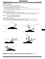
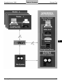
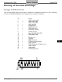
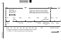
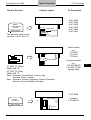
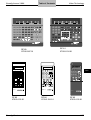
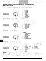
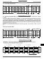
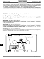
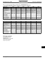
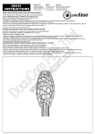
Audio Technology
Table of Contents
Grundig Annual 1998
Part 1 is used to check and adjust the tape speed by comparing it with the 50Hz mains
frequency (Lissajous figure displayed on the oscilloscope). A circle is shown at a tape speed
of 4.75cm/s, a horizontal eight at 9.5cm/s, and a four-pointed crown at 19cm/s.
The other parts on the test tape are used to check and adjust the tape speed with corresponding
measuring instrumentes (wow and flutter meter according to DIN 45507, GRUNDIG GA 1000).
GRUNDIG Head and Tape Run Gauges for Cassette Recorders
Head Gauge 034 (part no. 34000-034.00)
For setting the height and insertion depth of the AW-head for cassette recorders up to 1979/
80 models which correspond to the HiFi-standard with the exception of the models CN 700, CN
710, 720 and CN 730.
Head Gauge 180 (part no. 34074-180.00)
For setting the height and insertion depth of the AW-head of the HiFi models CF 5500/55002, MCF 500 and MCF 600.
Head Gauge 220, (part no. 34065-220.00)
For setting the height and insertion depth of the AW-head of the HiFi models CF 5000/50002, CF 5100, SCF 6000/6100 and SCF 6200, CF 4200, CCF 4300/MKII, CF 7100, CF 7200,
CF 7300, CF 7000/7400, CF 7150/7250 and CF 7500.
Head Gauge 401, (part no. 72008-401.00)
For setting and checking the height and insertion depth of the AW or AW-L head (rotating head),
the dummy head and the external tape guides of HiFi recorders.
Head Gauge 401
Slider A
Sensing Lever B
Audio
7.4
Grundig Service
Table of Contents
Grundig Annual 1998
Audio Technology
GRUNDIG Tele-Pilot®Remote Control Handsets/Survey of Types
Audio Product Range
PTY
POWER
y
1
TUNER
2
SHUFFLE REPEAT
SCAN
SCAN
g
TUNER
FN/AM
CD
R
y
SKIP
E
TUNER
SHUFFLE
SHUFFLE
CD
CD
DISC
DISC
OPEN/
OPEN/
CLOSE
CLOSE
O
MUTE
8
TIME
TIME
STATION
DISC
P
PAUSE
PAUSE
STATION
SCAN
B
STOP
STOP
9
PLAY
PLAY
DISC
TAPE
A
B
TAPE
Q
–
VOLUME
VOLUME
R
DCC
DECK A
DCC
PHONO
PRESETS
+
+
;
VOLUME
AUX
VOLUME
_
1
9
–
RC M5
AUX
+
a
COMPACT
COMPACT
DIGITAL
DIGITAL AUDIO
AUDIO
M2/M6-RC
M30/M40-RC
M30/M40-RC
59802-613.01
CDC 477 RC
75954-027.17
POWER
POWER 8
1
P
RE
5
6
9
0
3
7
8
SKIP
SEARCH
SLEEP
TAPE
AUX
REMAIN
RANDOM
REPEAT
FM
MW
MUTE
SKIP
SEARCH
PLAY/PAUSE
g3
f
f
STOP
Z
hVOLUMEg
+10
" TUNE !
CLOCK
CD
POWER
4
Z
CAN
DI S P
T/S
EA
LA
Y
2
CD
OM
ND
RA
RC M5
75952-022.10
MUTE
ON/OFF
INT
RO
M2/M6 RC
75954-028.68
BAND
SLEEP
PROG.
MUTE
AUTO/MANU.
SKIP
TUNING
1
2
3
4
5
6
TIME
PROGRAM
7
9
8
BAND
0
PRESET CH.
PHONO
FM
CDP
AUX
CLOCK
SLEEP
MW
TAPE
FUNCTION
P
t
P
O
DECK A
DECK B
CDP
REPEAT
O
PROG.
TUNER
CD
STOP
CDM 700
z
t
PLAY
PLAY
TAPE
d
A/B
FORWARD
STOP
f
REWIND
Z
PLAY/PAUSE
TAPE
+10
TAPE
VOLUME
LW
TAPE
VOLUME
P
Z
EQ ON/FLAT
FREQUENCY
EQ USER
EQ MEMORY
O
1
REMOTE CONTROL
DISPLAY
REPEAT
LW
AUTO/MAN.
PRESET
TUNING
EQ-MODE
VOLUME
&
LEVEL
%
R-MUTE
FUNCTION
MUTE
RC MC 10
CD PROG.
!
TIMER
ON/OFF
CLOCK
SET
TUNING
"
SET
1
Audio
RC 20
RC CDM 700
75954-062.93
Grundig Service
RC 10
75950-504.87
RC 20
75951-045.77
RC MC 10
75952-049.30
7.5
Table of Contents
Audio Technology
9
TAPE
Grundig Annual 1998
B
STOP
POWER
CD
REPEAT
RANDOM
MEMO
1
2
3
4
PLAY
NEXT
5
6
7
9
0
+10
VCR
TV
TUNER
SHUFFLE
DISC
PREV
REPEAT
NEXT
SEARCH
SCAN
8
ZZ
TT
2
DISC
TUNER
EQUALIZER
BAND
PRESET
TUNER
TAPE
%
SLEEP
g 3
SEARCH
+
VOLUME
STATION
TUNING
STOP
%
DECK A
CD
DISC
CD
PREV
PHONO
VOLUME
PLAY
PAUSE
PHONO
AUX
VOLUME
-
VOLUME
+
RC 680
RCM - SYSTEM
RC 670
CDM 3000/5000-RC
RCM-System
75954-003.10
CDM 3000/5000 RC
75954-029.95
RC 670
75951-030.50
RC 680
75953-800.15
OFF
POWER
CCF
TU
1
2
3
DECK A
ER
DECK B
N
MEMORY SCAN
MEMORY SCAN
4
TUNER
CD
5
6
7
CD
9
CD
0
E
OR
ST
AT
PE
F
TUNER
CC
RE
DOWN
UP
TUNING
N
TAPE
A
SC
DOWN
UP
MEMORY SCAN
P
AM
E
UN
T
R
/A
EO
UX
VID
DOWN
O
ON
PH
PE
TA
-
COMPACT
REMOTE CONTROL
1 CD
DECK A
EQUALIZER
-
VOLUME
+
E
DE
Audio
AUX
UP
VOLUME
M
LU
VO
CD
CK
A
MU
REMOTE CONTROL
+
R 220-RC
TUNER
CD
PHONO
DAT/TAPE
TAPE
MUTE
F
TE
ER
OF
W
PO
2
AMP
.............
.............
.............
.............
.............
.............
.............
.............
.............
.............
.............
.............
.............
REMOTE CONTROL RC
3
RC
RC
DIGITAL AUDIO
RC 1 CD
59800-749.01
7.6
STATION
8
RC 2
59800-767.00
RC 3
75987-588.15
R 220 RC
75954-010.50
Grundig Service
Table of Contents
Grundig Annual 1998
CD
CD
TUNER
DPL MODE TEST TONE
DISC UP
TV/VCR
TAPE 1/2
TUNER
AUX
SHUFFLE
TAPE 1
TAPE 2
SIDE
AUX/TV
DSC
CENTER
SLEEP
CENTER
1
2
4
INCREDIBLE
5
8
7
TUNER
PTY
< STATION >
TUNER
PTY
< STATION >
EQUALIZER
VOLUME
6
REAR
DBB
SLEEP
3
REAR
DSC
Audio Technology
CD
CD
TAPE
TAPE
9
SIDE
SOUND
0
VOLUME
AUX
AUX
VOLUME
PLAY
VOLUME
EQUALIZER
+
+
PLAY
PREV.
NEXT
PREV.
NEXT
STOP
VOL.TV
PAUSE
STOP
VOL.TV
VOL.TV
L
RC M 7/17/27 C
RC M18/28/38 C
RH 8809/00
75954-049.36
POWER
TUNER
TAPE
PAUSE
BALANCE
RC UMS
RC UMS
UMS1/2
75954-029.64
UMS11/12
75954-505.01
VOL.TV
BALANCE R
INC. SURR.
SHUFFLE
DBB
DISC UP
RC M 37 DC
RC M48 DC
RC 8623
75954-050.41
SHUFFLE
CD
POWER
BAND
P.SCAN
1
DISC
SKIP
FM
MODE
M.SCAN
2
3
1
SKIP
RANDOM
RANDOM REPEAT
TIME
PROG.
PROGRAM CLEAR
CHECK
2
4
5
7
REPEAT
TUNER/BAND
PRESET
TAPE
B.BOOST FM MODE
3
OPEN/
M/SCAN CLOSE
8
VOLUME
SLEEP
VOLUME
MUTE
6
7
8
9
SCAN
9
REPEAT
PAUSE
0
VOLUME
–
STOP
VOLUME
3
5
0
REPEAT
MUTE
2
4
6
SCAN
CLEAR
1
+
–
PLAY
VOLUME
+
PLAY
L
SHUFFLE
PREV.
NEXT
STOP
PAUSE
Audio
RC KM 11
75954-042.80
Grundig Service
RC KM12/13
75954-062.57
RC CD22
75954-069.11
RC CD 23
75954-069.18
7.7
Table of Contents
5
9
0
STATION
DSR/AUX
NEWS
AFF AIRS
1
2
EDUCA TE DRAMA
CD
4
6
7
8
VARIETY
9
POP M.
0
ROCK M.
EASY M.
MUSIC
OTHERS
STATION
PROGR.
LIGHT M. CLASSICS
1
2
3
4
5
1
2
3
4
5
6
7
8
9
0
6
7
8
9
0
REPEA T SHUFFLE
d
R
TUNING
E
CANCEL MEMOR Y
2
E
3
f
TAPE
SPOR T
3
5
F/DIRECT
2
INFO
CUL TURES SCIENCE
f
STATION
E
3
d
TV
4
8
P
SA T
3
7
P
VCR
2
6
TUNER
1
Grundig Annual 1998
P
P
P
P
d SURROUND
1
MODE
PTY
TUNER
Audio Technology
TXT/TV
INFO
R
E
STATION
TV/VCR
CD
TV
by
Fine Arts Tuner
59802-601.01
VOLUME
RC SYSTEM DPL
CD-PLA YER
1
8
by
Fine Arts CD-Player
59802-603.00
by
w
TUNER
1
VOLUME
w
SYSTEM
1
w
by
DISPLAY MODE
DCC/ DISPLA Y
DECK A MODE
Fine Arts System
59802-602.01
HIFI
AUX
a
VOLUME
8
a
TAPE
ANTENNA/ WIDE/
CABLE
NARROW
a
VOLUME
T
8 HIFI 8 SAT 8
PHONO
MONO/
MUTE
a
2
T
w
DCC
Z
BAND
8
3
Z
T
1
3
Z
1
DISPLA Y MODE
2
Fine Arts System DPL
59802-616.01
1
2
3
4
5
1
2
3
4
5
1
2
3
4
6
7
8
9
0
6
7
8
9
0
6
7
8
9
5
0
1
a
6
1
City Line System
59802-607.01
w1
VOLUME
city line
8
TV
SAT
VCR
–
Install
2
$
CENTRE
+
E
#
STATION
T
SYSTEM
DCC/ DISPLA Y
DECK A MODE
1
Grundig System
59802-608.01
7.8
3
a
VOLUME
SYSTEM
DCC/ DISPLA Y
DECK A MODE
Audio
Z
SURROUND
1 RECORD Z
a
3
HIFI
T
TV/VCR
URC 20
75954-068.56
VOLUME
A/V REMOTE CONTROL-URC1
DCC
1
a
8
2
E
E
P
REAR
w
R
d
TUNER/pty
E
E
3
TAPE 1 2 CD/disc
f
T
P
P
6
3
d
PHONO
DCC
Z
2
PHONO
TAPE
R
P
TXT/
f
2
DSR/AUX
E
3
CD
CD
2
P
STATION
TAPE
DSR/AUX
STATION
P
8 HIFI 8 SAT 8 TV
TUNER
TUNER
AV
M 100
59802-624.01
Grundig Service
Table of Contents
Grundig Annual 1998
Audio Technology
STOP
STBY/ON
9
S
CD
MEMORY
MEMORY
CD-COPY
CD-COPY
RECORD
RECORD
P L AY / PA U S E
R E P E AT
+
TUNER
T
2;
CD 1
CANCEL
CANCEL
PROG.
CD 2
STATION
CONTINUOUS
P L AY
TAPE
MODE
MODE
VOLUME
AUX
PTY
PTY
–
DISC
SOUND
CONTROL
CD
R E M O T E
POWER
SOUND
PA 1
75954-034.87
RC PA2/3
59802-619.01
C O N T R O L
K-RCD 500
75954-036.11
PLAY
STOP
TUNER
PTY
MEM. UP
1
2
3
4
5
6
7
8
9
PLAY
REPEAT
SLEEP
STOP
STATION
PREV./DOWN NEXT/UP
PREV.
NEXT
CD
–
DISC
VOLUME
+
VOLUME
0
TAPE
RC-CD437
-
VOLUME
+
RC 400
Audio
RC 400
75954-032.17
Grundig Service
RR 750 CD
75954-047.28
RR 3500 CD
RR 650 CD
75954-046.34
RC 437
75954-015.61
7.9
Audio Technology
Table of Contents
Grundig Annual 1998
Service Manuals from 1992 on: Audio/HiFi
Set
AS - IR
CCD 670
CCD 680
CCF 2
CCF 3
CCF 21 CITY LINE
CCF 23
CCF 101 A
CCF 101 A NEW ORLEANS
CCF 101 NEW ORLEANS CASS.
CCF 102
CCF 120
CCF 210
CCF 310
Audio
CD
1
CD
2
CD
3
CD 11
CD 12
CD 21 CITY LINE SAN REMO
CD 21
CD 22
CD 23
CD 102
CD 120
CD 210
CD 360
CD 435
CD 436
CD 437
CD 904
CD - IR
CD 1000
CDC 14
CDC 477
CDM 700
CDM 3000
CDM 5000
CDP 70
CDP 75
CDP 76
CDP 80
CDP 100
CDP 110
CDP 200
CDP 210
CDP-S 150
CDP-S 250
Service
Manual
72010-741.15
72010-735.05
72010-739.65
72010-735.10
72010-734.00
72010-737.10
72010-755.65
72010-733.10
72010-733.10
72010-730.05
72010-741.80
72010-741.40
72010-737.10
72010-737.50
72010-736.00
72010-736.01
72010-737.35
72010-737.36
72010-737.35
72010-737.36
72010-745.35
72010-745.50
72010-738.05
72010-755.55
72010-755.55
72010-756.35
72010-741.80
72010-741.40
72010-738.05
72010-733.00
72010-733.00
72010-745.75
72010-745.75
72010-732.20
72010-741.15
72010-745.70
72010-745.40
72010-745.90
72010-755.70
72010-747.15
72010-747.15
72010-737.30
72010-745.15
72010-755.10
72010-737.30
72010-738.45
72010-745.15
72010-743.85
72010-755.15
72010-752.70
72010-757.10
Observe also the instructions given in the Safety Service Manual Part No. 72010-800.00 (p.1.16pp)
7.10
Grundig Service
Grundig Annual 1998
Set
CF 1
CF 1 MK II
CF 4
CF 11
CF 21
CL-CCF 6 CITY LINE
CL-CD
CL-V
6 CITY LINE
6 CITY LINE
DCC 305
DSR 200
EQT 210
HEINZELMANN
K- RCD 100
K-CDP 65
K-CDP 66
K-RCD 110
K-RCD 120
K-RCD 500
KM 11
KM 12
KM 13
M 1
M 2
M 5
M 6
M 7-C
M 10
M 15
M 16
M 17-C
M 18-C
M 20
M 25 D/GB
M 26
M 27-C
M 28-C
M 30 CCF
M 30 CD
M 30-A
M 30-R
M 30-T
M 37-DC
M 38-C
M 40-CDC
M 48-DC
M 100 A
Table of Contents
Audio Technology
Service
Manual
72010-733.55
72010-740.05
72010-736.35
72010-744.70
72010-755.60
72010-735.10
72010-737.35
72010-737.36
72010-735.90
72010-735.91
72010-735.60
72010-012.20
72010-737.15
72010-745.10
72010-743.95
72010-743.90
72010-743.91
72010-755.05
72010-755.06
72010-749.90
72010-756.50
72010-748.45
72010-750.05
72010-754.30
72010-757.15
72010-738.60
72010-746.05
72010-738.65
72010-746.05
72010-752.25
72010-733.30
72010-740.60
72010-745.20
72010-740.60
72010-752.25
72010-755.85
72010-735.70
72010-735.71
72010-741.35
72010-745.25
72010-741.35
72010-752.25
72010-755.85
72010-740.75
72010-740.75
72010-740.75
72010-740.75
72010-740.75
72010-753.25
72010-755.85
72010-744.65
72010-755.85
72010-749.15
Audio
Observe also the instructions given in the Safety Service Manual Part No. 72010-800.00 (p.1.16pp)
Grundig Service
7.11
Audio Technology
Set
M 100 ADPL
M 100 CD
M 100-CD MKII
M 100 CDC
M 100 CF
M 100 R
M 100 T
MC 10
MC 10 GB
MINI 10
MINI 10 ORLANDO
PA 1
PA 2
PA 3
PRISMA XI
R 1
R 2
R 2 GB
R 3 FINE ARTS
R 6 CITY LINE
R 11
R 12
R 14 DPL
R 21
R 22 DPL
R 23 DPL
R 102
R 120
R 210
R 210 GB
R 220
R 303
R 310
R 1000 DPL
RAVENNA D/GB
RCD 400
RCD 405
RF 630
Audio
RR
RR
RR
RR
RR
RR
RR
RR
420 CD
600 CD
610 CD
620 CD
650 CD
700 CD
710 CD
750 CD
RR 1950 CD
RR 2000
RR 3000 CD
Table of Contents
Grundig Annual 1998
Service
Manual
72010-750.65
72010-749.80
72010-754.35
72010-750.70
72010-749.85
72010-749.15
72010-750.60
72010-738.00
72010-738.00
72010-733.30
72010-733.30
72010-748.40
72010-746.55
72010-746.55
72010-736.21
72010-733.50
72010-733.50
72010-733.50
72010-735.80
72010-735.80
72010-744.00
72010-744.00
72010-746.95
72010-755.90
72010-755.90
72010-757.20
72010-741.80
72010-741.40
72010-736.90
72010-736.90
72010-741.40
72010-720.80
72010-740.65
72010-745.65
72010-733.30
72010-747.05
72010-752.30
72010-739.35
72010-739.36
72010-752.40
72010-732.85
72010-738.20
72010-751.70
72010-751.70
72010-739.60
72010-751.75
72010-751.75
72010-718.35
72010-718.36
72010-738.25
72010-732.90
Observe also the instructions given in the Safety Service Manual Part No. 72010-800.00 (p.1.16pp)
7.12
Grundig Service
Grundig Annual 1998
Set
RR 3100 CD
RR 3200 CD
RR 3500 CD
RR 4000 CD
SC 900
SC 910
ST 16 (ADR)
ST 303
T 1
T 2
T 4
T 6
T 12
T 21 CITY LINE SAN REMO
T 22
T 210
T 310
T - IR
T 1000
TT 1
UMS 1
UMS 2
UMS 11
UMS 12
UMS 12-S
V 1
V 2
V
3
V 4
V 11
V 12
V 14 DPL-RF
RBX-1
V 21
V 23
V 101 A
V 101 A NEW ORLEANS AMP:
V 210
V 210 GB
V 310
V 310 GB
V 1000 DPL
YACHT BOY 360
YACHT BOY 400
YACHT BOY 500
Yacht Boy-P2000
Table of Contents
Audio Technology
Service
Manual
72010-738.30
72010-751.80
72010-751.80
72010-739.40
72010-754.45
72010-754.40
72010-752.10
72010-732.15
72010-733.45
72010-733.45
72010-735.85
72010-514.65
72010-742.65
72010-737.55
72010-755.40
72010-737.55
72010-737.55
72010-741.15
72010-745.55
72010-740.70
72010-748.20
72010-748.20
72010-757.25
72010-757.25
72010-757.25
72010-733.15
72010-735.35
72010-735.90
72010-735.91
72010-740.40
72010-742.45
72010-742.45
72010-752.15
72010-752.20
72010-755.45
72010-755.50
72010-732.95
72010-732.95
72010-736.75
72010-736.75
72010-736.75
72010-736.75
72010-745.65
72010-745.05
72010-739.25
72010-735.00
72010-757.00
Audio
Observe also the instructions given in the Safety Service Manual Part No. 72010-800.00 (p.1.16pp)
Grundig Service
7.13
Audio Technology
Table of Contents
Grundig Annual 1998
Service Manual from 1992 on: Car Audio
Set
BOOSTER PA 120
BOOSTER PA 240
EC 4000 RDS
EC 4290 CD
EC 4600 RDS
EC 7400 RDS
EC 7500 RDS
MCD 20
MCD 30
Audio
MCD 36
MCD 40
SCD 1590 VD
SCD 1910 RDS
SCD 3590
SCD 5260 RDS
WKC 1100 VD
WKC 1101 VD
WKC 1102 VD
WKC 1630
WKC 1650 VD
WKC 1670 VD
WKC 1700 VD
WKC 1701 VD
WKC 1703 RDS
WKC 1703 RDS / RS
WKC 1704 RDS
WKC 1704 RDS / RS
WKC 1705 RDS
WKC 1903 RDS
WKC 1904 RDS
WKC 3100
WKC 3101
WKC 3102
WKC 3200
WKC 3201
WKC 3300
WKC 3301
WKC 3600
WKC 3630
WKC 3650
WKC 3700
WKC 3700 R
WKC 3701
WKC 3701 R
WKC 3703 RDS RS
WKC 3704 RDS RS
WKC 3705 RDS RS
WKC 3705 RDS RS
WKC 3870 RDS
WKC 3880 RDS
WKC 3880 RDS (MCD-A1)
Service Manual
72010-731.95
72010-732.00
72010-748.50
72010-750.55
72010-748.50
72010-752.75
72010-739.50
72010-739.50
72010-733.60
72010-737.25
72010-737.26
72010-748.30
72010-748.30
72010-739.10
72010-733.20
72010-739.10
72010-749.35
72010-739.70
72010-739.40
72010-741.95
72010-744.95
72010-736.10
72010-738.70
72010-791.85
72010-791.85
72010-738.15
72010-738.15
72010-738.15
72010-738.15
72010-740.35
72010-731.05
72010-736.05
72010-739.40
72010-739.70
72010-741.95
72010-752.45
72010-752.45
72010-752.45
72010-752.45
72010-749.15
72010-744.95
72010-736.10
72010-730.60
72010-730.60
72010-740.20
72010-730.65
72010-738.15
72010-738.15
72010-740.35
72010-740.35
72010-720.50
72010-730.55
72010-730.55
Observe also the instructions given in the Safety Service Manual Part No. 72010-800.00 (p.1.16pp)
7.14
Grundig Service
Grundig Annual 1998
Set
WKC 3904 RDS
WKC 3905 RDS
WKC 4871 RDS
WKC 5100
WKC 5101
WKC 5200
WKC 5201
WKC 5300
WKC 5600
WKC 6400 RDS
WKC 6500 RDS
Table of Contents
Audio Technology
Service Manual
72010-731.80
72010-731.85
72010-731.70
72010-720.00
72010-720.01
72010-746.36
72010-746.36
72010-746.36
72010-746.36
72010-746.30
72010-746.30
72010-740.00
72010-740.00
Audio
Observe also the instructions given in the Safety Service Manual Part No. 72010-800.00 (p.1.16pp)
Grundig Service
7.15
Table of Contents
Audio Technology
Grundig Annual 1998
1650 VD
1670 VD
1703 RDS/RS
1704 RDS/RS
1705 RDS
1903 RDS
1904 RDS
1905 RDS
1910 RDS
•
•
•
•
•
•
•
2632 VD
2642 VD
2670 VD
2680 VD
2803 VD/A
2804 VD
2805 VD
2841 VD
2842 VD
2845 VD
3851 RDS
3860 VD/aVD
3870 RDS
3880 RDS
3904 RDS
3905 RDS
4804 VD
4805 VD
4870 RDS/A/C
4871 RDS
5500 RDS/A/C
6400 RDS
6500 RDS
Audio
7400 RDS
7500 RDS
5100 RDS
5101 RDS
5200 RDS
5201 RDS
5290 RDS
5300 RDS
5390 RDS
7.16
•
•
•
•
•
•
•
•
•
•
•
•
•
•
•
•
•
•
•
•
•
•
•
•
•
•
•
•
•
•
•
from 845501
•
•
5600 RDS
5690 RDS
4000 RDS
•
•
4290 RDS
4600 RDS
3200 RDS
3201 RDS
3300 RDS
3301 RDS
•
•
•
•
•
•
•
•
•
•
•
•
•
•
•
•
•
•
Quick-out Unit 3)
Optional Code Number 1)
Quick-out Unit 3)
•
Removable Control Panel
1630 VD
Type of Car Radio
WKC/SCD/EC..
Specific Code Number 2)
•
•
•
•
•
•
•
•
•
•
•
1590 VD
Removable Control Panel
Specific Code Number 2)
Type of Car Radio
WKC/SCD/EC..
Optional Code Number 1)
Grundig Anti-theft Systems for Car Radios
•
•
RS
RS
•
•
•
•
•
•
•
•
•
•
•
•
•
•
•
•
•
•
•
•
•
•
•
RS
RS
RS
1) It is possible to enter any code number as four figures
2) The car radios are given a 4-place code number at the factory
which cannot be changed
3) Quick-out plug-in unit. You can withdraw the car radio easily
from the compartment by a handle and take it along with you.
RS plug-in unit, order no. G.IB.02-97
Grundig Service
Activating the coding
1. Radio is playing
BAND 3)
2. Press button 1) for more than 3 seconds
"CODE" appears in the display
1_ _ _
After 3 seconds the display shows 1)
3. Enter the code number
The code number is entered by repeatedly
pressing the station buttons 1-4 (station
button 1 for figure 1, station button 2 for
figure 2 a.s.o.). A wrong code number can be
corrected by overwriting, i.e. by a new entry
4. Confirm the code number
BAND
Press button 1) for more than 3 seconds
"SAFE" appears in the display
Is the coding activated?
1. Radio is playing
2. Press button 1) for more than 3 seconds
a. The coding is activated if
"SAFE" appears in the display
After 3 seconds the display shows 1)
Switch the radio off/on - radio starts playing
b. The coding is not activated if
"CODE" appears in the display
After 3 seconds the display shows 1)
Switch the radio off/on - radio starts playing
1703, 1704, 1705
1910, 7400, 7500
1903, 3904, 3905
1630, 1650, 1670
2803, 2804, 2670
2680, 4804
2841 (DS2)
2842
Audio Technology
U-M 3)
U-M
FM
U
U
U
FM
1__ _
1_ _ _
____
1___
1___
____
____
U-M
U-M
FM
U
U
U
FM
BAND
U-M
U-M
FM
U
U
U
FM
81 _ _ _
81 _ _ _
11 _ _ _ 1 _ _ _ _
1___
1_ _ _ _
____
1___
1___
____
____
1___
1___
1____ ____
5)
1___
1
1___
Putting into operation again
On disconnection from the supply voltage the
radio is electronically locked.
1. Reconnect the radio correctly to the supply
voltage.
2. Switch the radio on
"SAFE" appears in the display
81 _ _ _
After 3 seconds the display shows 1)
3. Enter the code number
4. Confirm the code number
BAND
Press button 1) for more than 3 seconds
"SAFE" appears in the display
After approx. 3 seconds - radio starts playing
If the code number entered is not correct
"SAFE" appears in the display
7
After a waiting time the counter 4) indicates
Deactivating the coding
1. Radio is playing
2. Press button 1) for more than 3 seconds
"SAFE" appears in the display
After approx. 3 seconds the display shows 1)
3. Enter the code number
4. Confirm the code number
Press button 1) for more than 3 seconds
After approx. 3 seconds - radio starts playing
If the code number entered is not correct
"SAFE" appears in the display
After a waiting time the counter 4) indicates
2841 (DS1),
2845 2)
3860 VD
and Variants 2)
The following is a description of the
coding and decoding methods for the
different types of car radios.
Type of Car Radio
WKC/SCD/EC . .
Anti-theft Coding
of Car Radios
4870, 5500, 5000,
3851, 3870, 3880,
4871, 6400, 6500
Table of Contents
Grundig Annual 1998
1___
1___
____
81 _ _ _
1___
1____
1
U-M
U-M
FM
U
U
U
FM
7
2
2
2
1
2
1
BAND
U-M
U-M
FM
U
U
U
FM
81 _ _ _
81 _ _ _
11 _ _ _ 1 _ _ _ _
1___
1___
1____ ____
1
BAND
U-M
U-M
FM
U
U
U
FM
7
7
2
2
2
1
2
1
Audio
1) see chart opposite 2) Car radios with optional code number (anti-theft system1) 3) The coding screw has to be loosened before
entering the code number 4) The figure on the left of the code number indicates the number of attempts counted.
Between the attempts 1-7 the waiting time increases to 24 hours. After the 7th attempt there is always a waiting period of 24 hours
until a new code can be entered. Car radios with anti-theft system 1 allow a maximum of 8 attempts. After the 8th attempt the radio
must be returned to the factory for decoding. 5) The coding is activated when "SAFE" flashes in the display with the car radio
switched off.
Grundig Service
7.17
Activating the Coding
1. Radio is playing
2. Press button 1) for more than 1 second, select
"CODE" on the display with the rotary knob
Press button 1) shortly - the display shows 1)
3. Enter the code number
The code is entered by repeatedly pressing
the station buttons 1-4 (station button 1 for
figure 1, station button 2 for figure 2 a.s.o.)
A wrong code number can be corrected by
overwriting, i.e. by a new entry
4. Confirm the code number
Press button 1) shortly
"SAFE" appears in the display
To leave the Expert Mode:
Press button 1) for more than 1 second
Is the coding activated?
1. Radio is playing
2. Press button 1) for more than 1 second
a. The coding is activated if
"SAFE" appears in the display
b. The coding is not activated if
"CODE" appears in the display
To leave the Expert Mode:
Press button 1) for more than 1 second
Putting into operation again
On disconnection of the supply voltage the
radio is electronically locked.
1. Reconnect the radio correctly to the supply
voltage.
2. Switch the radio on
"SAFE" appears in the display
After approx. 3 seconds the display shows 1)
3. Enter the code number
4. Confirm the code number
Press button 1) shortly
"SAFE" appears in the display
After approx. 3 seconds - radio starts playing
If the code number entered is not correct
"SAFE" appears in the display
After a waiting time the counter 4) indicates
Audio
Deactivating the coding
1. Radio is playing
2. Press button 1) for more than 1 second, select
"SAFE" on the display with the rotary knob
3. Press button 1) shortly
The display shows 1)
4. Enter the code number
5. Confirm the code number
Press button 1) shortly
"CODE" appears in the display
If the code number entered is not correct
"SAFE" appears in the display
After a waiting time the counter 4) indicates
6. Press button 1) for more than 1 second
EXPERT
E -- -- -- --
EXPERT
The following is a description of the
coding and decoding methods for the
different types of car radios.
4000, 4290, 4600
5100, 5101, 5200,
5201, 5290, 5300,
5390, 5600, 5690
The following is a description of the
coding and decoding methods for the
different types of car radios.
Type of Car Radio
WKC/SCD/EC . .
Anti-theft Coding
of Car Radios
Grundig Annual 1998
Type of Car Radio
WKC/SCD/EC . .
Table of Contents
Audio Technology
Activating the Coding
1. Radio is playing
2. Press button 1) for more than 1 second, select
(EXPERT)
"CODE" on the display with the right rotary
knob
Press button 1) shortly - the display shows 1) CH -- -- -- -3. Enter the code number by turning the right
shaft encoder
4. Confirm the code number
Press button 1) shortly
Right shaft
"SAFE" appears in the display
encoder
To leave the Expert Mode:
Press button 1) for more than 1 second
(EXPERT)
EXPERT
EXPERT
EXPERT
1-- -- -- --
EXPERT
2
EXPERT
EXPERT
E 1-- -- -- --
EXPERT
2
EXPERT
Is the coding activated?
1. Radio is playing
2. Press button 1) for more than 1 second
a. The coding is activated if
"SAFE" appears in the display
b. The coding is not activated if
"CODE" appears in the display
To leave the Expert Mode:
Press button 1) for more than 1 second
(EXPERT)
(EXPERT)
Putting into operation again
On disconnection of the supply voltage the
radio is electronically locked.
1. Reconnect the radio correctly to the supply
voltage.
2. Switch the radio on
"SAFE" appears in the display
After approx. 1 second the display shows 1)
1 -- -- -- -3. Enter the code number with the shaft encoder
4. Confirm the code number
Press button 1) for approx. 1 second
Right shaft
"SAFE" appears in the display
encoder
After approx. 1 second - radio starts playing
If the code number entered is not correct
"SAFE" appears in the display
After a waiting time the counter 4) indicates
2
Deactivating the coding
1. Radio is playing
2. Press button 1) for more than 1 second, select
(EXPERT)
"SAFE" on the display with the rotary knob
3. Press button 1) shortly
Right shaft enc.
The display shows 1)
CH 1-- -- -- -4. Enter the code number with the shaft encoder
5. Confirm the code number
Press button 1) shortly
Right shaft enc.
"CODE" appears in the display
If the code number entered is not correct
"SAFE" appears in the display
After a waiting time the counter 4) indicates
2
6. Press button 1) for more than 1 second
(EXPERT)
1) see chart opposite 4) The figure on the left of the code number indicates the number of attempts counted.
Between the attempts 1-7 the waiting time increases to 24 hours. After the 7th attempt there is always a waiting period of 24 hours
until a new code can be entered.
7.18
Grundig Service
Table of Contents
The following is a description of the
coding and decoding methods for the
different types of car radios
Activating the coding
1. Radio is playing
2. Press button 1) until a signal is sounded.
"EXPERT" appears shortly in the display.
Press one of the buttons 1) until "CODE"
appears in the display. Press button 1) shortly.
The indication 1) flashes in the display
3. Enter the code number
The code is entered by repeatedly pressing
the station buttons 1-4 (station button 1 for
figure 1, station button 2 for figure 2 a.s.o.)
A wrong code number can be corrected by
overwriting, i.e. by a new entry
4. Confirm the code number
Press button 1) shortly
"SAFE" appears in the display
To leave the Expert Mode:
Press button 1) until a signal is sounded.
Is the coding activated?
1. Radio is playing
2. Press button 1) for more than 1 second
a. The coding is activated if
"SAFE" appears in the display
b. The coding is not activated if
"CODE" appears in the display
To leave the Expert Mode:
Press button 1) for more than 1 second
Putting into operation again
On disconnection from the supply voltage the
radio is electronically locked.
1. Reconnect the radio correctly to the supply
voltage.
2. Switch the radio on
"SAFE" appears in the display
After approx. 3 seconds the display shows 1)
3. Enter the code number - see above
4. Confirm the code number
Press button 1) until display shows "SAFE"
After approx. 2 seconds - Radio starts playing
The code number entered is not correct
"SAFE" appears in the display
After a waiting period the counter 4) indicates
Deactivating the coding
1. Radio is playing
2. Press button 1) until a signal is sounded.
"EXPERT" appears shortly in the display.
Press one of the buttons 1) until "SAFE"
appears in the display. Press button 1) shortly.
The indication 1) appears in the display
3. Enter the code number - see above
4. Confirm the code number
Press button 1) shortly
The display shows 1)
To leave the Expert Mode:
Press button 1) until a signal is sounded.
Audio Technology
3200, 3201, 3300
3301
Anti-theft Coding
of Car Radios
Type of Car Radio
WKC/SCD/EC . .
Grundig Annual 1998
EXPERT
EXPERT
-- -- -- --
EXPERT
EXPERT
EXPERT
EXPERT
1-- -- -- --
EXPERT
2
EXPERT
EXPERT
1-- -- -- --
Audio
EXPERT
"CODE"
EXPERT
1) see chart opposite 4) The figure on the left of the code number indicates the number of attempts counted.
Between the attempts 1-7 the waiting period increases to 24 hours. After the 7th attempt there is always a waiting period of 24 hours
until a new code can be entered.
Grundig Service
7.19
Audio Technology
Table of Contents
Grundig Annual 1998
Anti-theft Coding of Car Radios
The following is a description of the coding and decoding methods for the different types of car
radios.
Type of car radio: SCD 1590 VD
Entering the code number (initial operation):
1.
Switch the radio on.
The indication "CODE" appears on the display.
2.
Press station button 1 quickly.
The display shows "000".
3.
Enter the code number with the station buttons 1-4.
4.
Confirm the code number with the right station search button >.
Activating the coding:
1.
Switch the radio off.
2.
Press and hold the station buttons 1 and 4 simultaneously.
3.
Switch the radio on.
The indication "Cod" appears after 2 seconds on the display.
Deactivating the coding:
1.
Switch the radio off.
2.
Press and hold the station buttons 1 and 4 simultaneously.
3.
Switch the radio on.
The indication "Cod" appears on the display
4.
Enter the code number with the station buttons 1-4.
5.
Confirm the code number with the right station search button >.
Please refer to the table for other coding procedures.
Audio
7.20
Grundig Service
Grundig Annual 1998
Table of Contents
Electronic Appliances
Contents Electronic Appliances:
Summery of Products:
Men´s Shaver .................................................................................................. 8.2
Hair Trimmer ..................................................................................................... 8.5
Beard Trimmer ................................................................................................. 8.5
Lady Shaver/Epilation ...................................................................................... 8.6
Hair Dryers ...................................................................................................... 8.7
Electrical Tooth Brush ...................................................................................... 8.7
Accessories ..................................................................................................... 8.8
The most important Spare Parts for Grundig Shavers .................................. 8.12
Electronic
Appliances
Grundig Service
8.1
Electronic Appliances
Table of Contents
Grundig Annual 1998
Men´s Shaver
Model
PRO avantgarde
Colour: chrome, mat
EAN No.
400367242127 8
PRO Schumacher Coll.
Colour: anthracite
EAN No.
400367242129 2
PRO
Colour: anthracite
EAN No.
400367242131 5
PRO avantgarde
Colour: chrome mat
Electronic
Appliances
EAN No.
400367242133 9
8.2
Type Order No. Product Description
8875 RPY 8875 Battery and mains operation
Modern design, ergonomic
Metal shaving head frame
Vibra-rotation system
Rolling shutter, protection and on/off switch in one
Cutter blade with optimum cutting angle
Battery charge indicator, LCD
Platinum-plated shaver blade
2-stage combi-cut trimmer
12-24 Volt charging voltage for car and boat
Mains operation (100-240 Volt) is possible
60-MIN. QUICK CHARGE
Deluxe case with mirror
incl. wall bracket
8675 RPY 8675 Grundig Special Edition
Battery and mains operation
MS
MS
Modern design, ergonomic
Metal shaving head frame
Vibra-rotation system
Rolling shutter, protection and on/off switch in one
Cutter blade with optimum cutting angle
Battery charge indicator and recharge request, LED
Platinum-plated shaver blade
2-stage combi-cut trimmer
12-24 Volt charging voltage for car and boat
Mains operation (100-240 Volt) is possible
60-MIN. QUICK CHARGE
Deluxe case with mirror
8675 RPY 8675 Battery and mains operation
Modern design, ergonomic
Metal shaving head frame
Vibra-rotation system
Rolling shutter, protection and on/off switch in one
Cutter blade with optimum cutting angle
Battery charge indicator and recharge request, LED
Platinum-plated shaver blade
2-stage combi-cut trimmer
12-24 Volt charging voltage for car and boat
Mains operation (100-240 Volt) is possible
60-MIN. QUICK CHARGE
Deluxe case with mirror
8375 RPY 8375 Mains operation
Modern design, ergonomic
Metal shaving head frame
Vibra-rotation system
Rolling shutter, protection and on/off switch in one
Cutter blade with optimum cutting angle
Platinum-plated shaver blade
2-stage combi-cut trimmer
Automatic voltage adapter
(100-240 Volt)
Deluxe case with mirror
Grundig Service
Table of Contents
Grundig Annual 1998
Model
roltronic PRO
Colour: granite
EAN No.
400367234912 1
roltronic PRO
Colour: bornite
EAN No.
400367234911 4
double head plus
Colour: black
EAN No.
400367238242 5
double head plus
Colour: black
EAN No.
400367238243 2
Type
7645
7345
6655
6355
Electronic Appliances
Order No. Product Description
RPY 7645 Battery and mains operation
Glass-fibre reinforced shaving head frame
Two–way–cut system
Rolling shutter, protection and on/off switch in one
Cutter blade with optimum cutting angle
Charge indicator and recharge request LED
Platinum-plated shaver blade
Super-wide hair trimmer
12-24 Volt charging voltage for car and boat
Mains operation (100-240 Volt) is possible
60-MIN. QUICK CHARGE
Handy case with mirror for travels
RPY 7345 Mains operation
Glass-fibre reinforced shaving head frame
Two–way–cut system
Rolling shutter, protection and on/off switch in one
Cutter blade with optimum cutting angle
Platinum-plated shaver blade
Super-wide hair trimmer
Automatic voltage adapter
(100-240 Volt)
Handy case with mirror for travels
RPY 6655 Battery and mains operation
Double head
Glass-fibre reinforced shaving head frame
Counter-directional cutter blocks
"Green" power cell in line with the environment
LED battery charge and full-charge indicator
Visual and acoustic recharge request signal
Platinum-plated shaving foil basket
Far extending telescope long-hair trimmer
12-24 Volt charging voltage for car and boat
Mains operation (100-240 Volt) is possible
60-MIN. QUICK CHARGE
Elegant flat case with flap for cable
RPY 6355 Mains operation
Double head
Glass-fibre reinforced shaving head frame
Counter-directional cutter blocks
Platinum-plated shaving foil basket
Far extending telescope long-hair trimmer
Automatic voltage adapter 100-240 Volt
Elegant flat case with flap for cable
Electronic
Appliances
Grundig Service
8.3
Table of Contents
Electronic Appliances
Model
sportsline 6563
Colour: blue
EAN No.
400367240850 7
sportsline 6363
Colour: blue
EAN No.
400367240849 5
roltronic journey
EAN 400367238248 7
EAN 400367238247 0
EAN 400367242076 9
single head
Colour: green
EAN No.
400367240848 4
single head
Colour: green
Electronic
Appliances
EAN No.
400367240847 7
8.4
Type
6563
6363
6155
6154
6163
5563
5363
Grundig Annual 1998
Order No. Product Description
RPY 6563 Battery and mains operation
Double head
Glass-fibre reinforced shaving head frame
Shaving foil basket
Charge indicator (LED)
Battery full-charge indicator (on completion of the
charging process the signal lamp flashes)
60 min. battery quick charge
Mains operation (100 – 240 Volt) is possible
Far extending long-hair trimmer
Elegant flat case with flap for cable
RPY 6363 Mains operation
Double head
Glass-fibre reinforced shaving head frame
Shaving foil basket
Switchable from 110/120 to 220/240 Volt
Far extending long-hair trimmer
Elegant flat case with flap for cable
RPY 6155 Colour: bordeaux, bicolour design
RPY 6154 Colour: petrol, bicolour design
RPY 6163 Colour: black
Battery operation
Rolling shutter, protection and on/off switch in one
Shaving foil basket
Bicolour design
Superflat shape
Battery operation with 2 mignon cells or
2 NiCd cells (not included in the delivery)
Integrated small cleaning brush
RPY 5563 Battery and mains operation
Glass-fibre reinforced shaving head frame
Shaving foil basket
Charge indicator (LED)
Battery full-charge indicator (on completion of the
charging process the charge signal lamp flashes)
60 min. battery quick charge
Mains operation (100 - 240Volt) is possible
Far extending long-hair trimmer
Elegant flat case with flap for cable
RPY 5363 Mains operation
Glass-fibre reinforced shaving head frame
Shaving foil basket
Switchable from 110/120 to 220/240 Volt
Far extending long-hair trimmer
Elegant flat case with flap for cable
Grundig Service
Table of Contents
Grundig Annual 1998
Electronic Appliances
Hair Trimmers
Model
hairstyle
Colour: black
EAN No.
400367240846 0
hairstyle
Colour: black
Type
4565
4365
EAN No.
400367240845 3
Order No. Product Description
RPY 4565 Battery and mains operation - top class
Charging station (and appliance holder in one)
Solid detachable blade set
precision-ground for an extremely long lifetime
"Green" power cell in line with the environment
(approx. 50 min. operating time)
Automatic voltage adapter 100-240V
Attachable comb with 8 steps
Integrated cutting length adjustment, possible settings
2, 4, 7, 10, 13, 16, 22mm
Practical case
Small oil bottle, small cleaning brush
RPY 4365 Mains operation - top class
Solid detachable blade set
precision-ground for an extremely long lifetime
Automatic voltage adapter 100-240V
Attachable comb with 8 steps
Integrated cutting length adjustment, possible settings
2, 4, 7, 10, 13, 16, 22mm
Practical case
Small oil bottle, small cleaning brush
Beard Trimmers
Model
thema universal
Colour: black
EAN No.
400367234914 5
thema battery
Colour: black
EAN No.
400367234915 2
Beard trimmer, mains
Colour: black
EAN No.
400367240369 4
Grundig Service
Type
4543
4143
4363
Order No. Product Description
RPY 4543 Battery and mains operation
"Green" power cell in line with the environment
Detachable blade set
Attachable long-hair trimmer
Cutting length 2.5-15 mm
Solid blade set
Charge signal lamp
Travelling case
RPY 4143 Battery operation
Attachable long-hair trimmer
Cutting length 2.5-15 mm
Solid blade set
Battery operation with 3 mignon cells or
3 NiCd cells (not included in the delivery)
Travelling case
RPY 4363 Mains operation
Solid and detachable blade set
Detachable vario comb/5 settings
from 3 to 15 mm
Travelling case
Electronic
Appliances
8.5
Table of Contents
Electronic Appliances
Grundig Annual 1998
Lady Shaver/Epilation
Model
lady care wet & dry
Colour: mint
EAN No.
400367240626 8
lady care wet & dry
Colour: turquois
EAN No.
400367240625 1
lady care epilation
Colour: emerald-green
Type
2465
2165
2275
EAN No.
400367242101 8
Order No. Product Description
RPY 2465 Battery operation
For wet and dry shave
Charging station/appliance holder
Green power cell (NiMH) in line with the environment
Multi-functional improved shaving system for:
– the arms
– the legs
– the armpit zone
– bikini line hairs
Elegant soft pouch and small cleaning brush
RPY 2165 Battery operation
For wet and dry shave
Operation with 2 mignon cells or
with two NiCd cells (not included in the delivery)
Multi-functional improved shaving system for:
– the arms
– the legs
– the armpit zone
– and bikini line hairs
Elegant soft pouch and small cleaning brush
RPY 2275 Mains operation
Attractive elegant design
Two speeds
=-I. fine hairs
=-II. coarser hairs
Epilation method based on tweezers principle
Transformer 220 Volt to low-voltage safety operation
Practical case
Special Offers lady care
Model
lady care classic line
EAN 400367231900 1
EAN 400367231800 4
EAN 400367232405 0
Type
Order No. Product Description
2632
2614
4270
RPY 1900 Battery and mains operation
RPY 1800 Switchable to 110V/220V mains supply
RPY 4270 Battery operation
Cosmetic look
Multi-functional shaving system for:
- the armpit zone
- short, fine hairs
- the legs
Small cleaning brush
Type 2632 and 2614 with travelling case
Electronic
Appliances
8.6
Grundig Service
Table of Contents
Grundig Annual 1998
Electronic Appliances
Hair Dryers
Model
hairdress pro
Type
3765
professional 1500 hairdryer
EAN No.
400367241581 9
hairdress travel
Colour: black
EAN No.
400367235117 9
freestyle 6 in1
Colour: white/
calypso-red
3345
3455
EAN No.
400367239410 7
Order No. Product Description
RPY 3765 1500 W longlife motor
230 V, 50-60 Hz
Professional hairdressers results with profi features
3 heat settings (incl. real cold)
2 speed settings
Extremely narrow concentrator nozzle
Extra long cable (3 metres)
Removable air filter
Hanging loop
RPY 3345 1000 W hand-held hair dryer with
folding handle especially designed for travels
Switchable to 110-120/230-240 V, 50-60 Hz
2 heat settings with indicator
Air concentrator nozzle
2 adapters
Bag/pouch
Hanging loop
RPY 3455 Hair styling set for many applications
Six different attachments for styling
- zig-zags
- curls
- waves
- spirals
- straightening
- crimps
Electrical Tooth Brush
Model
vario clean
Type
1365
EAN No.
400376241359 4
Replacement brushes
GS 13
Grundig Service
Order No. Product Description
RPY 1365 Toothbrush, battery operation
Optimum plaque removal
Works on oscillating round brush principle
Vario clean: 2 settings;
70° Intensive (for healthy gums)
40° Gentle (for sensitive gums and
for massaging the gums)
4 attachable toothbrushes
Automatic voltage adjustment 100 - 240V
1 hour operating time when fully charged
Metal-free anchored Multiluft brushes with optimum
brush rounding
RPZ 1300 Replacement brush for vario clean 1365 with extra
brush head, exchangeable
Doubled lifetime
Available in 4 different colours: mint, blue, pink, lilac
Electronic
Appliances
8.7
Table of Contents
Electronic Appliances
Grundig Annual 1998
Accessories Men´s Shaver
Shaver blades
EAN No.
400367232794 5
EAN No.
400367238601 0
EAN No.
400367240734 0
EAN No.
400367226732 6
EAN No.
400367225263 6
Type Order No. Product Description
GS 80 RPS 8000 Shaving foil basket platinum-plated for
roltronic PRO
8835, 8635, 8345, 8335, 7658, 7645, 7345
PRO avantgarde 8875, 8675, 8375
GS 63 RPS 6300 Shaving foil basket platinum-plated for
double head plus 6655, 6355,
sportsline 6563, 6363
GS 53 RPS 5300 Shaving foil basket for
single head 5563, 5363
GS 21 RPY 2400 Shaving foil basket platinum-plated for
Alpha 3; Beta 3; roltronic, all G 8255;
roltronic Universal G 8264 - C/D/E/EK/G;
G 8265/8267
G 8242/G 8243
6335/6536
6154/6155
GS 20 RPY 1700 Shaving foil basket platinum-plated for
Alpha 1/2; Beta 1/2; roltronic G 8254;
roltronic Universal G 8264/A and B;
Accent
GS 16 RPV 1300 Shaver blade for Delta G 8262, G 8263
EAN No.
400367222930 0
GS 14 RPV 1200 Shaver blade for Gamma G 8240, G 8241
EAN No.
400367222929 4
GS 3
EAN No.
400367222928 7
RPV 1100 Shaver blade for Alpha G 8225, G 8229 and
Beta G 8234, G 8235
Electronic
Appliances
8.8
Grundig Service
Table of Contents
Grundig Annual 1998
Cutter blocks
EAN No.
400367232795 2
EAN No.
400367238602 7
EAN No.
400367240736 4
EAN No.
400367240735 7
EAN No.
400367238674 4
Electronic Appliances
Type Order No. Product Description
GS 81 RPS 8100 Precision-ground cutter for
roltronic PRO
8835, 8635, 8345, 8335, 7658, 7645, 7345
PRO avantgarde 8875, 8675, 8375
GS 64 RPS 6400 Cutter blocks for
double head plus 6655, 6355
GS 68 RPS 6800 Double cutter block for
sportsline 6563, 6363
GS 54 RPS 5400 Cutter block for
single head 5563, 5363
GS 66 RPS 6600 Cutter block for 6154/6155
all roltronic models
alpha 1/2/3, beta 1/2/3, Accent
GS 9 RPV 1600 Cutter block for Delta G 8262, G 8263
EAN No.
400367222933 1
GS 8
RPV 1500 Cutter block for Gamma G 8240, G 8241
GS 7
RPV 1400 Cutter block for Alpha G 8225, G 8229 and
Beta G 8234, G 8235
EAN No.
400367222932 4
EAN No.
400367222931 7
Electronic
Appliances
Grundig Service
8.9
Electronic Appliances
Other Accessories
EAN No.
400367242135 3
EAN No.
400367234349 5
EAN No.
400367239690 3
EAN No.
400367231330 6
EAN No.
400367224728 1
EAN No.
400367224727 4
EAN No.
400367224726 7
EAN No.
400367222934 8
EAN No.
400367238521 1
EAN No.
400367238618 8
Table of Contents
Grundig Annual 1998
Type Order No. Product Description
GS 84 RPZ 8400 Wall bracket for PRO avantgarde
Colour: black
GS 61 RPZ 6100 Wall bracket for roltronic PRO
Colour: black
GS 67 RPZ 6700 Wall bracket for
double head plus 6655, 6355
sportsline 6563, 6363
single head 5563, 5363
GS 60 RPY 5800 Wall bracket for all types of roltronic Universal
battery/mains
Colour: black
GS 58 RPX 1300 Wall bracket for all roltronic mains;
mains de Luxe
Colour: black
GS 57 RPX 1200 Wall bracket for Alpha 2/3; Beta 2/3
Colour: grey
GS 56 RPX 1100 Wall bracket for Alpha 1; Beta 1
Colour: black
GS 17 RPV 1700 Car/boat battery connecting cable for
8835, 8635, 7645, 8264 E, 8264 E "K", 6536,
7658
6655, 6563, 5563
GS 62 RPZ 6200 Pre-shave stick
for a non-irritating close electric shave
50 g compact powder stick
GS 65 RPZ 6500 Cleaning spray for cleaning and maintaining
all shaving components
100 ml pump bottle biologically degradable
GS 83 RPZ 8300 Leather etui for all roltronic PRO models
EAN No.
400367241120 0
Electronic
Appliances
8.10
Grundig Service
Table of Contents
Grundig Annual 1998
Electronic Appliances
Accessories lady care
Other Accessories
EAN No.
400367240844 6
EAN No.
400367240843 9
EAN No.
400367240842 2
EAN No.
400367226731 9
EAN No.
400367232112 7
EAN No.
400367232111 0
EAN No.
400367235300 5
EAN No.
400367235400 2
Type Order No. Product Description
GS 26 RPS 2600 Foil basket for
lady care wet & dry 2465
GS 27 RPS 2700 Foil basket for
lady care wet & dry 2165
GS 25 RPS 2500 Cutter block for
lady care wet & dry 2465, 2165
GS 40 RPY 2300 Shaving system for Lady Care
G 2632, G 2614, G 4270
GS 44 RPY 6400 2 rubber rings for long-hair cartridge
Lady Care Battery Epilator G 8307
GS 43 RPY 6300 Short-hair cartridge for
Lady Care Battery Epilator G 8307
GS 42 RPY 5300 Short-hair cartridge for
Lady Care Electric Epilator G 8306
GS 41 RPY 5400 4 rubber rings for long-hair cartridge
Lady Care Electric Epilator G 8306
Electronic
Appliances
Grundig Service
8.11
Table of Contents
Electronic Appliances
Grundig Annual 1998
The most important Spare Parts for GRUNDIG Shavers
Electronic
Appliances
Shaver type
Spare Part
Protective cap
Shaving head frame
Motor
Electronics
Inside casing
Decorative parts
Motion transformer
Long-hair trimmer
Cutter block spring
Sealing
On - Off slide
NiCd accumulator
5363
Order No.
72081-019.20
72081-019.30
72086-007.80
72081-019.40
72081-019.50
72087-001.00
72084-003.90
72085-003.30
72081-018.80
-
5543
Order No.
72082-012.90
72082-013.00
72086-002.80
72086-003.10
72083-005.40
72084-003.70
72083-005.10
72082-005.40
72086-001.10
5563
Order No.
72081-019.20
72081-019.30
72086-008.80
72086-008.40
72081-019.90
72081-020.00
72083-009.90
72087-001.00
72084-003.90
72085-003.30
72081-018.80
72086-000.60
6363
Order No.
72081-018.40
72081-018.50
72086-007.80
72081-018.60
72081-018.70
72087-001.00
72084-003.90
72085-003.30
72081-018.80
-
6563
Order No.
72081-018.90
72081-018.50
72086-008.20
72086-008.40
72081-019.70
72081-019.80
72083-009.90
72087-001.00
72084-003.90
72085-003.30
72081-018.80
72086-000.60
Shaver type
Spare part
Shaving head frame
Motor
Electronics
Inside casing
Rear part of the casing
Decorative parts
Motion transformer
Long-hair trimmer
Cutter block spring
Sealing
Accumulator cpl.
8875
Order No.
72082-014.00
72086-009.10
72086-008.70
72081-020.40
72081-020.70
72081-030.10
72083-010.00
72084-004.00
72085-002.90
72086-012.80
8675 MS
Order No.
72082-014.00
72086-009.10
72086-008.80
72081-020.50
72081-020.80
72081-030.20
72083-010.00
72084-004.10
72085-002.90
72086-012.80
8675
Order No.
72082-014.00
72086-009.10
72086-008.80
72081-020.50
72081-030.40
72081-030.50
72083-010.00
72084-004.40
72085-002.90
72086-012.80
8375
Order No.
72082-014.00
72086-009.10
72086-009.00
72081-020.60
72081-020.90
72081-030.30
72083-010.00
72084-004.20
72085-002.90
*casing cpl.
6563 MS
Order No.
72081-020.10
72086-008.20
72086-008.40
72081-019.70*
72081-030.00
72081-020.20
72083-010.00
72084-004.30
72084-003.90
72085-003.30
72086-001.10**
**NiCd accu
Hear and Beard
Trimmer
Shaver Type
4143
4345/55
4363
4543
4547
Spare Part
Vario comb
Comb no.: 1
Comb no.: 3
Comb 6-9 mm
Comb 12-15 mm
Comb
Blade set
Electronics
Motor
Oscillating armature
Magnet coil
Order No.
72081-010.10
72087-000.70
72086-012.20
-
Order No.
72083-007.90
72083-007.20
72087-000.60
72086-005.80
72086-005.60
Hair Trimmer Type
Spare Part
Body
Blade set
Charging station
4365
4565
Order No.
Order No.
72088-000.10 72088-000.20
72087-001.10 72087-001.10
72089-016.30
8.12
Order No.
Order No.
Order No.
72083-009.80 72081-010.10 72083-007.90
72086-007.20
72083-007.80
72087-000.90 72087-000.50
72086-007.50 72086-006.00 72086-006.40
72086-007.40 72086-005.50 72086006.30
-
Grundig Service
Grundig Annual 1998
Table of Contents
Electronic Appliances
The most important Spare Parts for GRUNDIG Shavers
Shaver Type
Spare Part
Ejector plate, left
Ejector plate, right
Protective cap
Shaving head frame
Motor
Electronics
Front part of the casing
Rear part of the casing
Ejector spring
Rolling shutter
Tubular holder
Cutter block spring
Motion transformer
Long-hair trimmer
5334
Order No.
72082-005.60
72082-007.70
72086-003.90
72086-005.10
72081-013.30
72081-004.30
72083-005.10
72083-005.40
72084-002.90
5335
Order No.
72082-005.20
72082-005.30
72086-003.90
72086-005.10
72081-013.20
72081-007.70
72083-005.10
72083-005.40
72084-001.90
5543
6355
6655
Order No.
Order No.
Order No.
72082-012.90 72081-016.90 72081-016.90
72082-013.00 72082-012.60 72082-012.60
72086-002.80 72086-006.90 72086-007.10
72086-003.10 72086-007.00 72086-007.20
72081-017.50 72081-017.00* 72081-001.90*
72081-017.60
72083-005.40 72082-012.70 72082-012.70
72084-003.70 72084-003.60 72084-003.60
7345
Order No.
72082-011.70
72086-004.40
72086-004.70
72081-013.70
72081-014.10
72082-012.00
72083-014.60
72084-003.10
Shaver Type
Spare Part
Ejector plate, left
Ejector plate, right
Protective cap
Shaving head frame
Motor
Electronics
Front part of the casing
Rear part of the casing
Ejector spring
Rolling shutter
Tubular holder
Cutter block spring
Motion transformer
Long-hair trimmer
* casing complete
7645
Order No.
72082-011.90
72086-004.40
72086-004.80
72081-013.90
72081-014.10
72082-012.00
72083-014.60
72084-003.00
7658
Order No.
72082-011.20
72086-004.40
72086-004.70
72081-013.90
72081-014.10
72083-014.80
72082-012.00
72083-014.60
72084-003.00
8335
Order No.
72082-011.20
72086-004.40
72086-004.70
72081-012.10
72081-012.40
72083-014.80
72082-011.00
72083-014.60
72084-002.70
8835
Order No.
72083-014.50
72086-004.40
72086-004.30
72081-011.90
72081-011.20
72083-014.80
72082-010.90
72083-014.60
72084-002.60
8345
Order No.
72082-011.20
72086-004.40
72086-004.70
72081-001.90
72081-012.40
72083-014.80
72082-011.00
72083-014.60
72084-002.70
8635
Order No.
72082-011.20
72086-004.40
72086-004.80
72081-012.20
72081-012.90
72083-014.80
72082-011.00
72083-014.60
72084-002.70
Exchange products:
All hairdress products
freestyle 6 in 1
roltronic journey 6154/6155
All lady care products
Exception: lady care 2632
Electronic
Appliances
Grundig Service
8.13
Calendar 1998
January
1 Th New Year
2 Fr
3 Sa
4 So
5 Mo
6 Tu
7 We
8 Th
9 Fr
10 Sa
11 So
12 Mo
13 Tu
14 We
15 Th
16 Fr
17 Sa
18 So
19 Mo
20 Tu
21 We 15:45 Uhr BAD
22 Th
23 Fr
24 Sa
25 So
26 Mo
27 Tu
28 We
29 Th
30 Fr
31 Sa
1
2
3
4
5
February
1 So
2 Mo
3 Tu
4 We
5 Th
6 Fr
7 Sa
8 So
9 Mo
10 Tu
11 We
12 Th
13 Fr
14 Sa Intergastra
15 So Intergastra
16 Mo Intergastra
17 Tu Intergastra
18 We Intergastra
19 Th Intergastra
20 Fr
21 Sa
22 So
23 Mo
24 Tu
25 We
26 Th
27 Fr
28 Sa
6
7
8
9
March
1 So
2 Mo
3 Tu
4 We
5 Th
6 Fr
7 Sa
8 So
9 Mo
10 Tu
11 We
12 Th
13 Fr
14 Sa
15 So
16 Mo
17 Tu
18 We
19 Th
20 Fr
21 Sa
22 So
23 Mo
24 Tu
25 We
26 Th
27 Fr
28 Sa
29 So
30 Mo
31 Tu
Expert
Expert
10
Ruefach
Ruefach
Ruefach
Int. Messe Kairo
11
Int. Messe Kairo
Internorga/Int.Kairo
Internorga/Int.Kai 12
CeBIT/Int.Kairo
CeBIT/Int.Kairo
CeBIT
CeBIT
CeBIT
CeBIT
CeBIT
Interfunk
Interfunk
Interfunk
Interfunk
Interfunk
13
April
1 We
2 Th
3 Fr
4 Sa
5 So
6 Mo
7 Tu
8 We
9 Th
10 Fr
11 Sa
12 So
13 Mo
14 Tu
15 We
16 Th
17 Fr
18 Sa
19 So
20 Mo
21 Tu
22 We
23 Th
24 Fr
25 Sa
26 So
27 Mo
28 Tu
29 We
30 Th
14
Telering
Telering
Telering
15
Good Friday
Easter Sunday
Easter Monday
16
AMI
AMI
AMI
AMI
AMI
17
AMI
AMI/Der neue Planet
AMI/Der neue Planet
AMI
18
May
1 Fr
2 Sa
3 So
4 Mo
5 Tu
6 We
7 Th
8 Fr
9 Sa
10 So
11 Mo
12 Tu
13 We
14 Th
15 Fr
16 Sa
17 So
18 Mo
19 Tu
20 We
21 Th
22 Fr
23 Sa
24 So
25 Mo
26 Tu
27 We
28 Th
29 Fr
30 Sa
31 So
1st May
19
Interhospital
Interhospital
Interhospital
20
Interhospital
21
22
Whit Sunday
June
1 Mo Whit Monday
2 Tu 15:45 Uhr BAD
3 We
4 Th
23
5 Fr
6 Sa
7 So
8 Mo
9 Tu
10 We
11 Th
24
12 Fr
13 Sa
14 So
15 Mo
16 Tu 15:45 Uhr BAD
17 We
18 Th
25
19 Fr
20 Sa
21 So
22 Mo
23 Tu
24 We ELTEC
25 Th ELTEC
26
26 Fr ELTEC
27 Sa
28 So
29 Mo
30 Tu 15:45 Uhr BAD
July
1 We
2 Th
3 Fr
4 Sa
5 So
6 Mo
7 Tu
8 We
9 Th
10 Fr
11 Sa
12 So
13 Mo
14 Tu
15 We
16 Th
17 Fr
18 Sa
19 So
20 Mo
21 Tu
22 We
23 Th
24 Fr
25 Sa
26 So
27 Mo
28 Tu
29 We
30 Th
31 Fr
27
28
29
30
31
August
1 Sa
2 So
3 Mo
4 Tu
5 We
6 Th
7 Fr
8 Sa
9 So
10 Mo
11 Tu
12 We
13 Th
14 Fr
15 Sa
16 So
17 Mo
18 Tu
19 We
20 Th
21 Fr
22 Sa
23 So
24 Mo
25 Tu
26 We CeBIT Home
27 Th CeBIT Home
28 Fr CeBIT Home
29 Sa CeBIT Home
30 So CeBIT Home
31 Mo
32
33
34
35
September
1 Tu
2 We Elektrotechnik
36
3 Th Elektrotechnik
4 Fr Elektrotechnik
5 Sa Elektrotechnik/IAA N.
6 So IAA Nutzfahrzeuge
7 Mo IAA Nutzfahrzeuge
8 Tu IAA Nutzfahrzeuge
9 We IAA Nutzfahrzeug 37
10 Th IAA Nutzfahrzeuge
11 Fr IAA Nutzfahrzeuge
12 Sa IAA Nutzfahrzeuge
13 So IAA Nutzfahrzeuge
14 Mo
15 Tu Automechanika
16 We Autom./Photokina 38
17 Th Autom./Photokina
18 Fr Autom./Photokina
19 Sa Autom./Photokina
20 So Autom./Photokina
21 Mo Photokina
22 Tu
23 We
39
24 Th
25 Fr
26 Sa
27 So
28 Mo
29 Tu
30 We efa
40
October
1 Th efa
2 Fr efa
3 Sa
4 So
5 Mo
6 Tu
7 We
41
8 Th
9 Fr
10 Sa
11 So
12 Mo
13 Tu
14 We
42
15 Th
16 Fr
17 Sa
18 So
19 Mo Systems
20 Tu Systems
21 We Systems
43
22 Th Orgatec/Systems
23 Fr Orgatec/Systems
24 Sa Orgatec/Consumenta
25 So Orgatec/Consumenta
26 Mo Orgatec/Consumenta
27 Tu Orgatec/Consumenta
28 We Consumenta
44
29 Th Consumenta
30 Fr Consumenta
31 Sa Consumenta
November
1 So Consumenta
2 Mo
3 Tu
4 We
5 Th
6 Fr
7 Sa
8 So DIMA
9 Mo DIMA
10 Tu DIMA/Electronica
11 We Electronica
12 Th Electronica
13 Fr Electronica
14 Sa
15 So
16 Mo
17 Tu
18 We
19 Th
20 Fr
21 Sa
22 So
23 Mo
24 Tu
25 We
26 Th
27 Fr
28 Sa
29 So
30 Mo
45
46
47
48
December
1 Tu
2 We
3 Th
4 Fr
5 Sa
6 So
7 Mo
8 Tu
9 We
10 Th
11 Fr
12 Sa
13 So
14 Mo
15 Tu
16 We
17 Th
18 Fr
19 Sa
20 So
21 Mo
22 Tu
23 We
24 Th Christmas
25 Fr Christmas
26 Sa Christmas
27 So
28 Mo
29 Tu
30 We
31 Th New Year Eve
49
50
51
52
52
53
53
72008-664.07