1
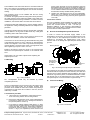
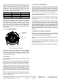
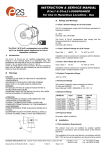
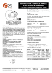
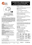
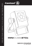
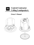
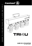
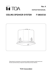
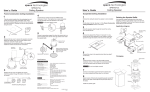
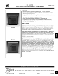
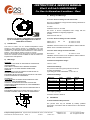
INSTRUCTION & SERVICE MANUAL
D1xL1 & D1xL2 LOUDSPEAKER
For Use In Hazardous Locations – Dust
3)
Ratings and Markings
3.1 Class / Division Ratings for US and Canada
The D1x Loudspeakers comply with the following standards for
hazardous locations:
UL 1203
CAN/CSA C22.2 No. 25-1966
The D1xL1 & D1xL2 Loudspeakers also comply with the
following standards for signaling equipment:
UL1480
CSA C22.2 NO. 205-12
The D1xL1 & D1xL2 Loudspeakers are certified
by UL as Audible-signal Appliances for Use in
Hazardous Locations
1)
Introduction
The D1xL1 & D1xL2 are UL certified loudspeakers which
produce a loud warning signal in a hazardous area. The
loudspeaker are approved for use in Dust applications in Class
II Division 1 & 2 as well as Class II Division 1 & 2 and Class III
Division 1 & 2 as well as Class II Zone 20, 21 and 22.
D1xS1 & D1xS2 alarm horns and D1xC1 & D1xC2 Combined
alarm horn & Strobe are also available as well as variants for
Explosive Dust Atmospheres.
2)
Warnings
CAUTION
TO REDUCE THE RISK OF IGNITION OF HAZARDOUS
ATMOSPHERES:
DISCONNECT FROM SUPPLY BEFORE OPENING.
KEEP TIGHTLY CLOSED WHEN IN OPERATION.
WARNING
FIT SEALING FITTING IN CONDUIT RUNS WITHIN 18
INCHES FROM ENCLOSURE.
EQUIPMENT MUST NOT BE INSTALLED WITH THE HORN
FACING UPWARDS OF HORIZONTAL
ATTENTION
POUR REDUIRE LE RISQUE D’INFLAMMATION DES
ATMOSPHÈRES DANGEREUSES:
COUPER L 'ALIMENTATION AVANT OUVERTURE.
CONSERVER FERMÉ PENDANT LE FONCIONNEMENT.
AVERTISSEMENT
CONDUITS DOIVENT ÊTRE SCELLÉS EN MOINS DE 18
POUCES.
ÉQUIPEMENT NE DOIT PAS ÊTRE INSTALLÉ AVEC LE
KLAXON TOURNÉE VERS LE HAUT DE HORIZONTAL.
3.1 Class / Division Ratings for US & Canada
Class II Div 1
Class III Div 1
FG
T6
Ta -40°C to +70°C
Ta -40°C to +70°C
Installation must be carried out in compliance with the National
Electric Code / Canadian Electric Code
3.2 Class / Zone ratings for US and Canada
Zone 20 IIC
T6
Ta -40ºC to +70°C
Installation must be carried out in compliance with the National
Electric Code / Canadian Electric Code.
3.3 Ambient Temperature Range:
-40ºC to +70ºC
3.4 Enclosure Ratings
The product is rated for ingress protection as follows:
IP rating per EN60529:
IP66
Type rating per UL50E / NEMA250: 4 / 4X / 3R / 13
3.5 Electrical Ratings
Model No.
Input
D1xL1-V070-D
D1xL1-R008-D
D1xL1-R016-D
D1xL2-V070-D
D1xL2-R008-D
D1xL2-R016-D
70V Line
8 Ohm
16 Ohm
70V Line
8 Ohm
16 Ohm
Power
(Watts)
15
15
15
25
25
25
Max I/P
Volts
70
10.95
15.49
70
14.14
20
3.6 Frequency Range
All models: 400Hz to 8000 Hz
4)
Installation
4.1 Safe Installation Requirements
The product must only be installed by suitably qualified
personnel in accordance with the latest issues of the relevant
standards.
__________________________________________________________________________________________________________________
European Safety Systems Ltd. Impress House, Mansell Road, Acton, London W3 7QH
[email protected]
Tel: +44 (0)208 743 8880
www.e-2-s.com
Fax: +44 (0)208 740 4200
Document No. D190-00-251-IS-SC Issue: 3
11-06-15
Sheet 1 of 3
The installation of the units must also be in accordance with the
NEC / CEC and any local regulations and should only be carried
out by a competent electrical engineer who has the necessary
training.
power supply terminals on the low impedance units are
duplicated so that units may be connected in parallel. An
end of line monitoring resistor may be fitted to either type
of unit. Additional entries which are not used must always
be fitted with suitably certified blanking elements
The Equipment must not be installed with the horn facing
upwards of horizontal.
To maintain the ingress protection rating and mode of protection,
the cable entries must be fitted with suitably rated cable entry
and/or blanking devices during installation. If conduit is used for
installation, seal conduit within 18 inches from the enclosure.
d. Replace the explosionproof cover of the loudspeaker,
taking care not to damage the explosionproof threads
and checking that the O-ring seal is in place. Tighten the
cover fully.
4.4 Hornless Variants
If entries are fitted with adaptors they must be suitably rated for
the application. Fitting of blanking elements into adaptors is not
permitted.
The D1x Loudspeaker is also available as a variant with
no horn fitted in the factory. The Horn threaded nose
portion has a fitment thread of 1-3/8” – 18 UNF (to
BS1580 or ANSI B1.1). The customer is responsible for
sourcing and correctly fitting a suitable horn that meets
all of the relevant safety requirements.
If a high IP (Ingress Protection) rating is required then a suitable
sealing washer or O-ring must be fitted under any cable gland
or blanking device with metric threads.
5)
Only the explosionproof cover is to be used for access to the
enclosure for installation, service and maintenance.
Connections are to be made into the terminal blocks using solid
or stranded wire, sizes 0.5-4.0mm2 / AWG 20-12. Wire insulation
needs to be stripped 6-7mm. Wires may be fitted securely with
crimped ferrules. Terminal screws need to be tightened down
with a tightening torque of 0.4 Nm / 3.5 Lb-in.
Access to the Explosionproof Enclosure
In order to connect the electrical supply cables to the
loudspeaker it is necessary to remove the explosionproof cover
to gain access to the explosionproof chamber. This can be
achieved by unscrewing the explosionproof cover, taking
extreme care not to damage the explosionproof threads in the
process
Blanking element
External Earth
Assembly
Earthing connections should be made to the Internal Earth
terminal in the explosionproof chamber or the external earth
stud.
Check that the ‘O’ ring seal is in place before replacing the
explosionproof cover.
4.2 Mounting
(Appropriate
cable glands to
be customer
supplied)
Flameproof
cover
Fig. 2 Accessing the Explosionproof Enclosure.
Fig. 1 Fixing locations.
D1x Loudspeakers should only be installed by trained
competent personnel.
The D1x Loudspeakers may be secured to any flat surface using
the three 7mm fixing holes. The enclosure provides IP66
protection and is suitable for indoor and outdoor use providing it
is positioned so that water cannot collect in the horn, and the
cable entry is sealed.
On completion of the cable wiring installation the explosionproof
threads should be inspected to ensure that they are clean and
that they have not been damaged during installation. Also check
that the ‘O’ ring seal is in place, on the thread diameter in contact
with the flat face of the explosionproof cover. When replacing
the explosionproof cover ensure that it is tightened fully.
6)
70V Line In Wiring
Internal Earth
Terminal
E
D
C
B
A
4.3 Installation procedure
a.
Secure the D1x Loudspeaker to a flat surface via the
three 7mm fixing holes in the mounting bracket.
b. Remove the explosionproof cover of the loudspeaker by
unscrewing it, taking care not to damage the threads in
the process (Refer to section 5).
c. Fit an M20x1.5 suitably certified cable gland or ½” NPT
conduit into the corresponding entry in the enclosure and
connect the field wiring to the appropriate loudspeaker
terminals as shown in section 6 / Fig 3 (70V Line In) or
section 7 / Fig 4 (Low Impedance) of this manual. The
Fig. 3 Line in Terminals
_________________________________________________________________________________________________________________
European Safety Systems Ltd. Impress House, Mansell Road, Acton, London W3 7QH
[email protected]
Tel: +44 (0)208 743 8880
www.e-2-s.com
Fax: +44 (0)208 740 4200
Document No. D190-00-251-IS-SC Issue: 3
11-06-15
Sheet 2 of 3
The cable connections are made into the terminal blocks on the
PCB assembly located in the explosionproof enclosure. See
section 5 of this manual for access to the explosionproof
enclosure. The 70V Line loudspeakers are fitted with a five way
terminal block. Terminal A is common and one of the other
terminals B, C, D or E should be selected depending on what
output level is required (see table below).
Terminals
A-B
A-C
A-D
A-E
D1xL2 (25W)
25W
12.5W
6W
2W
D1xL1 (15W)
15W
7.5W
3W
1W
A single wire with a cross sectional area of up to 4.0mm² /
AWG12 can be connected to each terminal way or if an input
and output wire is required two wires up to 2.5mm² wires can be
connected to each terminal way. If more than one wire is fitted
into a terminal a ferrule should be used to secure the wires.
When connecting wires to the terminals great care should be
taken to dress the wire so that when the cover is inserted into
the chamber the wires do not exert excess pressure on the
terminal blocks.
7)
Low Impedance Wiring
9)
End of Line DC Monitoring
On D1xL2 and D1xL1 Loudspeakers, DC line monitoring can be
used if required. Both the 70V Line units and the Low Impedance
units have blocking capacitors fitted. It should be noted that each
loudspeaker has a 1M ohm bleed resistor connected across the
blocking capacitor and this should be taken into account when
selecting the value of the end of line monitoring resistance.
The end of line monitoring resistor can be connected across the
terminals on the end of line unit.
On 70V line units the end of line resistor used must have a
minimum resistance value of 4k7 ohms and a minimum wattage
of 2.5 watts
On low impedance units the end of line resistor used must have
a minimum resistance value of 2k ohms and a minimum wattage
of 0.5 watts or a minimum resistance value of 500 ohms and a
minimum wattage of 2 watts. On the low impedance units care
must be taken with the polarity of the monitoring voltage. If an
end of line resistor is fitted to a unit the links on the printed circuit
boards of all loudspeakers in the line must be cut for the dc
blocking capacitors to be in circuit in order to dc monitor the line
(see Fig 4).
10) Maintenance, Repair and Overhaul
Internal Earth
Terminal
DC Line
Monitoring Link
Maintenance, repair and overhaul of the equipment should only
be carried out by suitably qualified personnel in accordance with
the current relevant standards and regulations.
Units must not be opened while an explosive atmosphere is
present.
If opening the unit during maintenance operations a clean
environment must be maintained and any dust layer removed
prior to opening the unit.
The threaded flamepath joints are not intended to be repaired.
-
- + +
Fig. 4 Low Impedance Terminals
D1xL2 and D1xL1 8 ohm and 16 ohm low impedance
loudspeakers have dual input terminals on the PCB assembly
for input and output wiring. A cable of up to 4.0mm² can be
connected to each terminal. If DC line monitoring is used cut the
link on the board (see Fig. 4).
8)
Earthing
The unit has both a primary internal and secondary external
earth fixing point.
Internal earth connections should be made to the internal Earth
terminal (see Fig. 3 and 4. It should be fitted to the internal earth
point using a ring crimp terminal to secure the earth conductor.
In addition, external earth connections can be made to the M5
earth stud (see Fig. 2), using a ring crimp terminal to secure the
earth conductor to the earth stud. The external earth crimp ring
should be located between the two M5 plain washers provided
and securely locked down with the M5 spring washer and M5
nut.
The earth conductor should be at least equal in size and rating
to the incoming power conductors but at least a minimum of
0.82mm2 / 18AWG in size.
_________________________________________________________________________________________________________________
European Safety Systems Ltd. Impress House, Mansell Road, Acton, London W3 7QH
[email protected]
Tel: +44 (0)208 743 8880
www.e-2-s.com
Fax: +44 (0)208 740 4200
Document No. D190-00-251-IS-SC Issue: 3
11-06-15
Sheet 3 of 3