1
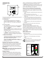
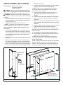
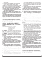
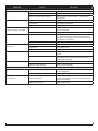
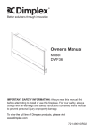
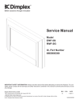
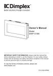
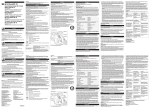
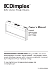
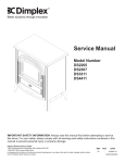
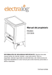
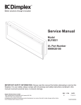
Service Manual
Model
DWF36-PG
UL Part Number
69077001A0
IMPORTANT SAFETY INFORMATION: Always read this manual first before attempting to service this fireplace. For your
safety, always comply with all warnings and safety instructions contained in this manual to prevent personal injury or property damage.
Dimplex North America Limited
1367 Industrial Road Cambridge ON Canada N1R 7G8
1-888-346-7539 www.dimplex.com
In keeping with our policy of continuous product development, we reserve the right to make changes without notice.
© 2011 Dimplex North America Limited
REV
PCN
DATE
00
-
28-NOV-11
7400560000R00
TABLE OF CONTENTS
OPERATION. . . . . . . . . . . . . . . . . . . . . . . . . . . . . . . . . . . . . . . . . . . . . . . . . . . . . . . . . 3
MAINTENANCE . . . . . . . . . . . . . . . . . . . . . . . . . . . . . . . . . . . . . . . . . . . . . . . . . . . . . . 4
EXPLODED PARTS DIAGRAM. . . . . . . . . . . . . . . . . . . . . . . . . . . . . . . . . . . . . . . . . . 5
REPLACEMENT PARTS LIST. . . . . . . . . . . . . . . . . . . . . . . . . . . . . . . . . . . . . . . . . . . 5
WIRING DIAGRAM. . . . . . . . . . . . . . . . . . . . . . . . . . . . . . . . . . . . . . . . . . . . . . . . . . . . 6
HEATER ASSEMBLY REPLACEMENT. . . . . . . . . . . . . . . . . . . . . . . . . . . . . . . . . . . . 7
FLICKER MOTOR REPLACEMENT . . . . . . . . . . . . . . . . . . . . . . . . . . . . . . . . . . . . . . 8
LED LIGHT HARNESS REPLACEMENT. . . . . . . . . . . . . . . . . . . . . . . . . . . . . . . . . . . 9
ON/OFF SWITCH REPLACEMENT. . . . . . . . . . . . . . . . . . . . . . . . . . . . . . . . . . . . . . 10
REMOTE SWITCHBOARD REPLACEMENT . . . . . . . . . . . . . . . . . . . . . . . . . . . . . . . 11
CIRCUIT BOARD REPLACEMENT . . . . . . . . . . . . . . . . . . . . . . . . . . . . . . . . . . . . . 12
Remote Control Receiver or LED Driver Board . . . . . . . . . . . . . . . . . . . . . . . . . . . . . . . . . . . . . . . . . . . . . . 12
TROUBLESHOOTING GUIDE. . . . . . . . . . . . . . . . . . . . . . . . . . . . . . . . . . . . . . . . . . 13
Always use a qualified technician or service agency to repair this fireplace.
! NOTE: Procedures and techniques that are considered important enough to emphasize.
CAUTION: Procedures and techniques which, if not carefully followed, will result in damage to the equipment.
WARNING: Procedures and techniques which, if not carefully followed, will expose the user to the risk of fire, serious
injury, or death.
2www.dimplex.com
OPERATION
Figure 1
A
C
B
The manual controls for the electric fireplace are located on
the right end of the unit.
A. On/Off Switch
The On/Off Switch supplies power to all fireplace
functions. When the switch is in the “ I ” position, the
unit is on. When in the “ O ” position, the fireplace is
off.
B. 3-Position Switch
The 3-Position Switch changes the mode the fireplace
operates in and has three (3) positions: “ MANUAL ”; “
OFF ”; and “ REMOTE ”.
When in “ REMOTE ” mode, the fireplace’s three levels
of operation are controlled by the ON and OFF buttons
of the remote control.
In “ OFF ” mode, power to all functions is cut off.
In “ MANUAL ” mode, the fireplace’s three levels of
operation are controlled by the Manual Control Buttons.
C. Manual Control Buttons
The Manual Control Buttons operate the fireplace levels
sequentially (beginning with): flames only; to flames
and low heat; to flames and high heat.
The level is increased every time the “ I ” button is
pressed. The fireplace can be turned off at any point by
pressing the “ O ” button.
Resetting The Temperature Cutoff Switch
Should the heater overheat, an automatic switch will turn
the heater off and it will not come back on without being
reset. The temperature cutoff switch can be reset by
unplugging the unit, waiting five (5) minutes and plugging
the unit back in.
CAUTION: If you need to continuously reset the heater,
unplug the unit and call Dimplex customer service at
1-888-DIMPLEX (1-888-346-7539).
Remote Control
The fireplace is supplied with a radio frequency remote
control. This remote control has a range of approximately
50 feet (15.25 m). It does not have to be pointed at the
fireplace and can pass through most obstacles (including
walls). It is supplied with one of hundreds of independent
frequencies to prevent interference with other units.
! NOTE: Before attempting any operation with the remote
control, pull the plastic insulator strip out from between the
remote casing and battery cover (Figure 2).
Remote Control Initialization/ Reprogramming
If the remote control or remote control receiver has been
replaced, follow these steps to initialize the remote control
and receiver:
1. Ensure that power is supplied through the main service
panel.
2. Turn On/Off Switch to On (Figure 1A).
3. Move the 3-Position Switch to the “ REMOTE ” position
(Figure 1B).
4. Press and hold the Manual Control Button marked “I”
for five (5) seconds. After five (5) seconds, there is a
10 second window to press any button on the remote
control.
5. Press any button on the remote control within that 10
seconds.
This will synchronize the remote control and receiver.
Remote Control Usage
The remote control operates the fireplace levels
sequentially (beginning with): flames only; to flames and
low heat; to flames and high heat. The level is increased
every time the ON button is pressed on the remote control
and the fireplace can be turned off at any point by pressing
the OFF button.
Battery Replacement
To replace the battery:
1. Slide battery cover open on the remote control (Figure
2).
2. Install one (1) 12-Volt (A23) battery in the battery
holder.
3. Close the battery cover.
Battery must be recycled or disposed of properly.
Check with your Local Authority or Retailer for
recycling advice in your area.
Figure 2
On
Button
Off Button
Plastic
Strip
Battery
Cover
3
MAINTENANCE
WARNING: Disconnect power before attempting any
maintenance or cleaning to reduce the risk of fire, electric
shock or damage to persons.
Mirror Cleaning
The Partially Reflective Glass is cleaned in the factory during the assembly operation. During shipment, installation,
handling, etc., the Partially Reflective Glass may collect
dust particles. These can be removed by dusting lightly
with a clean dry cloth.
To remove fingerprints or other marks, the Partially Reflective Glass can be cleaned with a damp cloth. The Partially
Reflective Glass should be completely dried with a lint free
cloth to prevent water spots. To prevent scratching, do not
use abrasive cleaners.
Fireplace Surface Cleaning
Use only a damp cloth to clean painted surfaces of the
fireplace. Do not use abrasive cleaners.
Servicing
Except for installation and cleaning as described in this
manual, an authorized service representative should perform any other servicing.
4www.dimplex.com
EXPLODED PARTS DIAGRAM
8
3
10
6
4
7
9
1
2
5
REPLACEMENT PARTS LIST
1. Heater Assembly. . . . . . . . . . . . . . . . . . . 2203540100RP
2. Flicker Motor. . . . . . . . . . . . . . . . . . . . . . 2000210300RP
(Order Stand-offs with Flicker Motor. . . 8500410259RP)
3. Flicker Assembly . . . . . . . . . . . . . . . . . . 5902180100RP
4. On/Off Switch . . . . . . . . . . . . . . . . . . . . . 2800070700RP
5. Power Cord . . . . . . . . . . . . . . . . . . . . . . 4100190100RP
6. Remote Control Receiver. . . . . . . . . . . . 3000820100RP
7. Remote Switchboard. . . . . . . . . . . . . . . . 3000820300RP
8. Remote Control. . . . . . . . . . . . . . . . . . . . 3000370900RP
9. LED Light Strip. . . . . . . . . . . . . . . . . . . . 3000830101RP
10. LED Driver Board. . . . . . . . . . . . . . . . . . 3000810100RP
11. Capacitor. . . . . . . . . . . . . . . . . . . . . . . . . 2300030100RP
12. Wall Bracket Mounting Kit. . . . . . . . . . . . 1024380100RP
13. Glass Media . . . . . . . . . . . . . . . . . . . . . . 1400070100RP
5
WIRING DIAGRAM
6www.dimplex.com
HEATER ASSEMBLY REPLACEMENT
Tools Required: Philips head screwdriver
Flat head screwdriver
Needle-nose pliers
WARNING: If the fireplace was operating prior to servicing, allow at least 10 minutes for light bulbs and heating
elements to cool off to avoid accidental burning of skin.
WARNING: Disconnect power before attempting any
maintenance to reduce the risk of electric shock or damage
to persons.
1. Remove the fireplace from the wall by carefully lifting it
upward, releasing it from the flanges of the wall-mounting bracket. (Figure 3).
2. Carefully lay the fireplace down on its front.
! NOTE: If necessary, lay a protective barrier between
the front glass and your work surface, (i.e. cloth, cardboard, thick plastic) to avoid scratching the glass or your
work surface.
3. Remove the left and right side exterior cover panels
from the body of the firebox by removing the screw on
the top flange and two (2) screws on the bottom flange
on each panel, 6 screws in total. (See Figure 4 for all
screw locations.)
4. Remove the six (6) screws from the bottom edge of the
back panel.
5. Remove the twelve (12) screws which secure the bottom panel to the fireplace: two (2) on the left and two
(2) on the right (side flange); three (3) on the left and
three (3) on the right (corner point of the bottom panel);
two (2) in the center of the bottom panel (edge closest
Figure 3
toward the front face).
6. Carefully pull the bottom panel away from the fireplace
and rest it just in front of the bottom opening.
! NOTE: Take care not to damage the wires from the
power cord, which are still attached to both the bottom
panel and the interior switches.
7. Locate the heater assembly and remove the two (2)
heater assembly brackets from the back panel.
(Figure 5)
8. Carefully remove the heater assembly out through the
bottom opening of the fireplace leaving the wires still
connected.
9. Remove the two (2) mounting brackets from the original
heater assembly, and re-attach them to the new heater
assembly.
10. Carefully transfer the wire connections from the original
heater assembly onto the new heater assembly.
! NOTE: Use a flat head screwdriver to gently pry between the end of the connector and the heater assembly to
release the wires.
11. Re-attach the mounting brackets to the back panel.
12. Re-assemble the remainder of the fireplace in reverse
order from the instructions above.
! NOTE: Be sure that the side flanges on the bottom
panel are positioned on the interior of the side and back
panels of the fireplace.
The air deflector panel located on the interior of the bottom
panel will need to carefully fit over the heater assembly
elements. This may take some careful maneuvering, sliding one side of the bottom panel in place first before the
Figure 4
Wall Bracket
Supports
Wall Bracket
Screw Locations
Exterior Cover Plate Screws
Back Panel Screws
Front Glass Assembly Screws
Bottom Panel Screws
7
Figure 5
Heater Mounting Brackets
second side.
The fit is tight and a flat instrument such as a flat head
screwdriver may be helpful to guide the last of the 2 sides
when pushing the bottom panel in place. Use care to not
scratch the visible surface of the bottom.
FLICKER MOTOR REPLACEMENT
Tools Required: Philips head screwdriver
Flat head screwdriver
Needle-nose pliers
Wire Cutters
WARNING: If the fireplace was operating prior to servicing, allow at least 10 minutes for light bulbs and heating
elements to cool off to avoid accidental burning of skin.
WARNING: Disconnect power before attempting any
maintenance to reduce the risk of electric shock or damage
to persons.
1. Remove the fireplace from the wall by carefully lifting it
upward, releasing it from the flanges of the wall-mounting bracket. (Figure 3).
2. Carefully lay the fireplace down on its front.
! NOTE: If necessary, lay a protective barrier between
the front glass and your work surface, (i.e. cloth, cardboard,
thick plastic) to avoid scratching the glass or your work
surface.
3. Remove the left and right side exterior cover panels
from the body of the firebox by removing the screw on
the top flange and two (2) screws on the bottom flange
on each panel, six (6) screws in total. (See Figure 4 for
all screw locations.)
4. Remove the six (6) screws from the bottom edge of the
back panel.
5. Turn the fireplace over and lay it with the front glass
assembly facing up.
6. Remove glass assembly beginning with the four (4)
screws on the top panel. They are located along the
edge of the flat top-panel of the fireplace, where it
meets the angled panel of the glass assembly.
7. Remove the screws from the secondary side panels two (2) on the left and two (2) on the right, which attach
the glass assembly to the body of the fireplace.
WARNING: Do not remove the screws located in the
notched/cutout areas on these side panels where they
meet the angled panels on the left and right sides. These
hold the interior Partially Reflective Glass brackets in place
and may cause the Partially Reflective Glass to fall and
break.
8. Lift the glass assembly off the body of the fireplace and
set it aside in a safe location.
9. Remove the twelve (12) screws which secure the bottom panel to the fireplace: two (2) on the left and two
(2) on the right (side flange); three (3) on the left and
three (3) on the right (corner peak of the bottom panel);
two (2) in the center of the bottom panel (edge toward
the front face).
10. Carefully pull the bottom panel away from the fireplace
and rest it just in front of the bottom opening.
! NOTE: Take care not to damage the wires from the
power cord, which are still attached to both the bottom
panel and the interior switches.
! IMPORTANT:
• If the flicker motor wires are connected into the bottom
terminals on the terminal block, continue with Steps 11 – 16.
• If the flicker motor wire connections are on the top side
of the terminal block, proceed to step 17.
11. With the bottom panel removed, locate the On/Off
Switch and remove the red remote control receiver wire
and the black power cord wire from the switch terminals, noting their original location. .
12. Disconnect the white power cord wire from the remote
control receiver, labeled T4 AC1(L).
13. Gently pull the white connector to disconnect it from the
Remote Switchboard.
14. Leaving the rest of the wire connections in place, remove the remote control receiver by either:
• If you do not have replacement mounting tabs - Use
needle nose pliers to squeeze the flanged tip of each
peg to release the board. Once repair is complete, respread the flanges and re-mount the board.
• If you have replacement pegs - cut the mounting pegs
from each corner. It is best to cut them flush to the
back panel from underneath the board using wire cutters.
15. Carefully grasp the remote control receiver and move
it slightly forward, outside of the lower cavity to provide
better access to the terminal block. Take care that the
Figure 6
Flicker Rod
Mounting Bracket
8www.dimplex.com
antenna from the board stays secured to the upperback panel and the remaining wire connections on the
board stay in-tact.
16. If mounting tabs have been cut, push the remainder of
the tabs out through the back panel
17. Inside the lower cavity, locate the terminal block on the
right hand side and the wires leading from the flicker
motor in the upper housing.
18. Remove the three (3) flicker motor wires from the
terminal block by using a Philips screw driver to loosen
the screw in each of the associated terminals. Note the
original wire locations and orientation of the capacitor.
19. Remove the three (3) screws, which secure the mounting bracket to the bottom of the upper cavity. (Figure 6)
20. Remove the two (2) screws which secure the flicker
motor to the mounting bracket and remove the motor.
21. Carefully pull and twist the rubber gasket and reflector
rod off of the motor shaft, taking care not to bend the
rod. If the rod gets bent, it may cause a rubbing noise
once the fireplace is re-assembled.
22. Remove the original flicker motor and remove the
rubber barrier that mounts between the motor and the
bracket.
23. Fit the rubber barrier onto the new flicker motor and
mount the flicker motor onto the mounting bracket.
24. Feed the flicker motor wires through the opening on the
bottom panel.
25. Re-connect the rubber gasket and flicker rod to the
flicker motor and re-attach the mounting bracket to the
bottom of the upper cavity.
! NOTE: Ensure that the flicker rod is not bent and the
bushing in the center of the flicker rod is completely set in
the support bracket. The bushing must be properly aligned
for it to go all the way down into the bracket.
26. Reconnect the flicker motor wires and capacitor into
the appropriate terminals in the terminal block, according to their original configuration.
! NOTE: It is helpful to use needle nose pliers to feed
the wires and hold them in position with one hand while
you secure the terminal screw into position with the other.
Once the screw is tightened, give a gentle tug on the wires
to ensure they are secure.
27. Install the new mounting tabs, if applicable. Line up
the remote control receiver and gently push it down to
secure it onto the mounting pegs.
28. Reconnect the wires for the On/Off switch, Remote
Switchboard, power cord and Remote Control Receiver
into their original positions.
29. Re-assemble the remainder of the fireplace in reverse
order from the instructions above.
! NOTE: Be sure that the flanges on the bottom panel
are positioned on the interior of the side and back panels of
the fireplace.
The air deflector panel located on the interior of the bottom
panel will need to be carefully fit over the heater assembly
elements. This may take some careful maneuvering, sliding one side of the bottom panel in place first before the
second side.
The fit is tight and a flat instrument such as a flat head
screwdriver may be helpful to guide the second side when
pushing the bottom panel in place. Use care to not scratch
the visible surface of the bottom.
LED LIGHT HARNESS REPLACEMENT
Tools Required: Philips head screwdriver
Flat head screwdriver
Needle-nose pliers
WARNING: If the fireplace was operating prior to servicing, allow at least 10 minutes for light bulbs and heating
elements to cool off to avoid accidental burning of skin.
WARNING: Disconnect power before attempting any
maintenance to reduce the risk of electric shock or damage
to persons.
1. Remove the fireplace from the wall by carefully lifting it
upward, releasing it from the flanges of the wall-mounting bracket. (Figure 3).
2. Carefully lay the fireplace down on its front.
! NOTE: If necessary, lay a protective barrier between
the front glass and your work surface, (i.e. cloth, cardboard,
thick plastic) to avoid scratching the glass or your work
surface.
3. Remove the left and right side exterior cover panels
from the body of the firebox by removing the screw on
the top flange and two (2) screws on the bottom flange
on each panel, six (6) screws in total. (See Figure 4 for
all screw locations.)
4. Remove the six (6) screws from the bottom edge of the
back panel.
5. Turn the fireplace over and lay it with the front glass
assembly facing up.
6. Remove glass assembly beginning with the four (4)
screws on the top panel. They are located along the
edge of the flat top-panel of the fireplace, where it
meets the angled panel of the glass assembly.
7. Remove the screws from the secondary side panels two on the left and two on the right, which attach the
glass assembly to the body of the fireplace.
WARNING: Do not remove the screws located in the
notched/cutout areas on these side panels where they
meet the angled panels on the left and right sides. These
hold the interior Partially Reflective Glass brackets in place
and may cause the Partially Reflective Glass to fall and
break.
8. Lift the glass assembly off the body of the fireplace and
set it aside in a safe location.
9. Carefully pull and twist the rubber gasket and reflector
rod off of the motor shaft, taking care not to bend the
rod. If the rod gets bent, it may cause a rubbing noise
9
once the fireplace is re-assembled.
10. Remove the two (2) screws which secure the center
flicker rod support bracket in place. Set this center
support bracket aside.
11. Remove the twelve (12) screws which secure the bottom panel to the fireplace: two (2) on the left and two
(2) on the right (side flange); three (3) on the left and
three (3) on the right (corner peak of the bottom panel);
two (2) in the center of the bottom panel (edge toward
the front face).
12. Carefully pull the bottom panel away from the fireplace
and rest it just in front of the bottom opening.
! NOTE: Take care not to damage the wires from the
power cord, which are still attached to the bottom panel and
the interior switches.
13. Inside the lower electrical housing compartment, locate
the two (2) orange wire nuts. Untwist the wire-nut
connectors to separate the wires from the LED driver
board and the LED light strip. Note their original locations: yellow wire and the solid black wire connected
together; red wire and black with the orange striped
wire connected together.
! NOTE: The wires from the LED light strip come from
the upper compartment through the opening into the lower
compartment.
14. In the upper compartment, remove the 2 screws which
secure the LED light strip to the light bracket. Screws
are located between the 1st and 2nd bulb and the 4th
and 5th bulb.
15. With wire cutters, cut the wire ties which secure the
LED light strip to the light bracket, (left and right bottom
corner of the bracket).
16. Pull the LED light strip out of the light bracket and pull
the remainder of the wires out of the protective sheathing leading down into the lower compartment.
! NOTE: Leave the protective sheathing in place as
Figure 7
much as possible to reuse it with the replacement light harness.
17. Lay the new LED light strip back into the light bracket
and secure with the original 2 screws.
18. Feed the wires back through the protective sheathing
and guide them back into their original position around
the lower corners of the light bracket, then down into
the lower electrical compartment.
19. In the lower electrical compartment, reconnect the LED
light strip to the wires on the LED driver board using
the 2 orange wire-nut connectors. Be sure to follow the
original configuration: yellow wire and the solid black
wire connected together; red wire and black wire, with
the orange stripe, connected together
20. Re-connect the rubber gasket and flicker rod to the
flicker motor in the upper housing.
! NOTE: Ensure that the flicker rod is not bent and the
bushing in the center of the flicker rod is completely set in
the support bracket. The bushing must be properly aligned
for it to go all the way down into the bracket.
21. Re-assemble the remainder of the fireplace in reverse
order from the instructions above.
! NOTE: Be sure that the flanges on the bottom panel
are positioned on the interior of the side and back panels of
the fireplace.
The air deflector panel located on the interior of the bottom
panel will need to be carefully fit over the heater assembly
elements. This may take some careful maneuvering, sliding one side of the bottom panel in place first before the
second side.
The fit is tight and a flat instrument such as a flat head
screwdriver may be helpful to guide the second side when
pushing the bottom panel in place. Use care to not scratch
the visible surface of the bottom.
ON/OFF SWITCH REPLACEMENT
Tools Required: Philips head screwdriver
Flat head screwdriver
Needle-nose pliers
WARNING: If the fireplace was operating prior to servicing, allow at least 10 minutes for light bulbs and heating
elements to cool off to avoid accidental burning of skin.
Center Support Bracket
LED Light Strip
LED Light Bracket
WARNING: Disconnect power before attempting any
maintenance to reduce the risk of electric shock or damage
to persons.
1. Remove the fireplace from the wall by carefully lifting it
upward, releasing it from the flanges of the wall-mounting bracket. (Figure 3).
2. Carefully lay the fireplace down on its front.
! NOTE: If necessary, lay a protective barrier between
the front glass and your work surface, (i.e. cloth, cardboard,
thick plastic) to avoid scratching the glass or your work
surface.
3. Remove the left and right side exterior cover panels
10www.dimplex.com
from the body of the firebox by removing the screw on
the top flange and two (2) screws on the bottom flange
on each panel, six (6) screws in total. (See Figure 4 for
all screw locations.)
4. Remove the six (6) screws from the bottom edge of the
back panel.
5. Turn the fireplace over and lay it with the front glass
assembly facing up.
6. Remove the twelve (12) screws which secure the bottom panel to the fireplace: two (2) on the left and two
(2) on the right (side flange); three (3) on the left and
three (3) on the right (corner peak of the bottom panel);
two (2) in the center of the bottom panel (edge toward
the front face).
7. Carefully pull the bottom panel away from the fireplace
and rest it just in front of the bottom opening.
! NOTE: Take care not to damage the wires from the
power cord, which are still attached to the bottom panel and
the interior switches.
8. With the bottom panel removed, locate the On/Off
switch on the right hand side.
9. With the bottom panel removed, locate the On/Off
switch and remove the red remote control receiver wire
and the black power cord wire from the switch terminals, noting their original location.
! NOTE: Use a flat head screwdriver to gently pry
between the end of the connector and the switch to release
the wires.
10. Squeeze the mounting tabs located on the top and bottom of the switch, to release the switch and push it out
through the side panel of the fireplace. Note its original
on/off position in the opening.
! NOTE: It may be helpful to use needle-nose pliers for a
better grip and squeeze the mounting tabs simultaneously,
then push the switch outward. Alternatively, a flat head
screw driver can be used to press the each mounting tab
down individually and pushing the switch out, alternating
sides until the switch is released from its position.
11. Replace the original On/Off switch with the new switch,
ensuring the correct orientation.
12. Reconnect the wires according to their original configuration.
13. Re-assemble the remainder of the fireplace in reverse
order from the instructions above.
! NOTE: Be sure that the flanges on the bottom panel
are positioned on the interior of the side and back panels of
the fireplace.
The air deflector panel located on the interior of the bottom
panel will need to be carefully fit over the heater assembly
elements. This may take some careful maneuvering, sliding one side of the bottom panel in place first before the
second side.
The fit is tight and a flat instrument such as a flat head
screwdriver may be helpful to guide the second side when
pushing the bottom panel in place. Use care to not scratch
the visible surface of the bottom.
REMOTE SWITCHBOARD
REPLACEMENT
Tools Required: Philips head screwdriver
Flat head screwdriver
Needle-nose pliers
WARNING: If the fireplace was operating prior to servicing, allow at least 10 minutes for light bulbs and heating
elements to cool off to avoid accidental burning of skin.
WARNING: Disconnect power before attempting any
maintenance to reduce the risk of electric shock or damage
to persons.
1. Remove the fireplace from the wall by carefully lifting it
upward, releasing it from the flanges of the wall-mounting bracket. (Figure 3).
2. Carefully lay the fireplace down on its front.
! NOTE: If necessary, lay a protective barrier between
the front glass and your work surface, (i.e. cloth, cardboard,
thick plastic) to avoid scratching the glass or your work
surface.
3. Remove the left and right side exterior cover panels
from the body of the firebox by removing the screw on
the top flange and two (2) screws on the bottom flange
on each panel, six (6) screws in total. (See Figure 4 for
all screw locations.)
4. Remove the six (6) screws from the bottom edge of the
back panel.
5. Turn the fireplace over and lay it with the front glass
assembly facing up.
6. Remove the twelve (12) screws which secure the bottom panel to the fireplace: two (2) on the left and two
(2) on the right (side flange); three (3) on the left and
three (3) on the right (corner peak of the bottom panel);
two (2) in the center of the bottom panel (edge toward
the front face).
7. Carefully pull the bottom panel away from the fireplace
and rest it just in front of the bottom opening.
! NOTE: Take care not to damage the wires from the
power cord, which are still attached to the bottom panel and
the interior switches.
8. With the bottom panel removed, locate the Remote
Switchboard on the right hand side.
9. Disconnect the wire harness, connecting the remote
switchboard to the remote control receiver on the interior back panel.
10. Remove the switchboard, by depressing the flanged
tips on the mounting tabs using needle nose pliers and
gently lifting off.
11. Once the switchboard is removed, use needle nose
pliers to push the original mounting tabs out of the fireplace chassis and replace with the new mounting tabs
supplied with the new board.
12. Gently push the new remote switchboard onto these
11
mounting tabs.
13. Connect the new switchboard to the remote control
receiver using the new wire harness supplied.
! NOTE: The wire harness plugs will insert only one way
onto the remote control receiver and the remote switchboard. Ensure that the plug is oriented so that the shape/
configuration matches before pushing them in place.
14. Re-assemble the remainder of the fireplace in reverse
order from the instructions above.
! NOTE: Be sure that the flanges on the bottom panel
are positioned on the interior of the side and back panels of
the fireplace.
The air deflector panel located on the interior of the bottom
panel will need to be carefully fit over the heater assembly
elements. This may take some careful maneuvering, sliding one side of the bottom panel in place first before the
second side.
The fit is tight and a flat instrument such as a flat head
screwdriver may be helpful to guide the second side when
pushing the bottom panel in place. Use care to not scratch
the visible surface of the bottom.
CIRCUIT BOARD REPLACEMENT
REMOTE CONTROL RECEIVER or LED DRIVER
BOARD
Tools Required: Philips head screwdriver
Flat head screwdriver
Needle-nose pliers
Wire Cutters
WARNING: If the fireplace was operating prior to servicing, allow at least 10 minutes for light bulbs and heating
elements to cool off to avoid accidental burning of skin.
WARNING: Disconnect power before attempting any
maintenance to reduce the risk of electric shock or damage
to persons.
1. Remove the fireplace from the wall by carefully lifting it
upward, releasing it from the flanges of the wall-mounting bracket. (Figure 3).
2. Carefully lay the fireplace down on its front.
! NOTE: If necessary, lay a protective barrier between
the front glass and your work surface, (i.e. cloth, cardboard,
thick plastic) to avoid scratching the glass or your work
surface.
3. Remove the left and right side exterior cover panels
from the body of the firebox by removing the screw on
the top flange and two (2) screws on the bottom flange
on each panel, six (6) screws in total. (See Figure 4 for
all screw locations.)
4. Remove the six (6) screws from the bottom edge of the
back panel.
5. Turn the fireplace over and lay it with the front glass
assembly facing up.
6. Remove the twelve (12) screws which secure the bottom panel to the fireplace: two (2) on the left and two
(2) on the right (side flange); three (3) on the left and
three (3) on the right (corner peak of the bottom panel);
two (2) in the center of the bottom panel (edge toward
the front face).
7. Carefully pull the bottom panel away from the fireplace
and rest it just in front of the bottom opening.
! NOTE: Take care not to damage the wires from the
power cord, which are still attached to the bottom panel and
the interior switches.
8. With the bottom panel removed, locate the board to be
replaced. There are two (2) circuit boards to the right
of the heater assembly, mounted on the back panel
of the fireplace: the LED Driver Board is the medium
sized board located closest to the heater; and the
Remote Control Receiver is the large board located
closest to the switches on the right.
9. Transfer the wire connectors from the terminals on the
original board to the same location on the replacement
board.
! NOTE: Use a flat head screwdriver to gently pry
between the end of the connector and the switch to release
the wires.
10. Using wire cutters, remove the defective board by cutting the 4 mounting tabs which secure the board to the
back panel. They can be cut either from: above – flush
to the board; or below the board - flush to the back
panel. Once the mounting tabs are cut, pull the board
off of the tabs, and remove the board from its location,
noting its original orientation.
11. Raise the bottom of the fireplace off your work surface
and using needle nose pliers push the remainder of the
original mounting tabs out of the back panel and push
the new mounting tabs (supplied with the new board),
into the same location from behind the panel.
12. Gently push the new board onto these mounting tabs
according to the orientation of the original board.
! NOTE: The wire harness plugs will insert only one way
onto the remote receiver board and the remote switchboard
Ensure that the plug is oriented so that the shape/configuration matches before pushing them in place.
13. Re-assemble the remainder of the fireplace in reverse
order from the instructions above.
! NOTE: Be sure that the flanges on the bottom panel
are positioned on the interior of the side and back panels of
the fireplace.
The air deflector panel located on the interior of the bottom
panel will need to be carefully fit over the heater assembly
elements. This may take some careful maneuvering, sliding one side of the bottom panel in place first before the
second side.
The fit is tight and a flat instrument such as a flat head
screwdriver may be helpful to guide the second side when
pushing the bottom panel in place. Use care to not scratch
the visible surface of the bottom.
12www.dimplex.com
TROUBLESHOOTING GUIDE
PROBLEM
CAUSE
SOLUTION
General
Circuit breaker trips or fuse
blows when unit is turned on
Short in unit wiring.
Trace wiring in unit.
Improper circuit current rating
Additional appliances may exceed the current rating
of the circuit breaker or fuse. Plug unit into another
outlet or install unit on a dedicated 15 amp circuit.
Unit turns on or off by itself
Remote control has a similar frequency
to other remotes in the area.
Replace Remote Control. Initialize to Remote Control
Receiver.
Radio frequency disturbance from outside sources.
Replace Remote Control and Remote Control Receiver where necessary. Initialize Remote Control and
Receiver
Defective Remote Control Receiver
Replace Remote Control Receiver. Initialize to Remote Control.
Lights dim in room while the unit
is on
Unit is drawing close to circuit current
rating
Move the unit to another outlet or install unit on a dedicated 15 amp circuit
Power cord gets warm
Normal Operation
The power cord may get slightly warm to the touch
when the heater is on
Defective power cord
Replace power cord if cord gets hot to the touch.
Improper operation
Refer to Operation Section
No incoming power from the electrical
wall socket
Check Fuse/Breaker Panel
Defective On/Off Switch
Replace On/Off Switch
Defective Remote Switchboard
Defective Remote Switchboard
Defective Remote Control Receiver
Replace Remote Control Receiver. Initialize with Remote Control.
Improper operation
Refer to Operation Section
Remote control not initialized to fireplace
Initialize the remote control
Loose wiring
Check wiring connections
Remote Control not working
Install new battery into the Remote Control. Reinitialize remote control where necessary
Appearance
Fireplace does not turn on in
Manual Mode
Fireplace does not turn on in
Remote Mode
Replace Remote Control Receiver where necessary.
Initialize Remote Control Receiver to Remote Control.
Defective Remote Control Receiver
Replace Remote Control Receiver. Initialize to Remote Control
Loose wiring
Check wiring connections
Defective flicker motor
Replace flicker motor
Flame not bright or flame not
visible
Loose wiring
Check wiring connections
Defective LED light strip
Replace LED light strip
Log set dim, not glowing
Defective LED Log Driver Board
Replace LED Log Driver Board
Flame Shudder
Defective flicker motor
Replace flicker motor
Flame Frozen
13
PROBLEM
CAUSE
SOLUTION
Heater
Heater is not turning Off
Heater is not turning On
Heater is turning off after a
couple of minutes of operation
Heater emits an odor
Heater fan turns on but heater
lacks heat
Heating element is glowing red
Heater fan runs continuously
Improper operation
Refer to Operation Section
Defective Remote Switchboard
Defective Remote Switchboard
Defective Remote Control Receiver
Replace Remote Control Receiver. Initialize to Remote Control.
Improper operation
Refer to Operation Section
Loose wiring
Check wiring connections
Defective heater assembly
Replace heater assembly
Build up of dirt/dust in heater assembly
Ensure that exterior intake louvers and firebox cavity
are free of dirt/dust.
Defective Heater Assembly
Replace Heater Assembly
Normal Operation
Normal operation is when the heater emits an odor
for a brief period after the heater is initially turned on.
The heater is burning off any dust accumulated during
manufacturing or operation.
Defective heater assembly
Replace heater assembly
Improper operation
Refer to Operation Section
Loose wiring
Trace wiring in unit
Defective heater assembly
Replace heater assembly
Normal Operation
Small glowing sections of the element are considered
normal.
Defective heater assembly
If larger glowing sections are causing the heater to trip
the thermal cutout, unplug unit, discontinue use and
replace heater assembly.
Loose wiring
Trace wiring in unit
Defective heater assembly
Replace heater assembly
Dirty heater assembly
Ensure that exterior intake louvers and firebox cavity
are free of dirt/dust.
Defective heater assembly
Replace heater assembly
Flicker rod hitting or rubbing against
internal components
Ensure rod is straight and mounted properly in the
bracket, spinning freely away from other components.
Replace if necessary.
Defective flicker motor
Replace flicker motor
Noise
Excessive noise with the heater
on
Grinding or excessive noise with
the heater off
14www.dimplex.com